

Samsung LN22A451C1DXZA User Manual
1-800-SAMSUNG (7267864)
Samsung Electronics America, Inc.
105 Challenger Road Ridgefield Park, NJ 07660-0511
Samsung Electronics Canada Inc., Customer Service
55 Standish Court Mississauga, Ontario L5R 4B2
Call center hours of operation (Mon-Sun 9AM-12AM EST).
To register this product please visit
www.samsung.com/global/register.
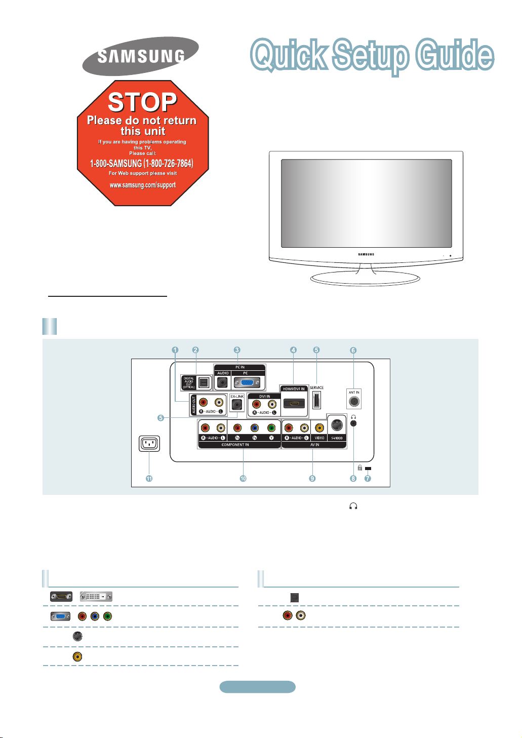
Rear Panel / Side Panel Jacks
LN19A450C1D/LN19A451C1D/
LN22A450C1D/LN22A451C1D
1 AUDIO OUT
2 DIGITAL AUDIO OUT (OPTICAL)
3 PC IN [PC] / [AUDIO]
4 DVI IN[R-AUDIO-L]
/ HDMI/DVI IN
5 SERVICE, EX-LINK
6 ANT IN
7 KENSINGTON LOCK
Video Input Performance Comparison
/
/
HDMI/DVI
PC/COMPONENT
S-VIDEO
VIDEO
Best
Better
Good
Normal
8 HEADPHONE
9 AV IN / S-VIDEO
0 COMPONENT IN
! POWER INPUT
Audio Output Performance Comparison
OPTICAL (Digital)
AUDIO (Analog)
English-1
Best
Normal
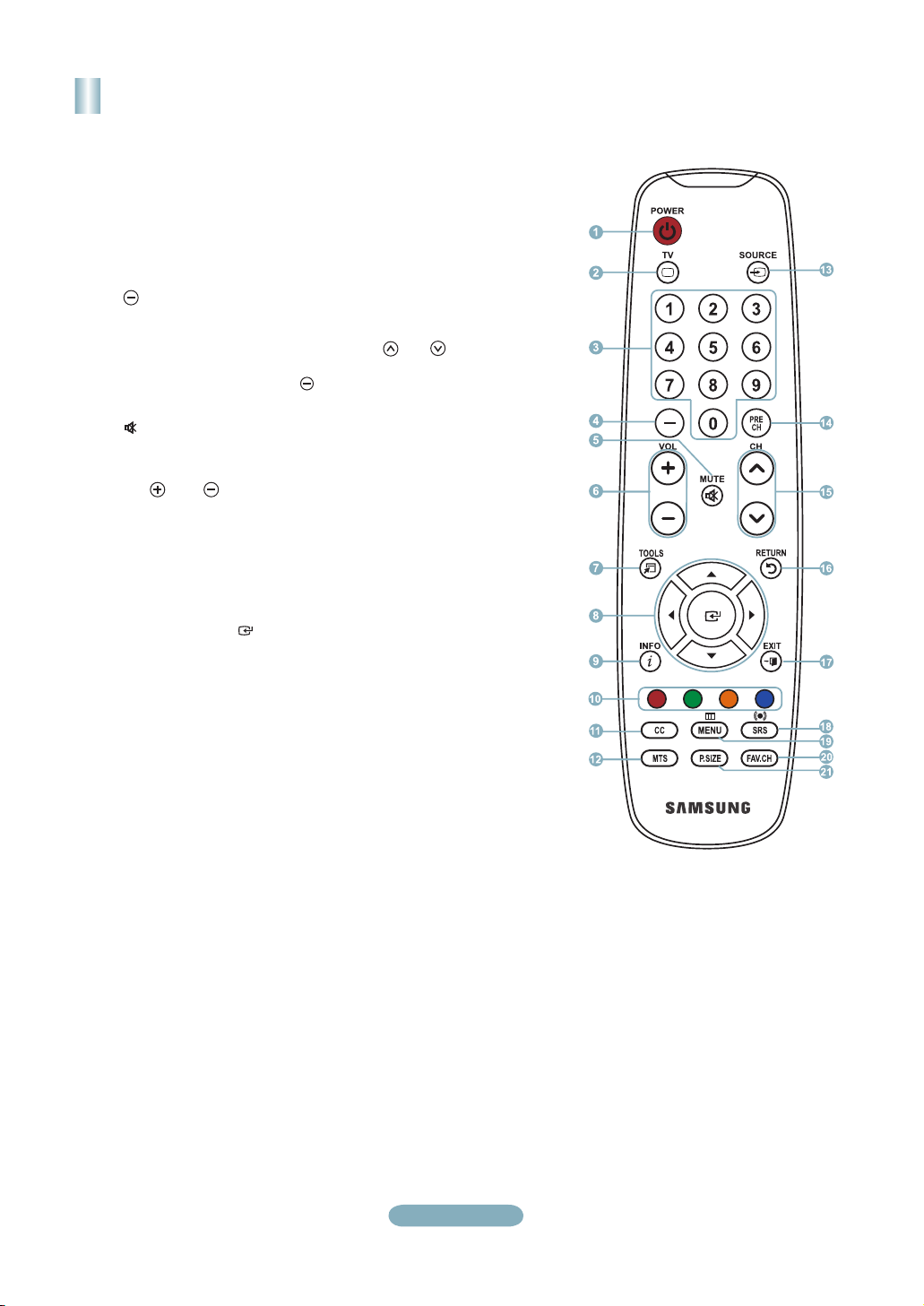
Remote Control
See “Remote Control” in the owner’s instructions for details.
1
POWER
Turns the TV on and off.
2
TV
Selects the TV mode directly.
3
NUMERIC BUTTONS
Press to change the channel.
4
Press to select additional
channels(digital and analog) being
broadcast by the same station.
For example, to select channel
“54-3”, press “54”, then press “ ”
and “3”.
5 (
MUTE)
Press to temporarily cut off the
sound.
6
VOL / VOL
Press to increase or decrease
the volume.
7 TOOLS
Use to quickly select frequently
used functions.
8 UP▲ / DOWN▼ / LEFT◄
RIGHT►
Use to select on-screen menu
items and change menu values.
9 INFO
Press to display information on
the TV screen.
0
COLOR BUTTONS
Use these buttons in the
Channel list, etc.
!
CC
Controls the caption decoder.
/ ENTER
/
@ MTS
Press to choose stereo, mono
or Separate Audio Program
(SAP broadcast).
#
SOURCE
Press to display and select the
available video sources.
$
PRE CH
Tunes to the previous channel.
% CH / CH
Press to change channels.
^
RETURN
Returns to the previous menu.
& EXIT
Press to exit the menu.
*
SRS
Selects SRS TruSurround XT
mode.
(
MENU
Displays the main on-screen
menu.
) FAV.CH
Press to switch to your favorite
channels.
a P.SIZE
Picture size selection.
English-2
Connections
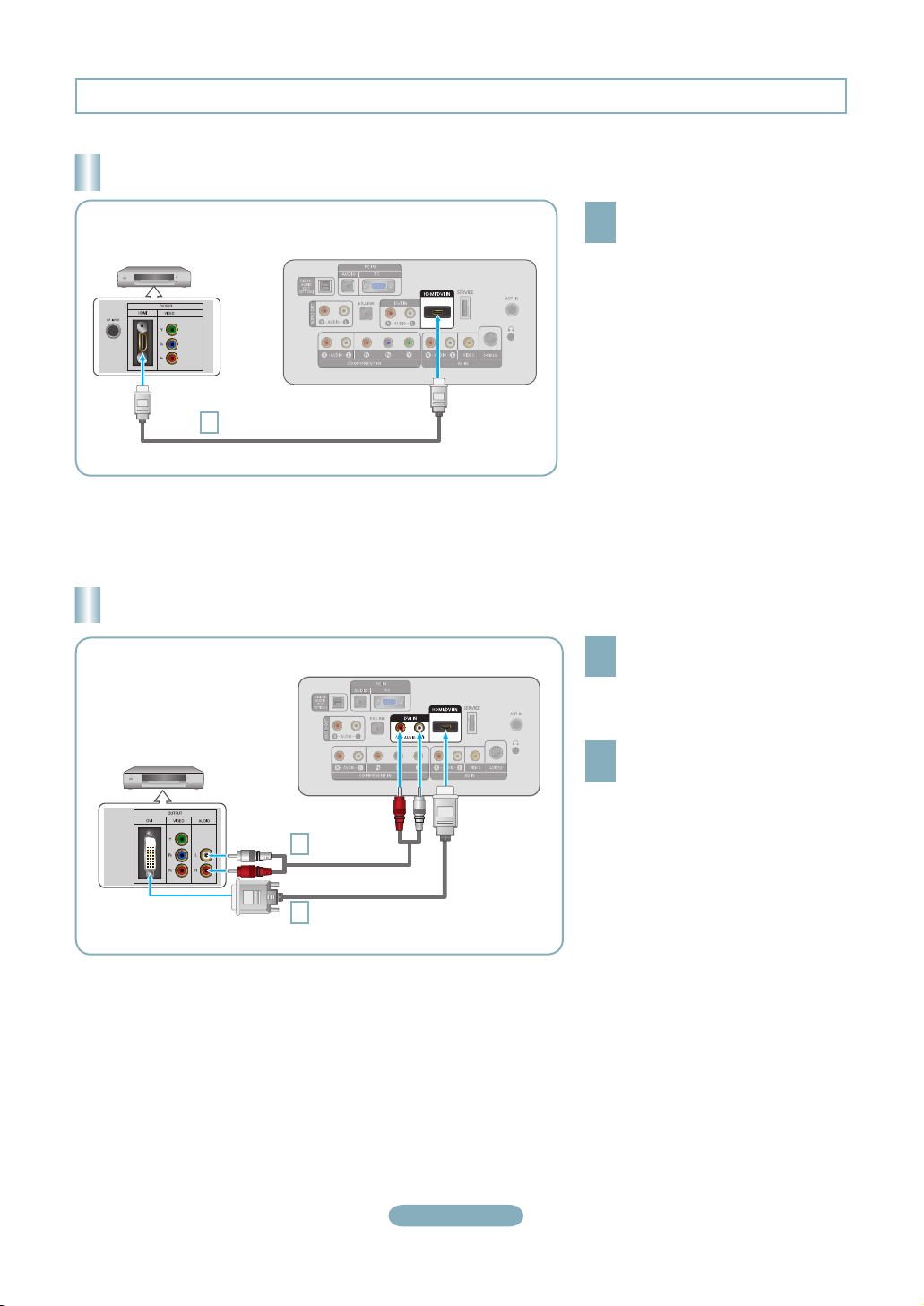
Connecting a DVD Player or Cable Box/Satellite receiver (Set-Top Box) via HDMI
Connect an HDMI Cable between
DVD Player or Cable Box/
Satellite receiver
(Set-Top Box)
HDMI Cable (Not supplied)
1
Each DVD Player or Cable Box/Satellite receiver (Set-Top Box) has a different
➣
back panel configuration.
TV Rear Panel
the HDMI/DVI IN jack on the TV
1
and the HDMI jack on the DVD
Player or Cable Box/Satellite
receiver (Set-Top Box).
What is HDMI?
•
HDMI(High-Definition Multimedia
Interface), is an interface that enables the
transmission of digital audio and video
signals using a single cable.
•
The difference between HDMI and DVI
is that the HDMI device is smaller in
size and has the HDCP (High Bandwidth
Digital Copy Protection) coding feature
installed.
Connecting a DVD Player or Cable Box/Satellite receiver (Set-Top Box) via DVI
Connect a DVI to HDMI Cable or
DVI-HDMI Adapter between the
1
HDMI/DVI IN jack on the TV and the
DVI jack on the DVD Player or Cable
Box/Satellite receiver (Set-Top Box).
Connect Audio Cables between the
DVI IN [R-AUDIO-L] jack on the TV
2
and the DVD Player or Cable Box/
Satellite receiver (Set-Top Box).
DVD Player or Cable Box/
Satellite receiver (Set-Top Box)
TV Rear Panel
Audio Cable
2
(Not supplied)
DVI to HDMI Cable (Not supplied)
1
Each DVD Player or Cable Box/Satellite receiver (Set-Top Box) has a different
➣
back panel configuration.
When connecting a DVD Player or Cable Box/Satellite receiver (Set-Top Box),
➣
match the color of the connection terminal to the cable.
When using an HDMI/DVI cable connection, you must use the HDMI/DVI IN
➣
jack.
English-3
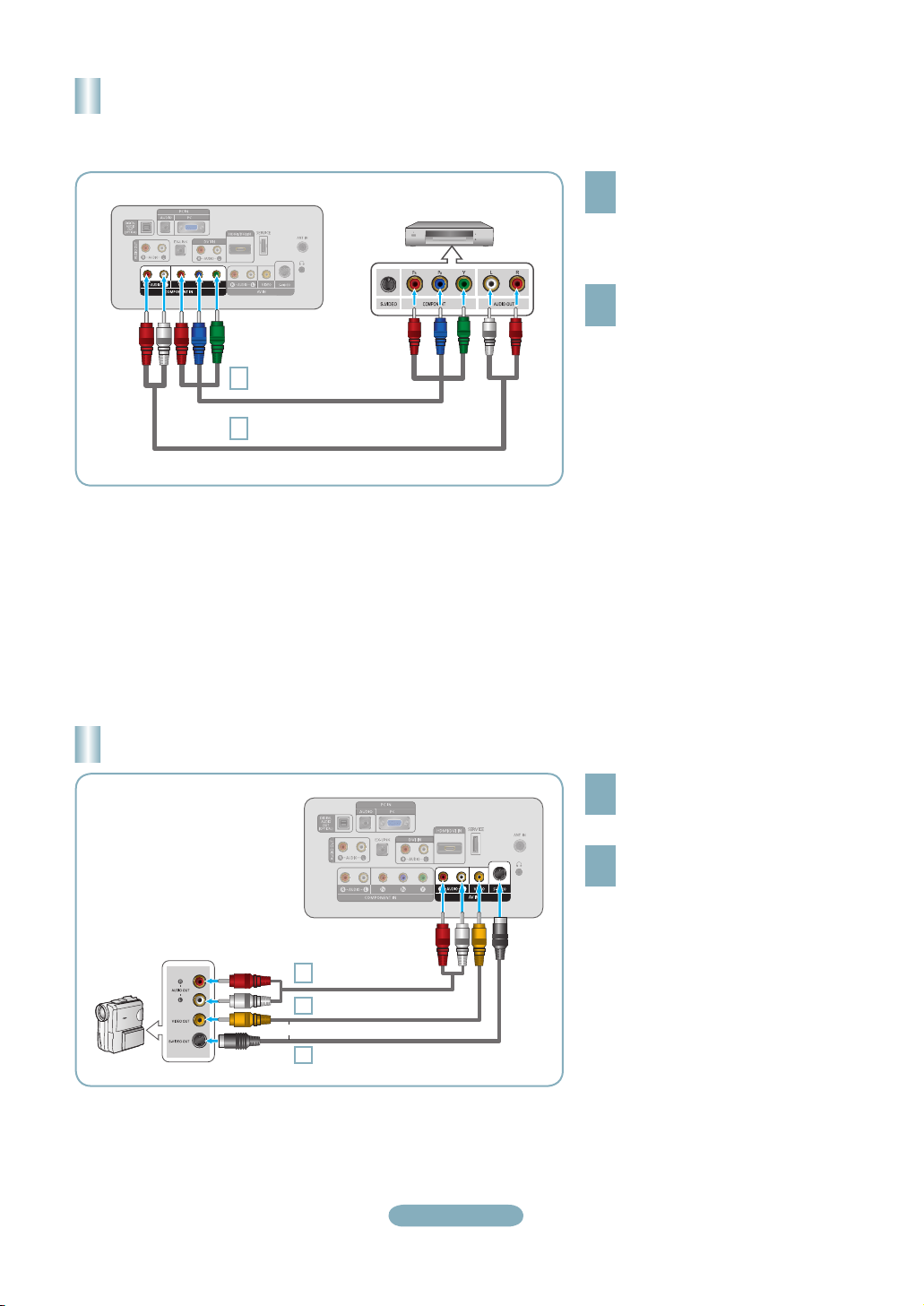
Connecting a DVD Player or Cable Box/Satellite receiver (Set-Top Box)
via Component cables
TV Rear Panel
1
2
DVD Player or Cable Box /
Satellite receiver (Set-Top Box)
Component Cable (Not supplied)
Audio Cable (Not supplied)
Connect a Component Cable between
the COMPONENT IN [Y, PB, PR] jacks
1
on the TV and the COMPONENT [Y,
PB, PR] jacks on the DVD Player or
Cable Box/Satellite receiver (Set-Top
Box).
Connect Audio Cables between the
COMPONENT IN [R-AUDIO-L] jacks
2
on the TV and the AUDIO OUT jacks
on the DVD Player or Cable Box/
Satellite receiver (Set-Top Box).
Component video separates the video
➣
into Y (Luminance (brightness)), Pb
(Blue) and Pr (Red) for enhanced video
quality.
Be sure to match the component video
and audio connections.
For example, if connecting
a Component video cable to
COMPONENT IN, connect the audio
cable to COMPONENT IN also.
Each DVD Player or Cable Box/
➣
Satellite receiver (Set-Top Box) has a
different back panel configuration.
When connecting a DVD Player or
➣
Cable Box/Satellite receiver (Set-Top
Box), match the color of the connection
terminal to the cable.
Connecting a Camcorder
Audio cable (Not supplied)
Camcoder
2
Video Cable (Not supplied)
1
or
S-Video Cable (Not supplied)
1
TV Side Panel
English-4
Connect a Video Cable (or S-Video
Cable) between the AV IN [VIDEO]
1
(or S-VIDEO) jack on the TV and the
VIDEO OUT jack on the camcorder.
Connect Audio Cables between the
AV IN [R-AUDIO-L] jacks on the TV
2
and the AUDIO OUT jacks on the
camcorder.
Each Camcorder has a different back
➣
panel configuration.
When connecting a Camcorder, match
➣
the color of the connection terminal to
the cable.
 Loading...