

Samsung LFH20FWA Users Manual

User Manual
Frame KIT
VG-LFH15FWA VG-LFH20FWA VG-LFH25FWA
The color and the appearance may differ depending on the product, and the
specications are subject to change without prior notice to improve the performance.

Table of contents
Installing Frame KIT
Checking the Components 3
Components 3
Checking the wall when screwing is used 4
Installing Frame KIT 6
Cabinet data flow 12
Cabinet installation procedure 13
Installing a cabinet onto Frame KIT 14
Adjusting the frame spacing and height 16
Adjusting the frame spacing 16
Adjusting the cabinet spacing 16
Adjusting the Frame Z-Bolt height 17
2
Installing Frame KIT
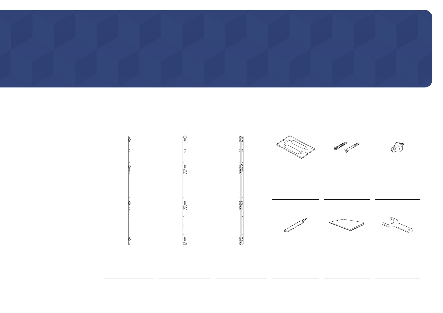
Checking the Components
– Contac t the vendor where you
purchased the product if any
components are missing.
– The pictures may look different from
the actual components.
– One additional ASSY BRACKET
CENTER is provided as spare.
* ASSY SLIDING SCREW is supplied as
a component of the SAMSUNG LED
Signage product.
Components
ASSY BRACKET SIDE
(2 EA)
ASSY BRACKET MIDDLE
(VG-LFH15FWA: 4 EA /
VG-LFH20FWA: 6 EA /
VG-LFH25FWA: 8 EA)
ASSY BRACKET CENTER
(2 EA)
ASSY BRACKET JIG
(2 EA)
Service JIG
ASSY ANCHOR SCREW
(M5, L65)
(VG-LFH15FWA: 32 EA /
VG-LFH20FWA: 50 EA /
VG-LFH25FWA: 72 EA)
Frame KIT Installation
Guide
*ASSY SLIDING SCREW
Wrench
3
Checking the wall when screwing is used
2
3
4
2
3
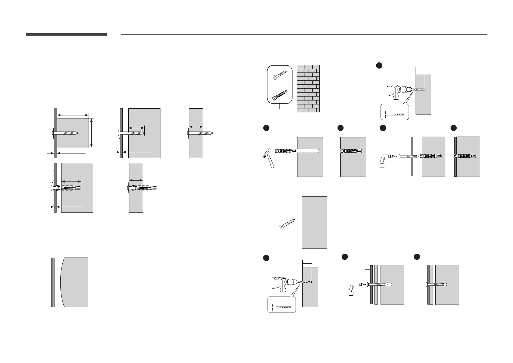
Standard Installation Requirements by Wall Type
[ Check the wall type before installing.
• Can only be mounted on a concrete or interior wall of sufcient thickness. See the diagrams below.
Min. 50 mm
Min. 2.5
mm
MDF, PW (plywo od) (excluding
gypsum board thickn ess)
Artwall
When the re is reinforc ing
wood such as MDF or PW
(plywood)
Min. 10 mm
MDF, PW (plywo od)
Min. 30 mm
Concrete
Min. 10 mm
MDF, PW (plywo od)
Min. 50
mm
Min. 30 mm
MDF, PW (plywo od)
Min. 10 mm
MDF, PW (plywo od)
Min. 2.5
mm
Concre te composite wall
(excluding the gypsum
board thi ckness)
– MDF = Medium Density Fiberboard
PW = Plywood
• First, check the wall conditions (type, thickness, and oor plan).
If the wall surface is not completely at, gaps may form after installation.
1. Walls made of thick enough concrete
Wall
ASS Y A NCHOR SCREW
1
ASS Y B RACKET
2. Walls made of gypsum board with wood studs or MDF
1
65 mm (2.5" )
65 mm (2.5" )
9 mm (3/8")
5
ASS Y B RACKET
LED
Wall
3 mm (1/8")
4
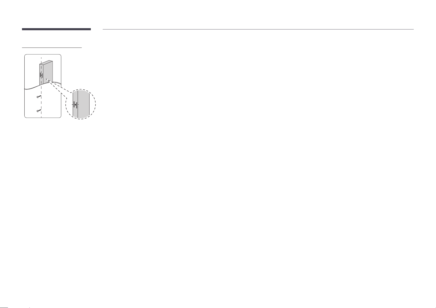
Installation Requirements
15 mm
• Be sure to check the location of wooden studs in the wall before installing
screws.
• Minimum wood stud size: 51 × 102 mm (2 × 4 in)
Make holes (3 mm) rst before installing screws.
• Holes for screws must be made at the center of studs.
• Wood may split when attaching the TV if holes are not made.
• A standard stud distance of 16” is supported. (24” is not supported)
[ Samsung is not responsible for problems that arise when the installation
guide is not followed.
5
Installing Frame KIT
• The installation instructions are given based on the VG-LFH15FWA model. Apply them correctly
according to your model.
• Check the product model as well as the enclosed user manual for each product and check that the
wall allows mounting.
– Be sure the wall is stable. If the wall is weak, reinforce it before installation.
– If the wall is not cement, check with a specialist to determine whether the product may be
installed on it.
– Consult an expert installer if you do not have any background knowledge about the wall you want
to install the product on.
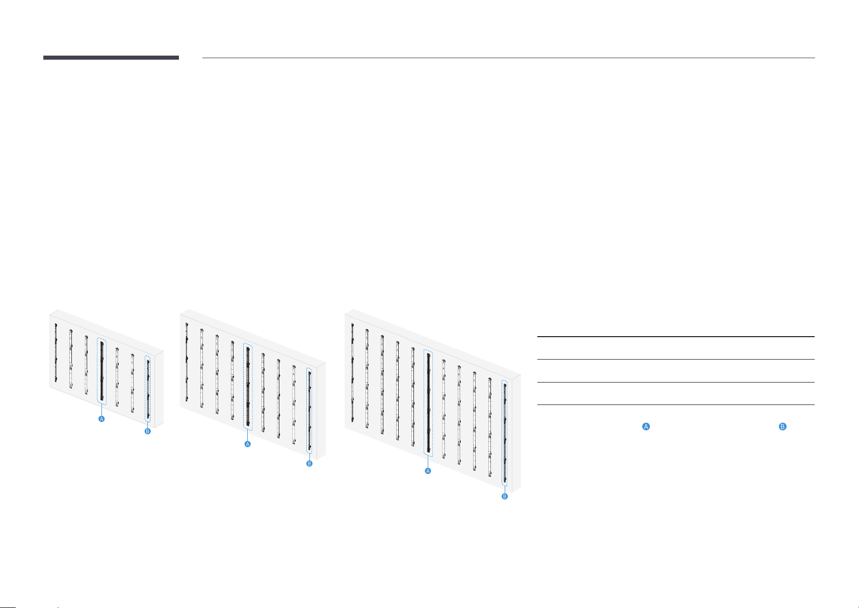
Basic installation examples by model
VG-LFH15FWA: 6 × 3 VG-LFH20FWA: 8 × 4 VG-LFH25FWA: 10 × 5
• To maintain product performance and prevent malfunctions, do not install in the following locations.
– Places where there is a risk of vibration or shock: The product may fall and be damaged.
– Next to a sprinkler sensor: When the sensor detects any heat from the product, the sprinklers may
get activated.
– Near high-pressure cables: The product may get interfered by high-pressure cables. In this case,
the screen may not display correctly.
– Near heaters: The product may become overheated and malfunction.
• Cabinet installation layout and screen size by Frame KIT model
Frame KIT model Cabinet installation
layout
VG-LF H15FWA 6 × 3 2880 × 1620
VG-LF H20FWA 8 × 4 3840 × 2160
VG-LF H25FWA 10 × 5 4800 × 2700
Screen size (mm)
– When installing 2 or more Frame KITs to extend the cabinet installation
layout, install them with
BRACKET SIDE.
When extending the cabinet installation layout, refer to the figures in
Basic installation examples by model.
ASSY BRACKET CENTER instead of ASSY
6
 Loading...