

Page 1

Samsung Electronics
LED Display Installation Manual
IER / IFR Series
LH0**IER*LS
LH0**IER*FS
LH0**IFR*LS
LH0**IFR*FS
Page 2
Samsung Electronics
Revision History
1
Version Date (Y/M/D)
Description
2.0 2020/03/20
New
Release
Page 3

Samsung Electronics
When humidity get into LED package because of high humidity, it is
possible to cause ‘Line defect’ by electrical short in side of LED
Package.
For keeping quality of products during installation, please refer below
cautions.
- If one of below case meet before installation, MUST do dehumidification process.
∙ Case when vacuum packaging is broken before unpacking.
∙ Case when environment condition is exceed Samsung recommended operation condition.
(Please refer Operation condition from User manual)
∙ Case when period between unpacking and turning on the power of products is spent
more than 7days, even though it is under Samsung recommended storage condition.
∙ Case when production date on the label is exceed more than 6 months, even though
vacuum packaging is no problem.
- When Volatile chemicals such as oil paint, solvent are used or operation condition
is exceed around of products installed place, MUST play video more than 2 hours
everyday.
- If it is not meet with upper cases, it is helpful to play video more than 2 hours
everyday for protection for humidity getting into LED Package.
Dehumidification guidance – during installation
Page 4

Samsung Electronics
Electrical short in package is possible to happen during products are
working.
For keeping quality of products during installation, please refer below
cautions.
- If one of below case meet during operation, MUST do dehumidification process.
∙ Case when environment condition is exceed operation condition.
∙ Case when products are not working more than 1 month, even though environment
condition is under operation condition.
- When environment condition is exceed operation condition, products are out of
warranty. Please check environment condition.
- Even products are operating, if the installed place have extra construction such as
interior modification, MUST do dehumidification following installation condition.
- It is possible to happen dew condensation on surface of products, even though
working on operating condition. When happening dew condensation, MUST
operate after cleaning the dew condensation & dehumidification.
Dehumidification guidance – during operation
Page 5
Samsung Electronics
Dew condensation due to overcooling
Even though meet with Samsung recommended operation
condition, dew condensation is possible to happen when
surface of products is colder than environment temperature or
hot & humid air blow to cooled surface of products.
(cf : Principle of happening dew on surface of glass which have ice)
Case when dew condensation is happen on products, it is
possible to be the root of defect. In this case, it is possible to
be out of warranty.
Page 6

Samsung Electronics
When install products, please update latest firmware on online
- You can download latest firmware from SLM site.
∙ URL of SLM Page : https://www.secslm.com
∙ After login Help Download Center에서 Download
∙ Before you download firmware, you MUST check same firmware of model (marked red
letter in below) & upper number of version (marked blue in below).
- You can update firmware through LSM.
∙ Please refer ‘7-1 PC control program’ for the way to update firmware.
5
Guidance of latest firmware
Cabinet : Main - L-xxxMWWAC-nnnn.n xxx = Pan name, nnnn.n = version
FPGA - aabbb_ddddd aa = pixel pitch, bbb = LED package type, ddddd= version
Example : IER P2.5 Cabinet : L-IERMWWAC-1003.1, FPGA : 25252-31046
S-box : TB-KTM2SBMDWWC_100x.x
Page 7
Samsung Electronics
Table of Contents
1. Product Information and Installation Precautions (P.2)
2. Preparation for Cabinet Installation (P.12)
3. Frame Kit (P.16)
4. Frame Installation (P.17)
5. Cabinet + Frame Installation (P.25)
6. S-Box Connection (P.29)
7. Settings / How to Use (P.47)
8. Power and Cable Connection (P.63)
9. Seam Adjustment (P.72)
Appendix. IER-F/IFR-F series Installation Manual (72 page)
6
Page 8
Samsung Electronics
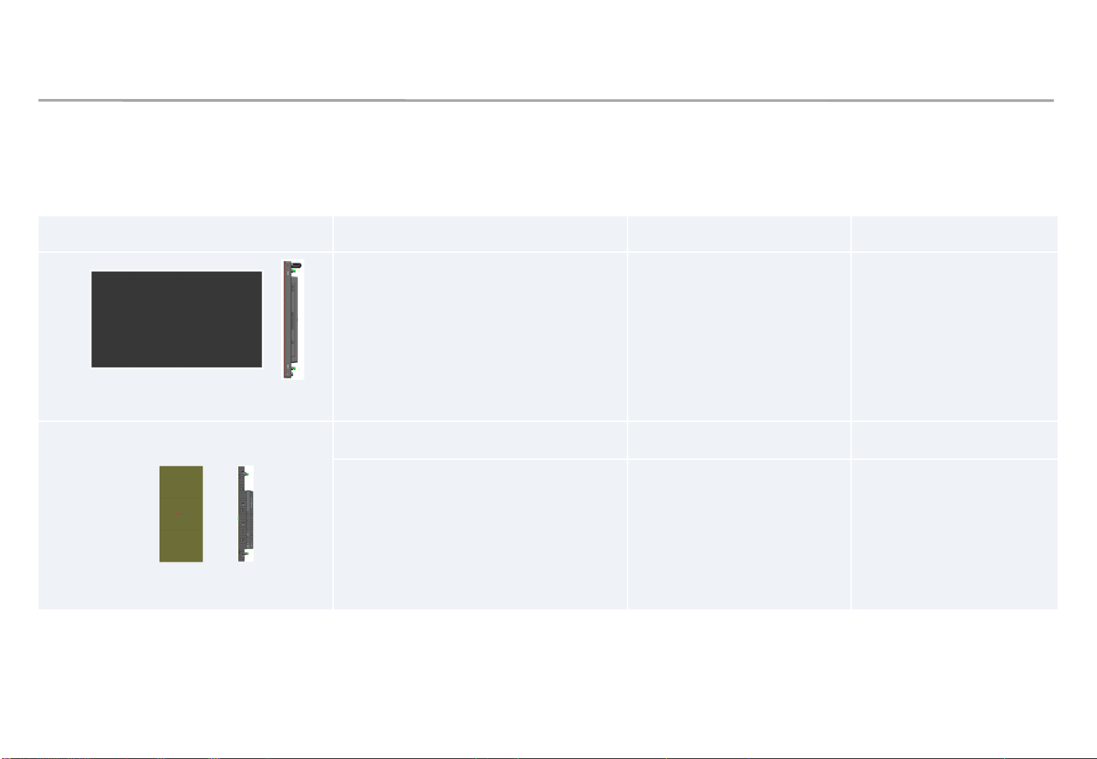
Cabinet Size IER (P2.0, P2.5, P4.0) IFR (P2.5, P4.0)
960x540
(module
4x3)
LH020IER*LS
LH025IER*LS
LH040IER*LS
LH025IFR*LS
LH040IFR*LS
Refer to Manual
(P2~P72)
240x540
(module 1
x3)
IER
-F
(P2.0, P2.5, P4.0)
IFR
-F
(P2.5, P4.0)
LH020IER*FS
LH025IER*FS
LH040IER*FS
LH025IFR*FS
LH040IFR*FS
Refer to
Appendix
(P73~P96)
1. Product Information and Installation Precautions
7
◇ Model Line-up
- IER : Models for Mid-brightness(500~1000nit) with Cupper wire LED
- IFR : Models for High-brightness(1000nit↑) with Gold wire LED
※ IER-F, IFR-F series : Models for Non-Standard Screen (ex. Extend, L-shaped screen). Installation with IER/IFR of same
pitch is recommended.
- This Manual is an Installation Manual for IER/IFR(Appendix. IER-F/IFR-F), which contains information of
models below (Installation process is same for each pitch model)
Page 9
Samsung Electronics
8
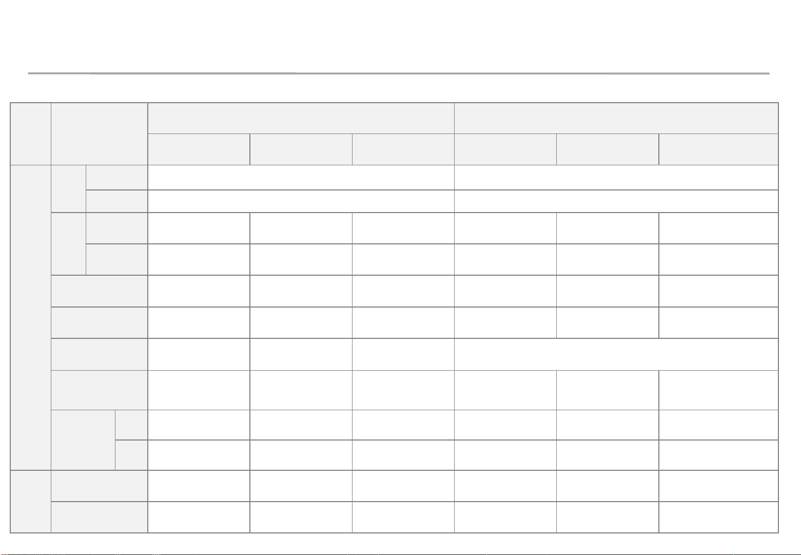
◇ Model specification
Spec
IER / IFR IER-F / IFR-F
P2.0 P2.5 P4.0 P2.0 P2.5 P4.0
Cabinet
Size
Width
960 240
Height
540 540
Resol
ution
Vertical
480 384 240 120 96 60
Horizontal
270 216 135 270 216 135
LED / Cabinet
(Pixel)
64,800 82,944 32,400 16,200 20,736 8,100
Module / Cabinet
12 12 12 3 3 3
Weight(Cabinet)
IER : 12.4kg
IFR : 12.4kg
IER : 10.8kg
IFR : 12.4kg
IER : 10.8kg
IFR : 12.4kg
3.2kg
Power
consumption
(W)
IER : 180W
IFR : TBD
IER : 150W
IFR : 260W
IER : 150W
IFR : 260W
IER : 60W
IFR : TBD
IER : 50W
IFR : 80W
IER : 50W
IFR : 80W
Max
number of
connection
(Set)
110V
IER : 3
IFR : TBD
IER : 4
IFR : 2
IER : 4
IFR : 2
IER : 10
IFR : TBD
IER : 10
IFR : 7
IER : 10
IFR : 7
220V
IER : 6
IFR : TBD
IER : 7
IFR : 4
IER : 7
IFR : 4
IER : 20
IFR : TBD
IER : 20
IFR : 15
IER : 20
IFR : 15
FHD
Screen
FHD
4x4, 16EA 5x5, 25EA 8x8, 64EA 16x4, 64EA 20x5, 100EA 32x8, 256EA
UHD
8x8, 64EA 10x10, 100EA 16x16, 256EA 32x8, 256EA 40x10, 400EA 64x16, 1024EA
※ Installation with IER/IFR of same pitch is recommended.
1. Product Information and Installation Precautions
Page 10
Samsung Electronics
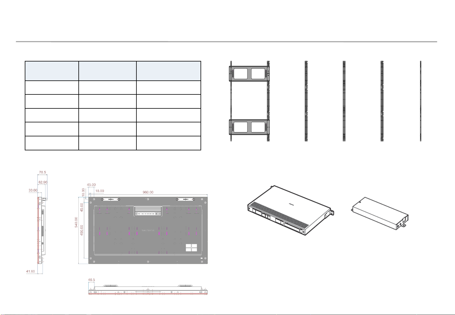
◇ Frame Kits configuration (See page 14.)
1. Product Information and Installation Precautions
Frame kit Configuration
for installation
Remarks
VG-LFR84FWL
8*4 (32 sets)
VG-LFR53FWL
5*3 (15 sets)
VG-LFR52SWL
5*2 (10 sets)
VG-LFR51PWL
5*1 P (15 sets) PIVOT installation
VG-LFR11SWL
1*1 (1 set)
Narrow
<5*3 Frame>
◇ Cabinet information
9
<S-Box> <I/G>
(Interface Gender)
◇ SNOW-1810U (S-Box, I/G)
※ Please refer to Appendix for information of IER-F / IFR-F Frame Kit
Page 11
Samsung Electronics
1. Product Information and Installation Precautions
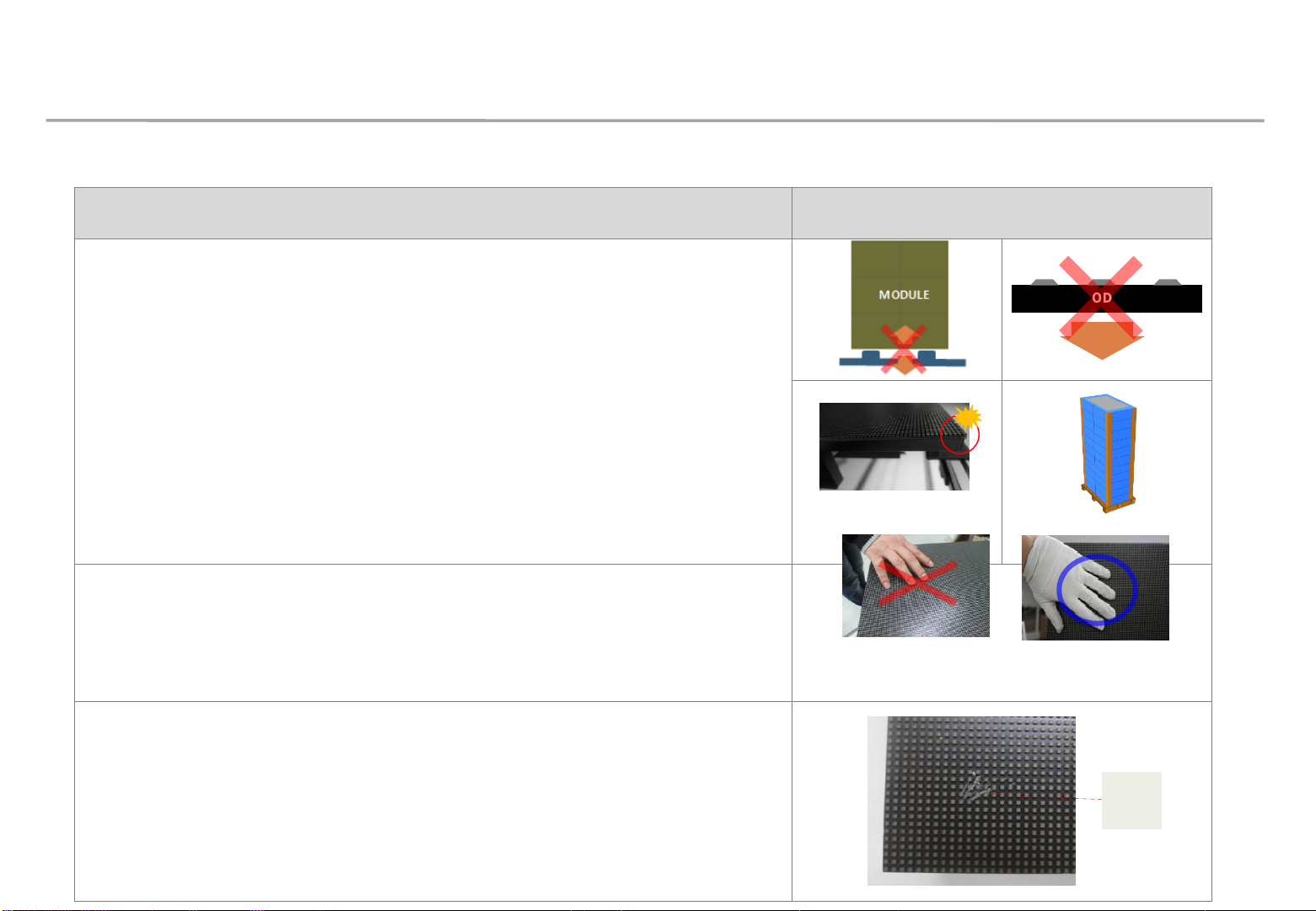
◇ Installation precautions (LED damage)
Precautions Images
[Be careful of external impact or dropping]
①
After removing the Cover-Corner from the product prior to installation,
exercise caution to ensure that the LED surface is not exposed to physical
impact and the product is not dropped onto the floor.
②
Do not place the product on a vibrating object. Make sure the LED surface
does not face down onto the floor.
③
Exercise caution to ensure that the corners of the LED module are not
damaged due to contact with external factors.
④
Make sure the number of loaded rows does not exceed 12.
①
②
③
④
[Be careful of LED damage due to static electricity]
▶
Do not touch the LED surface with bare hands without anti-static gloves.
[Be careful of LED damage due to metallic foreign material]
▶
Exercise caution to ensure that metallic foreign material is not attached to
the LED front.
▶
If metallic foreign material is attached, remove the module and use a
magnet to remove the foreign material.
MODULE
Front
Metallic
foreign
material
10
Page 12
Samsung Electronics
1. Product Information and Installation Precautions
11
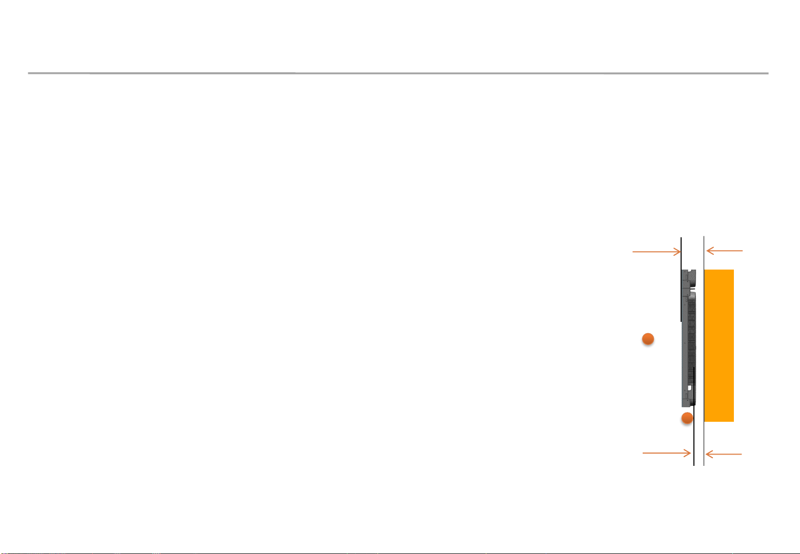
◇ Heat protection guide
Requirements for indoor installation
- Applicable to use of SAMSUNG wall mount (compliant with ADA)
∙ Gap between the product front and the wall: 99.5 mm
∙ Gap between the product rear and the wall: 35.5 mm
- Entry of sunlight
∙ If sunlight enters through glass windows or outer walls of the building,
contact Company HQ for assistance.
- Cold/warm air from HVAC system
∙ Make sure cold or warm air (especially warm air) from an HVAC system
does not reach the product.
- Outdoor temperature measurement position
∙ Center of the product or the inlet area
※ ADA: Americans with Disabilities Act
99.5 mm
35.5 mm
wall
Outdoor temperature
measurement position
Outdoor temperature
measurement position
※ This page is written based on the Full white,
650 nit (back light 7) version
Page 13
Samsung Electronics
1. Product Information and Installation Precautions
12
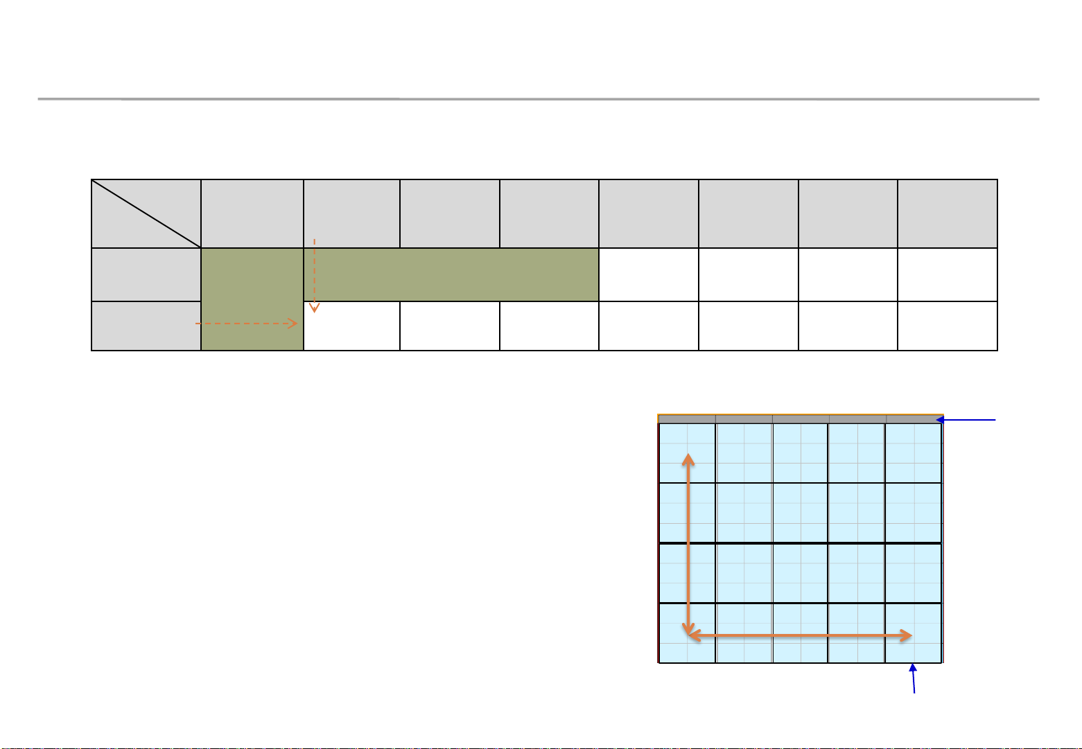
Fan flow rate depending on the number of installed cabinet rows
No. of rows
Outdoor
air temp.
1 to 3
Rows
4 Rows 5 Rows 6 Rows 7 Rows 8 Rows 9 Rows 10 Rows
Below 25℃
Fan
is not
necessary
Fan is not necessary
70 80 90 100
25℃ to 30℃
70 80 100 110 130 145 160
※ CFM = cubic feet per minute
※ Example) If outdoor air temperature is 30℃ and cabinets are
arranged in a 5x4 (horizontal x vertical) configuration,
what is the total CFM ?
→ 70 [CFM/column] x 5 [column]=350 [CFM]
5 Columns
4 Rows
Total minimum flow rate 350 CFM
70 CFM 70 CFM 70 CFM 70 CFM70 CFM
※ For installation under other conditions not covered in this guide, contact the Development Team.
Air vent area
FAN
※ Measurement based on one column
Outdoor air
temperature is
30℃
Page 14
Samsung Electronics
1. Product Information and Installation Precautions
13
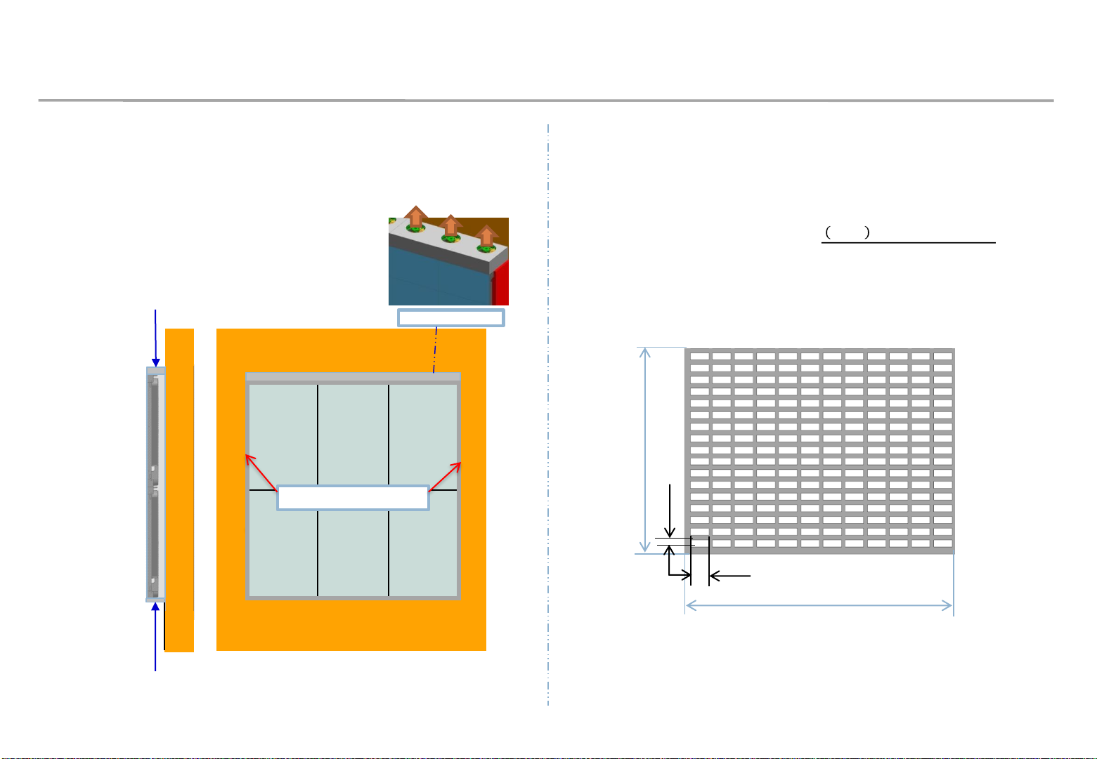
Requirements for using FAN
- Air vent: Should only be installed on the bottom
- Upper portion: Seal the entirety,
except the fan outlets
Shape of FAN unit
WALL
Location of FAN
Air vent area
Seal the left and
right sides
A
B
d
c
Vent requirements
- Use vents with an opening rate of at least 70%
- Opening rate (%) =
𝑐 𝑋 𝑑 𝑋 𝑁𝑜. 𝑜𝑓 𝑣𝑒𝑛𝑡 ℎ𝑜𝑙𝑒
𝐴 𝑋 𝐵
Seal the left and right sides
Page 15
Samsung Electronics
1. Product Information and Installation Precautions
14
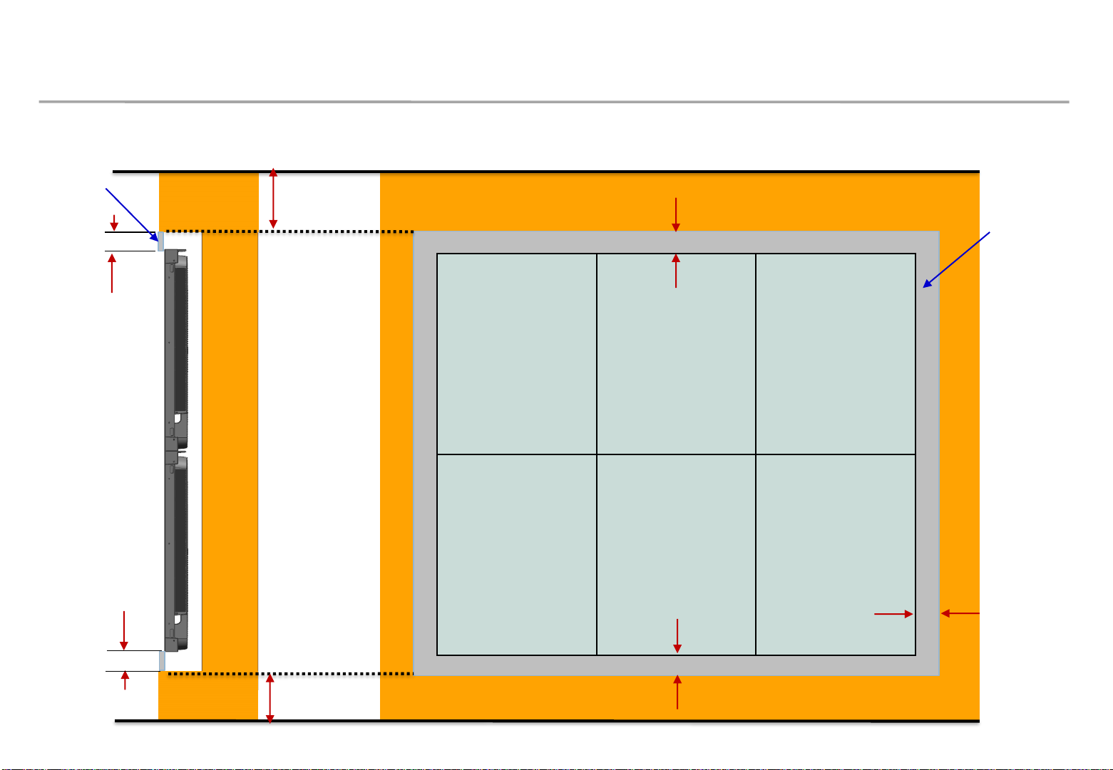
Minimum gap for embedded installation (Applicable when a fan is not used)
Min. 60 mm
WALL
Min. 60 mm
Air vent area
Min. 60 mm
Min. 60 mm
Min. 60 mm
Air vent area
Min. 300 mm (floor)
Min. 500 mm (ceiling)
Page 16
Samsung Electronics
1. Product Information and Installation Precautions
15
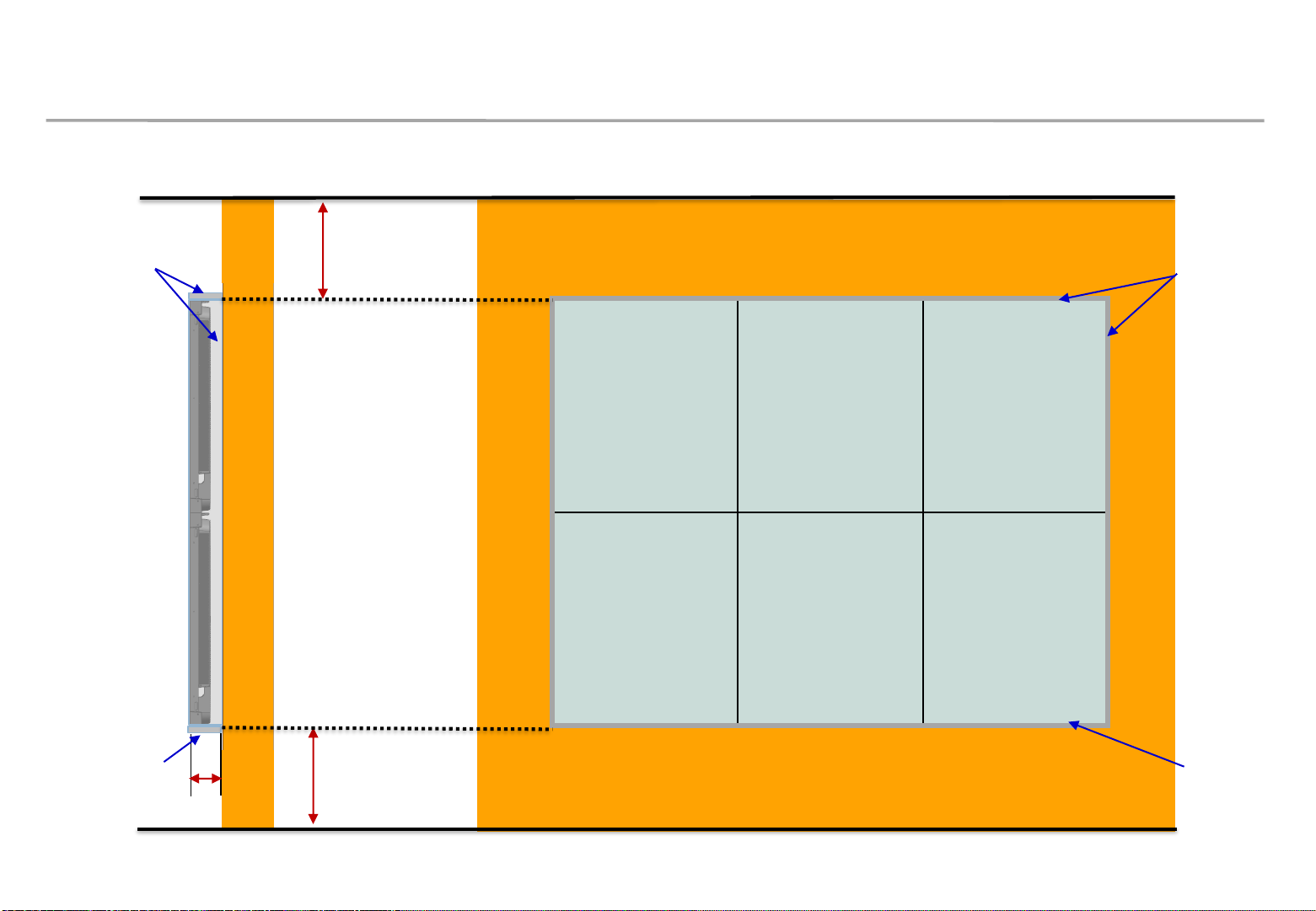
Minimum gap for installation on wall(Applicable when a fan is not used)
WALL
Min. 90 mm
Min. 300 mm (floor)
Min. 500 mm (ceiling)
Air vent area
Air vent area
Air vent area
Air vent area
Page 17
Samsung Electronics
1. Product Information and Installation Precautions
16
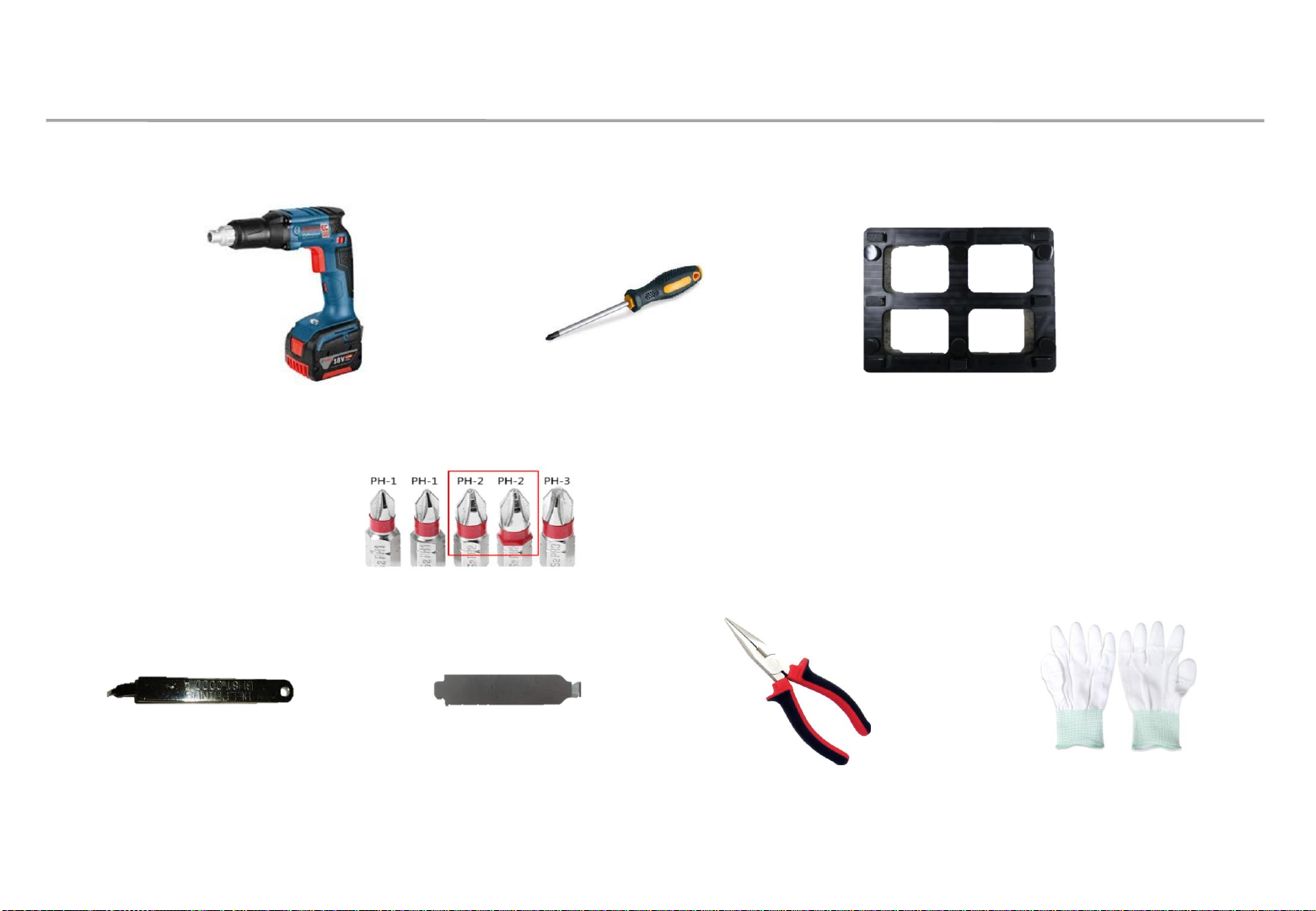
◇ Preparation for installation
LED MODULE JIG
(model name: CY-LJRNLS)
Electric screwdriver
Phillips (+)
screwdriver
Pliers
Service JIG
(BH81-00001A)
Holder Magnet Tool
Anti-static
gloves
※
Recommende
d sizes
Page 18
Samsung Electronics
2. Preparation for Cabinet Installation
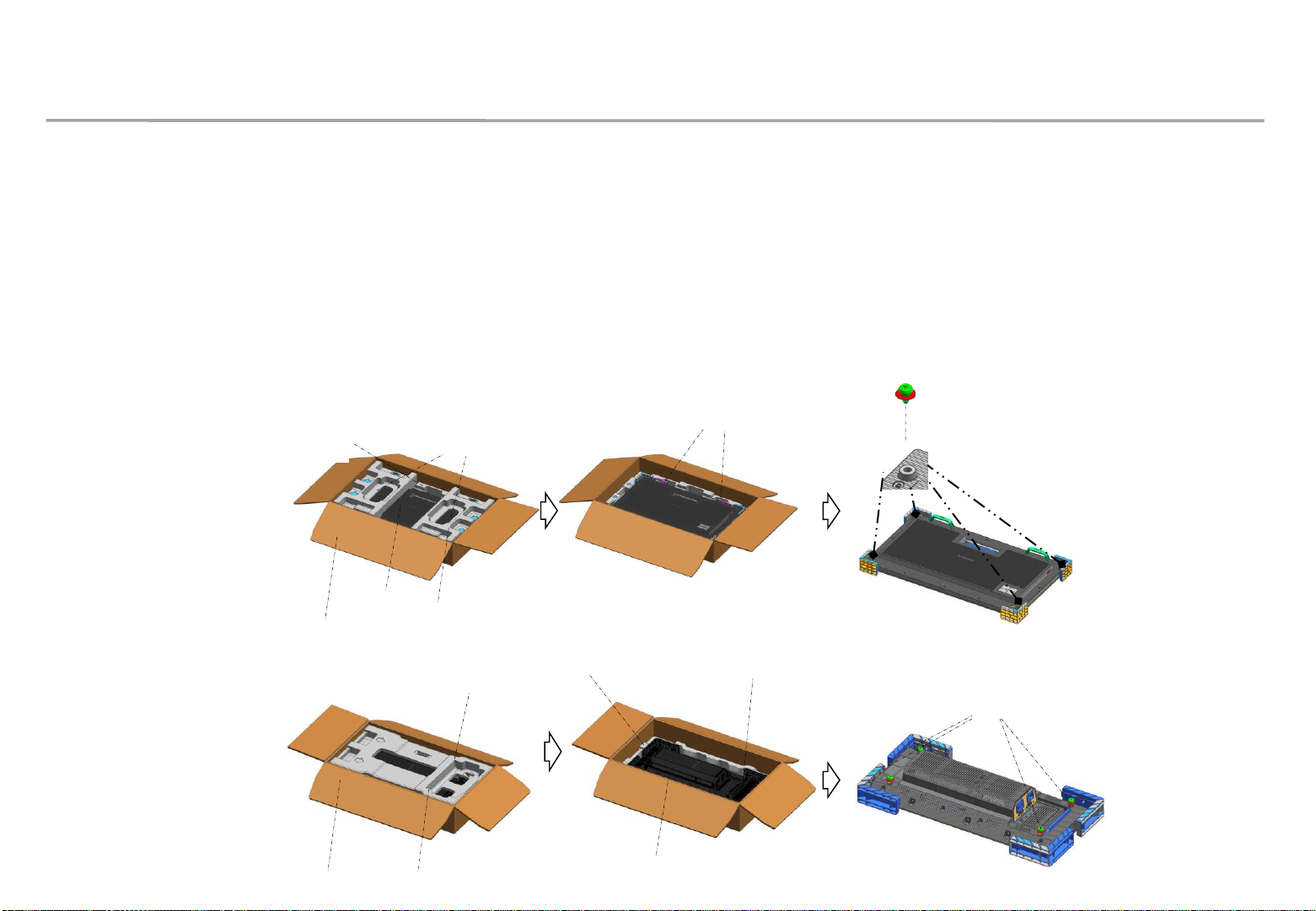
◇ Preparation prior to installation
① Remove the tape on top of the package box and open the box. (See Fig.1.)
② Remove the Top–Cushion and open the shielding bag. Hold the handles inside, take out the set, and then remove the PE bag.
(See Fig.2.)
③ Check that the sliding bolts are properly fastened. (See Fig.3.)
Fig.1 Contents of the
package
Fig. 2 Opening the
package
Fig.3 Checking the bolts
handl
e
TopCushio
n
IB &
cable
BottomCushion
LED
set
Box
SLIDING BOLT
Handle Shape
Top-Cushion
IB & cable
Bottom-Cushion
LED set
Box
SLIDING
BOLT
■ IER
■ IER- F
Page 19
Samsung Electronics
2. Preparation for Cabinet Installation
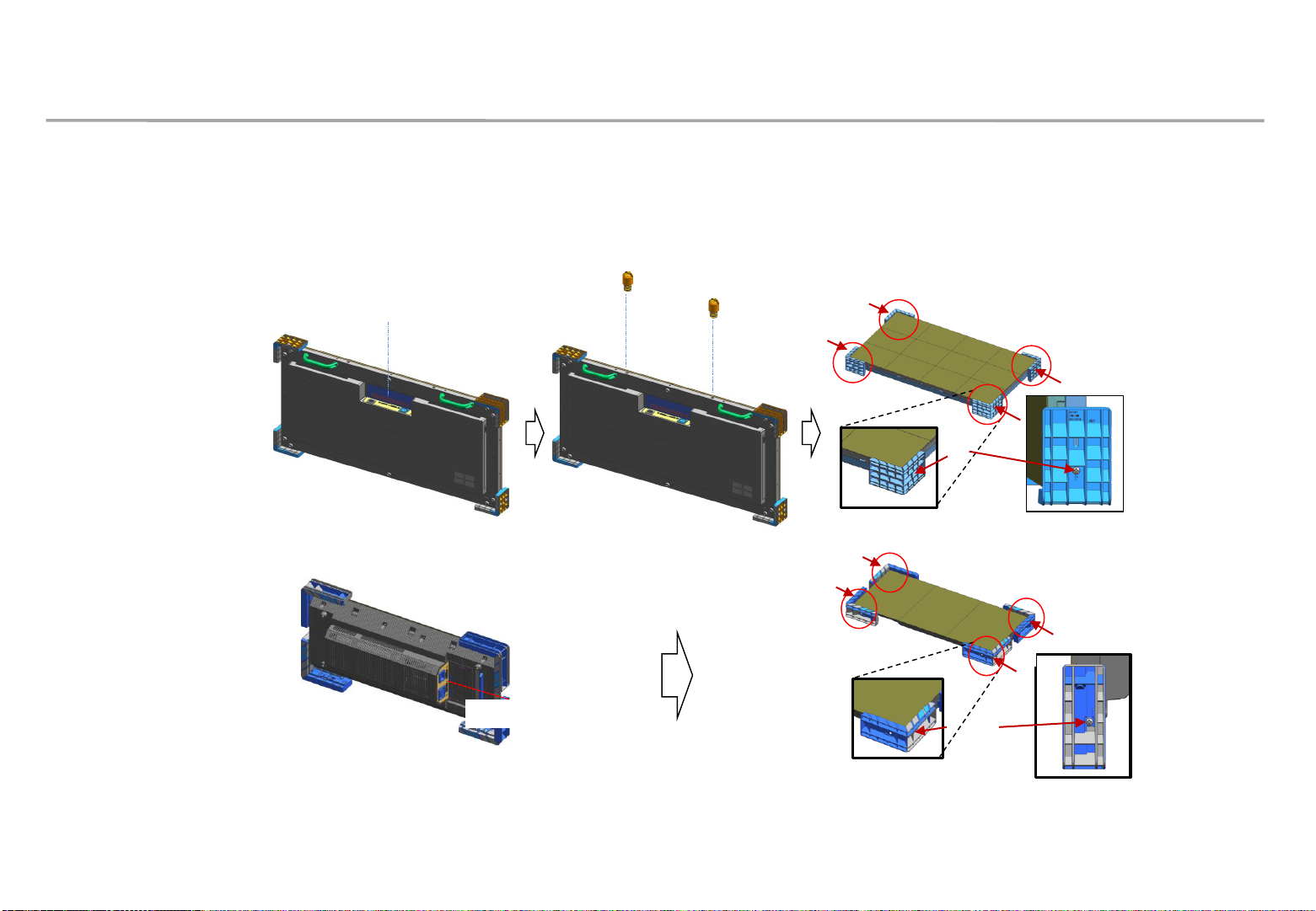
④ Connect the power and check for a problem with the screen. (See Fig.4.)
※ See page 12 for details on how to check for a screen problem.
⑤ Unfasten the screws (four screws in total) and remove the corner covers. (See Fig.5.)
Fig.4 Checking the screen
Fig.5 Removing the corner covers
18
Switch Button
S
C
R
E
W
Guide
Pin
Switch Button
SC
RE
W
■ IER
■ IER- F
Page 20
Samsung Electronics
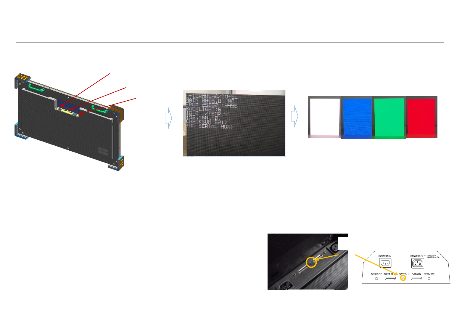
◇ Connect the power cord that came with the product and turn on the product.
Check that there is no LED damage and no problem is found on the screen.
※ Steps to perform in the event of White Pattern
- Apply power and press and hold the Switch for 5 seconds.
- When the factory info window appears, press the Switch once again.
- When the color screen appears, press the Switch repeatedly to check for malfunctioning LEDs.
(Each time the Switch is pressed, the LED color is switched in the following order:
white → blue → red → green.)
- To turn off the mode, press and hold the Switch for 5 seconds again.
Switch Button
Power In
Power Out
2. Preparation for Cabinet Installation
7
◈ Note: Checking for a screen problem
Switch
IER IER-F
Page 21
Samsung Electronics
2. Preparation for Cabinet Installation
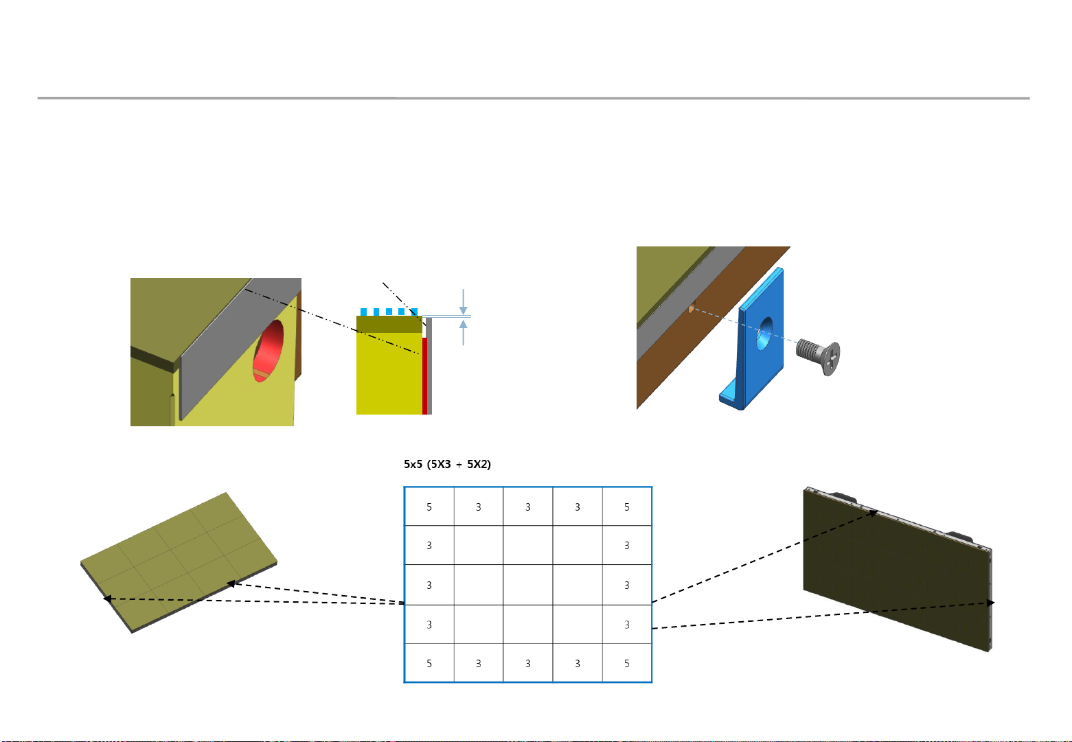
⑧ For cabinets placed on the edge, attach PET sheet before attaching PCB covers.
※ Attach PET sheet to all borders of the LED module (Fig.1), and attach PCB covers to the same outer sides where the
PET sheet has been attached (horizontally 5 points and vertically 4 points, as shown by the blue borders in Fig.2).
※ Attach PET sheet as shown in Fig.3. Make sure the area with no tape guides the LED module.
※ Attach PCB covers as shown in Fig.4.
Fig.2 Borders requiring PET sheet and PCB covers
* Numeric figure: Quantity of PCB covers to attach
Fig.3
Fig.4
PET sheet
No tape
0 to 0.5 mm
20
Fig.1 Attach PET sheet here
Fig.1 Attach PET sheet here
Page 22
Samsung Electronics
3. Frame Installation
21
a
a
b
b
c
b
d
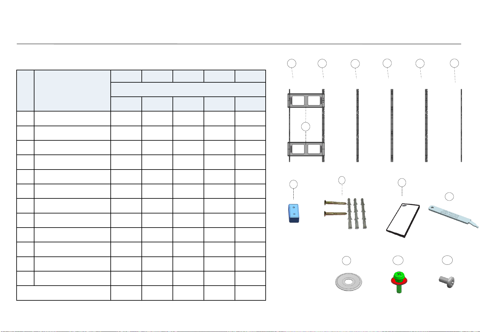
No. Item
VG-LFR84FWL VG-LFR53FWL VG-LFR52SWL VG-LFR11SWL VG-LFR51PWL
Qty (+spares)
8X4 5X3 5X2 1X1 PIVOT
ⓐ
ASSY BRACKET SIDE
2 2 2 2 2
ⓑ
ASSY BRACKET MIDDLE
6 3 3 - 3
ⓒ
ASSY BRACKET CENTER
1 (+1) 1 (+1) 1 (+1) - 1 (+1)
ⓓ
ASSY BRACKET JIG
2 2 2 - 1
ⓔ
JOINT V
10 7 7 2 7
ⓕ
ASSY ANCHOR SCREW
50 28 21 4 14
ⓖ
QUICK INSTALL GUIDE
1 1 1 1 1
ⓗ
Service JIG 1 1 1
- -
ⓘ
Wrench 1 1 1
1 1
ⓙ
WASHER (SLIDING BOLT) 10 5 5
- -
ⓚ
BOLT – ETC - - -
- 12
ⓛ
SCREW (M4) 20 14 14
4 14
Screen size for installation (mm)
7680X2160 4800X1620 4800X1080 960X540 2700X2880
① Make sure none of the following Frame Kit contents are missing.
g
f
M5, L65, Anchor Screw
h
Service JIG
e
JOINT V
j
WASHER
k
BOLT-ETC
QSG
l
SCREW (M4)
※ Refer to attachment at last page for IER-F installation
Page 23
Samsung Electronics
a
a
b
b
c
b
d
3. Frame Installation
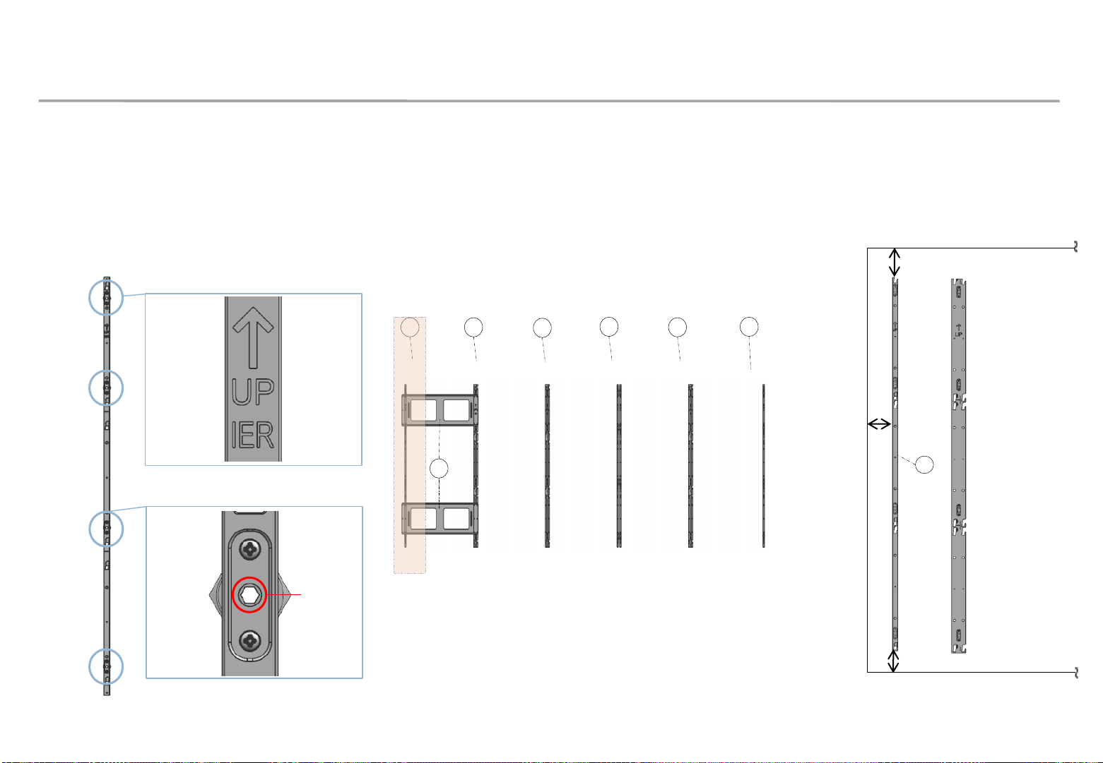
② On the left end, place the ⓐBracket Side and fasten the screws to install the Bracket (Fig.3).
※ Fasten one screw first, and use a clinometer to vertically align the right edges and fasten screws into the other holes.
(See the next page for precautions when fastening screws.)
Fasten the screws in the order of screw 1 → screw 2 → screw 3. Fig.1
ⓐ Fix the Bracket Side, following the measurements shown in Fig.4.
Fig.1 Order of fastening the screws
Fig.3 Positions of
components to attach
22
Fig.4 Screw fastening position
based on screen
12 mm or above
25 mm or above
12 mm or above
a
Fig.2 Screwing hole
Screwing
hole
①
③
③
②
Page 24
Samsung Electronics
3. Frame Installation
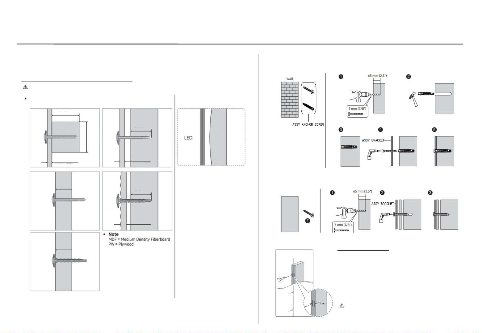
※ Precautions when tightening screws
23
Frames can be installed on a sufficiently thick concrete or interior wall.
Refer to the following figures.
If installing frames on a wall that is
not flat, irregular openings may
develop and affect the exterior
appearance.
• Make sure you check the location of the wood stud inside the
wall before screwing screws into the wall.
• Minimum wood stud size: 51 x 102 mm (2 x 4 inches)
Drill holes (3 mm) before screwing screws into the wall.
• Make sure you drill screw holes in the middle of the wood stud.
• If you screw a screw directly into the wood stud without drilling
a hole, the wood may crack.
• Standard wood stud interval of 16” is supported. (24” is not
supported.)
Samsung Electronics is not responsible for problems
caused as a result of failure to follow the requirements
specified in the installation guide.
Installation requirements
Standard installation requirements by wall type
Check the wall type before installation.
• First check the wall specifications (e.g.
type, thickness, floor plan).
① Sufficiently thick concrete or design wall
② Wood stud inside a plaster board, or MDF wall
Wall
Equipped with
stiffeners, e.g. MDF
or PW (plywood)
MDF, PW (plywood)
MDF, PW (plywood)
MDF, PW (plywood)
At least 10 mm
At least 50 mm
At least 30 mm
At least 10 mm
At least 30 mm
At least 10 mm
MDF, PW (plywood)
At least 25
mm
At least 25
mm
MDF, PW (plywood)
(except the plaster
board thickness)
Concrete composite wall
(except the plaster board
thickness)
At least 50
mm
Art Wall
Concrete
Page 25
Samsung Electronics
3. Frame Installation
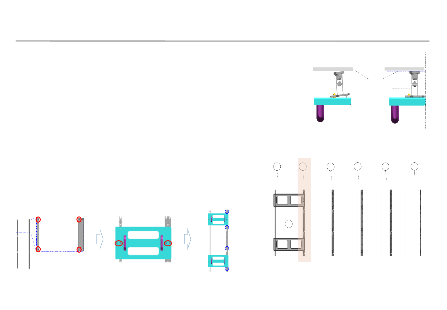
③ Install the ⓑ Bracket Middle.
※ First, check the holes into which to fix the ⓓ JIGs. (See Fig.1.)
※ Next, align the ⓓ JIG with the bracket holes and fasten the four screws. (See Fig.2.)
※ Lastly, fasten the screws to fix the ⓑ Bracket Middle to the wall. (See Fig.3.)
※ Caution: The surface ⓓ should be attached to ⓐ and ⓑ. The three surfaces (the wall,
ⓐ and ⓑ, and ⓓ) should be in parallel. (See Fig.4.)
④ Use the same steps above to install all ⓑBracket Middle,
in the left-to-right order.
※ Install the Bracket Center in the middle of the Frame Kit.
Fig1. Checking the holes
Fig2. Fixing the Jigs
(with screws)
Fig4. Keeping frames parallel
Fig3. Fastening the screws
Fig.5 Positions of components to attach
24
ⓐ,ⓑ,ⓒ
Wall
Incorrect
installation
Correct
installation
ⓓ
a
a
b
b
c
b
d
Page 26
Samsung Electronics
3. Frame Installation
25
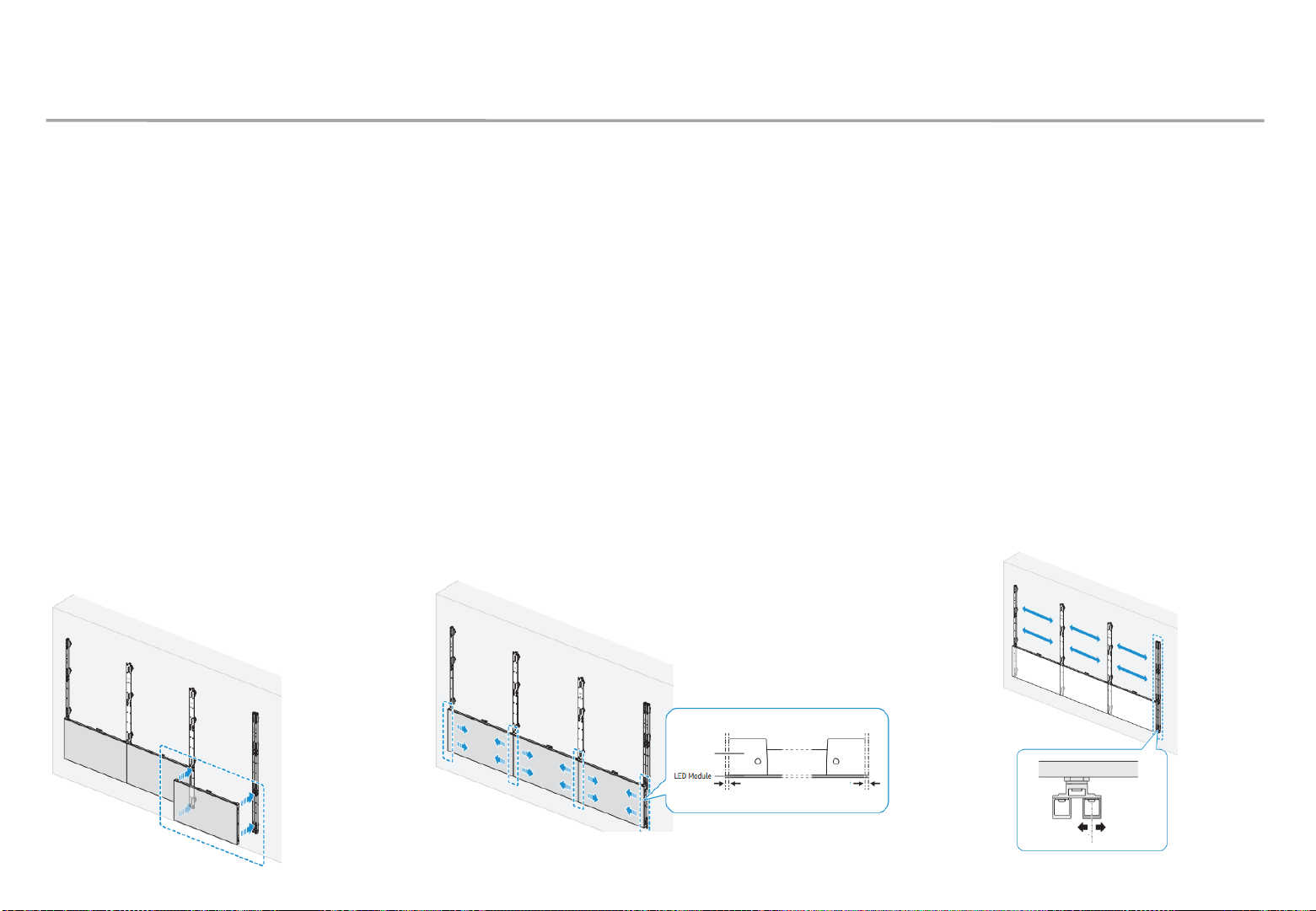
⑤ After installing the Bracket Center, install the lowest row cabinets. (See Fig.6.)
⑥ After installing the cabinets, push the LED modules toward the middle and check the height
difference between the cabinets on both ends and the LED modules. (See Fig.7.)
⑦ Roughly adjust the height difference between the left and right sides, and make fine adjustment
as shown below. (See Fig.8.)
• If the height difference is greater than 0.5 mm, move the frame outwardly.
• If the height difference is smaller than 0.0 mm, move the frame inwardly.
• Adjust height difference each time an additional cabinet is installed.
It is not necessary to adjust a height difference in the 0.0 to 0.5 mm range.
⑧ After adjustment is completed, install the ⓑBracket Middle.
(See step ② for details on how to install.)
⑨ Lastly, install the ⓐBracket Side.
Fig.7 Checking height difference
Fig.8 Adjusting height difference
Fig.6 Installing cabinets
Height difference
greater than 0.5 mm
Height difference
smaller than 0.0 mm
Height
difference
Height
difference
Cabinet
Page 27
Samsung Electronics
4. Frame Installation – Adjusting the Frame
Center (Important)
26
Fig.7 (check the gap) Fig.8 (adjust the gap)
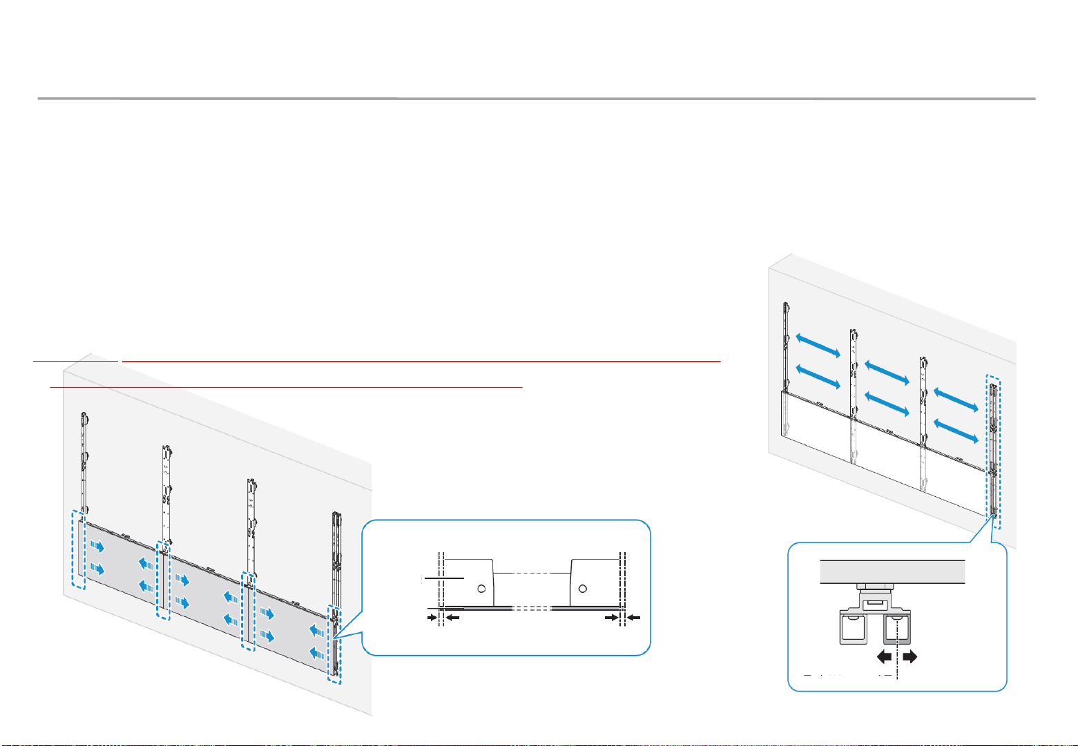
• Install the Frame Center after a Frame Side and two Frame Middles are installed based on the VG-LFR53FWL.
• Before installing Frame Middle next to the Frame Center, be sure to hang the IER Cabinet on the bottom line.
• Push the modules to the center and check the Frame Center so that there is no gap between cabinets and
between modules.
• When the module’s end is protruded more than 0.5 mm to the right based on the Frame Center, adjust the right
side of Frame Center outward.
• When the module’s end is protruded within 0.0 mm to the right based on the Frame Center, adjust the right side
of Frame Center inward.
• When installed long left to right, repeat the above procedure whenever a Frame Center is installed.
※ Otherwise, it may cause maintenance issues due to difficulty in attachment and detachment of a module.
Excessive attachment may cause the module’s dislocation. (see page 26)
◆Bracket Center’s usable section,
VG-LFR53FWL: Every 3 rows
VG-LFR52SWL: Every 3 rows
VG-LFR84FWL: Every 4 rows
LED Module
Gap is within 0.0 mm
Gap is over 0.5 mm
Cabinet
Gap
Gap
Page 28
Samsung Electronics
3. Frame Installation
27
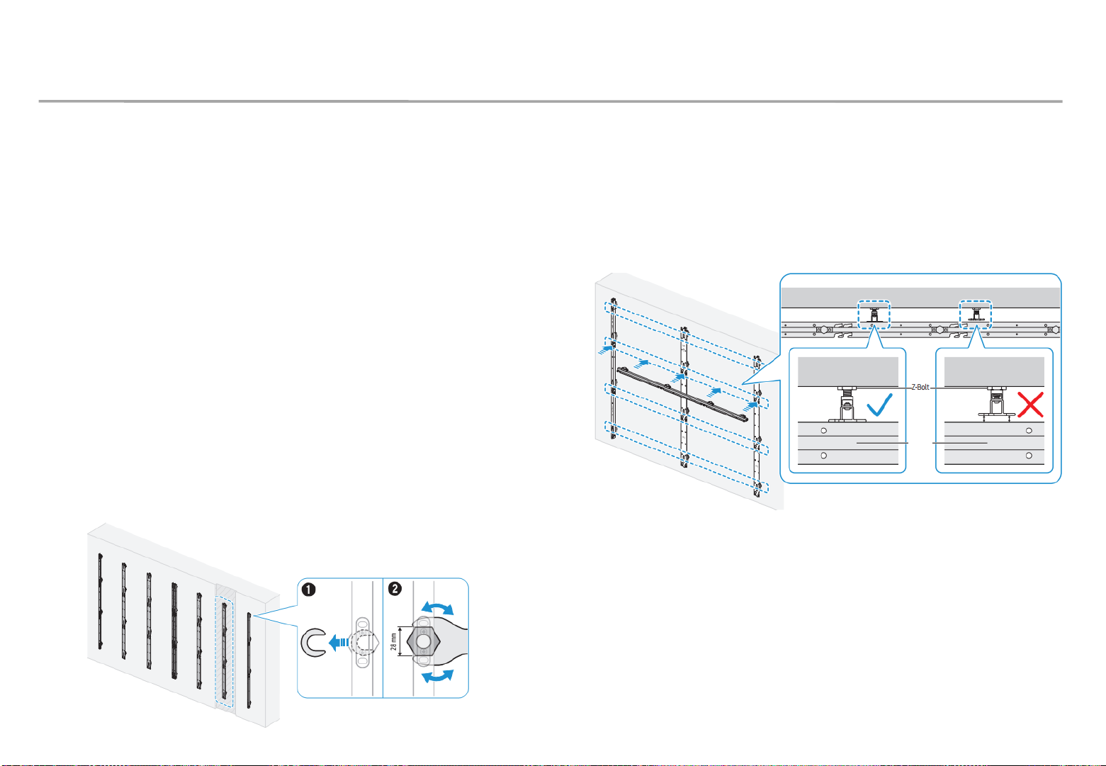
※ If installing three or more ASSY BRACKETs, adjust the flatness, because the wall or a
structure may cause warping.
– After installing three or more ASSY BRACKETs, put a spare ASSY
BRACKET horizontally and measure the height difference.
If a height difference is found, adjust the Z-Bolts of the ASSY
BRACKETs to adjust the flatness.
– How to adjust height
1. To adjust the height of a Z-Bolt of a frame, first remove the washer.
2. Use a 28 mm wrench to adjust the Z-Bolt height.
Flatness measurement positions:
Around areas where screws are fastened
Wall
Spare
frame
Wall
Wall
Page 29

Samsung Electronics
※ The Frame Kit product can be installed by extending the size as required.
- Components can be extended horizontally or vertically for installation.
- When installing ASSY BRACKET JIGs for fixing the joints between ASSY BRACKETs, make sure two persons work together so that the
ASSY BRACKET JIGs can be fixed properly.
(While one person holds an ASSY BRACKET JIG on the position to fix the JIG, the other person can fasten screws on the ASSY BRACKET JIG.)
- When performing extended installation, an ASSY BRACKET CENTER should be installed between the ASSY BRACKET MIDDLEs.
(It is recommended that one ASSY BRACKET CENTER be installed for three to four ASSY BRACKET MIDDLEs.)
28
3. Frame Installation
Page 30
Samsung Electronics
3. Frame Installation
29
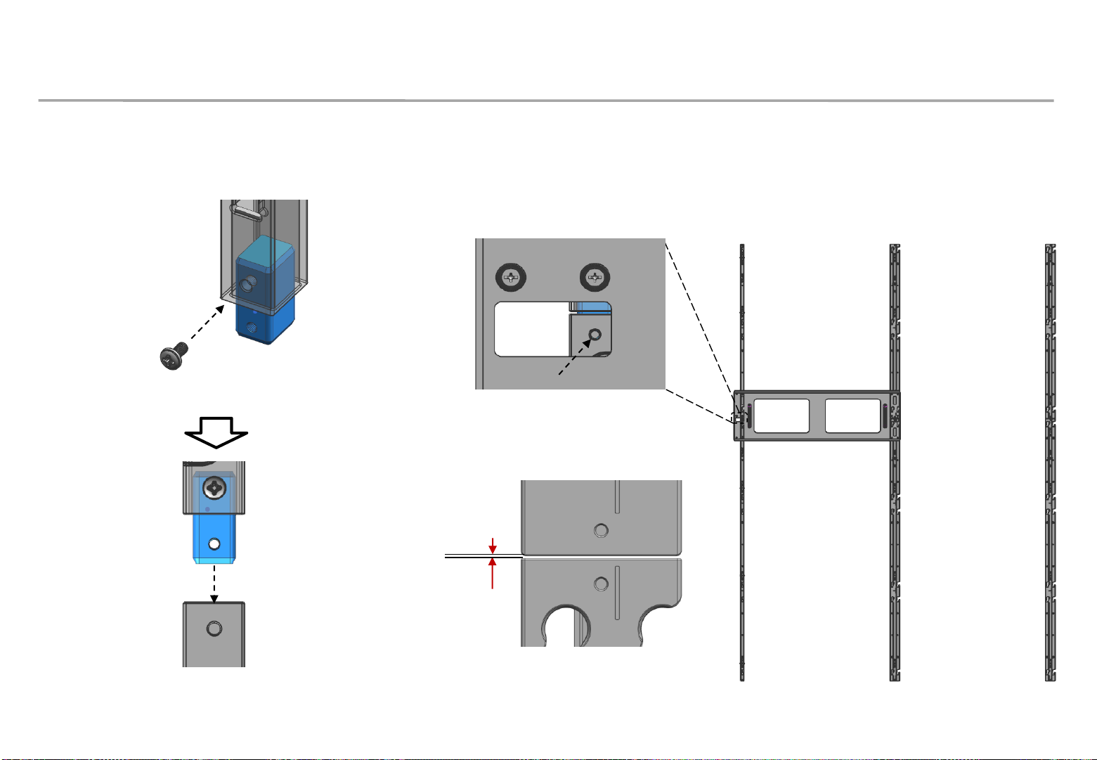
※ Vertical frame extension
-Attach the Joint V (vertical) to the target frame for extension
Fasten M4
<Vertical extension>
M4 screw
- Insert the joints of the additional frame into the existing frame. Insert jigs
to place the frames into position.
- After attaching the jigs, fasten screws between the frames.
- Distance between connected frames for extension is 1 mm.
1 mm
* FRAME 연장시 수직, 수평이 틀어지기 쉽다. 연장하면서 수평 수직 CHECK 를 반드시 해야한다. ( 레이저 수평계 / 실 등)
Page 31
Samsung Electronics
4. Cabinet + Frame Installation
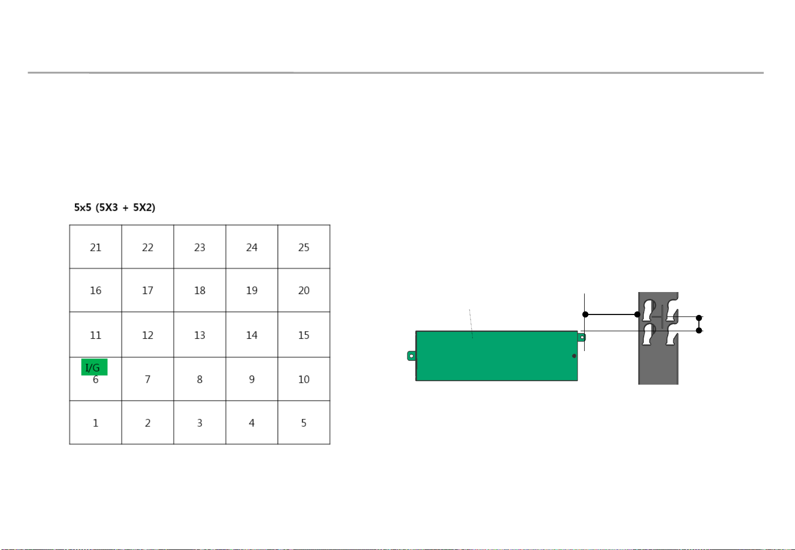
① Attach the I/G on the rear of each cabinet by type, first. (See Fig.1.)
※ Installation position: Place the I/G at a spot 35–40 mm below the engraving on the right-side frame, and fasten the screws (Fig.2).
35–40 mm
I/G
◇ Fixing of I/G position
Fig1. I/G attachment position / order of installing cabinets
Fig2. I/G attachment position
70–80 mm
30
Page 32
Samsung Electronics
4. Cabinet + Frame Installation
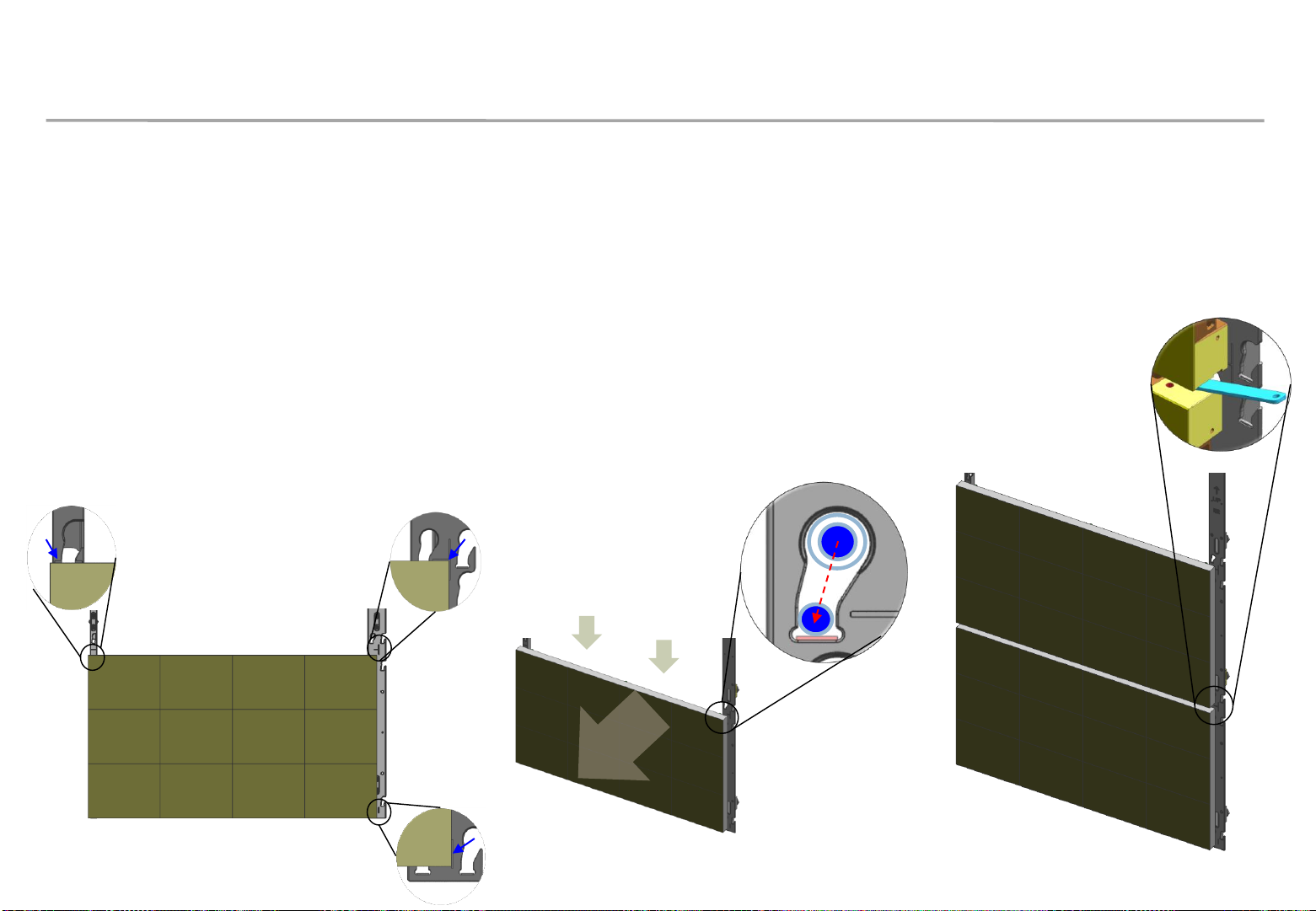
② Draw the cabinet right up against the frames by aligning the cabinet corners with the
engravings on the frames.
※ For the order of installing cabinets, see Fig. 1 on page 22 .
※ Check that the four bolts are all inserted into the frames. (See Fig.1.)
③ Push the top surface of the cabinet corners down so that the cabinet slides down diagonally.
(See Fig.2.)
④ From the second row and above, insert the Service Jig between the cabinets and attach
the cabinets. Next, remove the Service Jig and slowly lower the cabinets. (See Fig.3.)
※ Exercise caution to ensure that the Service Jig does not touch an LED module.
※ Each time a cabinet is installed, check that there is no inter-module gap or pitch interval warning found.
Display
unit
Display
unit
Fig.1
Fig.2
Fig.3
Sliding Screw
31
Page 33
Samsung Electronics
32
5. Cabinet + Frame Installation
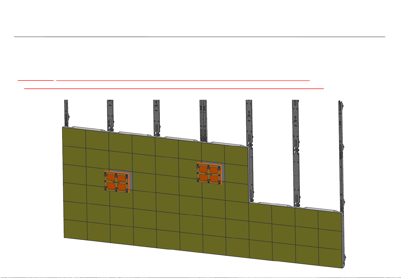
⑤ When modules are tightly coupled, it becomes difficult in detaching a module.
Accordingly, sample some modules during installation to check whether module
detachment is possible. ★Important
※ Otherwise, it may cause maintenance issues due to difficulty in attachment and detachment of a module.
Excessive action may cause damage to the module. Sampling is recommended for every 2- to 3-row cabinets.
Page 34
Samsung Electronics
4. Cabinet + Frame Installation
33
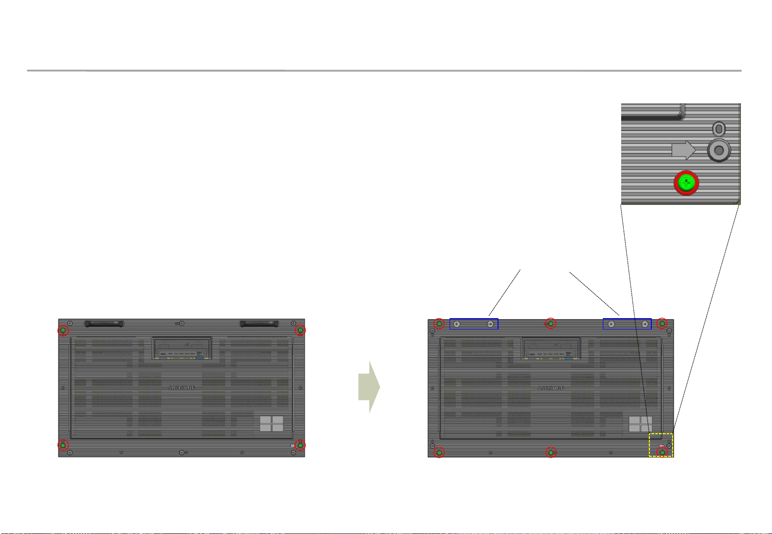
◇ PIVOT installation
Fig1. Positions of BOLT ETCs fastened in delivered product
Fig2. Positions to fasten BOLT ETCs when installing the PIVOT
When installing the PIVOT, use the PIVOT-specific Frame Kit.
(VG-LFR51PWL / the same installation steps apply)
① Check that the BOLT ETCs are fastened. (Fig.1)
② Fasten the BOLT ETCs again appropriately for PIVOT installation. Fasten
two additional bolts and remove the COVER HANDLEs. (Fig.2)
③ Install with the arrow pointing up, by referring to the engraving indicating
the direction.
Engraving indicating
the PIVOT direction
Remove the COVER HANDLEs
Page 35
Samsung Electronics
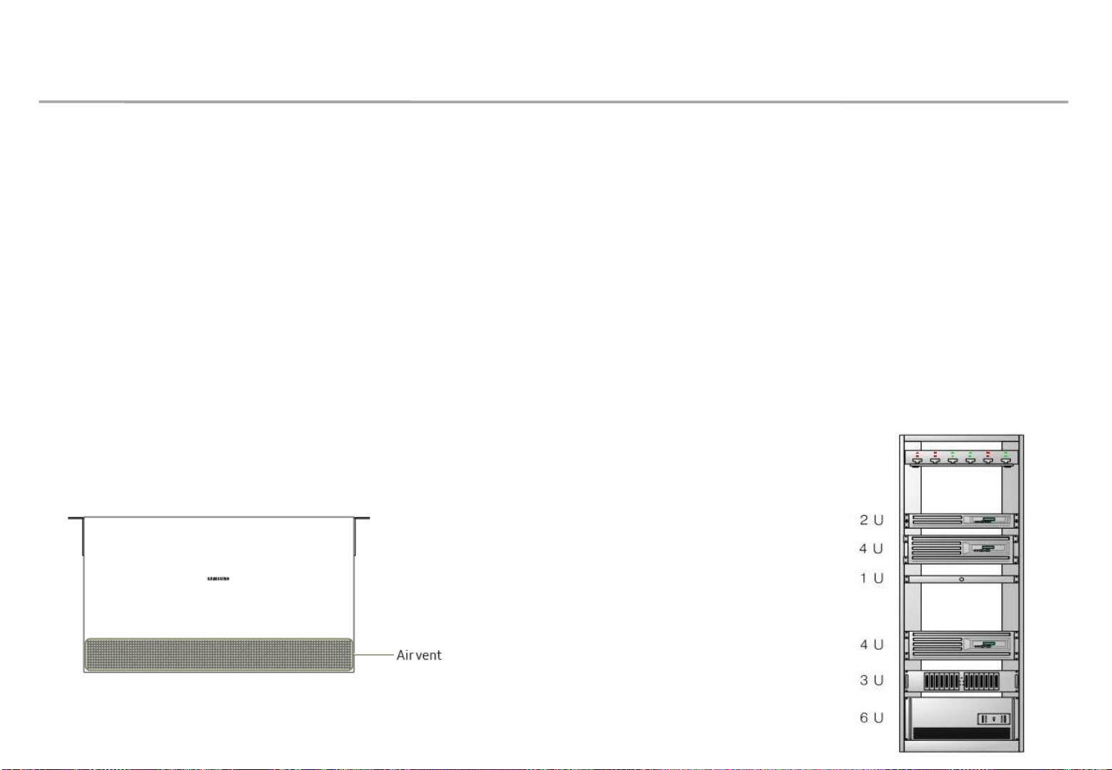
① Installing it in a 19-inch server rack is recommended.
② Make sure the air vent is open and not overturned or turned sideways.
③ Exercise caution to ensure that the air vent is not covered by an object. Covered air vent may cause overheating of
the product.
④ If installing multiple S-Boxes, make sure there is a gap of at least 1U (44.45 mm) from the product at the top.
⑤ If installing an S-Box onto a wall, make sure there is a gap of at least 10 mm between the wall and the top, bottom
and sides of the product. Make sure there is a gap of at least 50 mm between the cable ports and the wall to ensure
proper cable connection.
⑥ Maintain the residual heat inside the rack at a temperature below 35°C.
⑦ Exercise caution to ensure that no liquid enters the air vent of the product.
34
5. S-Box Installation and Connection
• Precautions for installing S-Box
※ When connecting two or more sets for Multi-link HDR, install them in the six-sided shield rack. (Only SBB-SNOWJMU)
Page 36
Samsung Electronics
• Use *STP and *FTP level cables better than 15–100 m long CAT 6
to ensure HDBT signal stability.
• Do not use CAT 6 UTP cables.
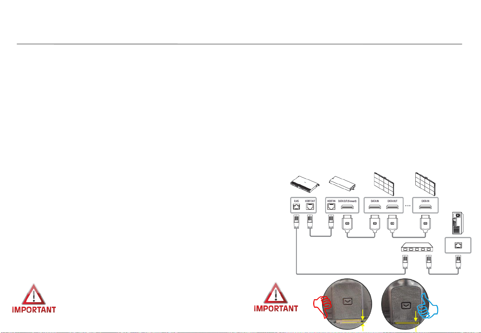
• Do not bend cables excessively.
• Do not bind multiple cables together.
35
5. S-Box Installation and Connection
• S-Box connection
① Send visual signal input into the S-Box (input ports: HDMI, DP).
② Use the SOURCE STATUS to check the signal input (Red: HDMI1, Green: HDMI2, Blue: DISPLAY PORT).
③ Use the LAN cable to connect the HDBT OUT port on the S-Box to the HDBT IN port on the Interface Gender.
④ Use the OCM cable to connect the DATA OUT port on the Interface Gender to the DATA IN port on the first cabinet.
⑤ Please add input signal with “Input signal Plus” menu for UHD resolution
※ Menu – Picture – Advanced Settings – Input signal plus : add input signal
(The default setting is OFF. If this setting is changed, the S-Box is rebooted.)
⑥ The screen is displayed based on the cabinet in the top left.
To view the screen, connect to the HDBT OUT1 port on the S-Box.
⑦ For each S-Box, the same type pitch cabinet can only be supported
simultaneously. When installing the product, only connect
compatible cabinets to the product.
Page 37
Samsung Electronics
36
5. S-Box Installation and Connection
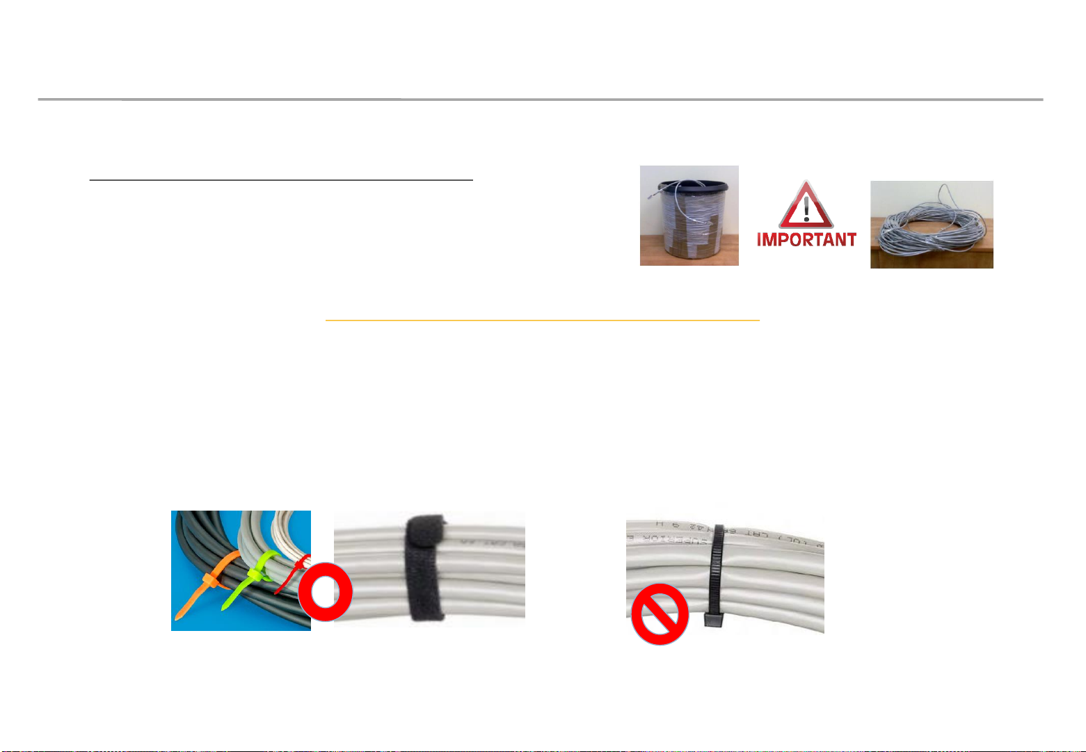
⑧ Cable recommendations for HDBaseT
Do not use “comb” or “pinstripe” type cables.
Use HDBaseT cables that are 15 m to 100 m long.
Use HDBaseT Cables recommended at the following Alliance website.
HDBaseT Alliance website: https://hdbaset.org/hdbaset-recommended-cables/
Do not bend HDBaseT cables to ensure signal consistency.
When organizing HDBaseT cables, make sure the cables are not tied too tight.
Do not bind HDBaseT cables and AC power cables together.
★ Orderly Rolled (Recommend) ★ Random Rolled
(Not Recommend)
Page 38

Samsung Electronics
5. S-Box Installation and Connection
EMI sources: Ensure that the product is placed away from the electromagnetic environment (e.g. high-voltage wires,
electric motor-based equipment such as an elevator or refrigerator, fluorescent lights, lighting fixture).
Keep a distance of at least 12” (=30.48cm) between HDBaseT cables and AC power cables.
A maximum of four cables connected to a single S-Box can be bounded together.
⑧ HDBaseT cable
Page 39
Samsung Electronics
5. S-Box Installation and Connection
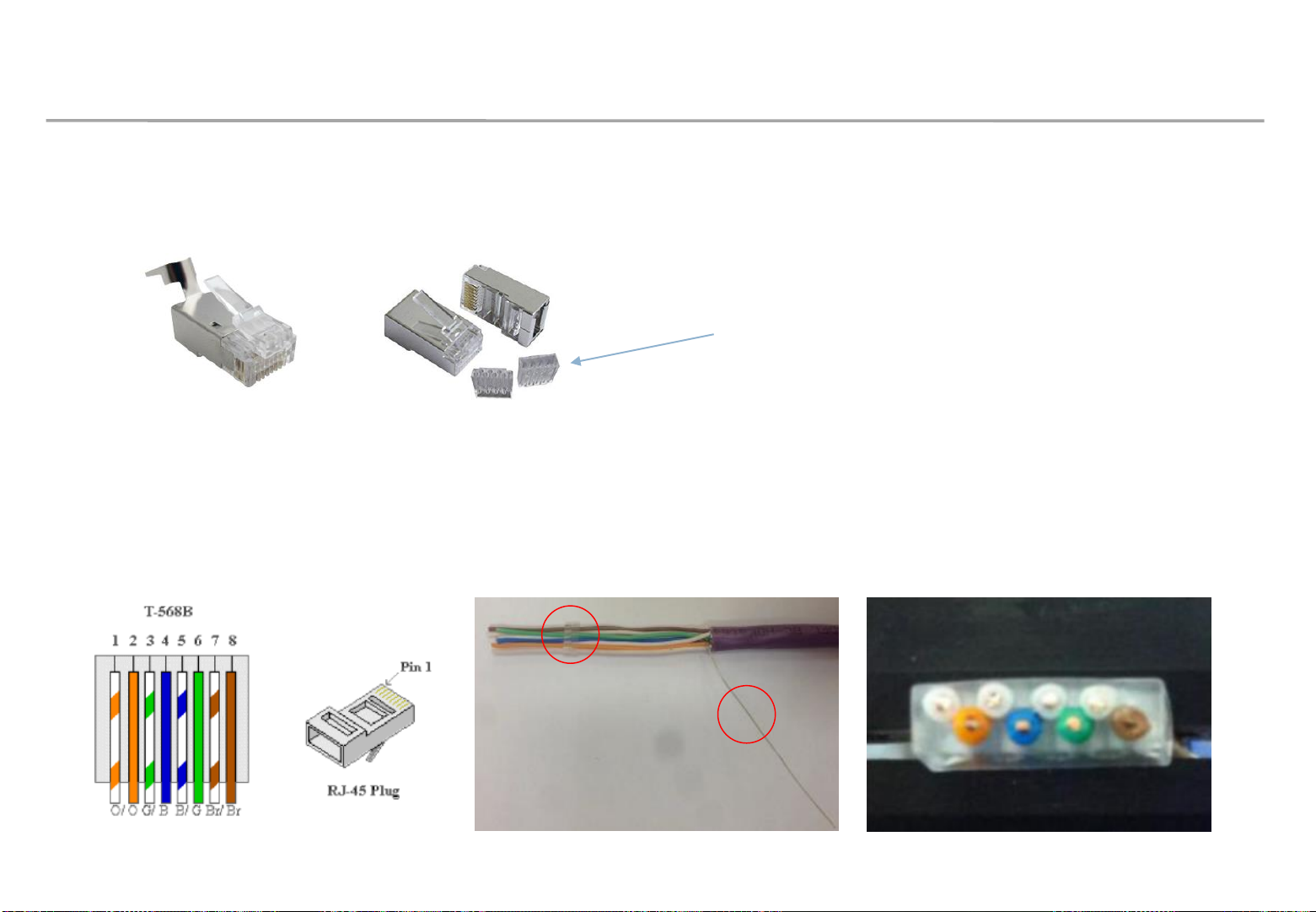
Using shielded STP RJ45: Use a shielded RJ45 connector, and a CAT 6 or CAT 7 connector using a plastic load bar.
Insertion of conductors (conducting wires) into plastic loader: Insert conducting wires into the RJ45 connector, as shown by
the conducting wire structure (T-568B) in the following figure. Plastic load bar is required. (The reason is that the thickness of a
CAT 6 cable prevents the cable from being placed flatly in an RJ-45 connector, unlike general CAT 5 cables.)
⑨ Finishing the HDBaseT cable after installation
Load bar
Wires aligned with load bar
Load bar and drain wires
Page 40
Samsung Electronics
5. S-Box Installation and Connection
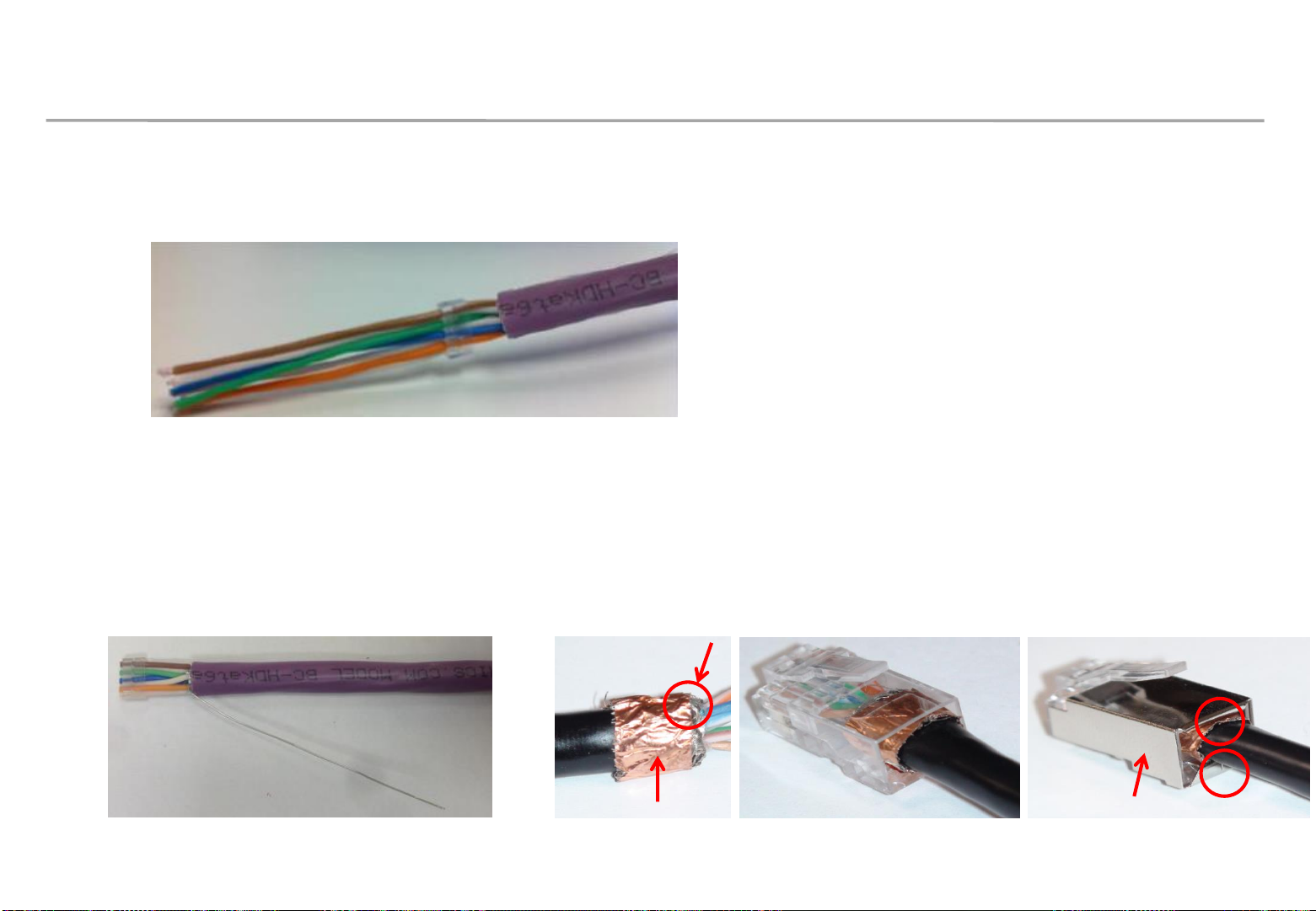
Pushing in of plastic loader to fullest extent: Push the plastic load bar as close as possible to the cable.
Use a wire stripper to cut all conductors (conducting wires) down to a length of about 0.5 inches.
⑩ Finishing the HDBaseT cable after installation
Case 1) With drain wire: Refer to the next page.
Case 2) Without drain wire: Use copper foil to contact the connector shell part,
as shown below.
Copper foil
Fold aluminum foil or braid back and wrap it with copper foil.
Connector shell
Page 41
Samsung Electronics
5. S-Box Installation and Connection
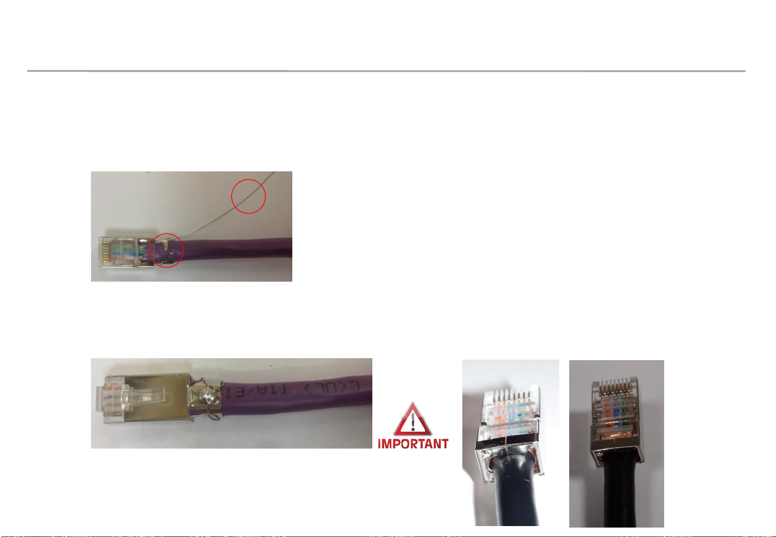
Fold and raise the drain wire above the RJ-45 connector. Use pliers to attach the deformation prevention parts together, as
shown below.
Soldering of drain wire to metallic part of RJ45 connector: Solder the drain wire to the metallic part of the RJ45
connector and cut unnecessary parts out. Use a cable tester to the conductors and shield status (continuity).
⑩ Finishing the HDBaseT cable after installation
Recommendation) Drain wire soldering + copper foil
Page 42
Samsung Electronics
41
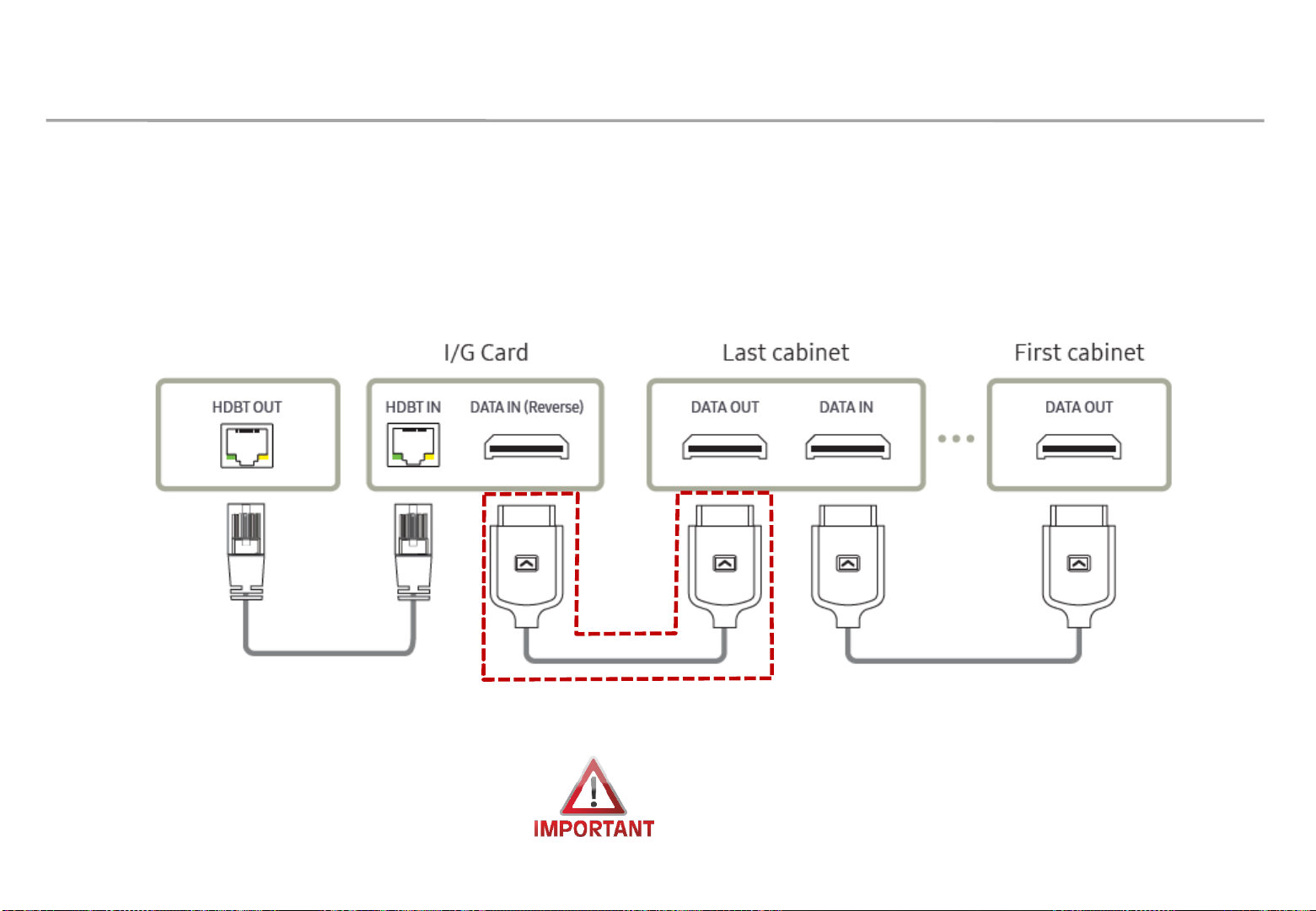
• S-Box Connection (Redundancy)
5. S-Box Installation and Connection
① If a redundancy feature is required
Use the OCM cable to connect the DATA IN port on the Interface Gender to the DATA OUT port on the last cabinet.
• Use 15–100 m long CAT 6 *STP and *FTP level cables
to ensure HDBT signal stability.
• Do not bend cables or bind multiple cables together.
SNOW-1801U
Page 43
Samsung Electronics
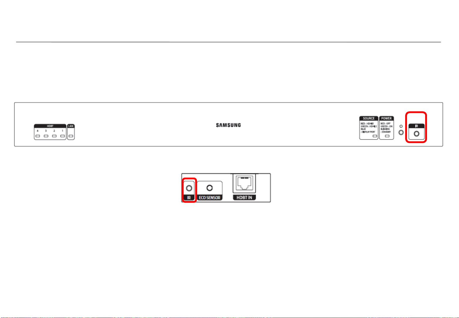
※ Only one external IR receiver is provided for a set.
- External IR receiver can be connected to the S-Box body or Interface Gender card (I/G card).
42
• S-Box Connection (External IR Receiver)
5. S-Box Installation and Connection
OR
※ When connected to the I/G card, make sure “Network Standby” is set to “On” in System - Power Control.
Page 44
Samsung Electronics
43
• S-Box Connection (Panel Configuration)
5. S-Box Installation and Connection
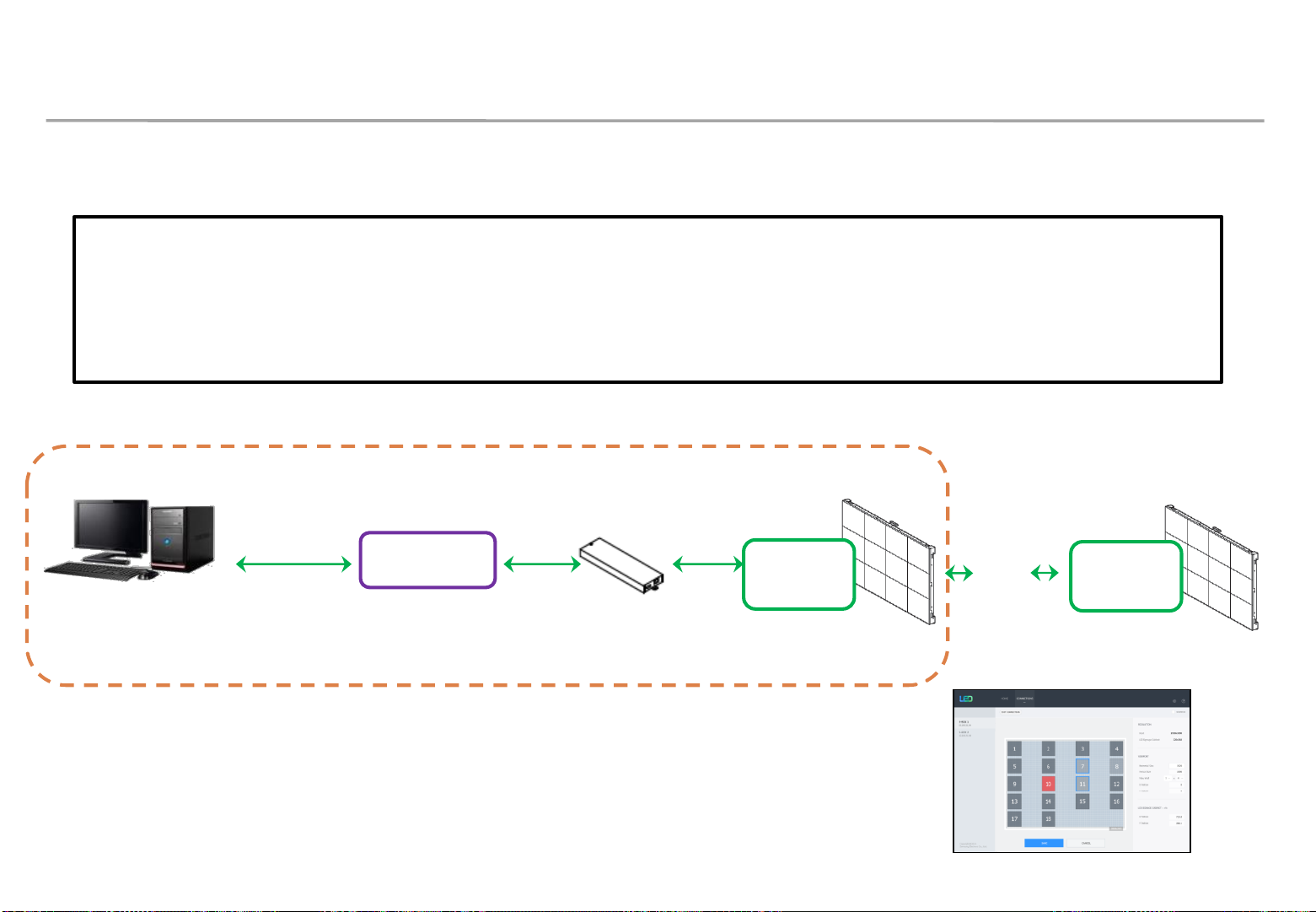
① Initial S-Box picture quality settings
• S-Box is delivered with default picture quality settings optimized for the IWJ cabinet.
• After an LED display is installed, the picture quality settings become automatically optimized for the installed LED display model.
• To ensure configuration of optimum picture quality settings, make sure you use the LSM SW to connect the S-Box to the LED display.
• Make sure the LED display is connected to HDBT Port 1.
• Picture quality settings are configured based on the master cabinet model connected to HDBT Port 1.
* If the S-Box is not connected to the LED display via LSM, displayed colors may not look natural.
<Connection screen>
Control PC
(LSM)
S-Box
Ethernet
Interface Gender
Vx1
……………
HDBT
Vx1+Ethernet
Cabinet 1
(Master)
Cabinet N
Page 45
Samsung Electronics
44
5. S-Box Installation and Connection
• S-Box connection (Grouping)
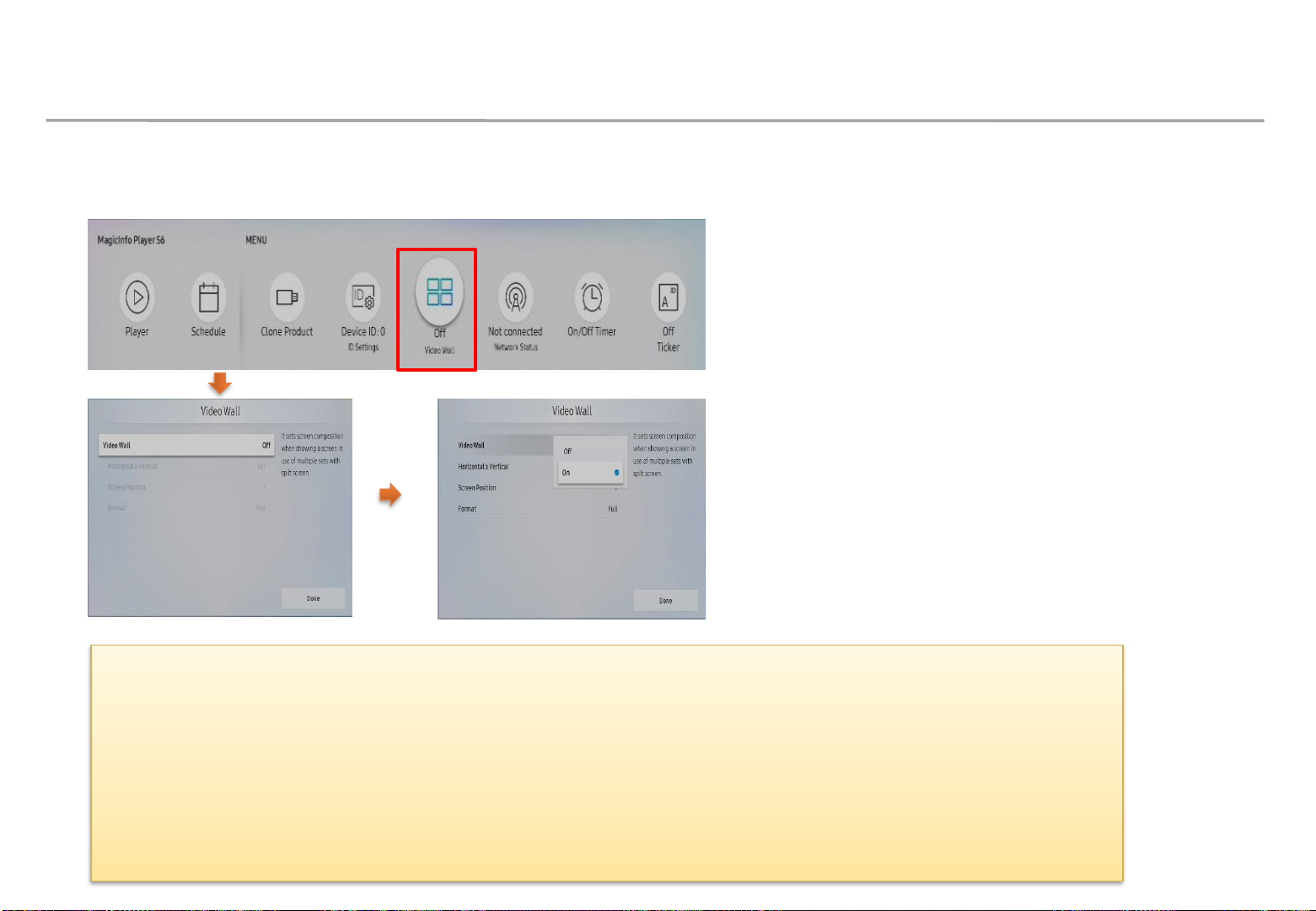
Press the Home button on the remote control and set Video Wall to “On”
[Precautions]
1) Prior to running S-Box Grouping from LSM (LED Signage Manager), make sure you set the resolution for
the input source device to a resolution compatible with S-Box Grouping.
2) If a resolution not compatible with S-Box Grouping is selected, a blank or static screen may be displayed. If
this is the case, turn off the Video Wall function and change the resolution for the video output source to 50
Hz or 60 Hz.
※ Since June 2013, the S-Box Grouping function has been provided through LSM. Check the latest LSM
version.
Page 46
Samsung Electronics
5. S-Box Installation and Connection
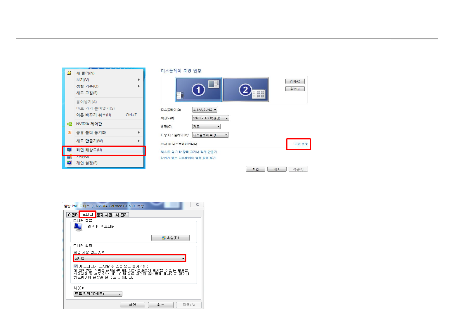
Right-click with the mouse on the computer desktop and click “Screen Resolution” → “Advanced settings.”
Click the “Monitor” tab and select “60 Hertz” from the “Screen refresh rate” dropdown box under “Monitor
Settings.”
③ Changing the PC output frequency
Page 47
Samsung Electronics
5. S-Box Installation and Connection
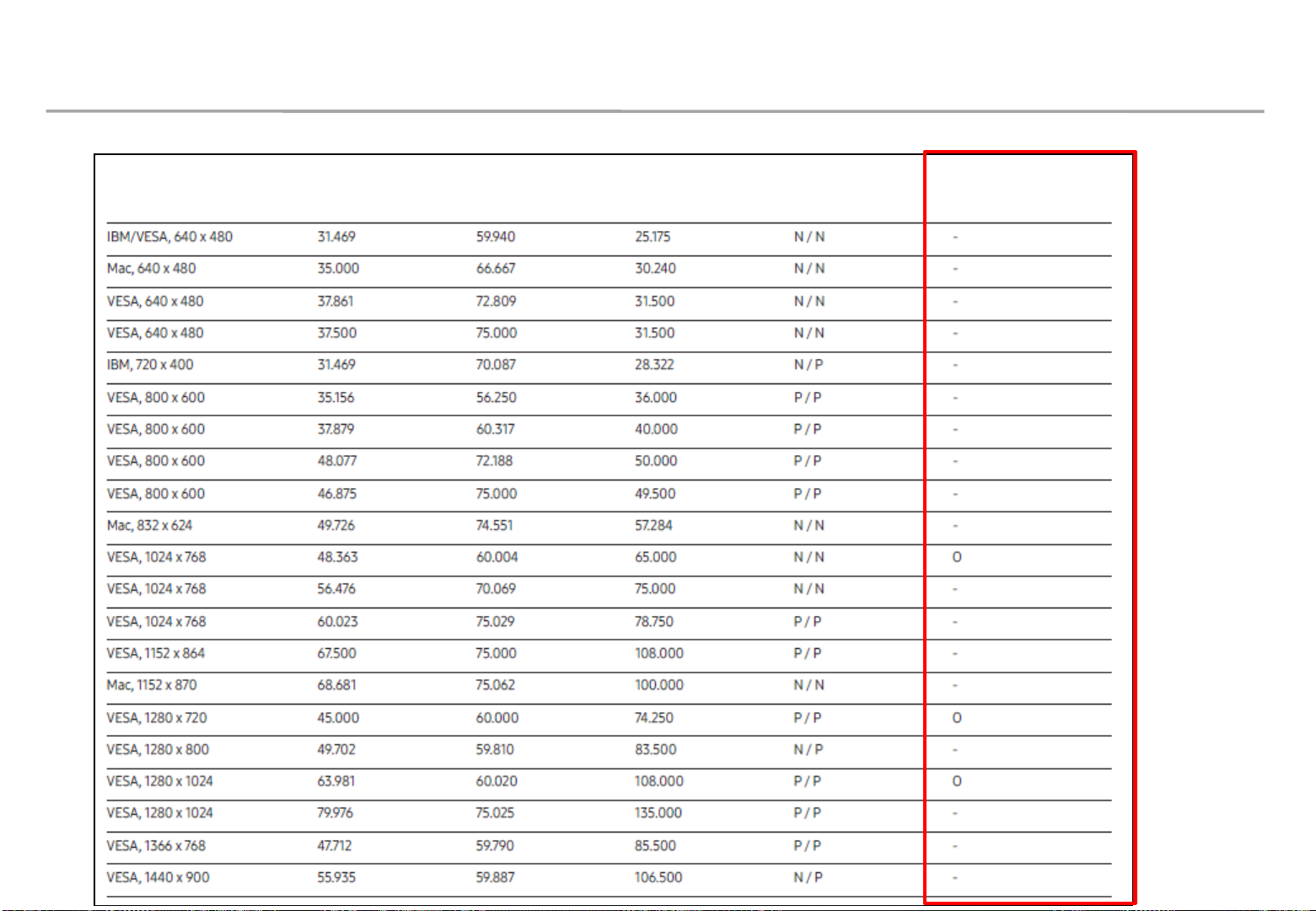
④ Frequencies compatible with S-Box Grouping (1/2)
Resolution Horizontal frequency Vertical frequency Clock frequency Polarity
(KHz) (KHz) (MHz) Horizontal / Vertical
S-Box Grouping
Page 48
Samsung Electronics
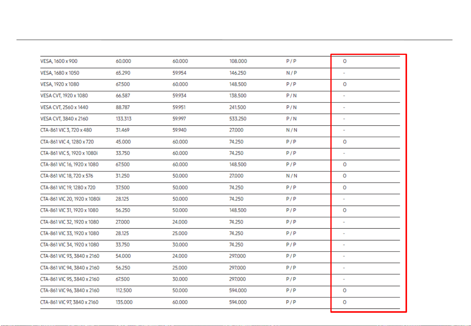
5. S-Box Installation and Connection
④ Frequencies compatible with S-box Grouping (2/2)
Page 49
Samsung Electronics
5. S-Box Installation and Connection
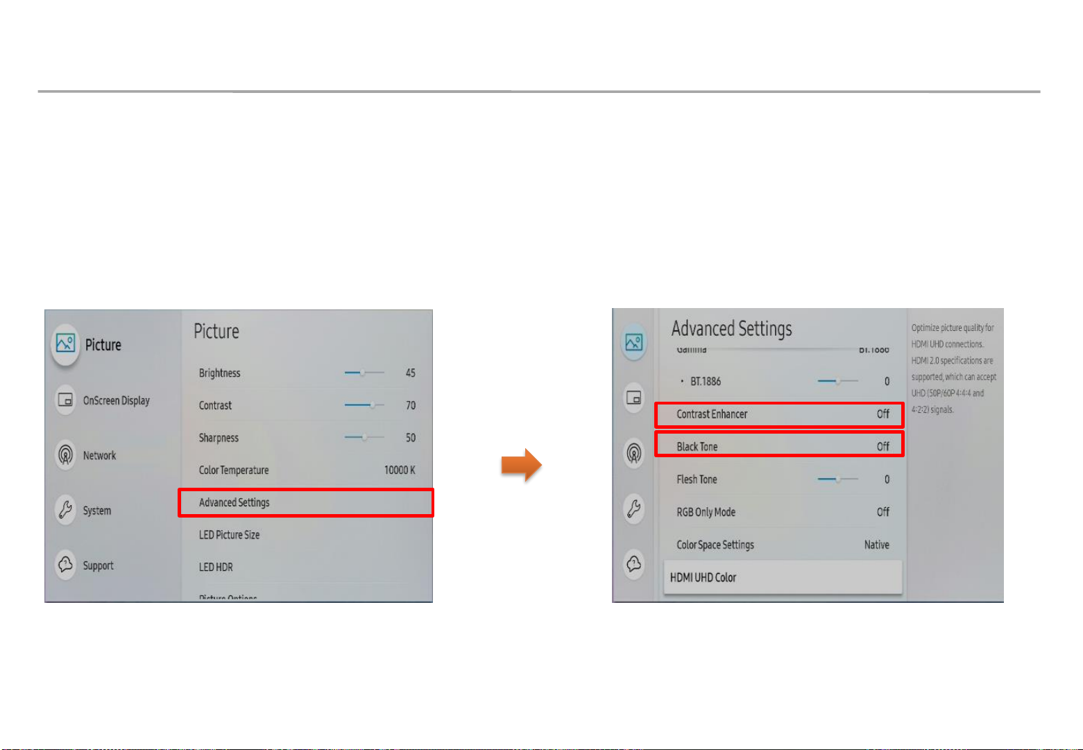
⑤ Picture settings
To use S-Box Grouping, make sure both the Dynamic Contrast and Black Tone functions are off so as to
minimize a picture quality difference between S-Boxes.
Menu→ Picture → Advanced Settings,
- Dynamic Contrast: default “Medium” → Off
- Black Tone: default “Darker” → Off
Page 50
Samsung Electronics
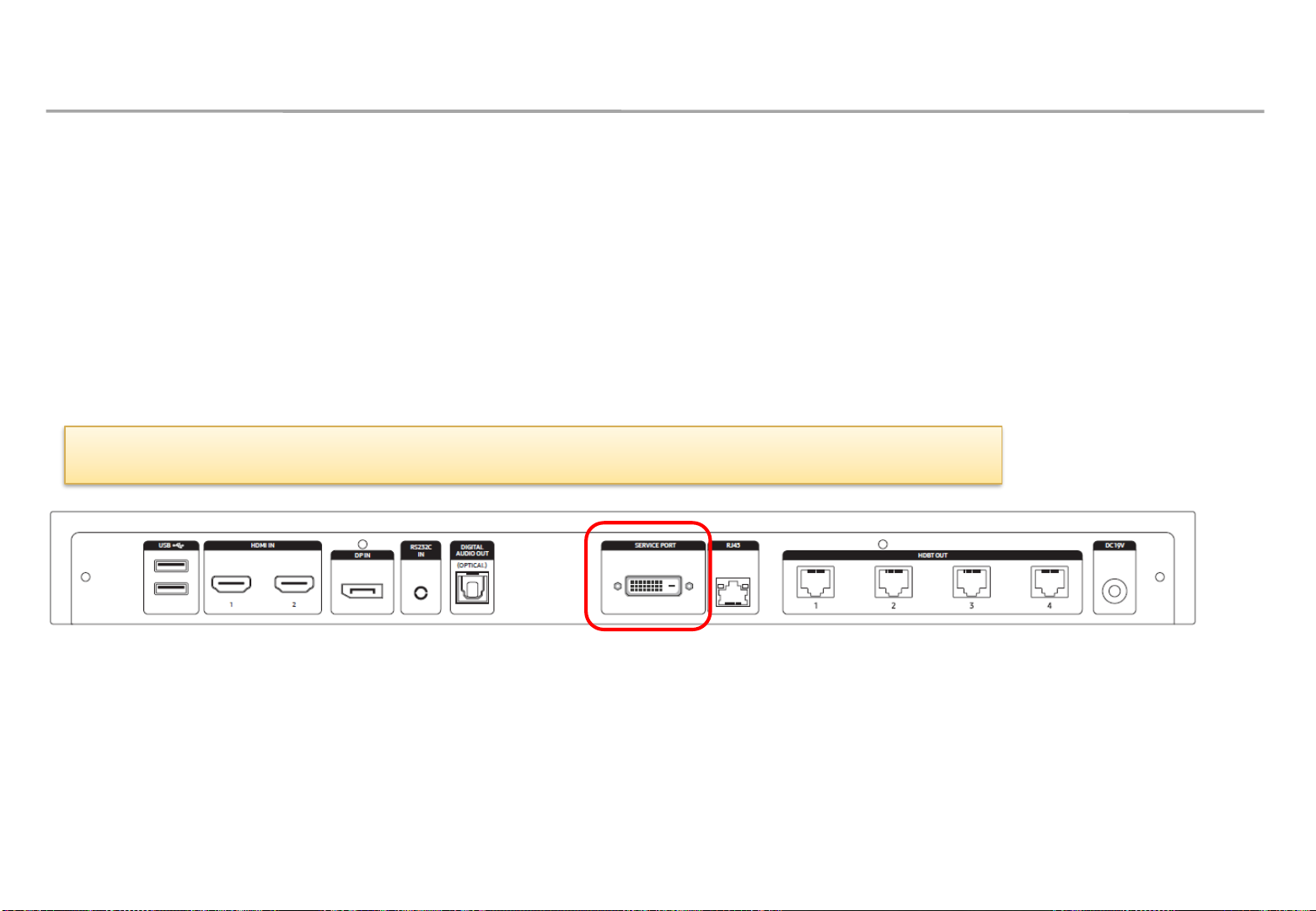
① The Service port is a dedicated monitoring port used to access the OSD menu during initial installation of an S-Box and
check the playback status of a source device.
② The resolution for the Service port is FHD (1920*1080 @ 60 Hz).
③ If a source device with a UHD resolution is connected to an S-Box, screen flickering may occur or a corrupted screen
may be displayed. This issue is caused due to 2:1 downscaling of the Service port with no specific scaling algorithm and
has nothing to do with the actual LED cabinet screen display.
[Caution!] This port is for service use only and has no function for the user. Do not connect any cable
to this port.
5. S-Box Installation and Connection
• S-BOX Connection (Service Port)
Page 51
Samsung Electronics
50
5. S-Box Installation and Connection
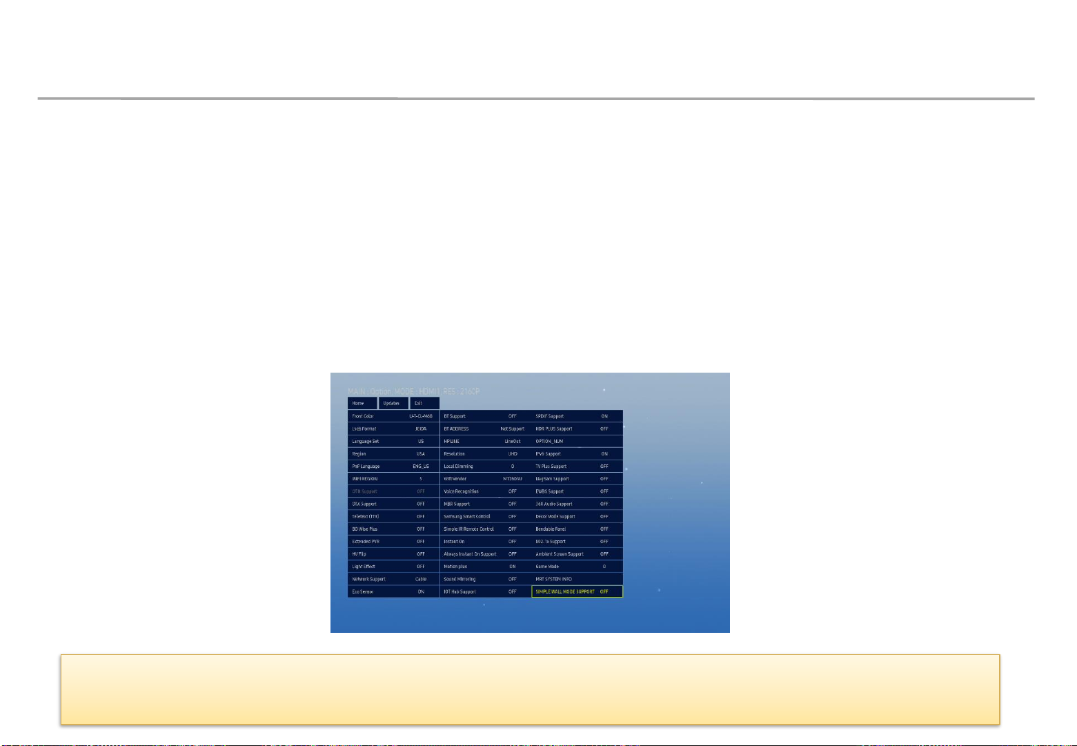
① Follow the steps below to access the Factory Menu.
- Connect the external IR cable to the S-Box.
- Press the power off button on the remote control Wait for 10 seconds Press Mute - 1 - 8 - 2
Click the “Power on” button
② In the Factory Menu, select Option MRT option SIMPLE WALL MODE SUPPORT ON
[Caution!] Do not run Simple wall mode if multiple S-Boxes are connected.
The S-Boxes may not display wallpaper simultaneously.
• Simple wall mode
This mode is used to easily display a wallpaper when you do not want the product to display a blank
screen while not in use.
If the screen resolution is smaller than the S-Box output resolution, use the Factory Menu to turn on the
Simple wall mode.
Page 52
Samsung Electronics
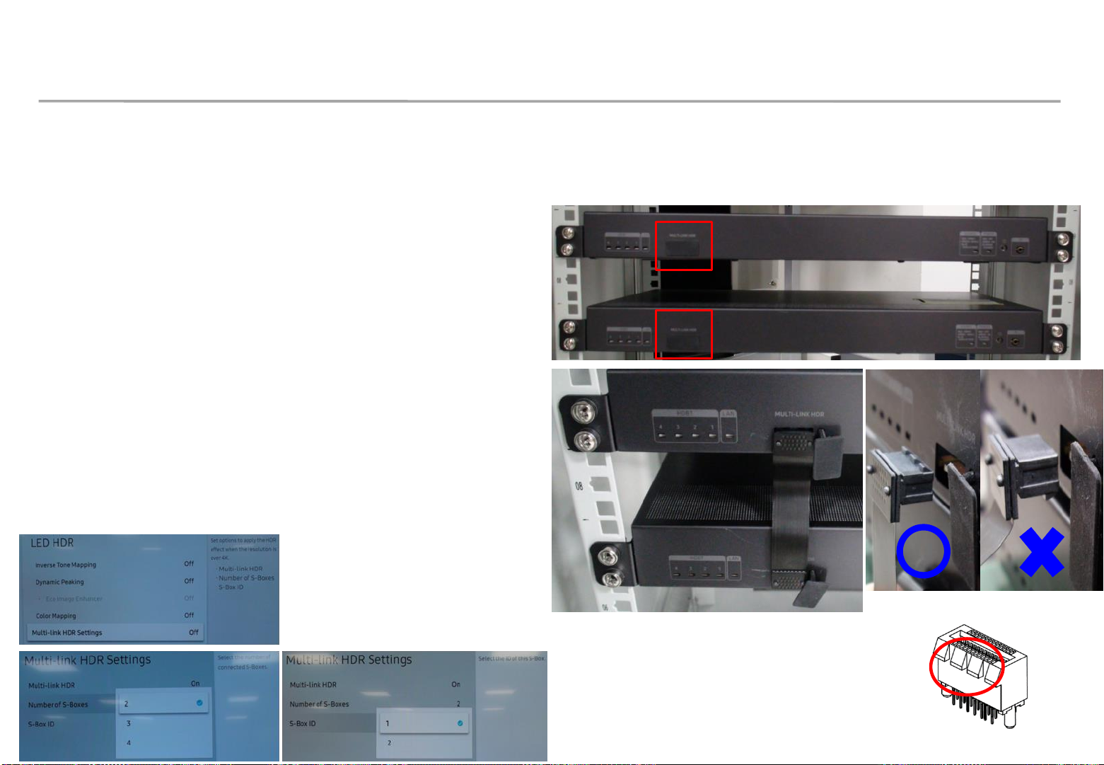
Product recommend installing this product in a standard 19-inch server rack,
please refer 25 page about basic installation guide.
51
5. S-BOX Installation and Connection(Only SBB-SNOWJMU model)
• How to install when use Multi Link HDR function
Multi Link HDR Port
Multi Link HDR Port
① Please open rubber plug of Multi Link HDR port.
② Connect the connector of the cable of Multi Link HDR to
the Multi Link HDR port of each S-BOX.
(Refer 87page about Cable)
(※ Note : Connect the connector’s structure to face up)
③ Menu – Picture – LED HDR – Multi Link HDR Settings –
ON
④ Set the quantity of S-BOX connected each other. (2/3/4)
⑤ Set S-BOX ID
(※ Note: It is necessary to set the ID not to overlap
between connected S-BOX)
UP
SIDE
Page 53
Samsung Electronics
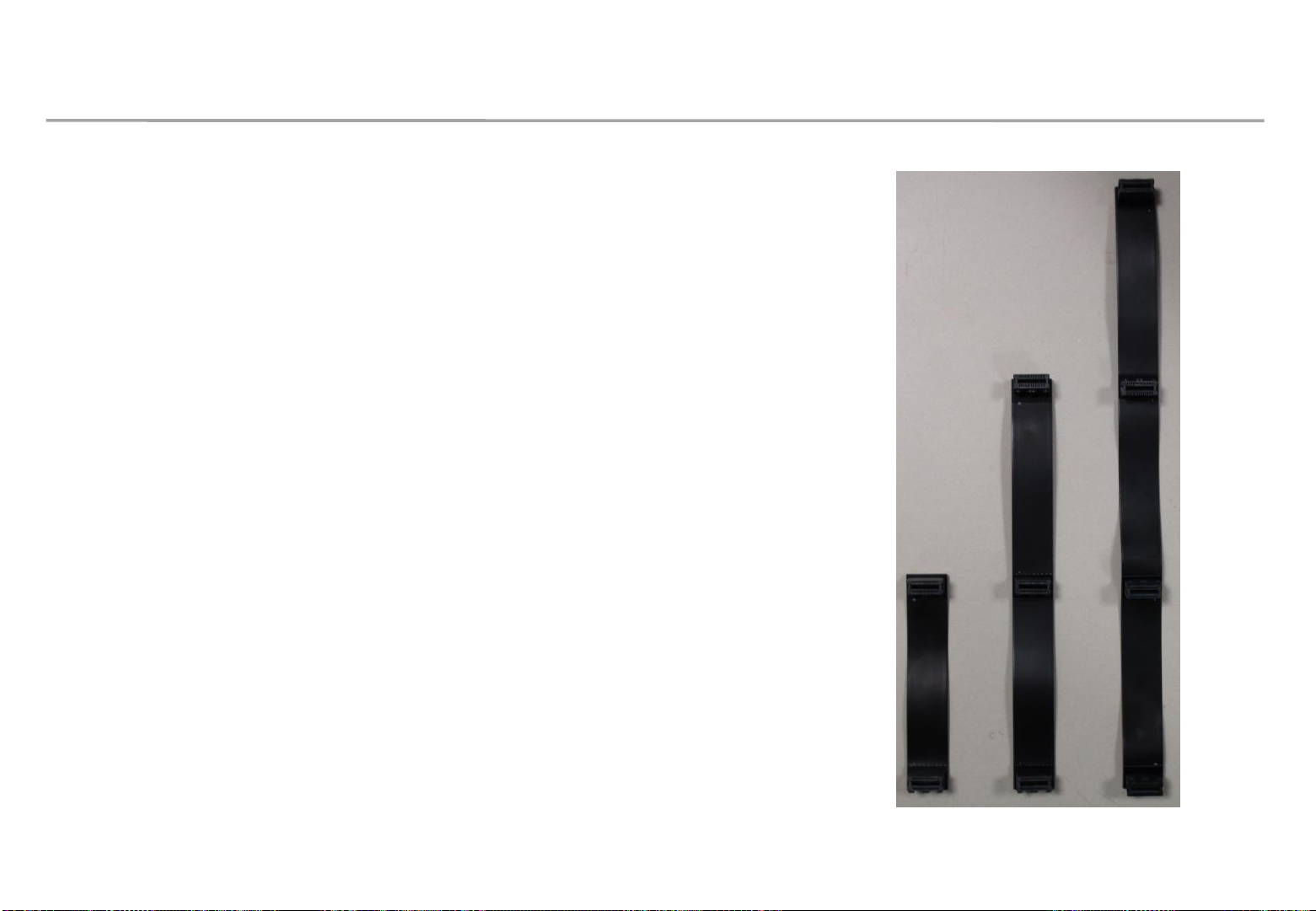
Use the appropriate cable according to the quantity of S-BOX connected.
52
5. S-BOX Installation and Connection(Only SBB-SNOWJMU model)
• Multi Link HDR Cable
Multi Link HDR Port
Multi Link HDR Port
Page 54
Samsung Electronics
※ Note : Before update, disconnect the Multi Link HDR Cable from S-BOX.
53
5. S-BOX Installation and Connection(Only SBB-SNOWJMU model)
• FPGA Update Guide when using Multi Link HDR Cable
Multi Link HDR Port
Factory update method
① Save a SW program called ‘TB-XCKUSBMWWS.bin’ in USB root.
② Connect the USB to S-BOX.
③ Enter Factory mode.
(Remote control ‘mute +1+8+2+Power ON’ in power off state)
④ Select “SVC → UPGRADE” menu.
⑤ Move the cursor to “FPGA UPGRADE” menu.
⑥ Press ‘Enter’ in the remote control.
⑦ Press ‘▶’ button in remote control to start the upgrade.
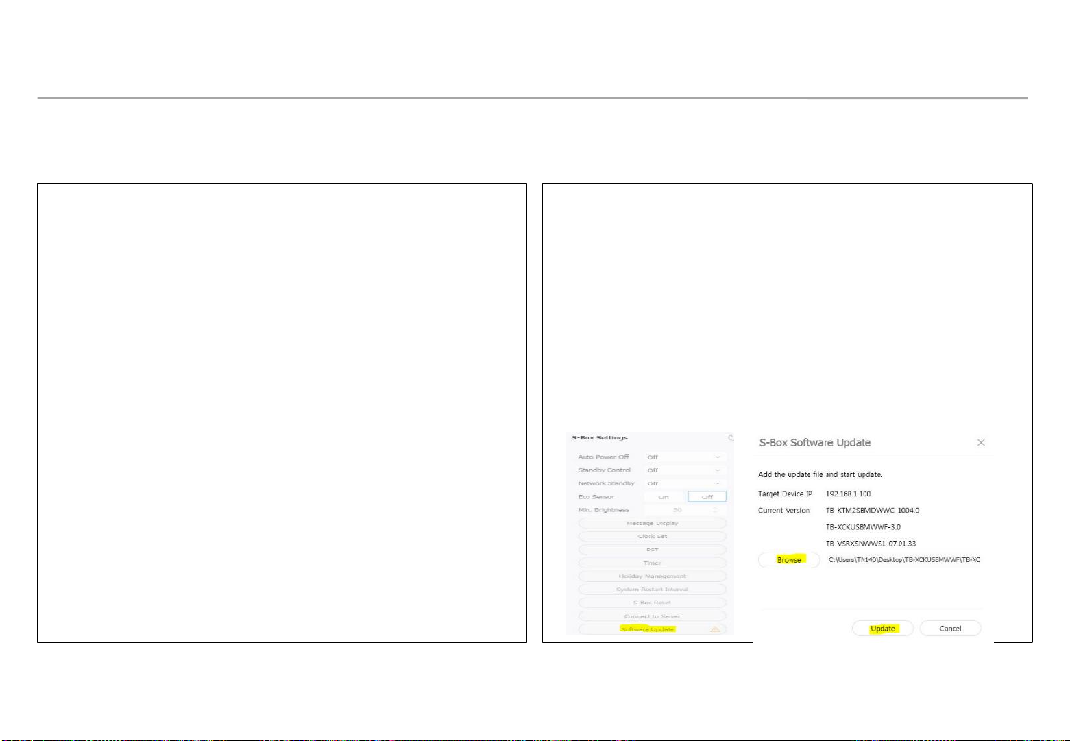
LSM update method
① Select ‘S-BOX Settings – Software Update’ in LSM menu.
② Select ‘Broswer’ and move to the folder with the FPGA update file
(TB-XCKUSBMWWF.bin + Info.txt)
※ Version in ‘Info.txt’ file should be higher than currently installed
version
③ Select ‘TB-XCKUSBMWWF.bin’ file.
④ Select ‘Update’ button to start the upgrade.
※ Note : In case of the sites that are difficult to remove the Multi Link HDR cable, all connected S-BOX
should be AC power off/on after LSM update done. (Must turn off AC power after the update
of all S-BOX are completed)
Check the version of FPGA after update.
Page 55
Samsung Electronics
9-1. PC-specific control software
6. Settings / How to Use
54
LSM (LED Signage Manager)
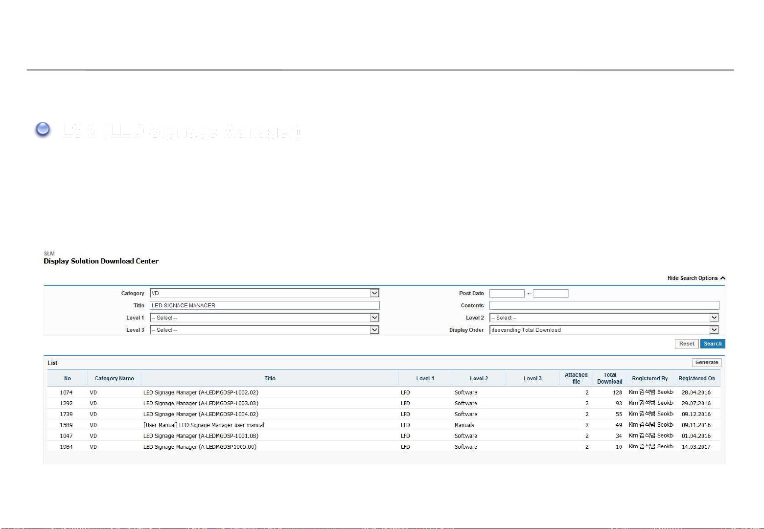
• How to download LSM: Access GSBN, select SLM - Display solution download, and then select
"LED SIGNAGE MANAGER" or "LSM“
- GSBN: http://v3.samsunggsbn.com/ep
Page 56
Samsung Electronics
6. Settings / How to Use
55
9-1. PC-specific control software
Network IP Setting Tool
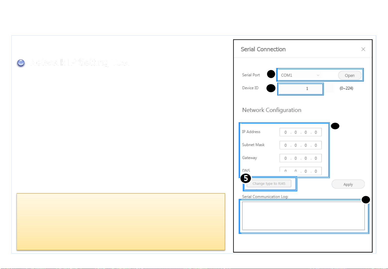
Use the File Explorer to go to the folder where LSM is installed.
Select [Start] – Programs – Samsung – LED Signage Manager – Network
Configuration.
1. Use the RS232C cable to connect the PC to the S-Box. Select the
connected Serial port and press the Open button to establish a
connection.
2. The ID of an S-Box is set to “1” by default.
3. Enter the IP address, subnet mask, gateway and DNS for the S-Box, and
press the Apply button to send the data.
4. View the result. View the MDC Protocol setting status.
5. The “Change Type to RJ45” button is displayed if IP settings have been
configured correctly. Connect the LSM to the S-Box. If the product
works properly, press the “Change Type to RJ45” button to switch the
S-Box connection mode to “RJ45.”
3
1
2
4
[★ Caution!] When configuring S-Box network settings, it is recommended
that a static IP address be used.
If DHCP is used and the IP address is changed, the connection with LSM may
be disconnected.
The 192.168.10.x band is used for internal communication with LED cabinets.
Use an IP address that does not belong to this band.
Use the IP address for S-Box (x1) assigned by your IT administrator. Do not
allocate an IP address arbitrarily.
Page 57
Samsung Electronics
9-1. PC-specific control software
6. Settings / How to Use
56
• Software for remote control of LED cabinet layout
LSM (LED Signage Manager)
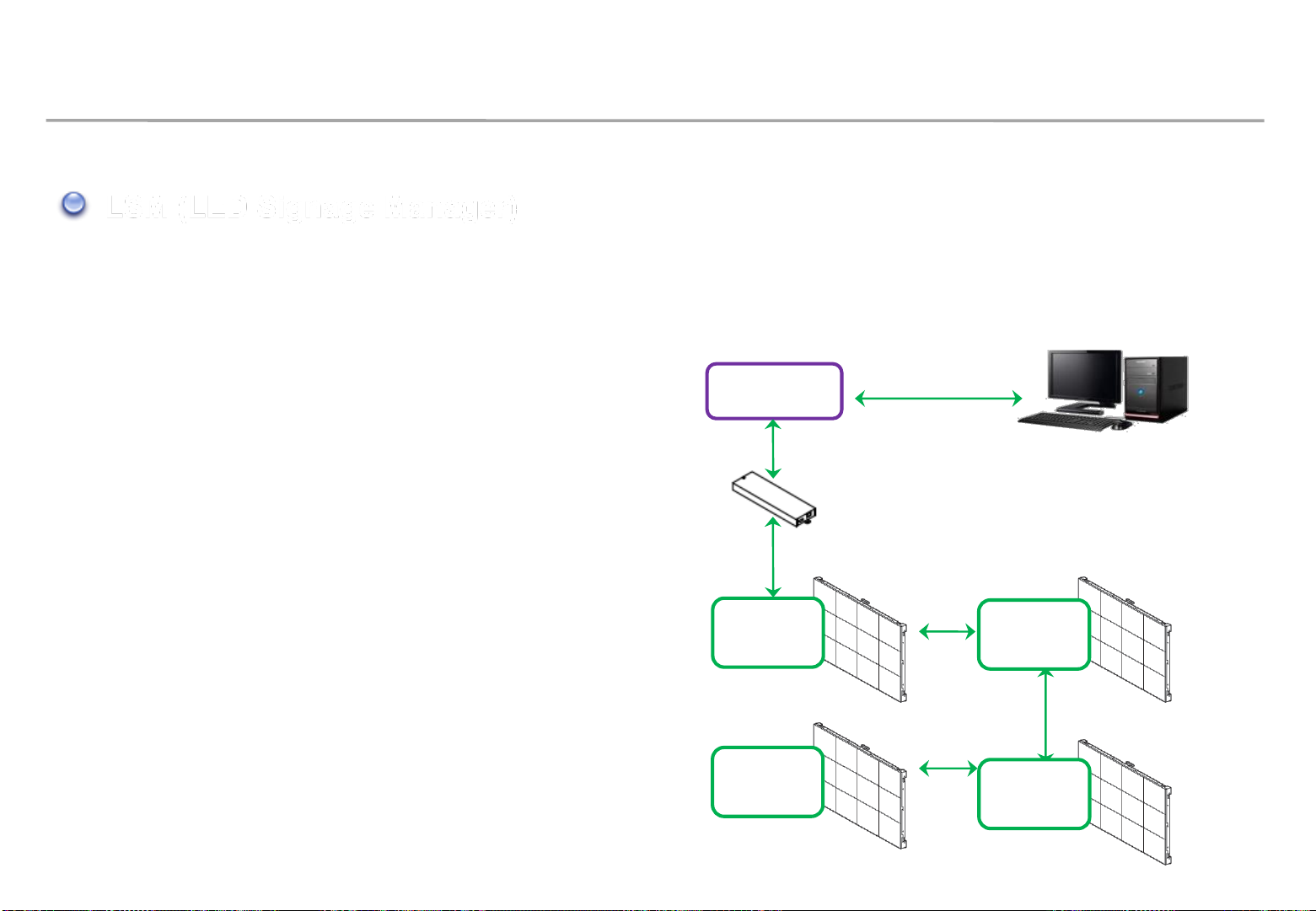
Control PC
S-Box
Cabinet 1
Ethernet
Interface Gender
Vx1
Vx1
Vx1
HDBT
Vx1+Ethernet
Cabinet 2
Cabinet 3
Cabinet 4
1. Connect the PC to the S-Box via Ethernet.
2. Use a LAN cable to connect the S-Box to the Interface Gender.
3. Use an OCM cable to connect the Interface Gender to the first LED
cabinet.
4. Use OCM cables to connect the LED cabinets to one another in a
daisy-chain configuration.
Page 58
Samsung Electronics
9-1. PC-specific control software
6. Settings / How to Use
57
• Start– Login Page
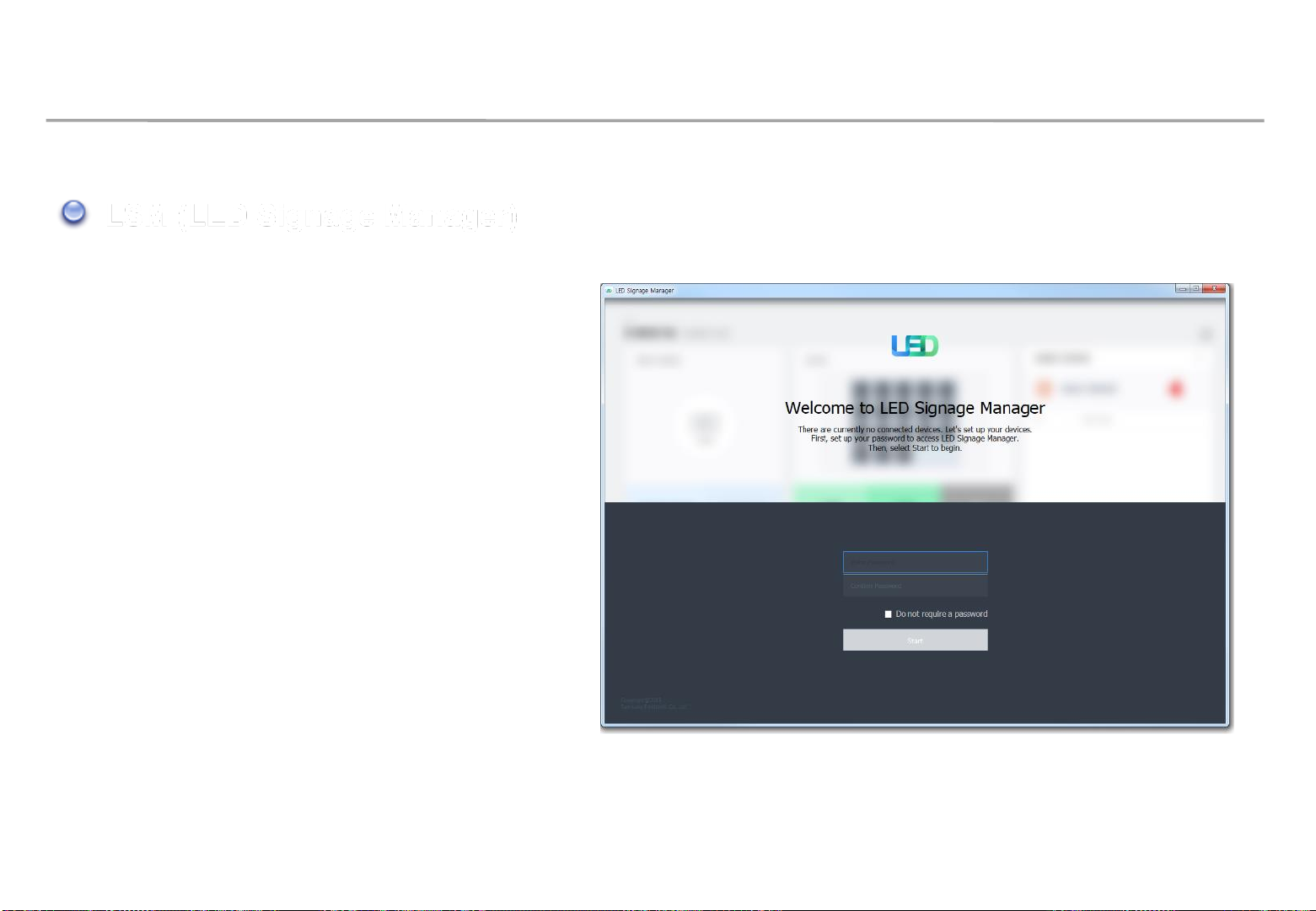
1. When the LSM is launched for the first time, the
password setting page appears.
2. To set a password, enter the same password of
your choice twice and click the Start button.
3. If you do not want to use a password, select the
“Don’t use password” checkbox.
If this checkbox is selected, you not prompted for
a password when the LSM is launched
subsequently.
LSM (LED Signage Manager)
Page 59
Samsung Electronics
9-1. PC-specific control software
6. Settings / How to Use
58
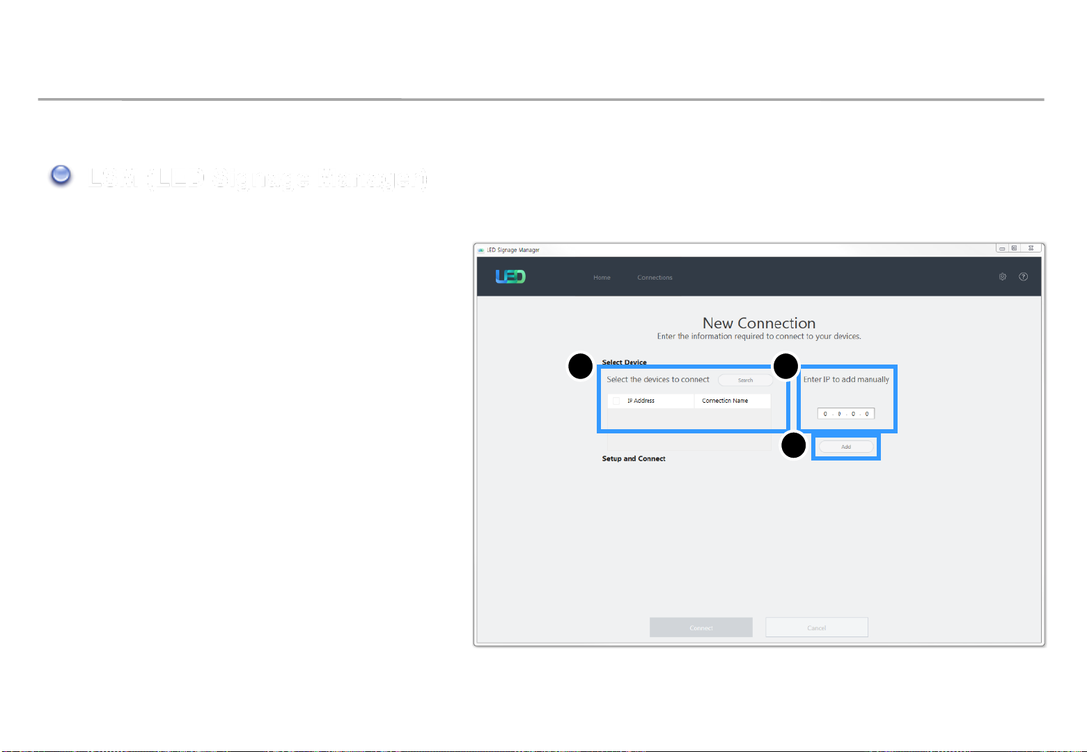
• New Connection
1. To add connection information, use the Search button
to search for an IP address or manually enter an IP
address. If you click the Search button, the IP address
for LSBs available for connection on the same network
appear. Alternatively, manually enter the IP address if
you know the IP address for the target LSB for
connection.
2. Click the Add button. Entered connection information
is added to the Setup and Connect settings.
3. The user can select an S-Box model type. Three model
types are available for selection:
Without Cabinet IP / With Cabinet IP(FHD) / With
Cabinet IP(UHD).
LSM (LED Signage Manager)
1 1
2
Page 60
Samsung Electronics
9-1. PC-specific control software
6. Settings / How to Use
59
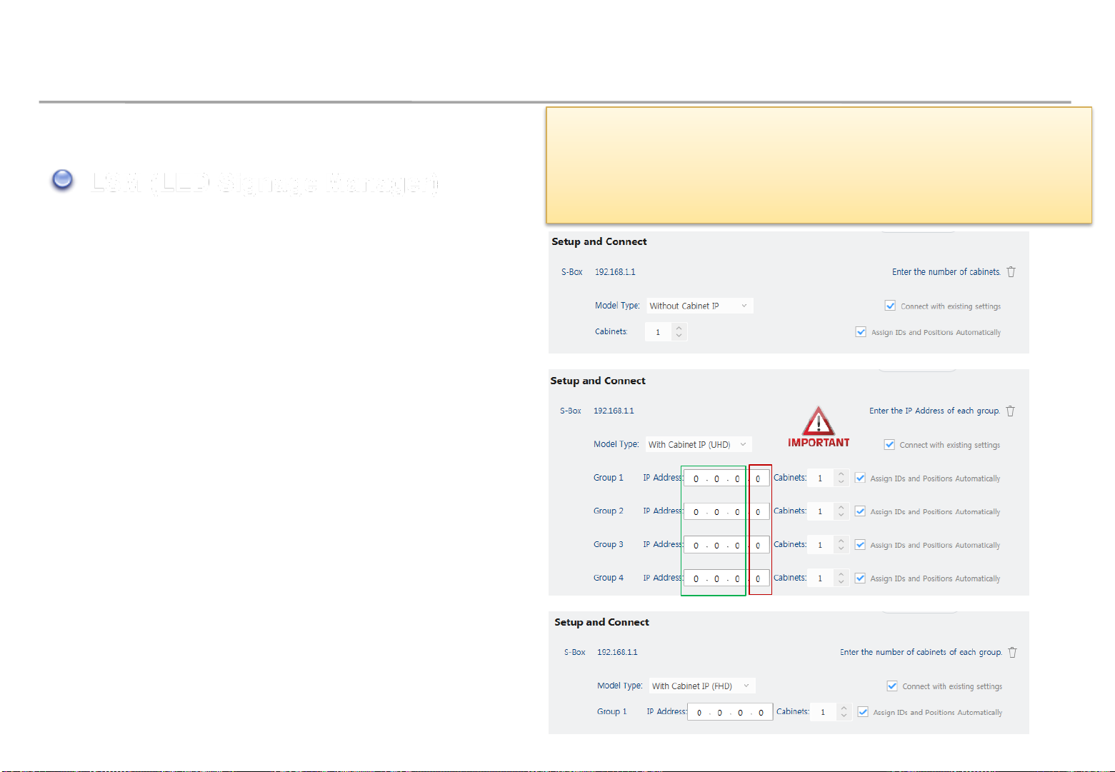
• New Connection-Connect
1. If using an old version LSB, select “Without Cabinet IP.”
2. If using a UHD LSB, select “With Cabinet IP (UHD).” Make
sure assigning a different IP address for each port
connected LED cabinets. Set the number of connected
cabinets and click “Connect.”
3. If using an FHD LSB, select “With Cabinet IP (FHD).” Set
the IP addresses for the LED cabinets, and the number of
connected cabinets, and then click “Connect.”
※ If IP addresses are already set for the cabinets, select the “Connect
with existing settings” checkbox.
※ If using UHD and some of the four ports will only be used, only
enter the IP addresses for the corresponding groups.
LSM (LED Signage Manager)
※ Should be the same
as S-Box
※ Should be different than S-Box / Should be different for each group
[★ Caution!] When configuring LED cabinet network settings, it is recommended that
a static IP address be used.
If DHCP is used and the IP address is changed, the connection with LSM may be
disconnected.
The 192.168.10.x band is used for internal communication with LED cabinets.
Use an IP address that does not belong to this band.
Use the IP address for LED (x4) assigned by your IT administrator. Do not assign an
IP address arbitrarily.
Page 61
Samsung Electronics
9-1. PC-specific control software
6. Settings / How to Use
60
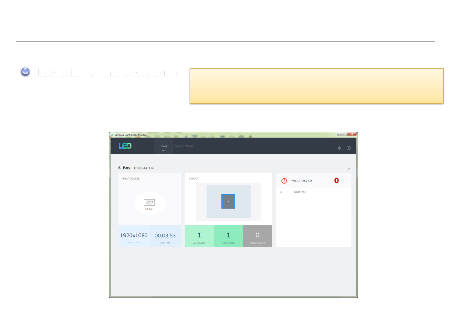
• Main Window-Home Window
1. Home screen: Shows information about connected devices, the input source, the cabinet configuration, and devices with errors.
LSM (LED Signage Manager)
[★ Caution!] For internal communication between the S-Box and LED cabinets,
use ports 1515 and 48485.
When firewalls / security network are in use, make sure the corresponding port
between the S-Box and LED cabinets is enabled.
Page 62
Samsung Electronics
9-1. PC-specific control software
6. Settings / How to Use
61
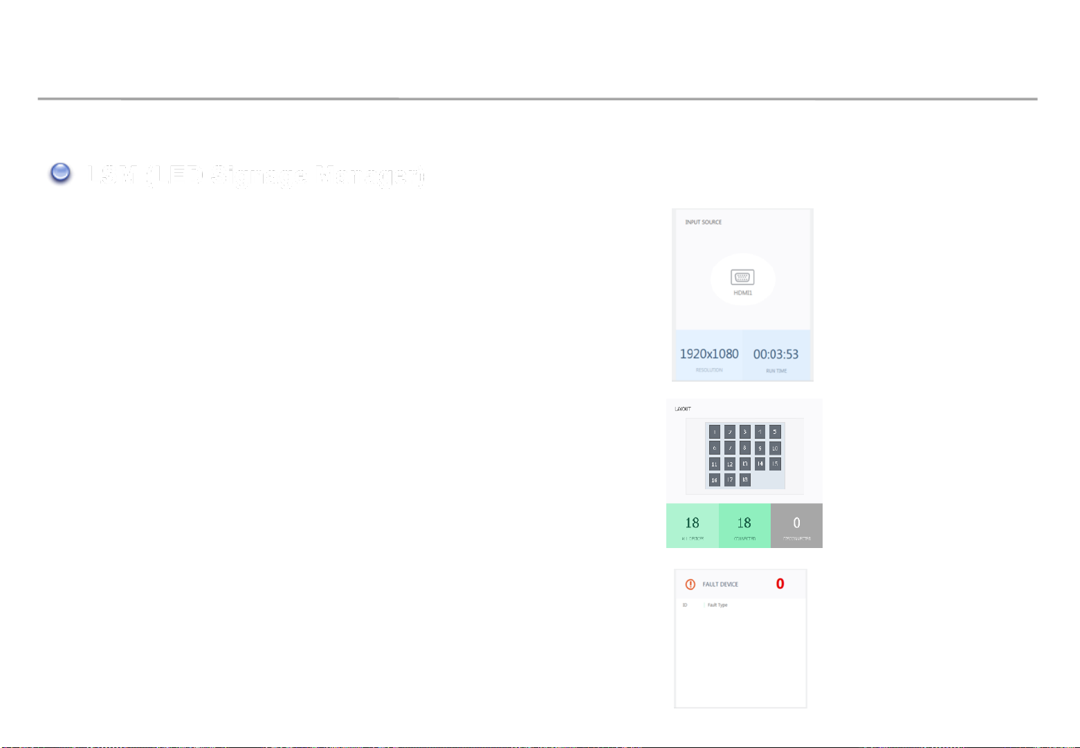
1. INPUT SOURCE: Shows the LSB input source, resolution
and connection duration.
2. LAYOUT: Shows the layout and quantity of all LED cabinets
and the quantities of connected and disconnected cabinets.
3. FAULT DEVICE: Shows the IDs of faulty LED cabinets and
the fault details.
• Main Window-Home Window
LSM (LED Signage Manager)
Page 63
Samsung Electronics
9-1. PC-specific control software
6. Settings / How to Use
62
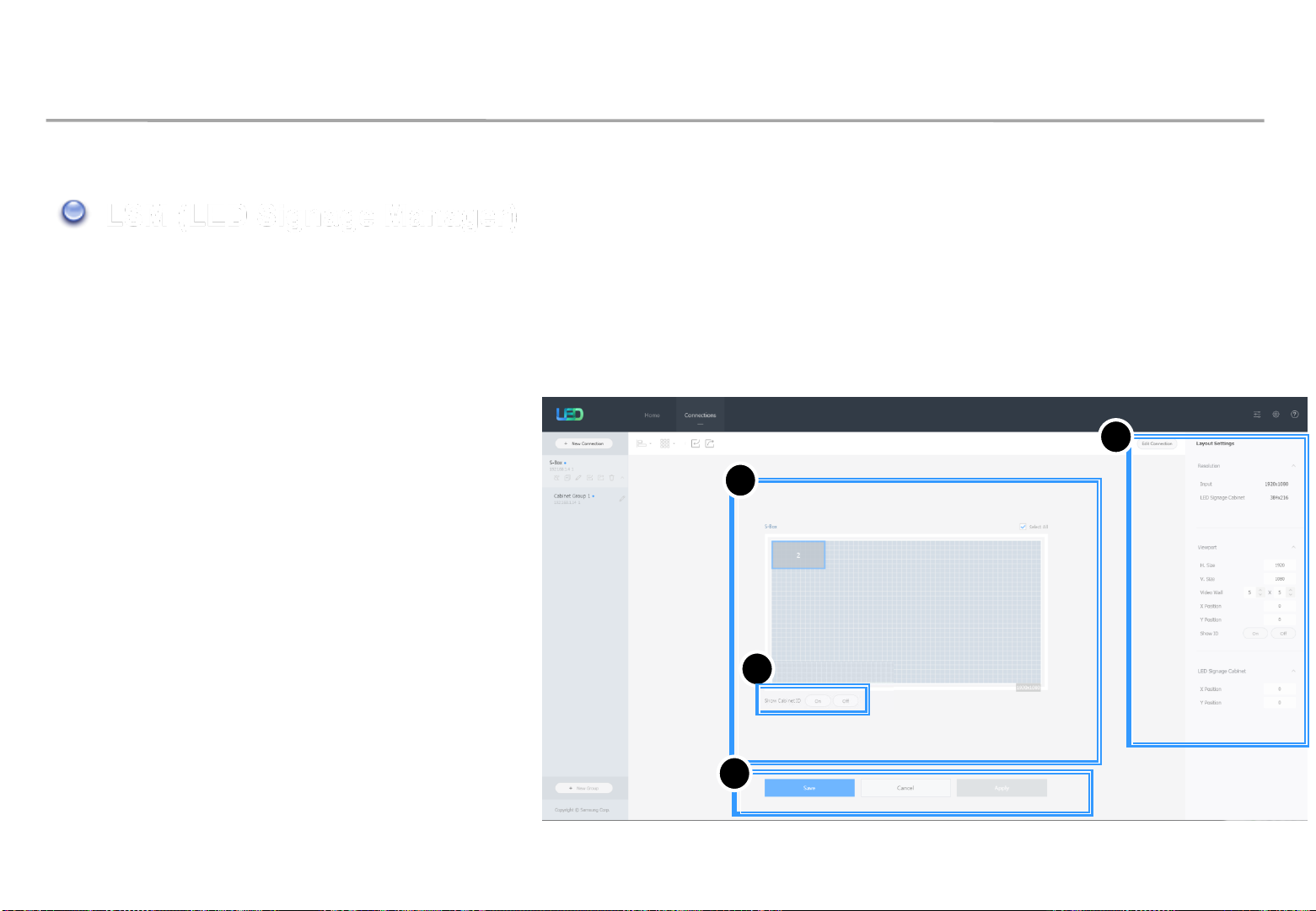
• Main Window-Edit Connection Layout Window
1. Connection layout: Use the LSB output source
section to adjust the LED cabinet layout by
rearranging cabinets.
2. Feature View: Provides the Edit button used to edit
connection information and the automatic LED
cabinet alignment function.
3. Device Information/Setting View:
Shows LED cabinet information based on the
following categories.
(i) Resolution: Resolution of the input source
(ii) ViewPort: Width/height, video wall matrix, x/y
coordinate settings
(iii) LED Signage Cabinet: X, Y positions of LED
cabinets
4. Show ID: Select to cause each of all connected LED
cabinets to display their ID.
5. Save/apply or cancel settings
LSM (LED Signage Manager)
1
2
4
3
Page 64
Samsung Electronics
9-1. PC-specific control software
6. Settings / How to Use
63
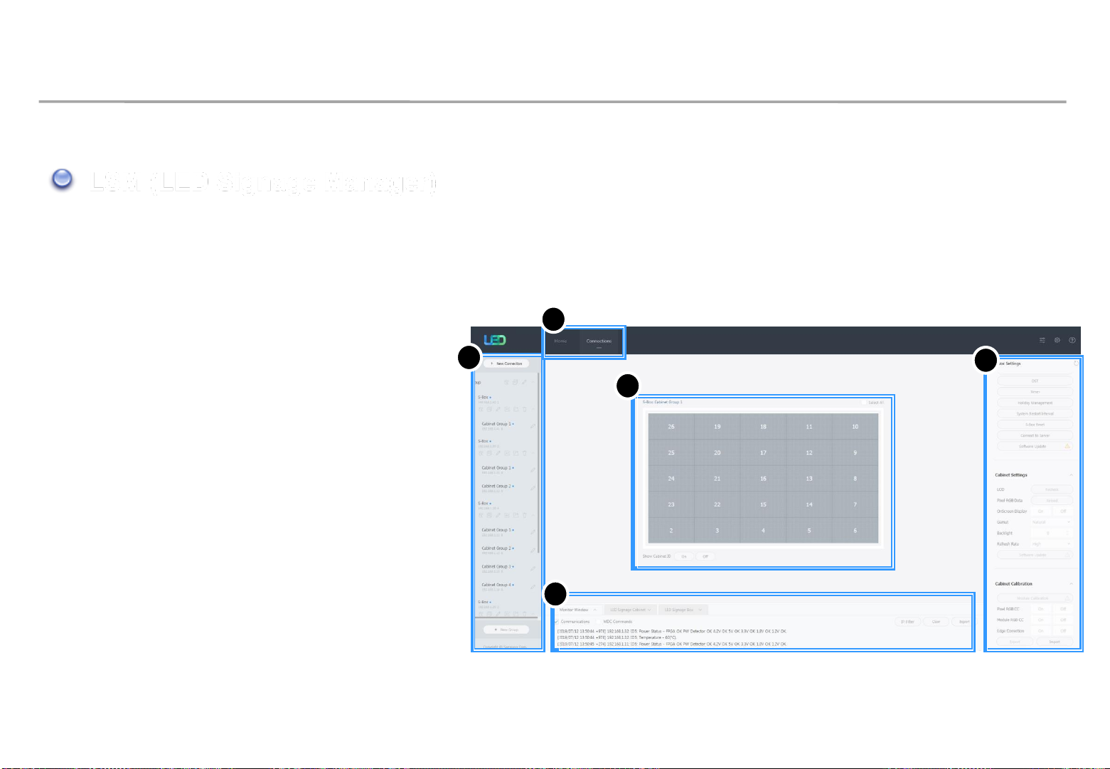
• Main Window-Connection Window
1. Device connection list view:
View LSB configuration information. Edit or
delete LSB connections. View LED cabinets
by group.
2. Connection layout (View Port):
View the LED cabinet layout and the position
of each LED cabinet
3. Category View:
Use the Home and Connections tabs to
configure system settings.
4. Device Information/Setting View:
Change LSB settings (e.g. screen settings).
5. Sub Information View: Displays
monitoring logs, and LSB and LED cabinet
information.
LSM (LED Signage Manager)
1
2
4
5
3
Page 65
Samsung Electronics
9-1. PC-specific control software
6. Settings / How to Use
64
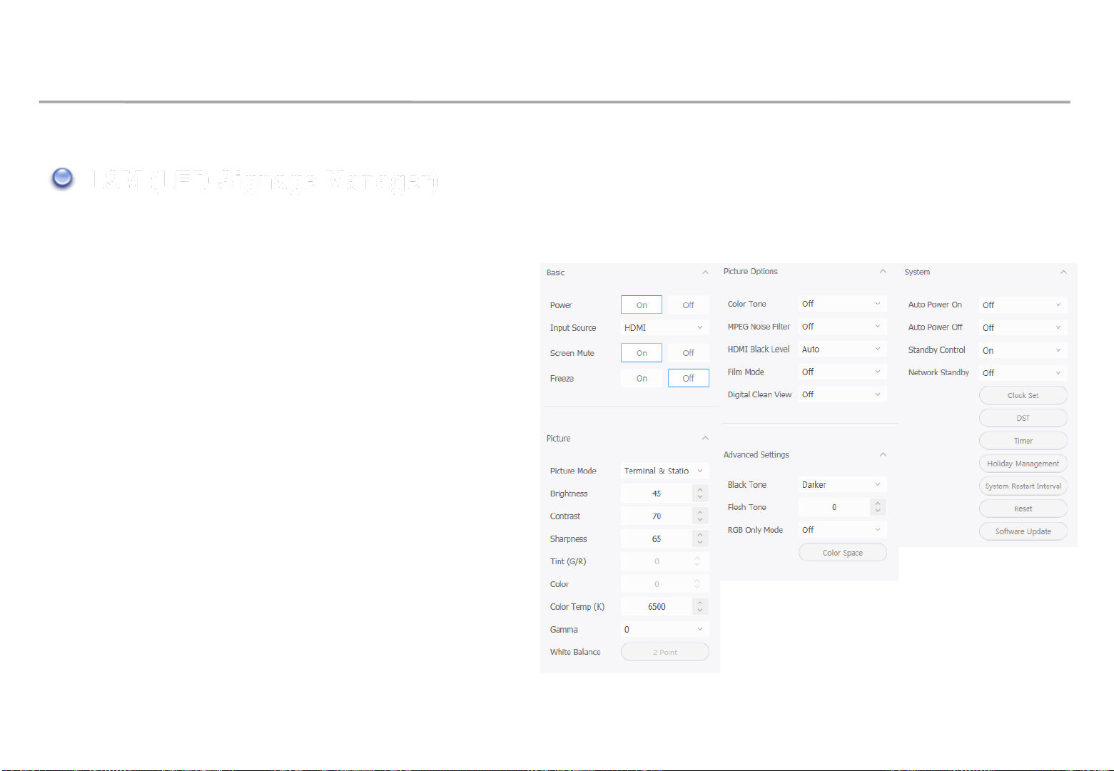
• Main Window-Connection Window - Device Information/Setting View
LSM (LED Signage Manager)
1. Basic :
. Turn on/off the S-Box. Change the input
source. Mute or free the screen.
2. Picture
. Change the screen mode. Adjust brightness,
contrast, sharpness, color, tint (G/R), color
temperature (K), gamma or white balance.
3. Picture Options
. Adjust color tone, HDMI black level, film
mode and other settings.
4. Advanced Settings
. Adjust black tone, facial color tone, color
space and other settings.
5. System
. Turn on/off Auto Power On or Off. Turn on/off
Standby Control. Set the clock, timer and/or
system restart interval. Use the software
update function.
Page 66
Samsung Electronics
9-1. PC-specific control software
6. Settings / How to Use
65
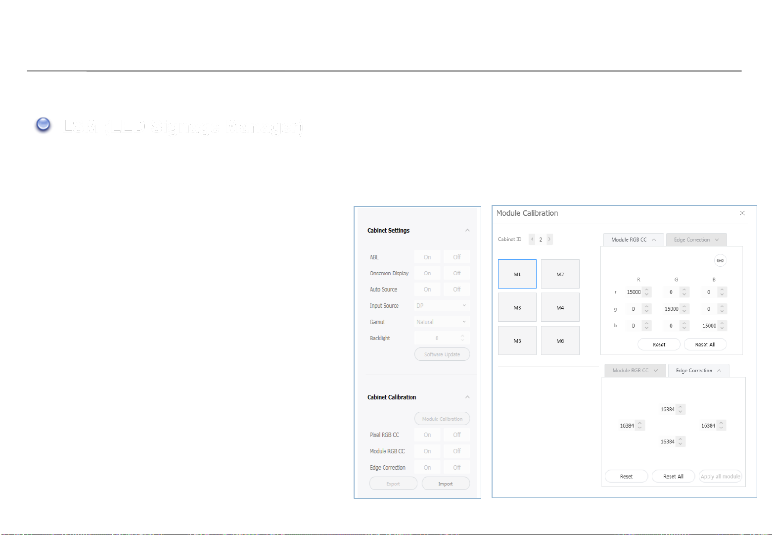
• Main Window-Connection Window - Device Information/Setting View
LSM (LED Signage Manager)
6. Cabinet Settings
. Turn on/off ABL, and set Gamut and Backlight.
. Use the software update function (e.g. FPGA,
module calibration data).
6. Cabinet Calibration
. Perform RGB CC calibration for each module.
. Calibrate the boundary surface of each module.
. Turn on/off CC. Turn on/off Edge Correction.
. Download module calibration data through
Batch Upload/Import/Export.
Page 67
Samsung Electronics
9-1. PC-specific control software
6. Settings / How to Use
66
• Main Window-Connection Window - Sub Information View
LSM (LED Signage Manager)
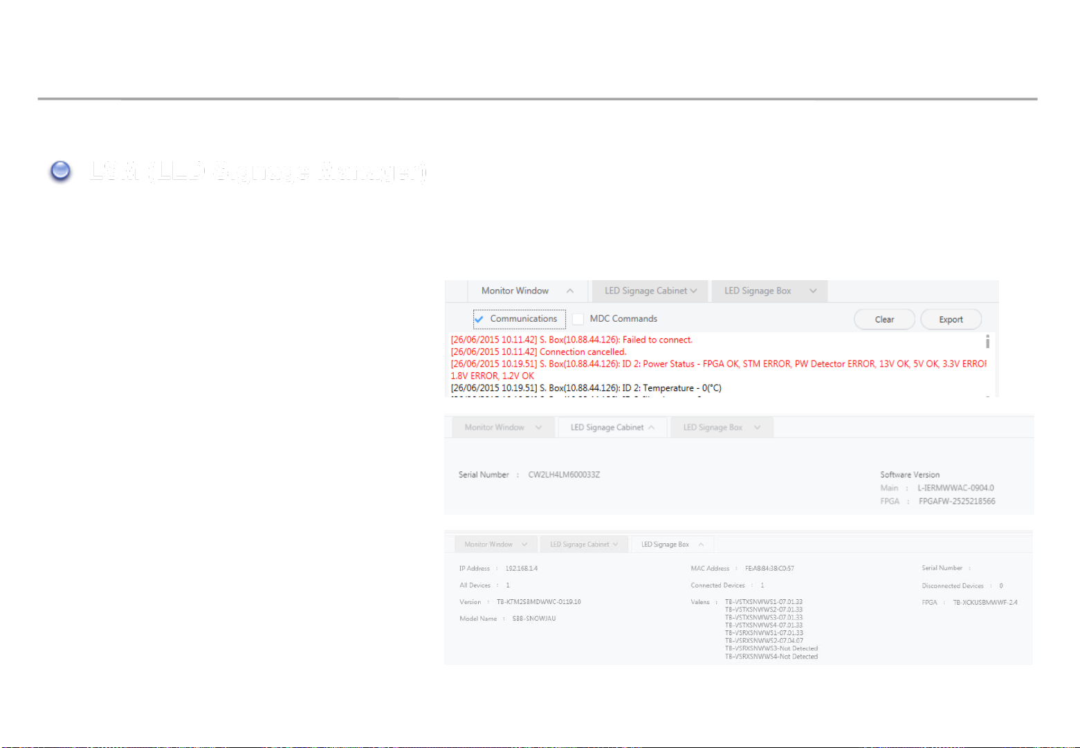
1. Monitor Window:
View MDC communication logs and
information about connected devices.
Extract data by using files.
2. LED Signage Cabinet: Shows chip information
and cabinet power information.
3. LED Signage Box:
Shows the IP address, MAC address, LED
cabinet ID range, numbers of all, connected
and disconnected, serial number, and version
information.
Page 68
Samsung Electronics
9-1. PC-specific control software
6. Settings / How to Use
67
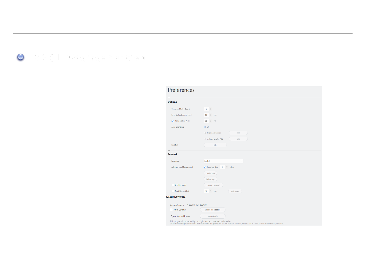
• Main Window - Preference
1. Options
Set the command retry count.
Set the error status checking interval.
Set the temperature alert threshold.
2. Support
Select a language.
Configure log data management settings.
3. Set the interval to email a device error alert.
Change the password.
4. About Software
Shows the LSM version and provides the
update function.
LSM (LED Signage Manager)
Page 69
Samsung Electronics
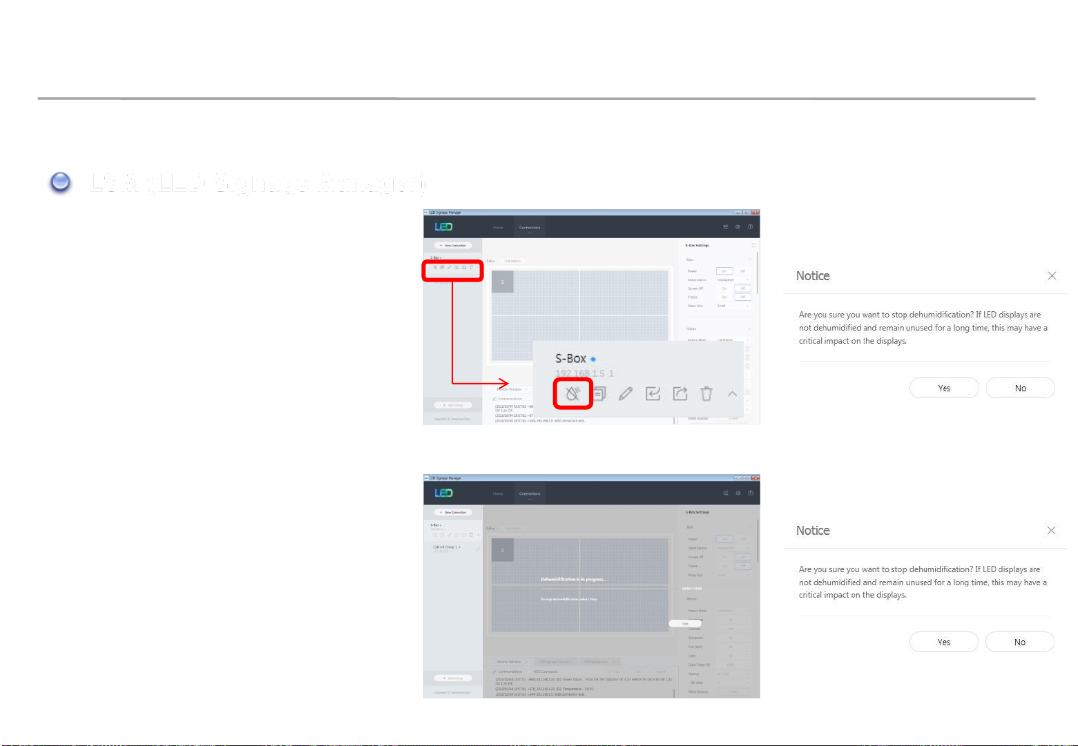
• Dehumidification Mode using LSM
1. The dehumidification mode icon is provided
under the S-Box menu.
2. To turn on dehumidification mode, click the
icon.
3. It is possible to view how long the
dehumidification has been on.
4. To turn off the mode, click the “Stop” button.
9-1. PC-specific control software
6. Settings / How to Use
LSM (LED Signage Manager)
68
Page 70
Samsung Electronics
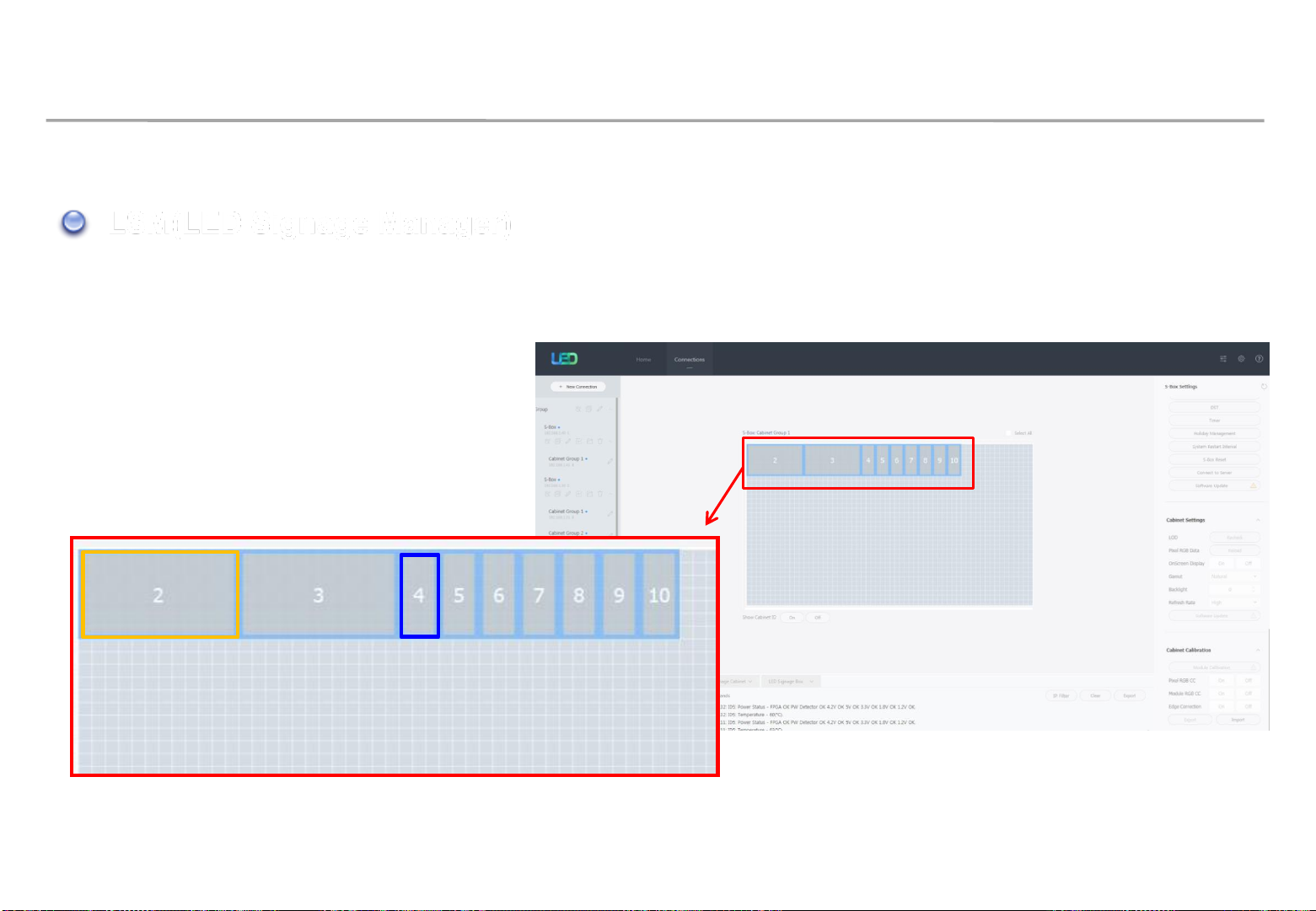
• Mixed use for IER and IER-F
7. Control Program for PC
7. Settings / How to Use
69
※ IER and IER-F can be connected to the same port.
- There is no connection order for IER and IER-F.
- Combination is possible within an FHD screen
(the same I/G port).
- Use the same firmware for both IER and IER-F.
LSM(LED Signage Manager)
IER
IER-F
Page 71
Samsung Electronics
8-1. Cable connection (IER Series)
8. Power and Cable Connection
70
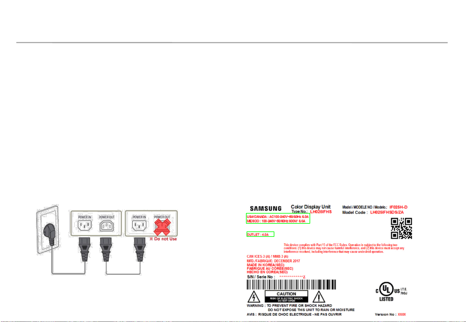
• If using 110V power, IER P2.0 / P2.5 / P4.0 allows power connection to a maximum of 3 / 4 / 4 cabinets.
For IER-F, 10 cabinets (each pitch)
• If using 220V power, IER P2.0 / P2.5 / P4.0 allows power connection to a maximum of 6 / 7 / 7 cabinets.
For IER-F, 20 cabinets (each pitch)
• In case of powering IER and IER-F together, adjust cabinet number so that total Power consumption is under 1000W
• Make sure the quantity of connected cabinets does not exceed the recommended quantity. If the recommended quantity is
exceeded, the breaker may trip or the product may become damaged due to over-current.
※ Samsung Electronics is not responsible for problems caused as a result of exceeding the recommended quantity of
connections.
• The rated voltage for the product and the rated current for the outlet can be found in the label attached on the rear of the product.
• Transfer power by daisy chain with extension power cable
• Do not use Power out socket of last Cabinet
Page 72
Samsung Electronics
8-1. Cable connection (IFR Series)
8. Power and Cable Connection
71
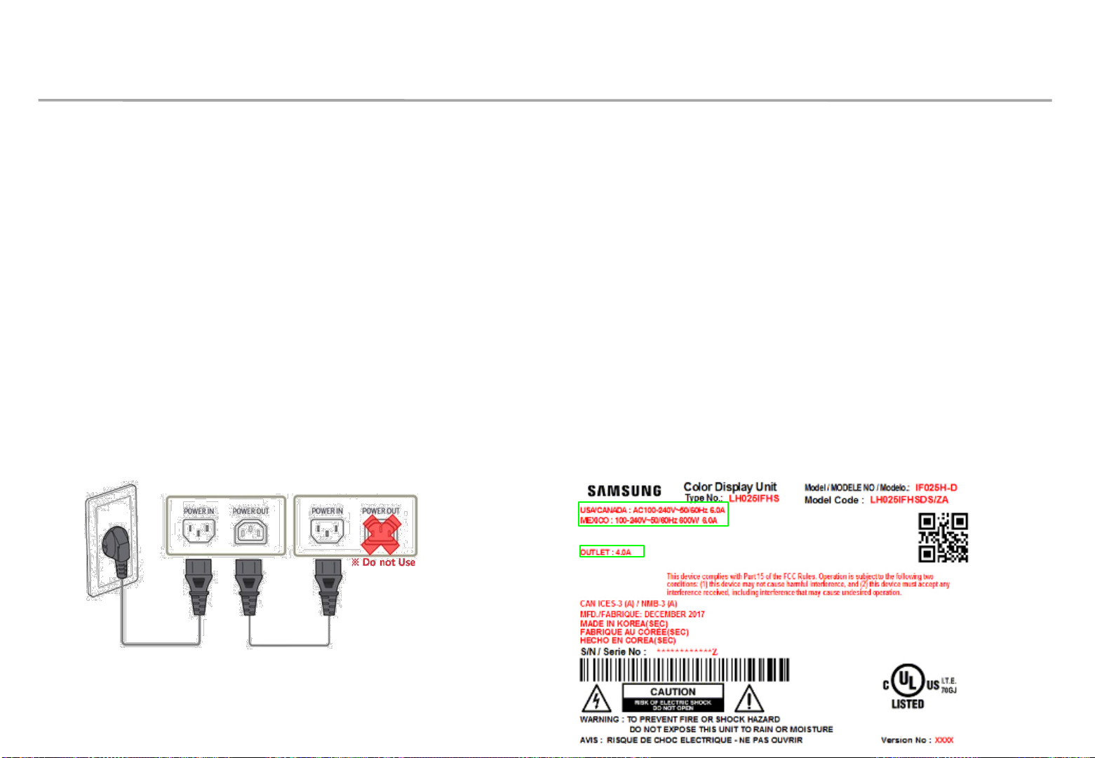
• If using 110V power, IFR P2.5 / P4.0 allows power connection to a maximum of 2 / 2 cabinets. For IFR-F, 7 cabinets (each pitch)
• If using 220V power, IFR P2.5 / P4.0 allows power connection to a maximum of 4 / 4 cabinets. For IFR-F, 20 cabinets (each pitch)
• In case of powering IFR and IFR-F together, adjust cabinet number so that total Power consumption is under 1000W
• Make sure the quantity of connected cabinets does not exceed the recommended quantity. If the recommended quantity is
exceeded, the breaker may trip or the product may become damaged due to over-current.
※ Samsung Electronics is not responsible for problems caused as a result of exceeding the recommended quantity of
connections.
• The rated voltage for the product and the rated current for the outlet can be found in the label attached on the rear of the product.
• Transfer power by daisy chain with extension power cable
• Do not use Power out socket of last Cabinet
Page 73
Samsung Electronics
8-2. Precautions during cabinet installation and cable connection (Full Front fixing)
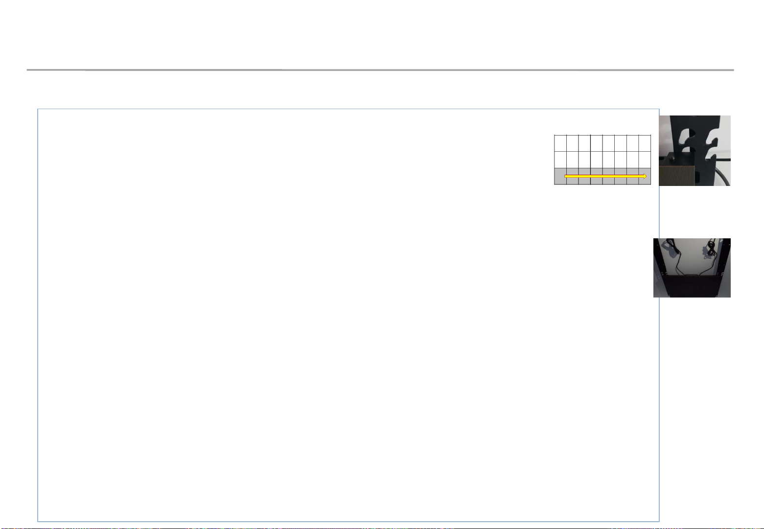
1) If cabinets are installed on a dedicated wall mount, the cabinets are fastened
toward the bottom-left direction.
Sets can only be installed in the left-to-right direction.
→ The set installation direction may be different from the cable
connection direction.
2) After installing all cabinets for one row, connect the signal and power cables and
turn on the sets to check that there is no problem with connection before installing
cabinets for the next row.
3) To connect cables between upper and lower sets, first connect the cables to the
lower sets before assembling the upper sets.
→ If installing upper and lower sets together before connecting cables, it is difficult
to connect cables to the lower cabinets.
3) The two Video Out ports on the Interface Gender should be connected to the first
and last cabinets by using OCM cables so as to ensure proper redundancy
operation.
→ The Interface Gender should be installed in the middle on the left end of the LED
wall. (See page 13.)
→ The distance between the first and last cabinets should be within 2 to 4 m to be
connected with OCM cables.
8. Power and Cable Connection
72
Page 74
Samsung Electronics
8-3. Cabinet installation direction (Full Front fixing)
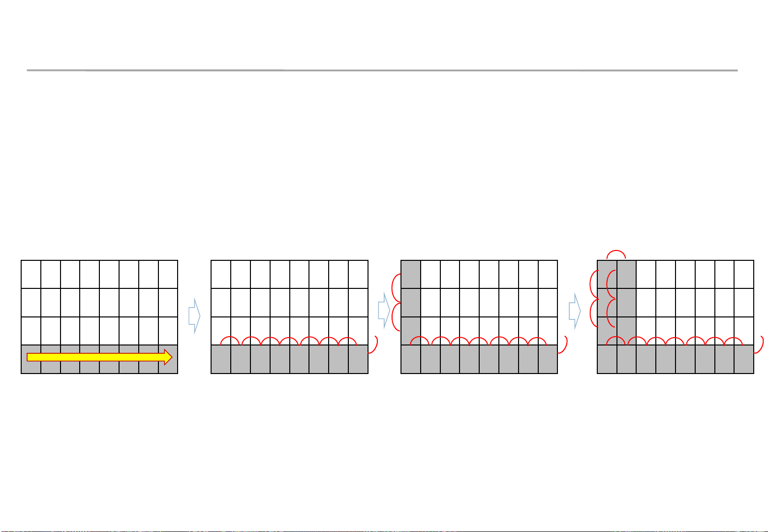
1) For the lowest row, install cabinets in the left-to-right direction.
2) After installing one row of sets is completed, connect signal and power cables between the cabinets.
※ After installation of one row of sets and signal connection are completed, turn on the sets to
check that the installation has been done correctly before installing the next row sets.
3) From the second row, install cabinets vertically (left→right).
1) First row: Install in the
left → right direction
Check that there is no
significant height
difference between
modules inside cabinets.
After connecting all signal/power
cables between the sets, make
sure you turn on the sets to
check that the display on one row
works properly before installing
the upper row.
2) Connect signal/power
cables between the sets
Check that there is no
significant front/back height
difference between cabinets
and the LEDs are arranged in
a straight line.
8. Power and Cable Connection
3) From second row: Install
cabinets and connect
cables vertically
4) Use the same method
to install cabinets and
connect cables
vertically.
73
Page 75
Samsung Electronics
8-4. Cable connection
8. Power and Cable Connection
74
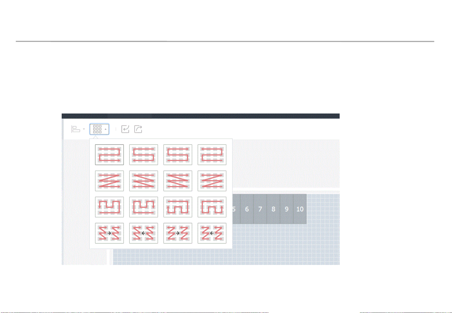
- After installation and connection, automatic sorting can be made on LSM. (automatic sorting for cabinets)
- It is recommended to install the cabinets in automatic sorting order.
Page 76
Samsung Electronics
8-4. Cable connection
75
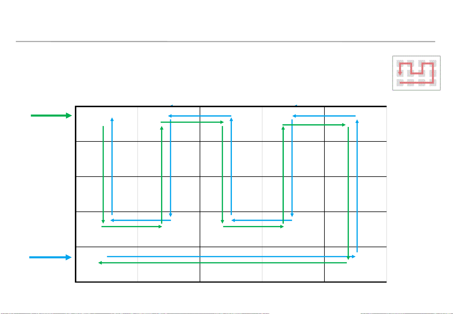
FHD 50/60 Hz screen with IER/IFR would be : 4x4 for P2.0 / 5x5 for P2.5 / 8x8 for P4.0
8. Power and Cable Connection
Forward
Reverse
Case 1:
Ex )
26 19 18 11 10
25 20 17 12 9
24 21 16 13 8
23 22 15 14 7
2 3 4 5 6
Page 77
Samsung Electronics
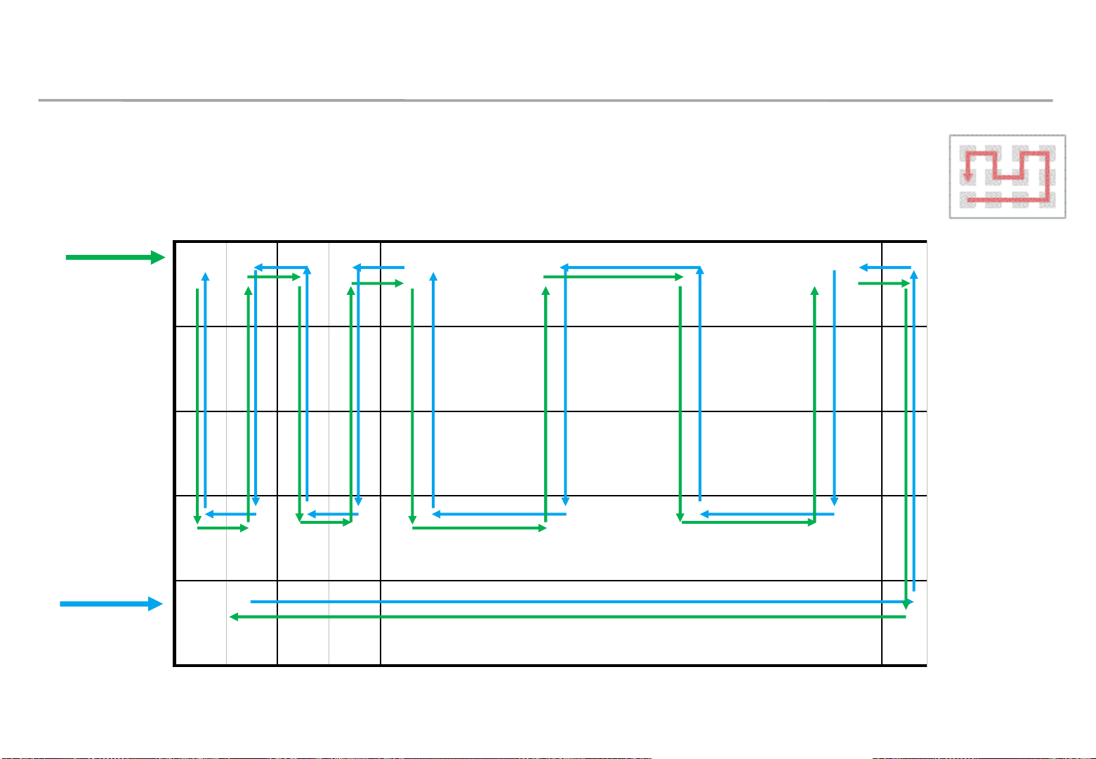
FHD 50/60 Hz screen with IER-F/IFR-F would be : 16x4 for P2.0 / 20x5 for P2.5 / 32x8 for P4.0
(recommended to install mixed with IER/IFR)
76
● ● ●
8. Power and Cable Connection
101
949386
25
100
959287
24
999691
88
23
989790
89
22
2 3 4 5
21
Forward
Reverse
Case 2:
● ● ●
8-4. Cable connection
Ex )
Page 78
Samsung Electronics
9. Seam Adjustment
Black line found on white screen
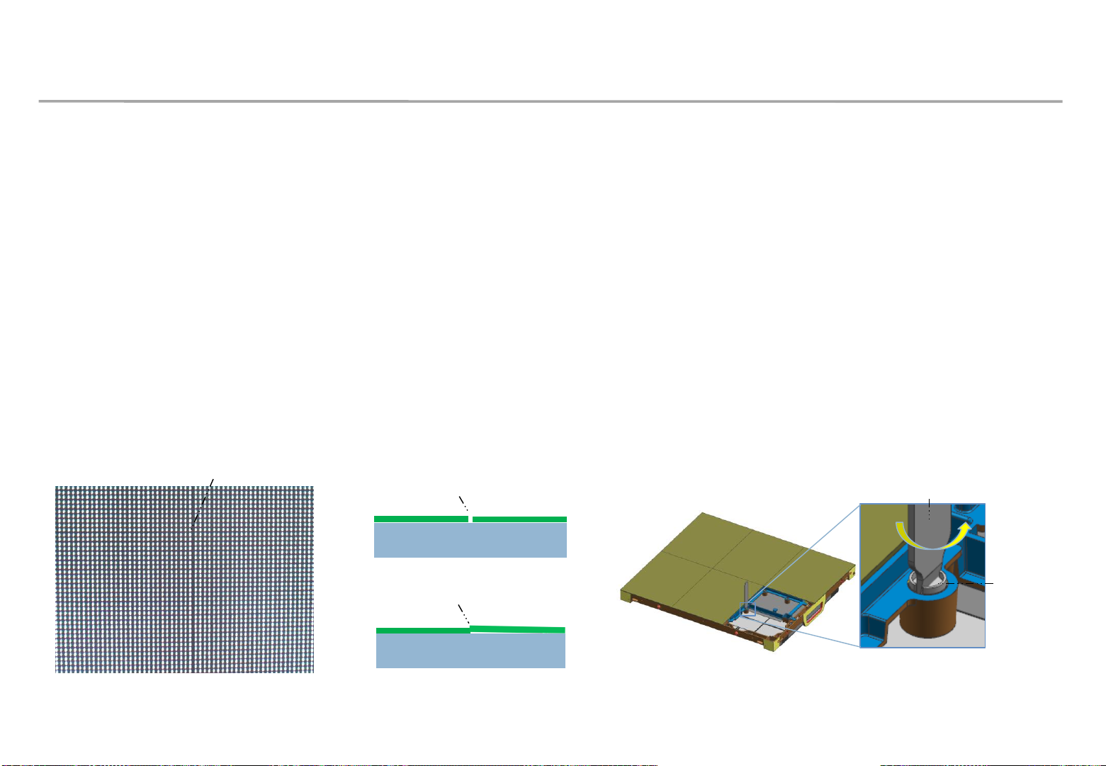
① On the white screen, check that there is no black line found between cabinets. (See Fig.1.)
② Check for a gap or significant height difference between modules. (See Fig.2.)
※ If a gap is found: A black line is visible from all directions.
※ If a significant height difference is found: A white line is visible when viewed from one direction. When viewed from the opposite
direction, a black line is visible.
③ If a gap is found, move the modules with hands, beginning from the outer modules.
④ If a significant height difference is found, disassemble the lower LED modules and adjust the height
by turning the Holder-Magnet with an appropriate tool.
※ If the Holder-Magnet is turned halfway and then turned 360 degrees with the tool, the module height is moved by 0.1 mm (Fig.3).
◇ Checking and adjusting seam
CABINET
LED module 1
LED module 2
Height
difference
CABINET
LED module 1
LED module 2
Gap
Fig.1 Black line Fig.2 Gap / height difference
between modules
Fig.3 Adjusting height difference
Tool
Holder Magnet
Moves by 1
mm per full
turn
77
Page 79
Samsung Electronics
◇ Module disassembly/reassembly
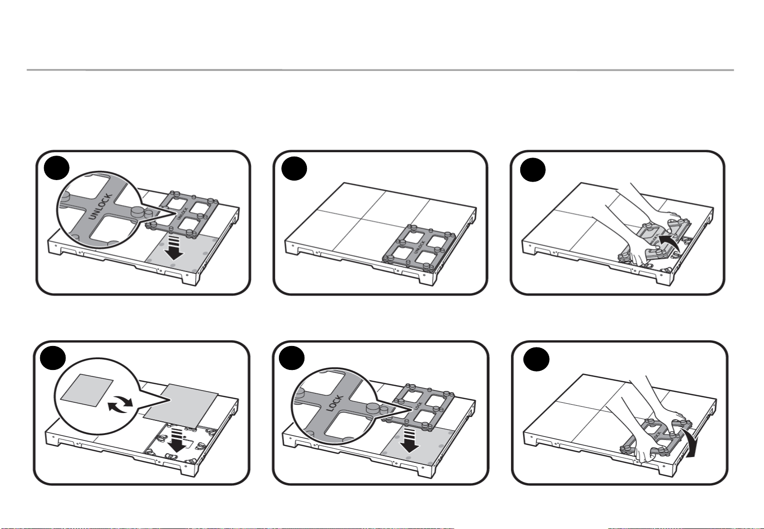
1
2
3
6
54
Hold the JIG with the UNLOCK marking facing up. Put the JIG to the LED module.
Separate the JIG and the module together.
Place the new module on the cabinet.
Hold the JIG with the LOCK marking facing up. Put the JIG to the LED module to lock the module.
9. Seam Adjustment
78
Page 80

Samsung Electronics
IER-F/IFR-F series
Installation Manual
LH0**IER*F*
LH0**IFR*F*
Page 81
Samsung Electronics
Table of Contents
0. Product Information
1. Frame Kit & JIG Configuration
2. IER(IFR) Landscape Installation + IER-F(IFR-F) Extension
2-1. IER + IER-F Extension (Left to Right)
2-2. IER + IER-F Extension (Up to Down)
2-3. IER-F + IER-F Extension (Left to Right)
2-4. IER-F + IER-F Extension (Up to Down)
2-5. IER-F + IER-F L-Type
3. PIVOT Installation
4. Fastening the Cover PCB
80
Page 82
Samsung Electronics
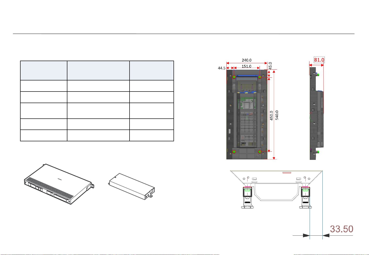
◇ Components of the Frame Kit
(only for installation of IER-F)
0. Product Information
Code Installation
Layout
Remarks
VG-LFR13SWL
1*3 (3 Set)
FRAME F
VG-LFR11SWL
1*1 (1 Set)
FRAME F
VG-LFR11PWF
1*1 (1 Set, PIVOT)
FRAME F
PIVOT
CY-LJRNEF - JIG F
CY-LJRNPF
-
JIG F PIVOT
◇ Cabinet product information / Gap to
the Frame
81
◇ SNOW-1810U (S-Box, I/G)
<S-Box> <I/G>
(Interface Gender)
Page 83
Samsung Electronics
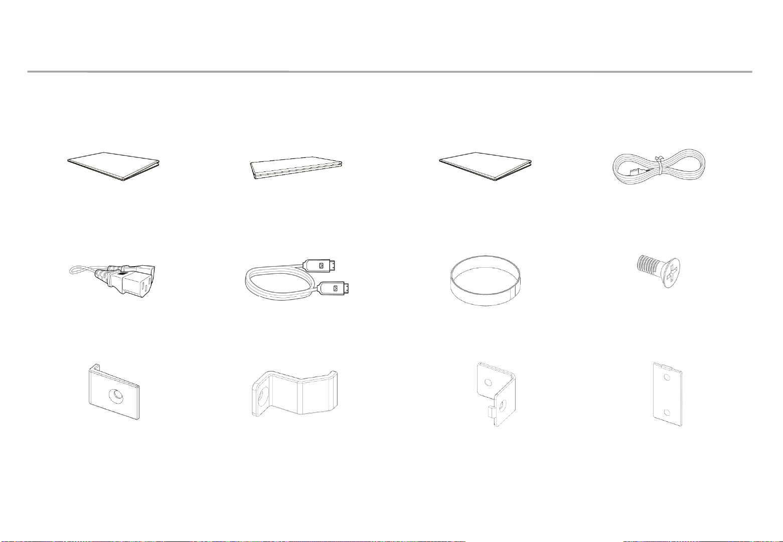
◇ IER-F accessories
0. Product Information
82
Quick Setup Guide
Product Warranty Card
(Not provided in some regions)
Specification
Power Cord
Extension Power Cable OCM Cable
Machine Screws (M4*L10, 13 EA)
PET Tape (W10*L540,1 EA)
COVER PCB (4ea) COVER PCB (6ea) BRACKET LINK (2ea) BRACKET ALIGN (1ea)
Page 84
Samsung Electronics
1. Frame Kit & JIG Configuration
83
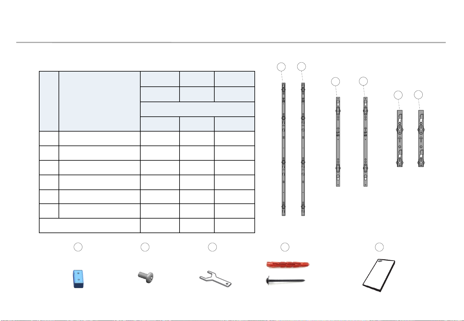
No. Item
Frame F Lv3 Frame F Lv1 Frame F PIVOT
VG-LFR13SWL
VG-LFR11SWL
VG-LFR11PWF
Quantity
1x3 1x1 1x1 PIVOT
ⓐ
ASSY BRACKET SIDE
2 2 2
ⓑ
JOINT V
2 2 -
ⓒ
SCREW (M4) 4 4 -
ⓓ
WRENCH
1 1 -
ⓔ
ASSY ANCHOR SCREW 8 4 4
ⓕ
QUICK INSTALL Guide
1 1 1
Installation Screen Size (mm)
240X1620 240X180 180X240
• Check the following items in each package.
JOINT V
SCREW (M4)
WRENCH
ASSY ANCHOR
SCREW
QSG
b
c d e f
Frame F lv3, Frame F lv1, Frame F PIVOT
a
a
a
a
a
a
Page 85
Samsung Electronics
84
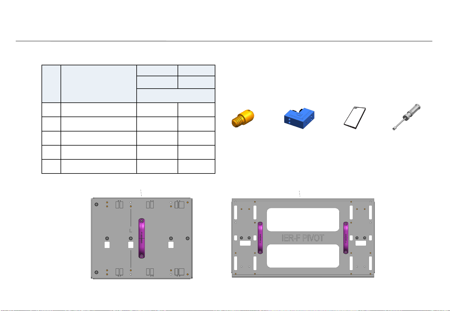
No. Item
JIG F JIG F PIVOT
CY-LJRNEF CY-LJRNPF
Quantity
ⓐ
JIG
1 1
ⓑ
STUD - PEM
- 4
ⓒ
L SUPPORT 1 -
ⓓ
QSG 1 1
ⓔ
D-TOOL 1 1
ⓐ
ⓐ
ⓑ
ⓒ
ⓓ ⓔ
1. Frame Kit & JIG Configuration
JIG F
JIG F PIVOT
D-TOOL
QSG
L SUPPORT
STUD PEM
• Check the following items in each package.
Page 86
Samsung Electronics
2. IER Landscape Installation + IER-F Extension
85
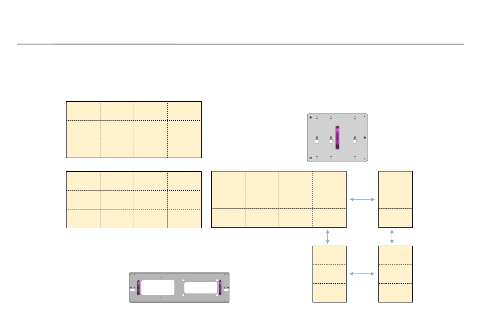
• For installation of IER-F, use 1 x 1 Frame (VG-LFR11SWL) and use the JIG hole gap different from that of IER.
(IER: 270 mm / IER-F: 240 mm)
• As in the following figure, use the JIG F (NEW) for ①, ③, and ④ and use the previous JIG (included in VG-LFR84FWL, VG-LFR5
3FWL, and VG-LFR52SWL) for ②.
• For installation of ②, it is required to move the Stud of JIG (see page 9).
Fig1. IER-F Extension for General Installation of IER
IERIER
IER
IER-F
IER-F
IER-F
Existing JIG (VG-LFR84FWL, VG-LFR53FWL VG-LFR52SWL)②
JIG F: ①,③,④
①
②
③
④
Page 87

Samsung Electronics
• A: Frame gap between IER and IER-F
• B: Frame gap in the IER-F Cabinet
• C: Frame gap between IER-Fs
• The JIG F needs 3 different gaps between IER and IER-F, between IER-F cabinets,
and between IER-Fs.
• In the place with a Stud hole, mount the IER Frame. In the place with two Stud holes,
mount the IER-F Frame.
Fig 2. Locations of JIG F Studs
Fig 3. Gaps between JIG F Studs
Fig 1. IER-F Extension for General Installation of IER
2
A
B
C
IER
FRAME
IER-F FRAME
A
B
C
2. IER Landscape Installation + IER-F Extension
Page 88
Samsung Electronics
2. General Installation of IER + IER-F Extension Frame F
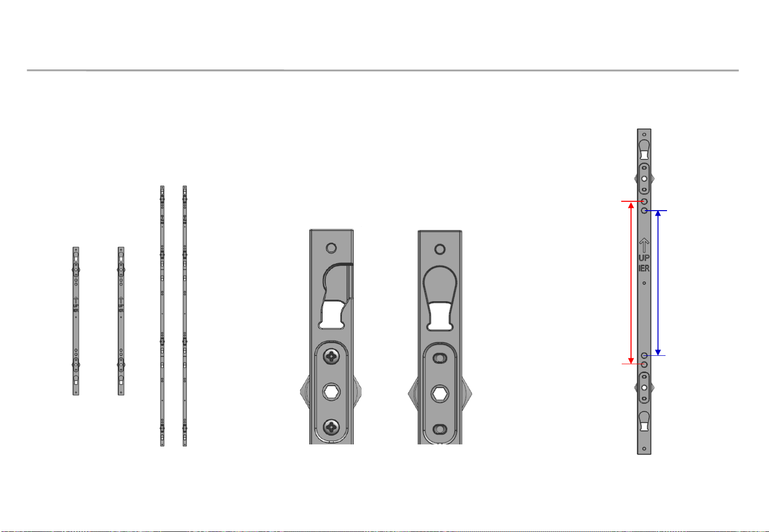
• There are two types of Frame Kits (LV1 & LV3) for installation of IER-F Landscape (Fig 4).
• Different from the IER Frame, be careful upon installation because the Frame F has no direction for left and
right. (Fig 5)
• There are two types of JIG hole gaps (240 mm, 270 mm) on the Frame F, but 240 mm is used mostly for
installation and
• 270 mm is used only when IER-Fs are extended (Fig 6).
2
Fig 5. Different Shapes of IER Frame and F Frame Cabinet Joints (Directional)Fig 4. FRAME F ( LV1, LV3 ) Fig 6. FRAME F JIG HOLE
270mm
240mm
Page 89
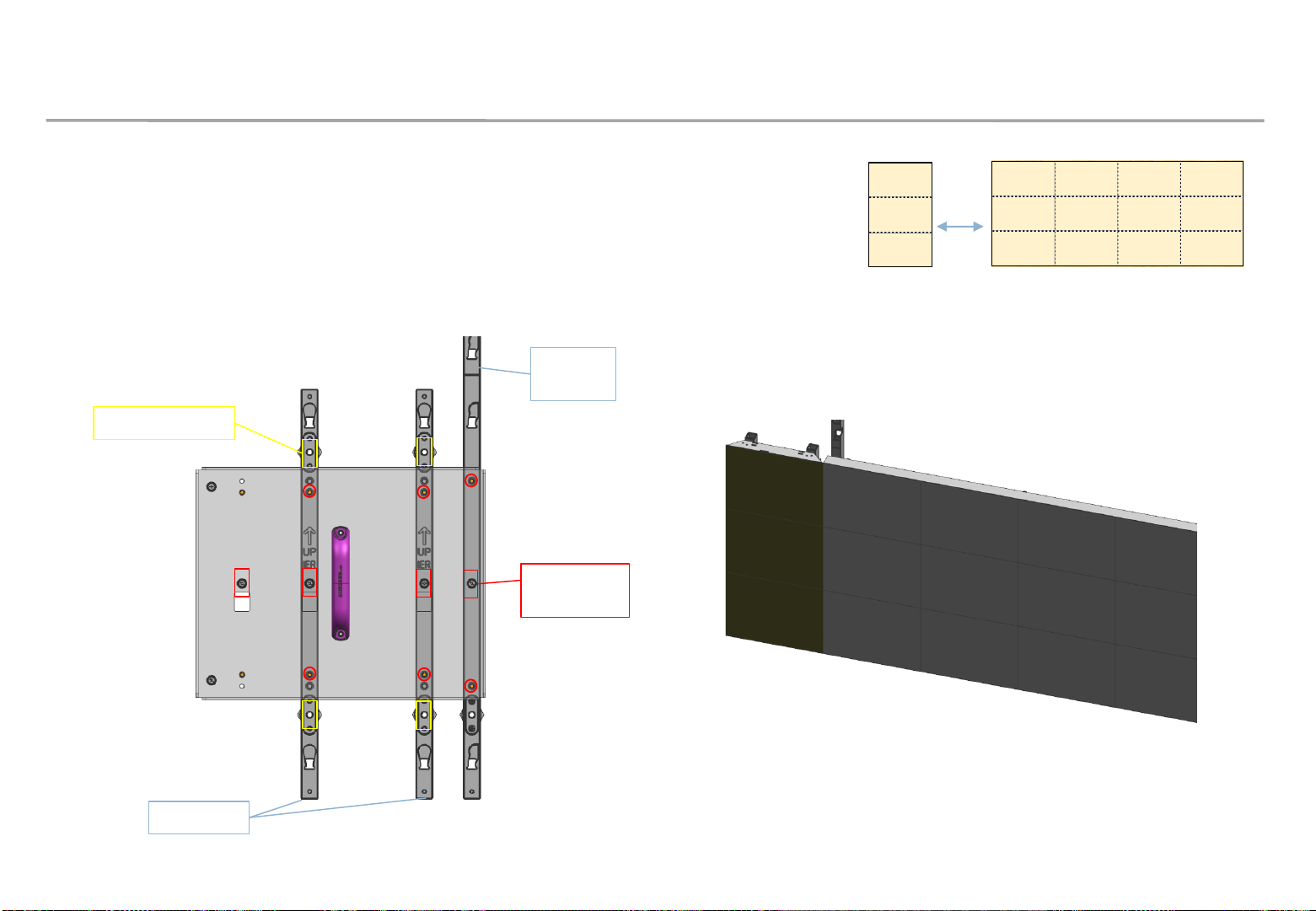
Samsung Electronics
2-1. IER + IER-F Extension (Left to Right)
88
• Use the JIG F when installing the IER-F (“F”) left to right on the installed IER Frame.
• Fasten an IER Frame Side and two Frame Fs on the JIG.
• Align the Stud of JIG with the JIG hole of the Frame, and then fasten the JIG screws.
*Be sure to check the hole locations – IER: 270 mm / IER-F: 240 mm
• Fasten the Frame F to the wall with screws.
Fig 7. Shape of Mounted JIG F
Fig 8. IER-F Installed to the Left of IER
Hole for screw
IER
①
F
F FRAME
IER
FRAME
JIG
SCREW
Page 90
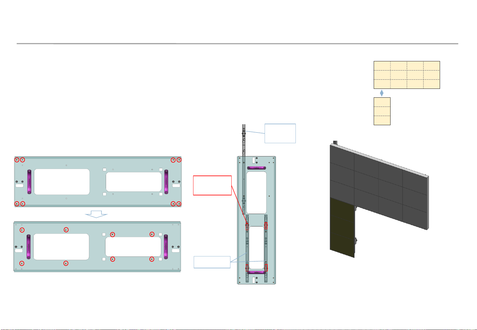
Samsung Electronics
2-2. IER + IER-F Extension (Up to Down)
89
• When F is installed horizontally on the installed IER Frame, use the default JIG of IER
(included in VG-LFR84FWL, VG-LFR53FWL, and VG-LFR52SWL).
• The Stud location of the default JIG must be adjusted (FIG 9).
• Align the JIG Stud with the JIG hole of the Frame.
*Be sure to check the hole locations – IER: 270 mm / IER-F: 240 mm
• Fasten the Frame F to the wall with screws.
Fig 9. Before and After Changing the JIG Stud Location
Screw
Fastening
Fig 10. Shape of Mounted JIG
Fig 11. IER-F Installed to the Bottom of IER
IER
②
IER-F
IER
FRAME
F FRAME
Page 91
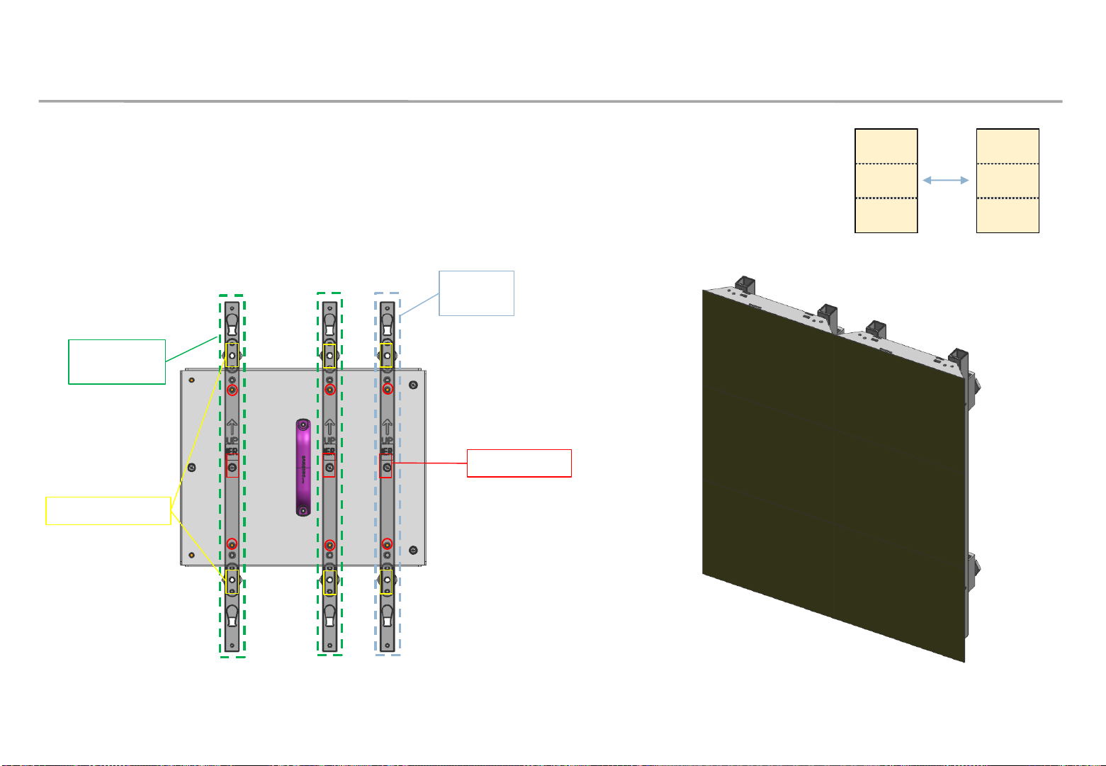
Samsung Electronics
90
2-3. IER-F + IER-F Extension (Left to Right)
• Use the JIG F when installing the F left to right on the installed Frame F.
• Fasten a Frame F and two Frame Fs on the JIG.
• Align the Stud of JIG with the JIG hole of the Frame, and then fasten the JIG screws.
• Fasten the Frame F to the wall with screws.
Fig 12. Shape of Mounted JIG F
Installed
Frame F
Frame F to
Install
Hole for screw
Fig 13. IER-F Installed to the Left of IER-F
③
IER-F
IER-F
JIG SCREW
Page 92
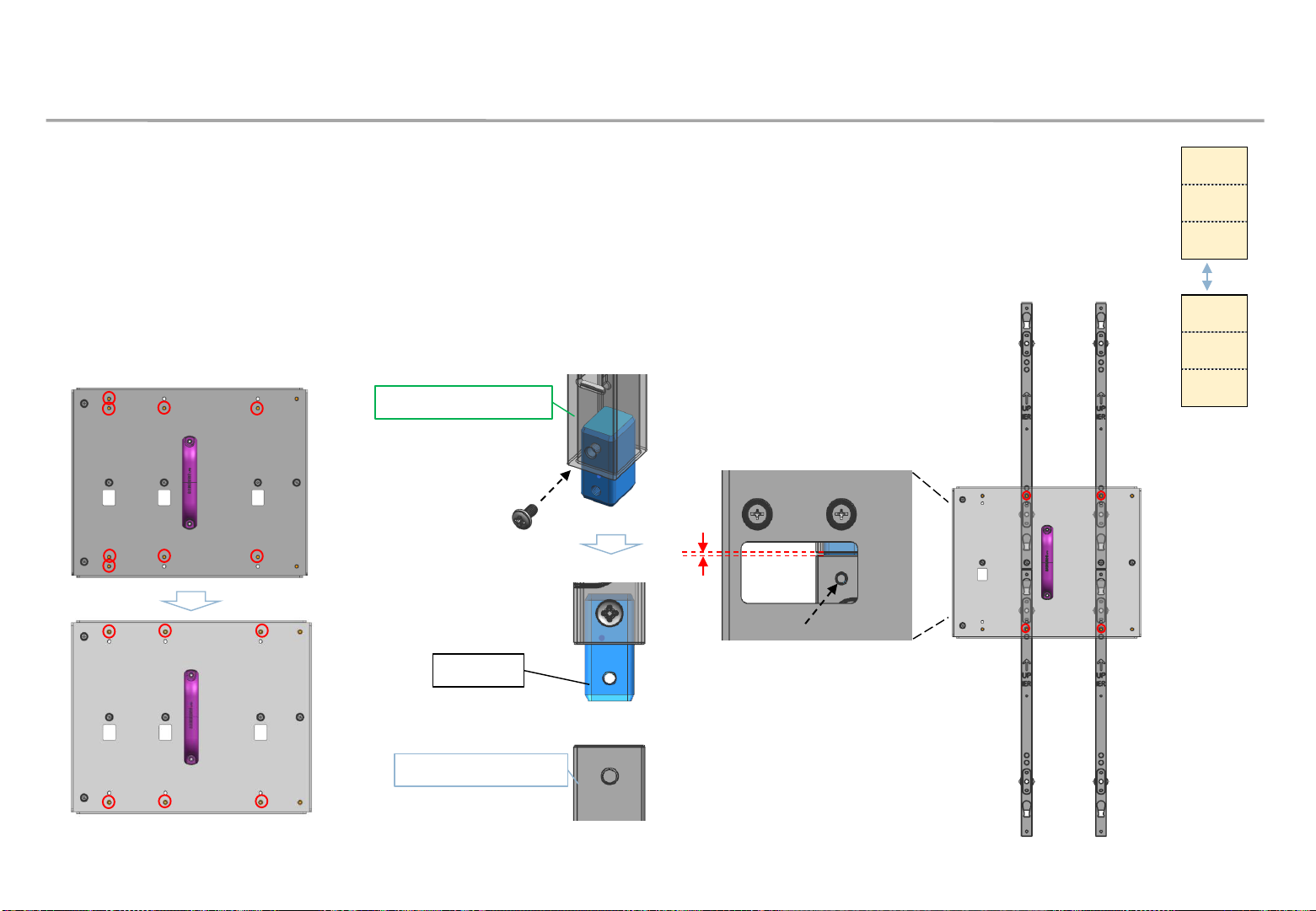
Samsung Electronics
Fastening M4
91
2-4. IER + IER-F Extension (Up to Down)
• Like the vertical extension of the IER Frame, use the Joint V and for this purpose, change the Stud location of the JIG F.
• However, in this case, the frames may not be aligned vertically. Accordingly, the vertical and horizontal checks are
mandatory.
• Extended installation is the same as in IER.
• Fasten the Joint V to the Frame to extend.
• Insert the Joint V of the Frame to extend into the previous Frame for exact positioning, and then fasten the screws.
• The vertical gap between Frames after extension is 1 mm.
Fig 14. Before and After Changing the
JIG Stud Location
Installed Frame
Frame to Install
Fig 15. Vertical Extension
④
IER-F
IER-F
JOINT V
1mm
M4 SCREW
Page 93
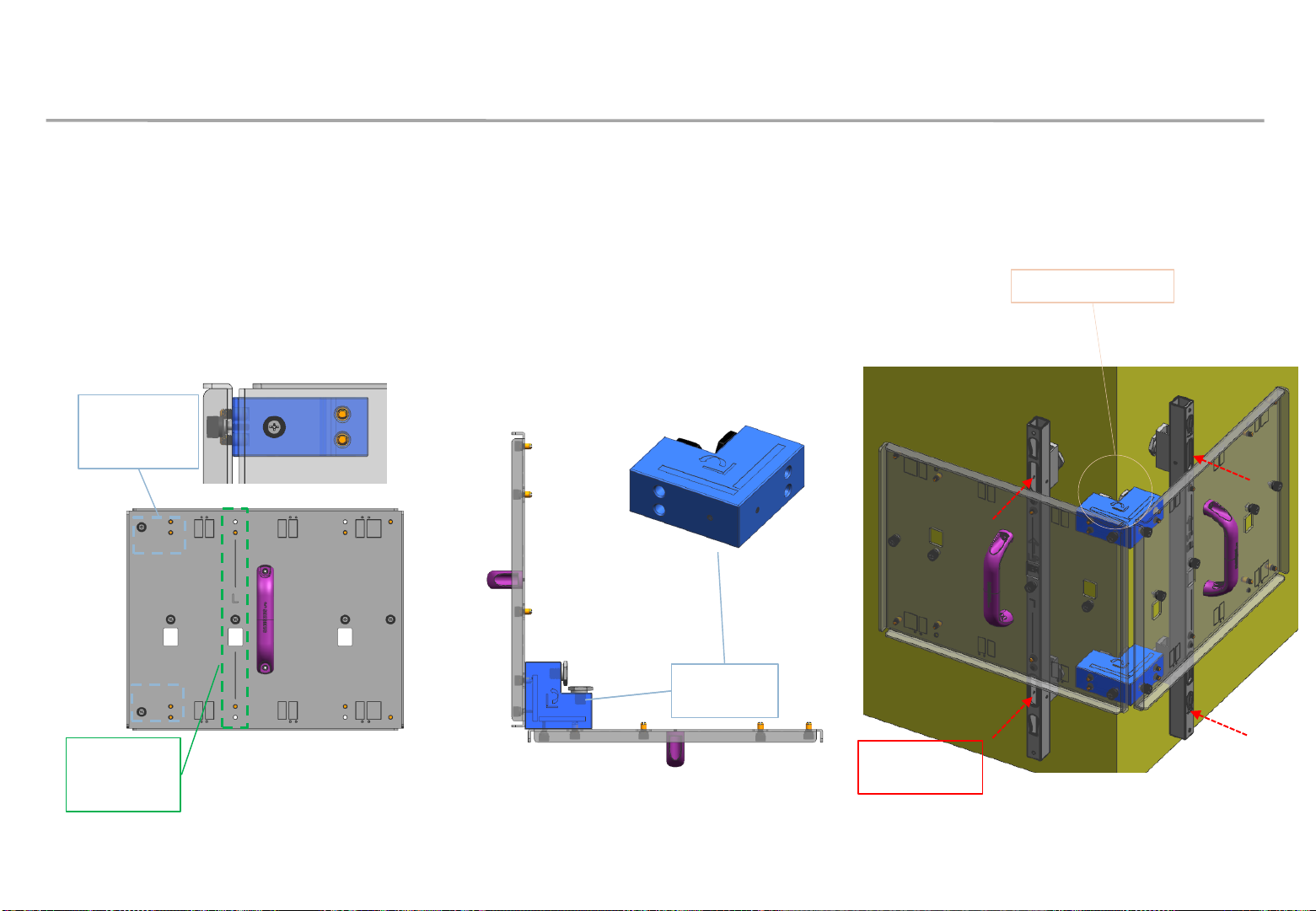
Samsung Electronics
• When there is any L-type installation, install the L-type Frame Kit first of all.
• For L-type installation, use two JIG Fs (CY-LJRNEF).
• Align the fastened Stud with the L Support and then fasten JIG screws. (Fig 17)
• Fasten two Frame F Sides in the L mark of the JIG F.
• Align the Stud of JIG with the JIG hole of the Frame, and then fasten the JIG screws.
• Adhere the inner side of L Support to the wall.
• Fasten the Frame F to the wall with screws.
92
2-5. IER-F + IER-F L-Type Installation
Fig 17. JIG F with the L Support Fastened
Fig 18. Fastened L-type JIG
Fastening
Screws
Fig 16. Fastening Positions of L-type JIG
Fastening
Positions of
Frame F
Fastened
Positions of
L Support
Adhere to the Wall
L
SUPPORT
Page 94
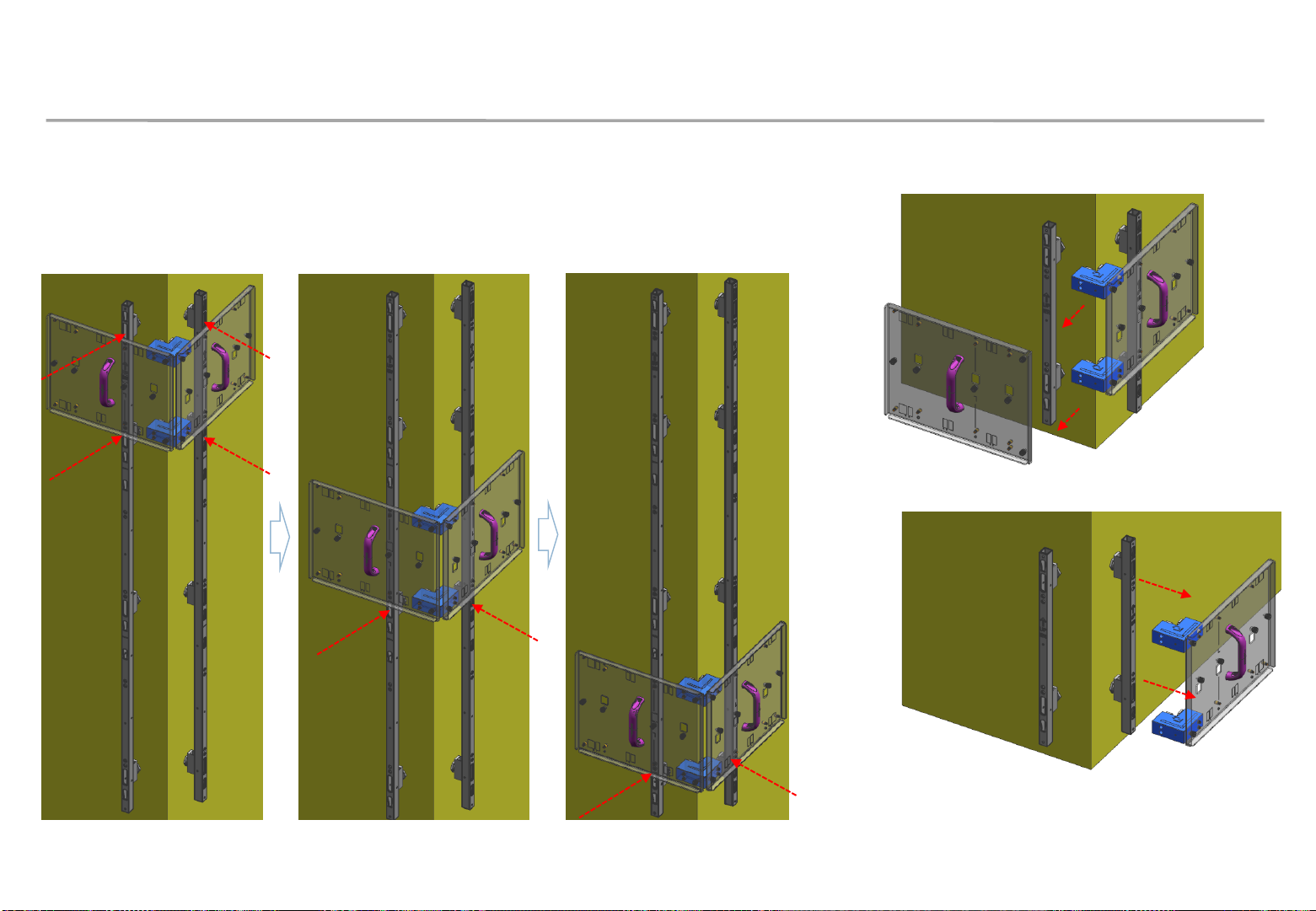
Samsung Electronics
93
• When the Frame F Lv3 is used, repeat JIG fastening and screw fastening from top to bottom.
• After fastening the Frame F to the wall with screws, for detaching the JIG F from the Frame F,
• Remove a JIG F from the L Support and then remove another JIG F.
* Otherwise, be careful because deformation may happen to the JIG F or L Support.
Fig 19. Frame F’s Lv3 L-type Installation Order
Fig 20. L-type JIG Disassembly Order
2-5. IER-F + IER-F L-Type Installation
Page 95
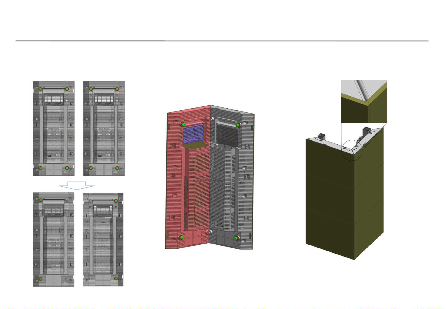
Samsung Electronics
94
Cabinet Installation
• For IER-F L-type installation, use only two among four BOLT ETCs and remove the BOLT-ETCs not in use. (Fig. 21)
• In the joint where two cabinets are met (L-type corner), do not use the BOLT ETC but the outer BOLT-ETC. (Fig. 22)
• During L-type installation, a cabinet protrudes to cover another one. This direction can be determined, noting the L Support mark while installing the
Frame Kit. (Fig. 23)
Fig 21. Removal of BOLT ETC
Fig 22. Rear Panel during L-type Installation
Fig 23. Overlapping Area of L-type Module
2-5. IER-F + IER-F L-Type Installation
Page 96
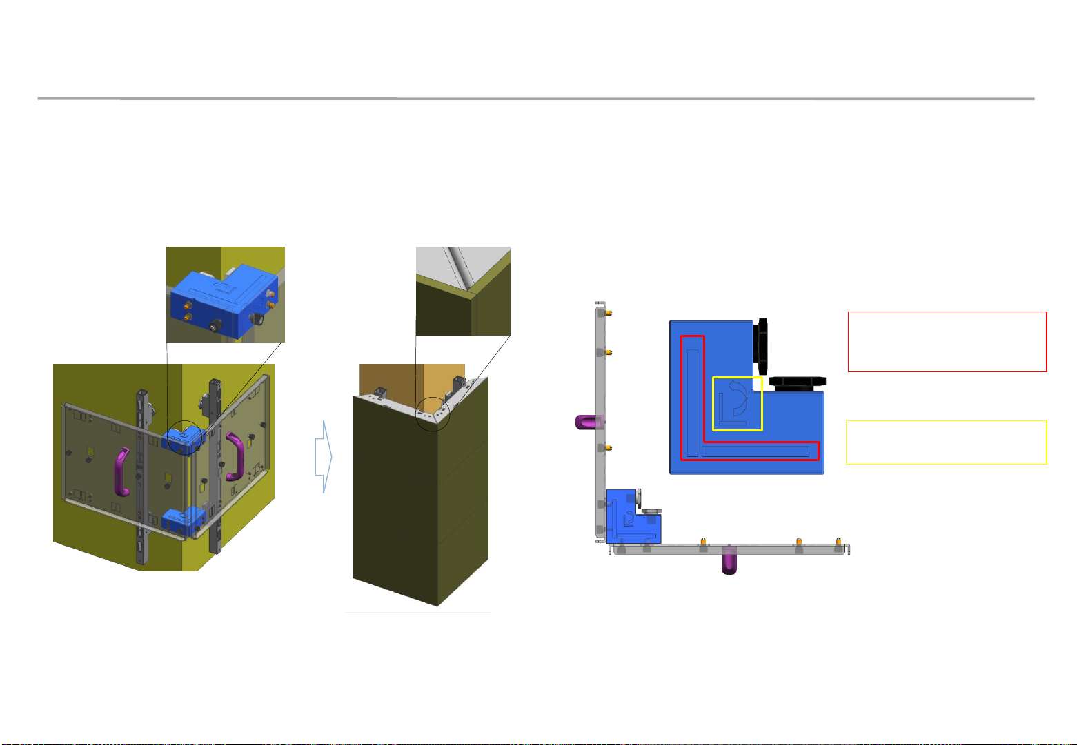
Samsung Electronics
95
• During L-type installation, a module covers another one. This direction can be determined, noting the L Support mark while installing
the Frame Kit.
Fig 24. L Support Marks and Module Overlapping Structure
Fig 25. L Support Marks
Module overlapping direction
from the current JIG point of
view
In case of opposite overlap,
use it upside down.
2-5. IER-F + IER-F L-Type Installation
Cabinet Installation
Page 97
Samsung Electronics
96
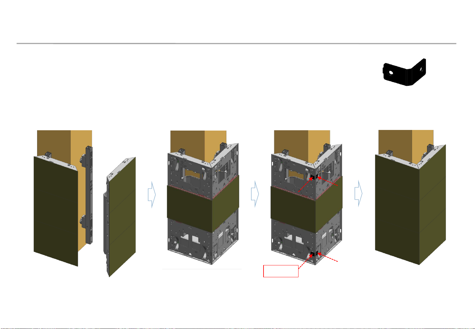
• Mount IER-F Cabinets one by one.
• Remove two (Up and Down) of three modules.
• Assemble the Bracket Link and fasten it with screws through the hole in the L-shaped corner where the module has been
removed. * See next page.
• Connect and assemble the modules (Power, FFC, Cable) to end the L-type installation.
Fig 26. L-type Installation Procedure
Bracket Link
(included in the L-type/Set)
2-5. IER-F + IER-F L-Type Installation
Cabinet Installation
SCREW
Page 98
Samsung Electronics
97
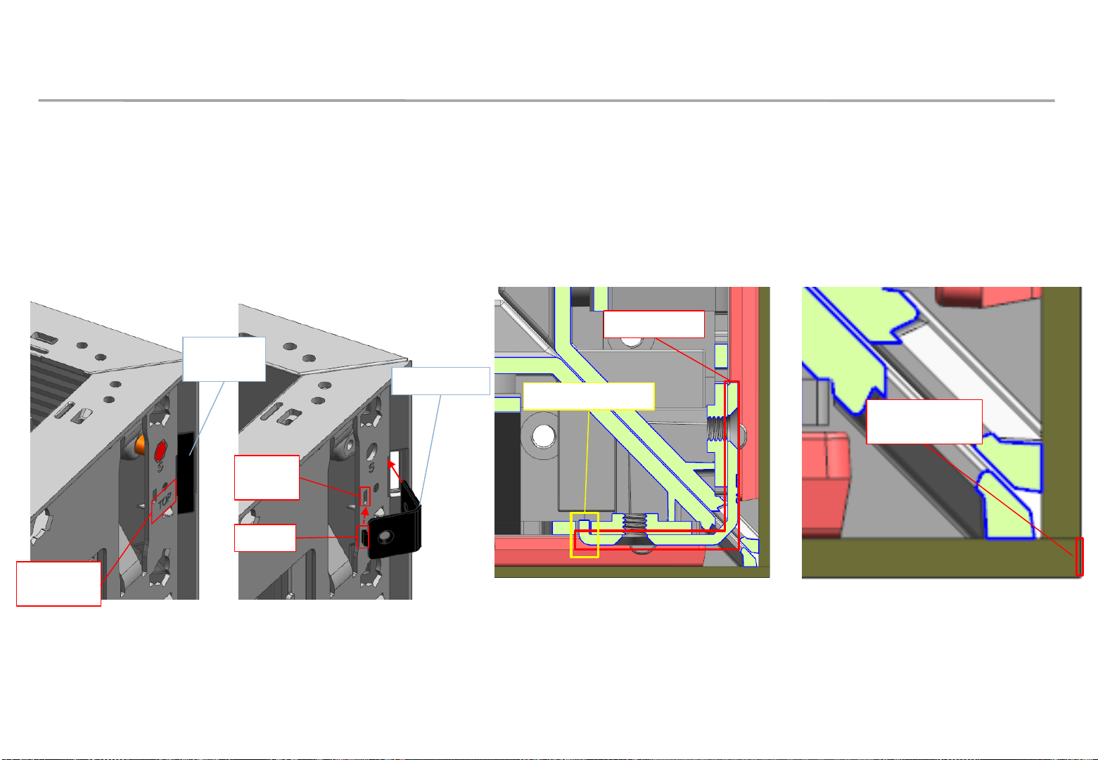
• Remove the Insulator Sheet attached to the Bracket Link’s assembly part of the Cover Rear.
• Check the Bracket Link assembly marks to make sure that the TOP is assembled with the TOP and the BTM with the BTM.
• Only an end of the Bracket Link has the assembly position guide.
• Insert the Bracket Link through the Bracket Link assembly hole on the Cover Rear, fix the Guide, and fasten the Bracket Link with screws.
• At this time, the Guide of the Bracket Link must be fixed through the Guide Hole of the Plate that protrudes outward (Module Side is exposed).
Fig 27. Bracket Link Assembly
Exposure of
Module Side
Fixing the Guide
Fig 28. Bracket Link Direction
2-5. IER-F + IER-F L-Type Installation
BRACKET-LINK
Guide
HOLE
Guide
Bracket Link
Insulator
Sheet
Assembly
Direction
Bracket Link
Page 99

Samsung Electronics
98
• When IER-Fs are stacked upward, fasten the Bracket Align that is used to compensate for Z-axis difference between top and bottom
cabinets.
• Remove the bottom module from the upper cabinet and the top module from the lower cabinet.
• Pass the Bracket Align through the hole of the Cover Rear from the top to connect the up and down cabinets and fasten them with screws.
• Connect the modules again.
* Apply Bracket Align for L-type and all IER-F cabinets that are connected vertically.
Fig 29. IER-F Bracket Align Installation Procedure
Bracket Align
(included in the Set)
2-5. IER-F + IER-F L-Type Installation
BRACKET-ALIGN
Page 100
Samsung Electronics
3. [PIVOT] IER + IER-F Extension
99
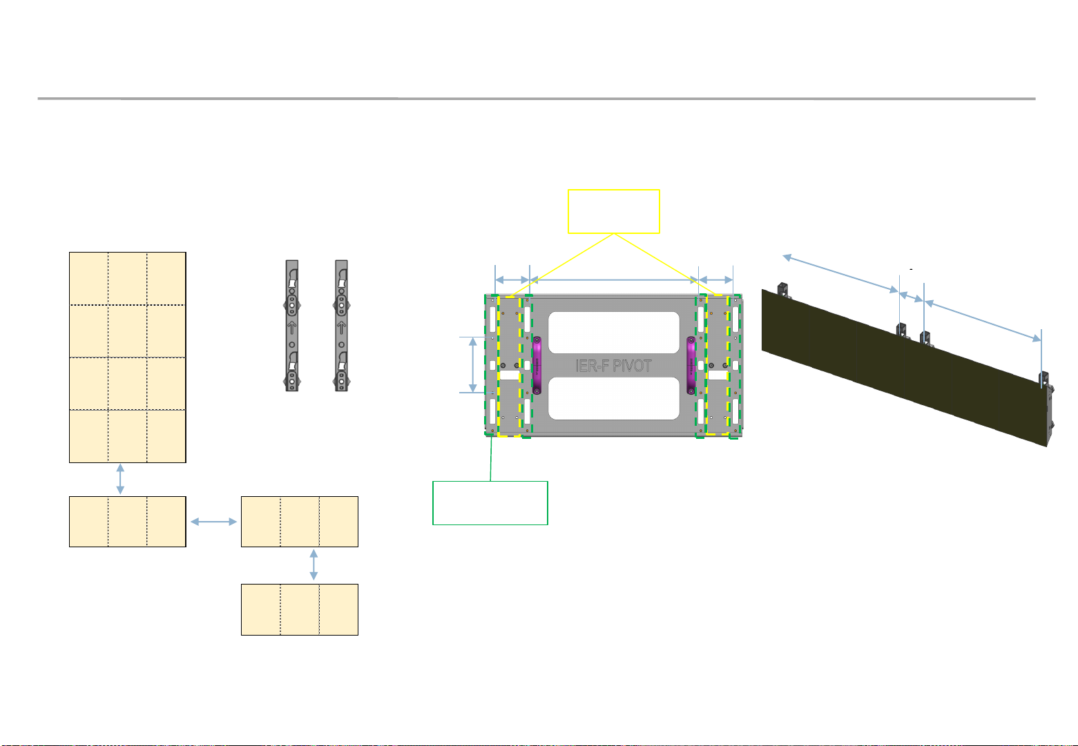
• During installation of IER Pivot, install the IER-F with the JIG F Pivot (CY-LJRNPF).
Fig 1. IER-F Extension and Frame Kit during Installation of the IER Pivot
<Frame Kit for Installation of IER-F Pivot>
• A: Frame gap for extension of IER-Fs (Left to Right)
• B: Frame gap in the IER-F Cabinet
• C: Frame gap for extension of IER-Fs (Up to Down)
IER
IER
-F
IER
-F
①
②
③
IER
-F
A B A
C
A
B
B
IER PIVOT
FRAME
Fig 2. JIG F PIVOT
C
A
B
IER-FRAME F
PIVOT
 Loading...