

Page 1

LFD DISPLAY
User Manual
LE32C LE46C LE55C
The color and the appearance may differ depending on the
product, and the specifications are subject to change without
prior notice to improve the performance.
BN46-00330A-03
Page 2

Table of contents
Before Using the Product
Copyright 5
Safety Precautions 6
Symbols 6
Cleaning 6
Storage 7
Electricity and Safety 7
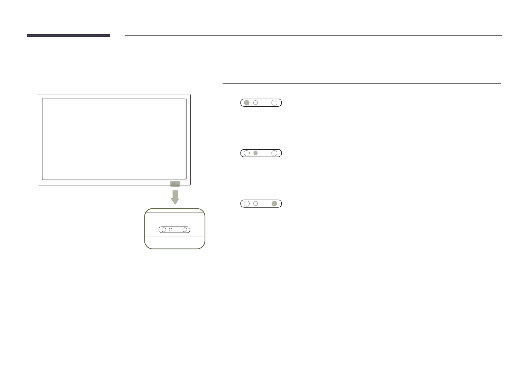
Installation 8
Operation 10
Preparations
Checking the Contents 13
Removing the Packaging
(for LE32C and LE46C models only) 13
Removing the Packaging
(for LE55C models only) 14
Checking the Components 15
Parts 17
Control Panel 17
Rear View 18
Anti-theft Lock 19
Remote Control 20
Connection Using an IR Stereo Cable
(sold separately) 23
Before Installing the Product (Installation
Guide) 24
Tilting Angle and Rotation 24
Ventilation 24
Dimensions 25
Installing the Wall Mount 26
Installing the Wall Mount Kit 26
Wall Mount Kit Specifications (VESA) 27
Remote Control (RS232C) 28
Cable Connection 28
Connection 31
Control Codes 32
Connecting and Using a Source
Device
Before Connecting 41
Pre-connection Checkpoints 41
Connecting to a PC 42
Connection using the D-SUB cable
(Analog type) 42
Connection using a DVI cable (Digital type) 43
Connection Using an HDMI-DVI Cable 43
Connection Using an HDMI Cable 44
Changing the Resolution 45
Changing the Resolution on Windows XP 45
Changing the Resolution on Windows 7 46
Connecting to a Video Device 47
Connection Using the AV Cable 47
Connection Using the component Cable 48
Connection Using an HDMI-DVI Cable 48
Connection Using an HDMI Cable 49
Connecting to an Audio System 50
Connecting the network box
(Sold separately) 51
MagicInfo 51
Input
Source List 54
PIP 55
PIP 55
Source 55
Size 56
Position 56
Transparency 57
Edit Name 57
Source AutoSwitch Settings 58
Source AutoSwitch 58
Primary Source Recovery 58
Primary Source 59
Secondary Source 59
2
Page 3

Table of contents
Picture
Mode 60
Custom 61
Color Tone 62
Color Control 62
Color Temp. 63
Image Lock 63
Auto Adjustment 64
Signal Balance 64
Signal Balance 64
Signal Control 64
Size 65
HDMI Black Level 65
PIP Picture 66
Dynamic Contrast 66
Lamp Control 67
Brightness Sensor 67
Picture Reset 68
Picture
Mode 69
Custom 70
Color Tone 71
Color Temp. 71
Size 72
Digital NR 72
HDMI Black Level 73
Film Mode 73
PIP Picture 74
Dynamic Contrast 74
Lamp Control 75
Brightness Sensor 75
Picture Reset 76
Sound
Mode 77
Custom 78
Auto Volume 78
SRS TS XT 79
Sound Select 79
Speaker Select 80
Sound Reset 80
Setup
Language 81
Time 82
Clock Set 82
Sleep Timer 82
Timer1 / Timer2 / Timer3 82
Holiday Management 82
Menu Transparency 83
Safety Lock 83
Change PIN 83
Lock 83
Energy Saving 84
Video Wall 84
Video Wall 84
Format 85
Horizontal 85
Vertical 86
Screen Position 86
Safety Screen 87
Pixel Shift 87
Timer 88
Bar 88
3
Page 4

Table of contents
Eraser 89
Pixel 89
Side Gray 90
Resolution Select 90
Power On Adjustment 91
OSD Rotation 91
Advanced Settings 92
Temperature 92
Auto Power 92
Button Lock 93
User Auto Color 93
Standby Control 94
Lamp Schedule 94
OSD Display 95
Software Upgrade 96
Setup Reset 97
Reset All 97
Using MDC
Multi Control 98
User Login 104
Auto Set ID 105
Cloning 106
Command Retry 107
Getting Started with MDC 108
Main Screen Layout 109
Menus 109
Screen Adjustment 111
Advanced features 114
Sound Adjustment 116
System Setup 116
Tool Settings 125
Other Functions 128
Group Management 129
Schedule Management 131
Troubleshooting Guide 133
Troubleshooting Guide
Requirements Before Contacting Samsung
Customer Service Center 135
Testing the Product 135
Checking the Resolution and Frequency 135
Check the followings. 136
Specifications
General 141
PowerSaver 144
Preset Timing Modes 146
Appendix
Contact SAMSUNG WORLD WIDE 148
Responsibility for the Pay Service
(Cost to Customers) 156
Not a product defect 156
A Product damage caused by customer's fault 156
Others 156
Correct Disposal 157
Correct Disposal of This Product
(Waste Electrical & Electronic Equipment) 157
Correct disposal of batteries in this product 157
Optimum Picture Quality and Afterimage Burnin Prevention 158
Optimum Picture Quality 158
Prevention of Afterimage Burn-in 159
MDC Program Installation/Uninstallation 99
Installation 99
Uninstallation 99
What is MDC? 100
Connecting to MDC 100
Connection Management 103
Q & A 139
License 161
Terminology 162
4
Page 5
Chapter 01
Before Using the Product
Copyright
The contents of this manual are subject to change without notice to improve quality.
© 2013 Samsung Electronics
Samsung Electronics owns the copyright for this manual.
Use or reproduction of this manual in parts or entirety without the authorization of Samsung Electronics is prohibited.
Microsoft, Windows are registered trademarks of Microsoft Corporation.
VESA, DPM and DDC are registered trademarks of the Video Electronics Standards Association.
Ownership of all other trademarks is attributed to their due owner.
•
An administration fee may be charged if either
-
(a) an engineer is called out at your request and there is no defect in the product
(i.e. where you have failed to read this user manual).
-
(b) you bring the unit to a repair center and there is no defect in the product
(i.e. where you have failed to read this user manual).
•
The amount of such administration charge will be advised to you before any work or home visit is carried out.
5
Page 6
Safety Precautions
Caution
RISK OF ELECTRIC SHOCK DO NOT OPEN
Caution : TO REDUCE THE RISK OF ELECTRIC SHOCK, DO NOT REMOVE COVER. (OR BACK)
THERE ARE NO USER SERVICEABLE PARTS INSIDE.
REFER ALL SERVICING TO QUALIFIED PERSONNEL.
This symbol indicates that high voltage is present inside.
It is dangerous to make any kind of contact with any internal part of this product.
This symbol alerts you that important literature concerning operation and maintenance has been
included with this product.
Symbols
Warning
A serious or fatal injury may result if instructions are not followed.
Caution
Personal injury or damage to properties may result if instructions are not followed.
Cleaning
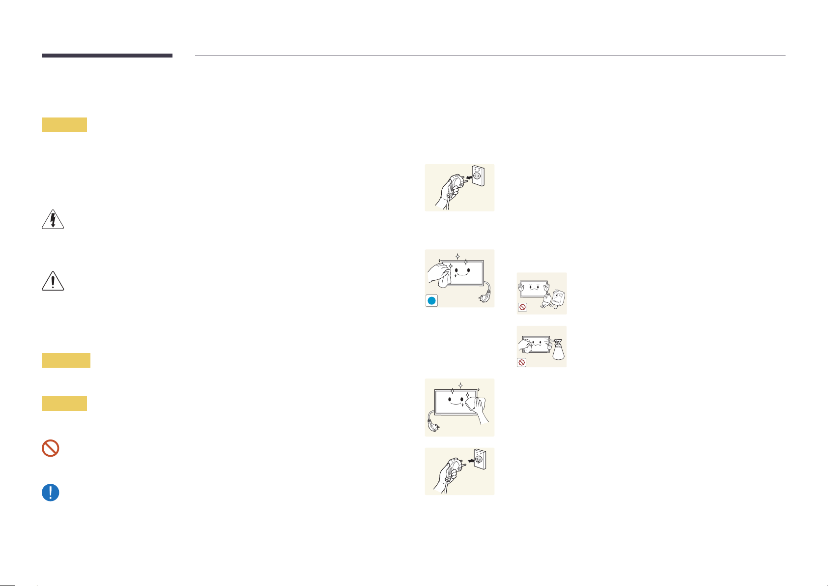
―
Exercise care when cleaning as the panel and exterior of advanced LCDs are easily scratched.
―
Take the following steps when cleaning.
―
The following images are for reference only. Real-life situations may differ from what is shown in the
images.
Power off the product and computer.
1
Disconnect the power cord from the product.
2
―
Hold the power cable by the plug and do not touch the cable with wet
hands. Otherwise, an electric shock may result.
Wipe the product with a clean, soft and dry cloth.
3
•
Do not use detergents that contain alcohol, solvent or
surface-active agents.
!
•
Do not spray water or detergent directly on the product.
Wet a soft and dry cloth in water and wring thoroughly to clean the
4
exterior of the product.
Activities marked by this symbol are prohibited.
Instructions marked by this symbol must be followed.
Connect the power cord to the product when cleaning is finished.
5
Power on the product and computer.
6
6
Page 7

Storage
High-glossy models can develop white stains on the surface if an ultrasonic wave humidifier is used
nearby.
―
Contact Customer Service Center if the inside of the product needs cleaning (service fee will be
charged).
Electricity and Safety
―
The following images are for reference only. Real-life situations may differ from what is shown in the
images.
Connect the power plug to a grounded power socket (type 1 insulated
devices only).
•
An electric shock or injury may result.
!
Do not bend or pull the power cord with force. Be careful not to leave the
power cord under a heavy object.
•
Damage to the cord may result in a fire or electric shock.
Warning
!
Do not use a damaged power cord or plug, or a loose power socket.
•
An electric shock or fire may result.
Do not use multiple products with a single power socket.
•
Overheated power sockets may cause a fire.
Do not touch the power plug with wet hands. Otherwise, an electric shock
may result.
Insert the power plug all the way in so it is not loose.
•
An unsecure connection may cause a fire.
Do not place the power cord or product near heat sources.
•
A fire or electric shock may result.
Clean any dust around the pins of the power plug or the power socket with
a dry cloth.
•
A fire may result.
!
7
Page 8
Caution
Installation
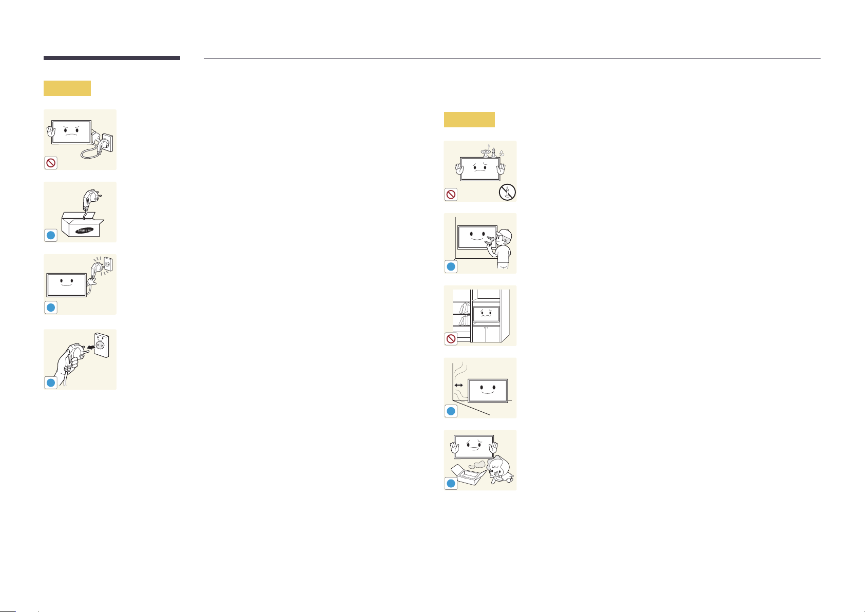
Do not disconnect the power cord while the product is being used.
•
The product may become damaged by an electric shock.
Only use the power cord provided with your product by Samsung. Do not
use the power cord with other products.
•
A fire or electric shock may result.
!
Keep the power socket where the power cord is connected unobstructed.
•
The power cord must be disconnected to cut off power to the product
when an issue occurs.
•
!
!
Note that the product is not completely powered down by using only
the power button on the remote.
Hold the plug when disconnecting the power cord from the power socket.
•
An electric shock or fire may result.
Warning
!
!
DO NOT PLACE CANDLES, INSECT REPELLANTS OR CIGARETTES ON TOP OF
THE PRODUCT. DO NOT INSTALL THE PRODUCT NEAR HEAT SOURCES.
•
A fire may result.
Have a technician install the wall-mount hanger.
•
Installation by an unqualified person can result in an injury.
•
Only use approved cabinets.
Do not install the product in poorly ventilated spaces such as a bookcase or
closet.
•
An increased internal temperature may cause a fire.
Install the product at least 10cm away from the wall to allow ventilation.
•
An increased internal temperature may cause a fire.
Keep the plastic packaging out of the reach of children.
•
Children may suffocate.
!
8
Page 9
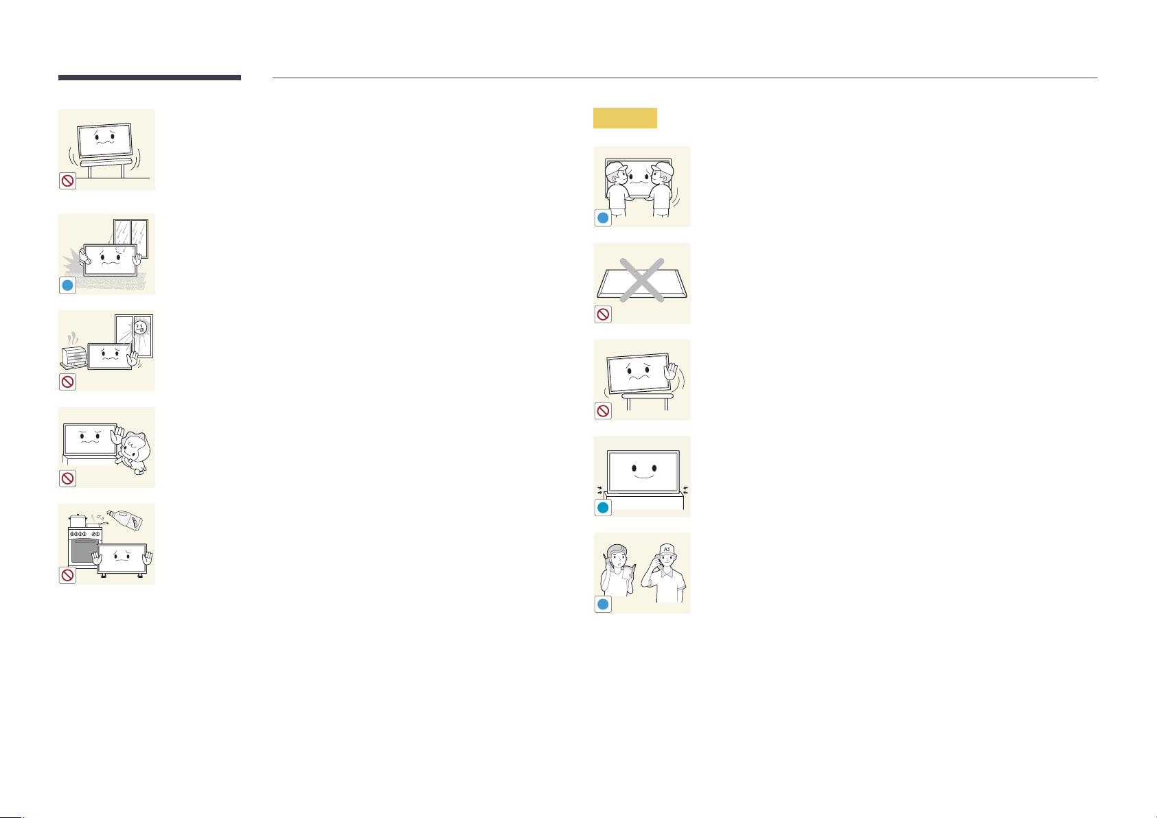
Do not install the product on an unstable or vibrating surface (insecure shelf,
sloped surface, etc.)
•
The product may fall and become damaged and/or cause an injury.
•
Using the product in an area with excess vibration may damage the
product or cause a fire.
Caution
Do not drop the product while moving.
•
Product failure or personal injury may result.
Do not install the product in a vehicle or a place exposed to dust, moisture
!
(water drips, etc.), oil, or smoke.
•
A fire or electric shock may result.
!
Do not set down the product on its front.
•
The screen may become damaged.
Do not expose the product to direct sunlight, heat, or a hot object such as a
stove.
•
The product lifespan may be reduced or a fire may result.
Do not install the product within the reach of young children.
•
The product may fall and injure children.
•
As the front is heavy, install the product on a flat and stable surface.
Edible oil, such as soybean oil, can damage or deform the product.
Do not install the product in a kitchen or near a kitchen counter.
!
When installing the product on a cabinet or shelf, make sure that the
bottom edge of the front of the product is not protruding.
•
The product may fall and become damaged and/or cause an injury.
•
Install the product only on cabinets or shelves of the right size.
Set down the product gently.
•
Product failure or personal injury may result.
Installing the product in an unusual place (a place exposed to a lot of fine
particles, chemical substances or extreme temperatures, or an airport
or train station where the product should operate continuously for an
SAMSUNG
!
extended period of time) may seriously affect its performance.
•
Be sure to consult Samsung Customer Service Center if you want to
install the product at such a place.
9
Page 10

Operation
Warning
There is a high voltage inside the product. Never disassemble, repair or
modify the product yourself.
•
A fire or electric shock may result.
•
Contact Samsung Customer Service Center for repairs.
Do not leave heavy objects or items that children like (toys, sweets, etc.) on
top of the product.
•
The product or heavy objects may fall as children try to reach for the
toys or sweets resulting in a serious injury.
During a lightning or thunderstorm, power off the product and remove the
power cable.
•
A fire or electric shock may result.
Before moving the product, turn off the power switch and disconnect the
power cable and all other connected cables.
•
Damage to the cord may result in a fire or electric shock.
!
If the product generates abnormal sounds, a burning smell or smoke,
disconnect the power cord immediately and contact Samsung Customer
Service Center.
•
An electric shock or fire may result.
!
Do not let children hang from the product or climb on top of it.
•
Children may become injured or seriously harmed.
If the product is dropped or the outer case is damaged, turn off the power
switch and disconnect the power cord. Then contact Samsung Customer
Service Center.
•
Continued use can result in a fire or electric shock.
!
Do not drop objects on the product or apply impact.
•
A fire or electric shock may result.
!
Do not move the product by pulling the power cord or any cable.
•
Product failure, an electric shock or fire may result from a damaged
cable.
If a gas leakage is found, do not touch the product or power plug. Also,
ventilate the area immediately.
•
Sparks can cause an explosion or fire.
!
GAS
Do not lift or move the product by pulling the power cord or any cable.
•
Product failure, an electric shock or fire may result from a damaged
cable.
10
Page 11

Do not use or keep combustible spray or an inflammable substance near
the product.
•
An explosion or fire may result.
!
Ensure the vents are not blocked by tablecloths or curtains.
•
An increased internal temperature may cause a fire.
100
Do not insert metallic objects (chopsticks, coins, hairpins, etc) or objects
that burn easily (paper, matches, etc) into the product (via the vent or input/
output ports, etc).
•
Be sure to power off the product and disconnect the power cord
when water or other foreign substances have entered the product.
Then contact Samsung Customer Service Center.
•
Product failure, an electric shock or fire may result.
Caution
!
-_-
!
!
Leaving the screen fixed on a stationary image for an extended period of
time may cause afterimage burn-in or defective pixels.
•
Activate power-saving mode or a moving-picture screen saver if you
will not be using the product for an extended period of time.
Disconnect the power cord from the power socket if you do not plan on
using the product for an extended period of time (vacation, etc).
•
Dust accumulation combined with heat can cause a fire, electric shock
or electric leakage.
Use the product at the recommended resolution and frequency.
•
Your eyesight may deteriorate.
Do not place objects containing liquid (vases, pots, bottles, etc) or metallic
objects on top of the product.
•
Be sure to power off the product and disconnect the power cord
when water or other foreign substances have entered the product.
Then contact Samsung Customer Service Center.
•
Product failure, an electric shock or fire may result.
Do not hold the product upside-down or move it by holding the stand.
•
The product may fall and become damaged or cause an injury.
Looking at the screen too close for an extended period of time can
deteriorate your eyesight.
!
Do not use humidifiers or stoves around the product.
•
A fire or electric shock may result.
11
Page 12
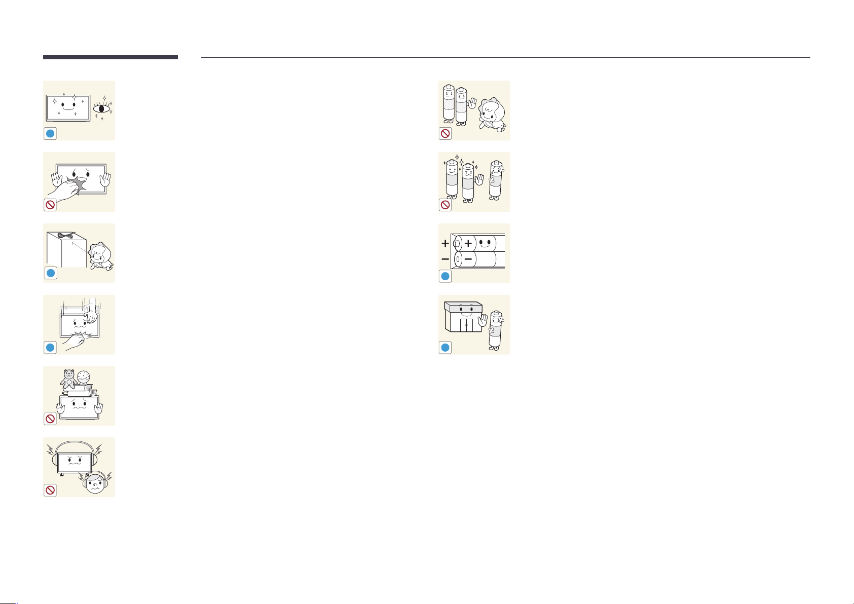
Rest your eyes for more than 5 minutes for every 1 hour of product use.
•
Eye fatigue will be relieved.
!
Be careful that children do not place the battery in their mouths when
removed from the remote control. Place the battery in a location that
children or infants cannot reach.
•
If children have had the battery in their mouths, consult your doctor
immediately.
Do not touch the screen when the product has been turned on for an
extended period of time as it will become hot.
Store small accessories out of the reach of children.
!
Exercise caution when adjusting the product angle or stand height.
•
Your hand or finger may get stuck and injured.
•
Tilting the product at an excessive angle may cause the product to fall
!
and an injury may result.
Do not place heavy objects on the product.
•
Product failure or personal injury may result.
When using headphones or earphones, do not turn the volume too high.
•
Having the sound too loud may damage your hearing.
!
!
When replacing the battery, insert it with the right polarity (+, -).
•
Otherwise, the battery may become damaged or it may cause fire,
personal injury or damage due to leakage of the internal liquid.
Use only the specified standardized batteries, and do not use a new battery
and a used battery at the same time.
•
Otherwise, the batteries may be damaged or cause fire, personal injury
or damage due to a leakage of the internal liquid.
The batteries (and rechargeable batteries) are not ordinary refuse and must
be returned for recycling purposes. The customer is responsible for returning
the used or rechargeable batteries for recycling.
•
The customer can return used or rechargeable batteries to a nearby
public recycling center or to a store selling the same type of the
battery or rechargeable battery.
12
Page 13
Chapter 02
Preparations
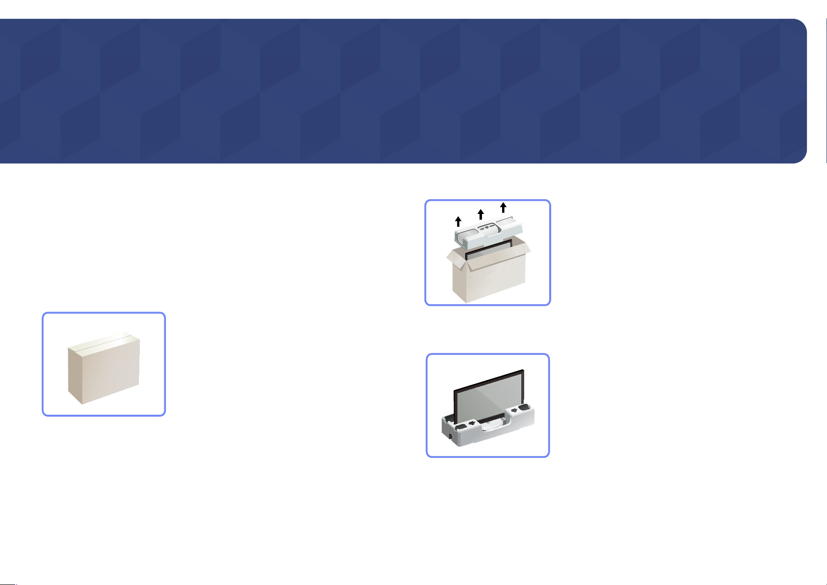
Checking the Contents
Removing the Packaging
(for LE32C and LE46C models only)
―
The following images are for reference only. Real-life situations may differ from what is shown in the
images.
Remove the black locking device at the bottom of the box.
1
Remove the styrofoam from the product.
2
Check the product and remove the styrofoam and plastic bag.
3
―
The appearance of the actual product may differ from the image shown.
―
This image is for reference only.
Store the box in a dry area so that it can be used when moving the product in the future.
4
13
Page 14
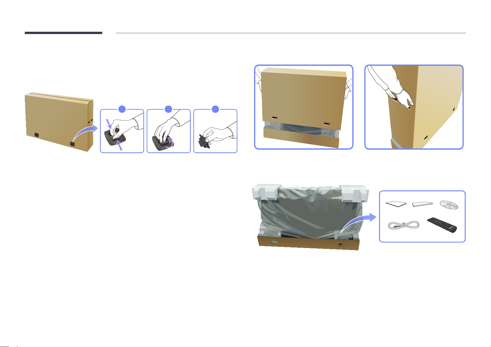
Removing the Packaging (for LE55C models only)
―
The following images are for reference only. Real-life situations may differ from what is shown in the
images.
Remove the black locking device at the bottom of the box.
1
321
Using the grooves in the box, lift and remove the top of the box.
2
Check the components and remove the styrofoam and plastic bag.
3
―
The appearance of actual components may differ from the image shown.
Store the box in a dry area so that it can be used when moving the product in the future.
4
14
Page 15
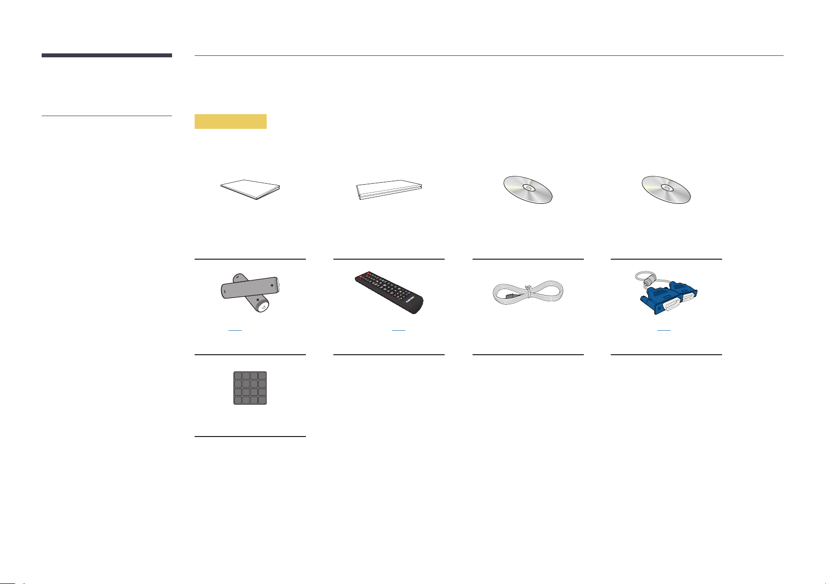
Checking the Components
-
Contact the vendor where you
purchased the product if any
components are missing.
-
The appearance of the components and
items sold separately may differ from the
image shown.
-
A stand is not provided with the product.
To install a stand, you can purchase one
separately.
Components
―
Components may differ in different locations.
Quick setup guide Warranty card
(Not available in some
locations)
-
-
Batteries (P. 21)
(Not available in some locations)
+
+
Remote Control (P.20) Power cord D-SUB cable (P. 42)
User manual MagicInfo Lite Edition Software
CD
Cover Screw
15
Page 16

-
The following items can be purchased
at your nearest retailer.
Items sold separately
Wall-mount Kit Stand RS232C-Stereo cable (P.100) DVI cable (P. 43) HDMI-DVI cable (P. 43)
HDMI cable (P. 44) Video cable (P. 47) Stereo cable (P.23) Component cable (P. 48) RCA stereo cable (P. 50)
RCA cable (P. 47) AV/Component Adapter (P.47) AUDIO Adapter (P.47) LAN cable (P. 101) External sensor Kit (P. 23)
RS232C(IN) Adapter RS232C(OUT) Adapter PIM
16
Page 17
Parts
―
The color and shape of parts may differ from what is shown. Specifications are subject to change without notice to improve
quality.
Control Panel
Buttons Description
Brightness Sensor (Optional)
Automatically detects the surrounding brightness it accordingly.
―
This function is activated only on the models equipped with an auto brightness
sensor.
Power indicator
Shows PowerSaver mode by blinking green
See PowerSaver described in the manual for further information regarding power
saving functions.
―
For energy conservation, turn your LCD Display OFF when it is not needed or
when leaving it unattended for long periods.
Remote sensor
Aim the remote control towards this spot on the LCD Display.
―
Using other display devices in the same space as the remote control of this
product can cause the other display devices to be inadvertently controlled.
17
Page 18

Rear View
―
The color and shape of parts may differ from what is shown. Specifications are
subject to change without notice to improve quality.
Port Description
DVI IN
HDMI IN 1, HDMI IN 2
Connects to a source device using a DVI cable or HDMI-DVI cable.
Connects to a source device using an HDMI cable.
DVI IN
HDMI IN 1
HDMI IN 2
CONTROL IN
IR OUT
LE32C
RGB IN
AV/
COMPONENT IN
IN OUT
RGB/DVI/
HDMI/AV/
COMPONENT
AUDIO
IN OUT
RS232C
CONTROL IN
IR OUT
Supplies power to the external sensor board or receives the light sensor signal.
Receives the remote control signal via the external sensor board and outputs the
signal via LOOP OUT.
RGB IN
AV / COMPONENT IN
RGB / DVI / HDMI / AV / COMPONENT /
Connects to a source device using a D-SUB cable.
Connects to a source device using the AV/component adapter.
Receives sound from a PC via an audio cable.
AUDIO IN
POWER
ON
RGB / DVI / HDMI / AV / COMPONENT /
AUDIO OUT
RS232C IN
Connects to the audio of a source device.
Connects to MDC using an RS232C-stereo adapter.
RS232C OUT
RJ45 MDC
RJ45 MDC
Connects to MDC using a LAN cable.
LE46C, LE55C
RGB IN
AV/
COMPONENT IN
RGB/DVI
HDMI/ AV/
COMPONENT
AUDIO
IN OUT
RS232C
IN OUT
RJ45 MDC
18
Page 19
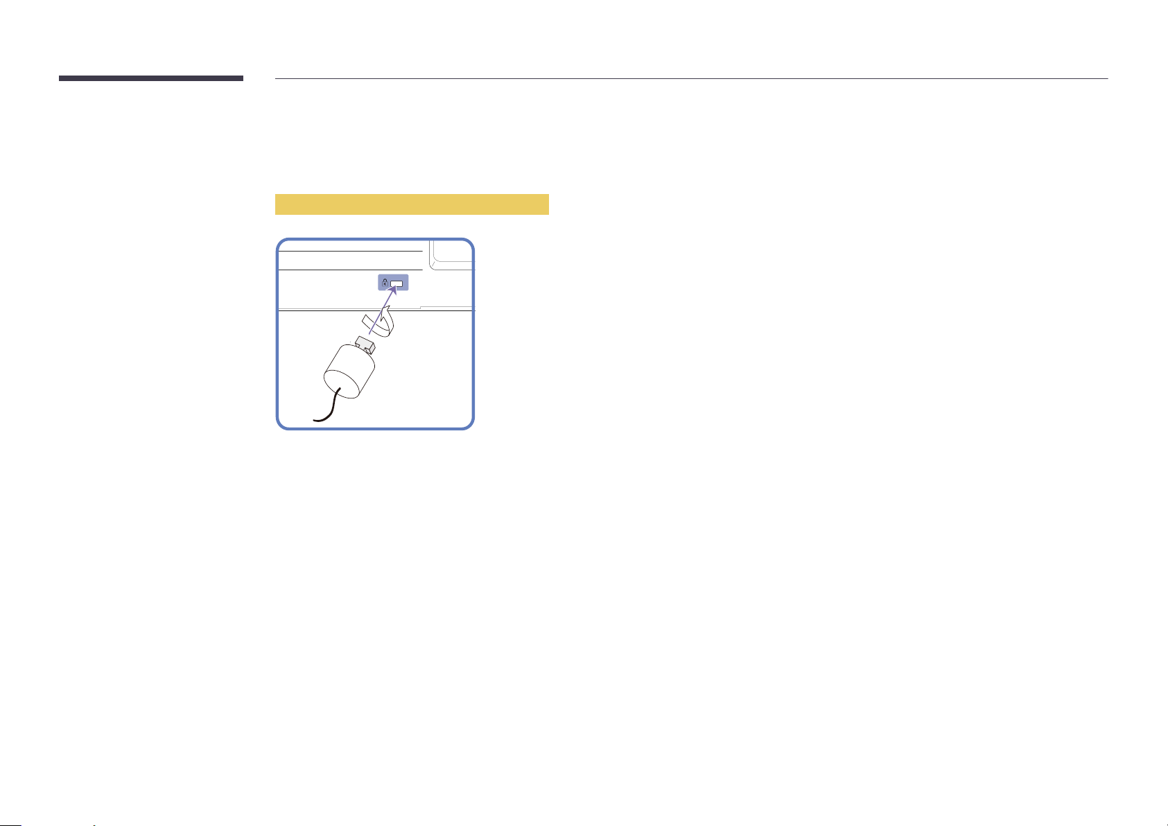
Anti-theft Lock
―
An anti-theft lock allows you to use the product securely even in public places.
―
The locking device shape and locking method depend on the manufacturer. Refer to the user guide provided with your anti-theft locking device for details.
To lock an anti-theft locking device:
Fix the cable of your anti-theft locking device to a heavy object such as a desk.
1
Put one end of the cable through the loop on the other end.
2
Insert the locking device into the anti-theft lock slot at the back of the product.
3
Lock the locking device.
4
-
An anti-theft locking device can be purchased separately.
-
Refer to the user guide provided with your anti-theft locking device for details.
-
Anti-theft locking devices can be purchased at electronics retailers or online.
19
Page 20
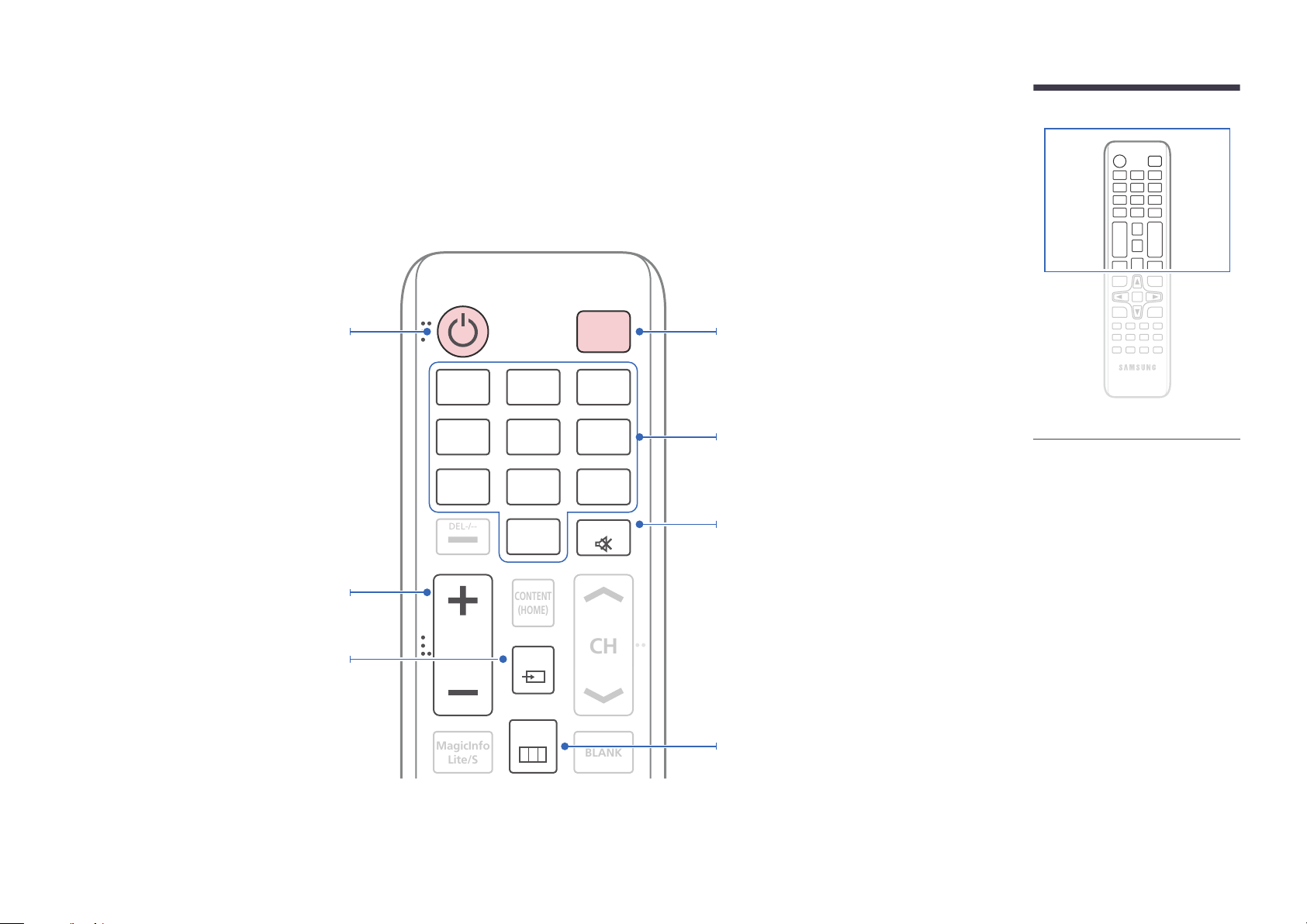
Remote Control
CH
CONTENT
(HOME)
MagicInfo
Lite/S
BLANK
DEL-/--
―
Using other display devices in the same space as the remote control of this product can cause the other display devices to be inadvertently controlled.
Power on the product.
Adjust the volume.
Select a connected source device.
.QZ
1
GHI
4
PRS
7
VOL
ABC
2
JKL
5
TUV
8
SYMBOL
0
SOURCE
MENU
OFF
DEF
3
MNO
6
WXY
9
MUTE
Power off the product.
Enter the password in the OSD menu, or change
the channel.
Mute the sound.
Unmuting the sound: Press MUTE again or press
the volume control (+ VOL -) button.
Display or hide the onscreen display menu, or
return to the previous menu.
-
Remote control button functions may
differ for different products.
20
Page 21

TOOLS
3D
DP
D
Return to the previous menu.
INFO
EXITRETURN
Display information on the screen.
Move to the upper, lower, left or right menu, or
adjust an option's setting.
Activates a highlighted menu item.
Exit the current menu.
MagicInfo Quick Launch Button.
MagicInfo can only be enabled when a network
box is connected.
This button is disabled for products that do not
support MagicInfo.
To place batteries in the remote control
PC
A
MagicInfo
DVI
B
HDMI
C
LOCK
Manually select a connected input source from
PC, DVI, or HDMI..
It sets safe lock function.
-
Remote control button functions may
differ for different products.
21
Page 22
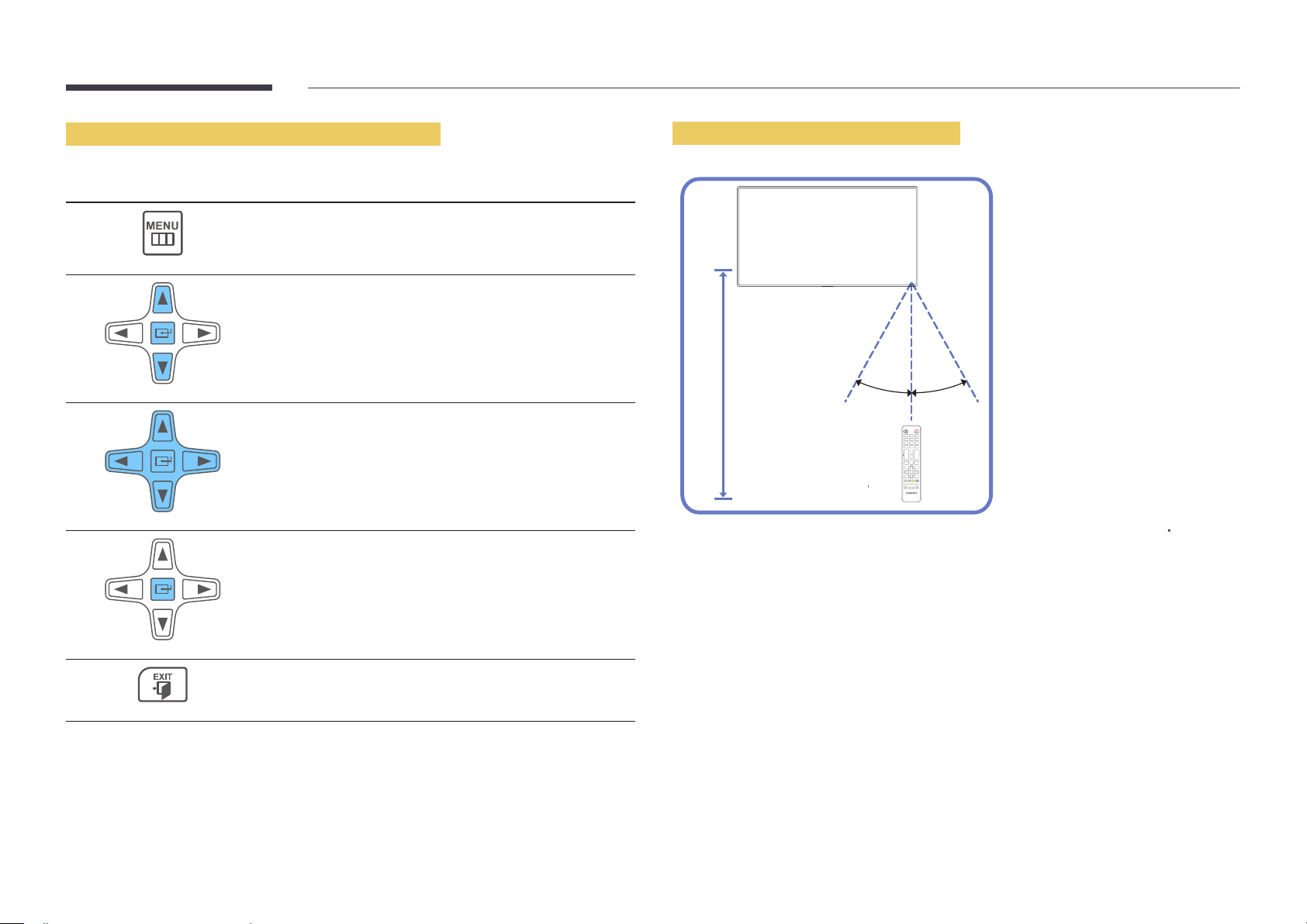
Adjusting the OSD with the Remote Control
Buttons Description
Open the OSD menu.
1
Select from Input, Picture, Sound, Setup or Multi
2
Control in the displayed OSD menu screen.
Remote Control Reception Range
Change settings as desired.
3
Finish setting.
4
Close the onscreen display (OSD) menu.
5
30˚
7m ~ 10m
Use the remote control within 7m to 10m from the sensor on the product at an angle of 30 from the
left and right.
―
Store used batteries out of reach of children and recycle.
―
Do not use a new and used battery together. Replace both batteries at the same time.
―
Remove batteries when the remote control is not to be used for an extended period of time.
30˚
22
Page 23

Connection Using an IR Stereo Cable
(sold separately)
Turn off the device before connecting the External Sensor Kit. After it is connected,
turn on the device.
1 2
Controlling more than one display product using
your remote control
•
Connect the IR OUT port on the product to the CONTROL IN port on the
other display product using the dedicated stereo cable.
•
A command sent from the remote control pointed at product
received by both display products
―
The appearance may differ depending on the product.
1
and 2.
1
will be
Controlling more than one display product using an
external sensor kit (sold separately)
•
A command sent from the remote control pointed at product
which the external sensor kit is connected) will be received by both display
products
―
The appearance may differ depending on the product.
1
and 2.
1
(to
IR OUT
POWER
SOURCE
CONTROL IN
1 2
IR OUT CONTROL IN
CONTROL IN
23
Page 24
Before Installing the Product
(Installation Guide)
―
To prevent injury, this apparatus must be securely attached to the floor/wall in accordance with the installation instructions.
-
Ensure that an authorized installation company installs the wall mount.
-
Otherwise, it may fall and cause personal injury.
-
Make sure to install the specified wall mount.
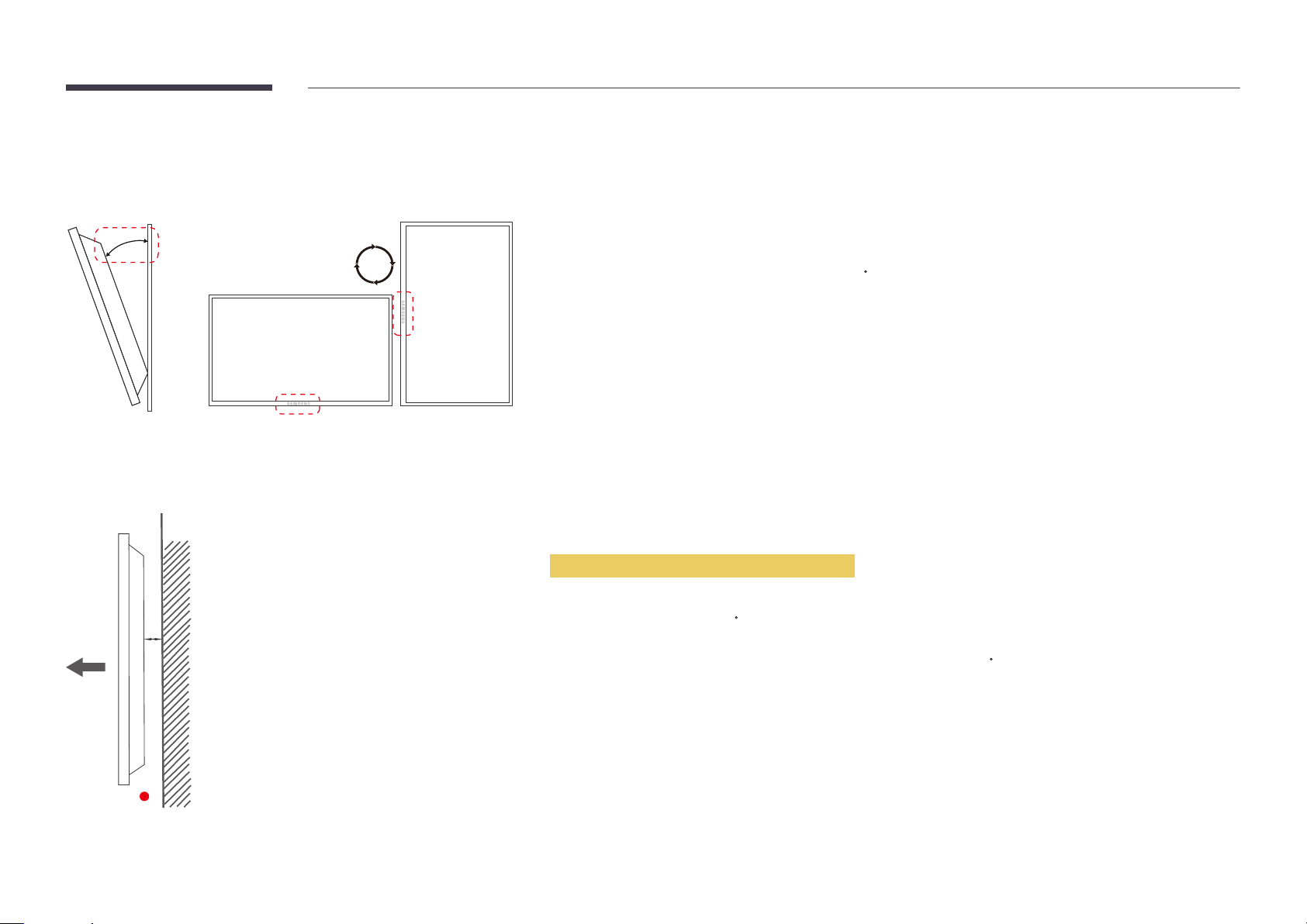
15 ˚
Tilting Angle and Rotation
―
Contact Samsung Customer Service Center for further details.
•
The product can be tilted at a maximum angle of 15
•
To use the product vertically (portrait), turn it clockwise so that the LED is pointing down.
from a perpendicular wall surface.
Ventilation
Installation on a Perpendicular Wall
A Minimum 40 mm
B Ambient temperature: Under 35
•
When installing the product on a perpendicular wall, allow at least 40 mm of space between the product and wall surface
A
for ventilation and ensure that the ambient A temperature is kept below 35
C
C.
B
Figure 1.1 Side view
24
Page 25
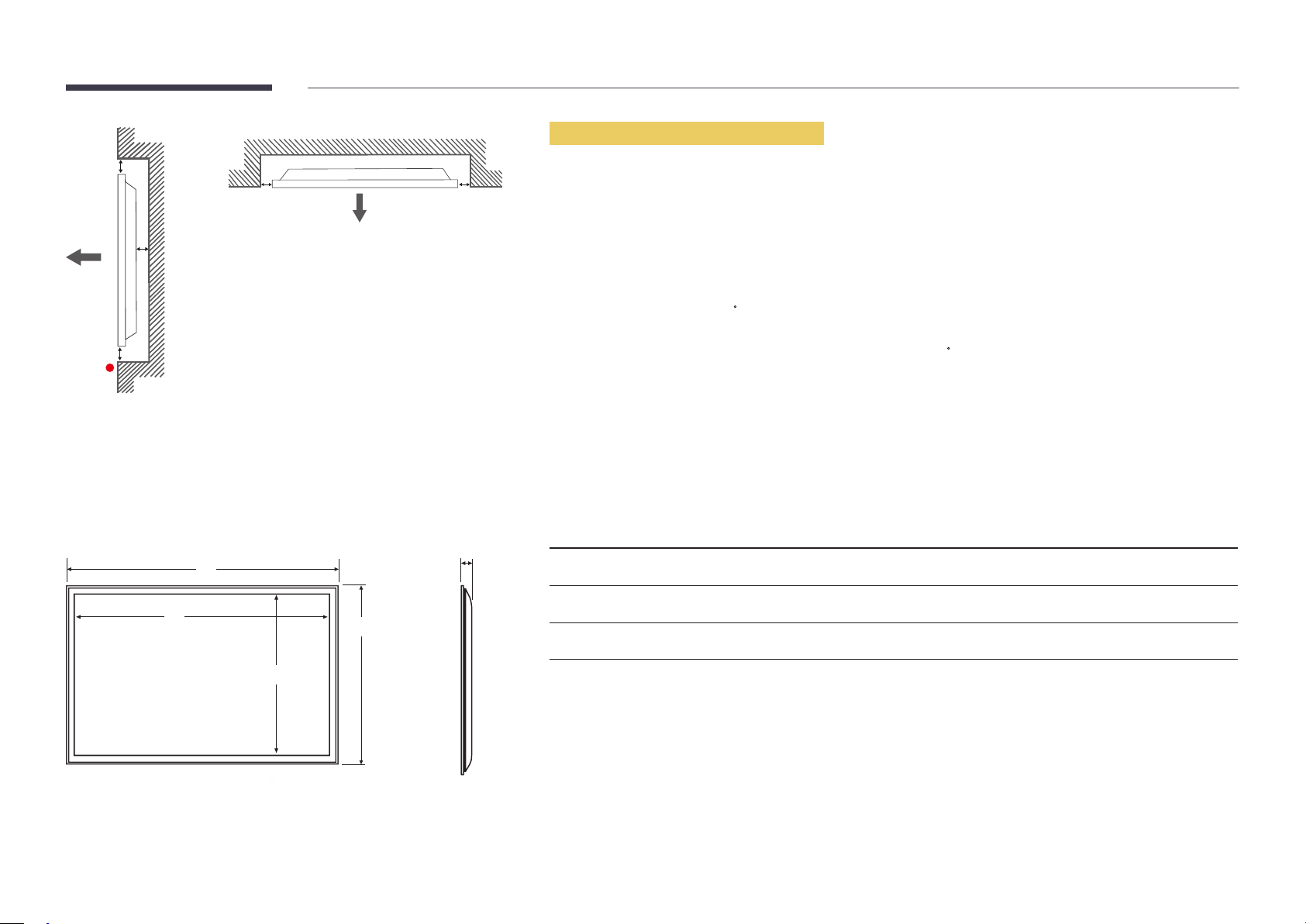
B
A
C
E
Figure 1.2 Side view
Figure 1.3 Side view
D D
Installation on an Indented Wall
―
Contact Samsung Customer Service Center for further details.
Plane view
A Minimum 40 mm
B Minimum 70 mm
C Minimum 50 mm
D Minimum 50 mm
E Ambient temperature: Under 35
―
When installing the product on an indented wall, allow at least the space specified above between the product and wall for
ventilation and ensure that the ambient temperature is kept below 35
C
C.
Dimensions
1
2
3
4
5
Unit: mm (inches)
Model name
LE32C
LE46C
LE55C
―
All drawings are not necessarily to scale. Some dimensions are subject to change without prior notice.
Refer to the dimensions prior to performing installation of your product. Not responsible for typographical or printed errors.
1
744.0 (29.3) 698.4 (27.5) 392.85 (15.5) 452.7 (17.8) 65.9 (2.6)
1061.0 (41.8) 1018.08 (40.1) 572.67 (22.5) 619.8 (24.4) 51.7 (2.0)
1252.4 (49.3) 1209.6 (47.6) 680.4 (26.8) 727.7 (28.6) 51.7 (2.0)
2
3 4
5
25
Page 26
Installing the Wall Mount
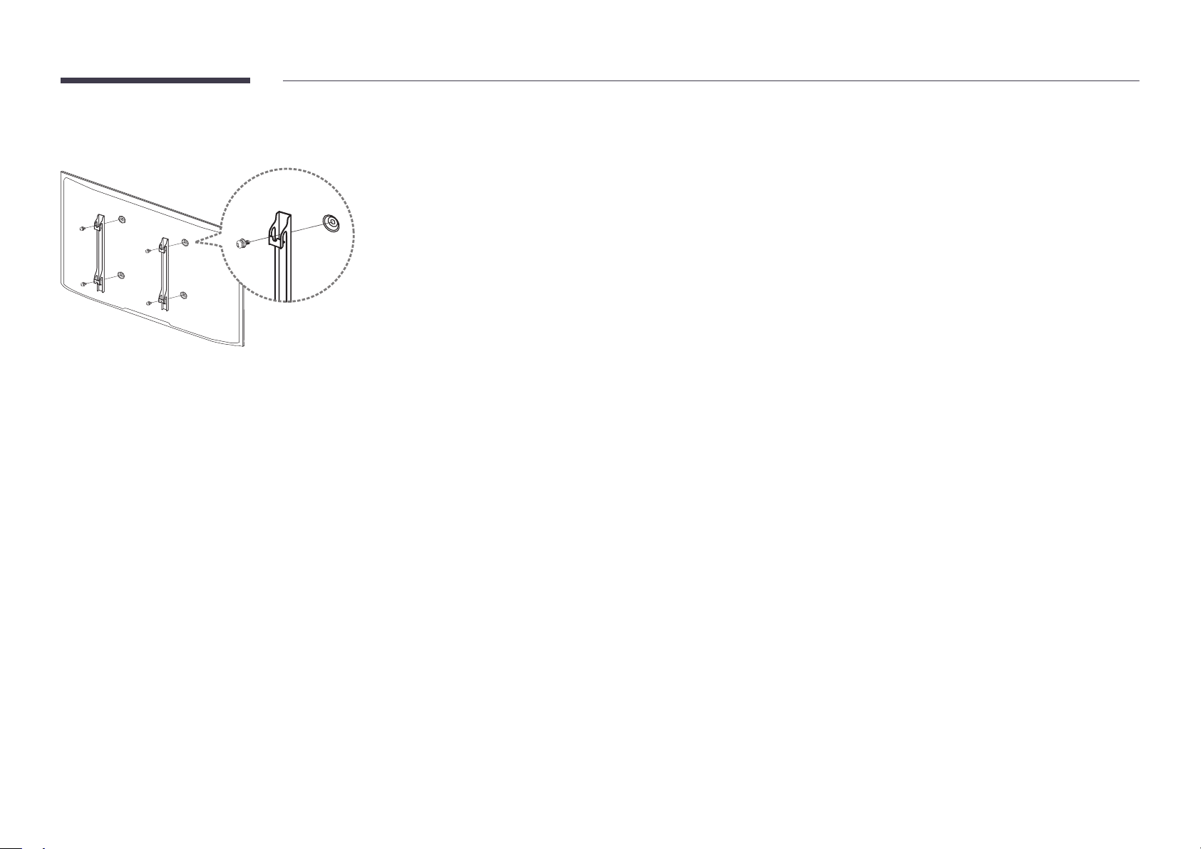
Installing the Wall Mount Kit
The wall mount kit (sold separately) allows you to mount the product on the wall.
For detailed information on installing the wall mount, see the instructions provided with the wall mount.
We recommend you contact a technician for assistance when installing the wall mount bracket.
Samsung Electronics is not responsible for any damage to the product or injury to yourself or others if you elect to install the
wall mount on your own.
26
Page 27
Wall Mount Kit Specications (VESA)
―
Install your wall mount on a solid wall perpendicular to the floor.
Before attaching the wall mount to surfaces other than plaster board, please
contact your nearest dealer for additional information.
If you install the product on a slanted wall, it may fall and result in severe
personal injury.
•
Samsung wall mount kits contain a detailed installation manual and all parts necessary for assembly are provided.
•
Do not use screws that are longer than the standard length or do not comply with the VESA standard screw
specifications. Screws that are too long may cause damage to the inside of the product.
•
For wall mounts that do not comply with the VESA standard screw specifications, the length of the screws may differ
depending on the wall mount specifications.
•
Do not fasten the screws too firmly. This may damage the product or cause the product to fall, leading to personal injury.
Samsung is not liable for these kinds of accidents.
•
Samsung is not liable for product damage or personal injury when a non-VESA or non-specified wall mount is used or the
consumer fails to follow the product installation instructions.
•
Do not mount the product at more than a 15 degree tilt.
•
Always have two people mount the product on a wall.
•
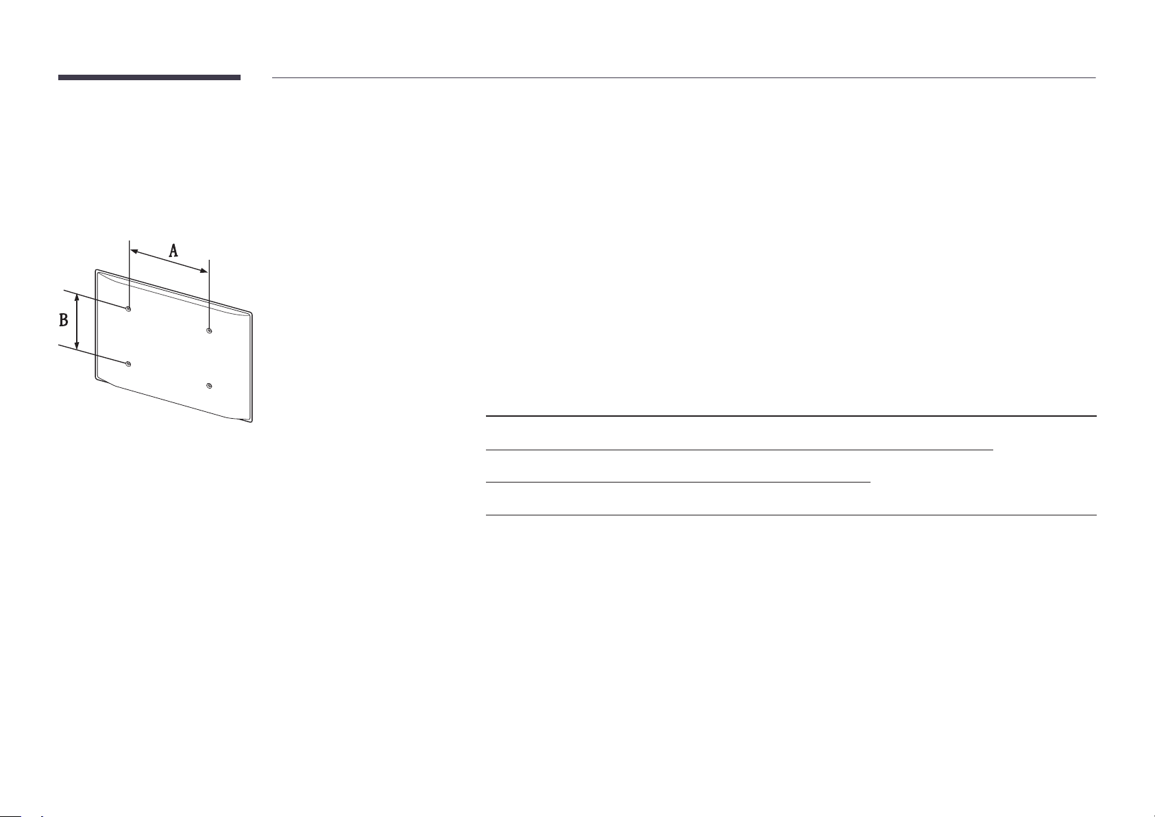
Standard dimensions for wall mount kits are shown in the table below.
Unit: mm (inches)
Model name VESA screw hole specs (A * B) in
Standard Screw Quantity
millimeters
LE32C
LE46C
LE55C
―
Do not install your Wall Mount Kit while your product is turned on. It may result in personal injury due to electric shock.
200 × 200 (7.9 X 7.9) M6
400 × 400 (15.7 X 15.7)
M8
400 × 400 (15.7 X 15.7)
4
27
Page 28

Remote Control (RS232C)
Cable Connection
RS232C Cable
•
Pin assignment
1 2 3 4 5
Interface
Pin
Bit rate
Data bits
Parity
Stop bit
Flow control
Maximum length
RS232C (9 pins)
TxD (No.2), RxD (No.3), GND (No.5)
9600 bps
8 bit
None
1 bit
None
15 m (only shielded type)
6 7 8 9
Pin Signal
1
2
3
4
5
6
7
8
9
Detect data carrier
Received data
Transmitted data
Prepare data terminal
Signal ground
Prepare data set
Send request
Clear to send
Ring indicator
28
Page 29

•
RS232C cable
Connector: 9-Pin D-Sub to Stereo Cable
59
1
6
-P1-
-P1- -P1- -P2- -P2-
3
2
1
-P2-
LAN Cable
•
Pin assignment
1 2 3 4 5 6 7 8
Female Rx
Tx
Gnd
2
3
5
-------->
<--------
----------
3
2
5
Tx
Rx
Gnd
STEREO
PLUG
(3.5ø)
Pin No Standard Colour Signal
1 White and orange TX+
2 Orange TX-
3 White and green RX+
4 Blue NC
5 White and blue NC
6 Green RX-
7 White and brown NC
8 Brown NC
29
Page 30
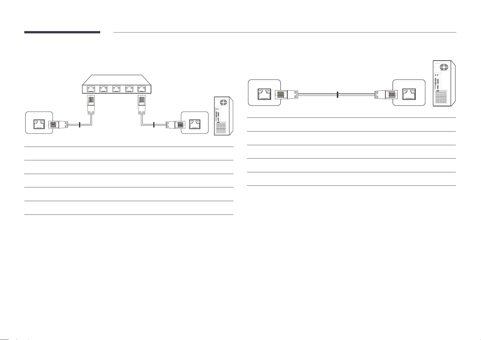
•
Connector : RJ45
Direct LAN cable (PC to HUB)
Cross LAN cable (PC to PC)
HUB
P1P2
RJ45 RJ45 MDC
Signal
TX+
TX-
RX+
RX-
P1
P1 P2 Signal
1 <--------> 1 TX+
2 <--------> 2 TX-
3 <--------> 3 RX+
6 <--------> 6 RX-
P2
Signal
TX+
TX-
RX+
RX-
RJ45
P1 P2
P1 P2 Signal
1 <--------> 3 RX+
2 <--------> 6 RX-
3 <--------> 1 TX+
6 <--------> 2 TX-
30
Page 31
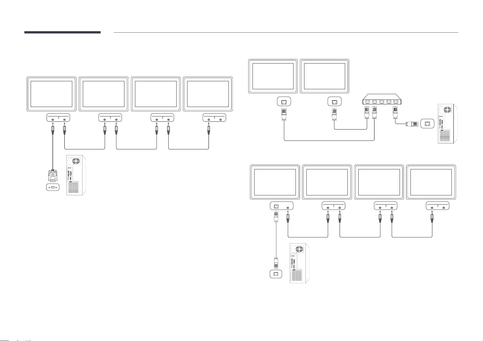
Connection
•
Connection 1
•
Connection 2
RJ45 RJ45
RS232C
IN OUT
RS232C
IN OUT
RS232C
IN OUT
RS232C
IN OUT
•
Connection 3
RS232C
RJ45 RS232C
OUT
IN OUT
RS232C
IN OUT
RS232C
IN OUT
31
Page 32
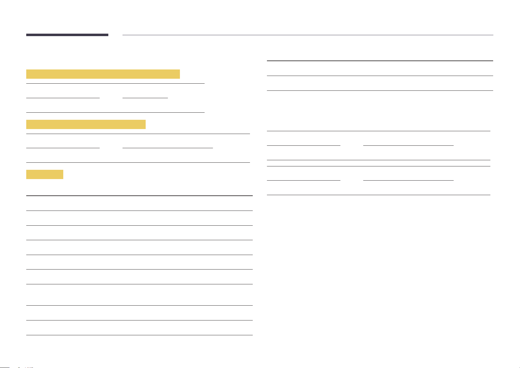
Control Codes
No. Command type Command Value range
Viewing control state (Get control command)
Header Command ID Data length Checksum
0xAA Command type 0
Controlling (Set control command)
Header Command ID Data length Data Checksum
0xAA Command type 1 Value
Command
No. Command type Command Value range
1
2
3
4
Power control 0x11 0~1
Volume control 0x12 0~100
Input source control 0x14 -
Screen mode control 0x18 -
10
11
•
All communications take place in hexadecimals. The checksum is calculated by adding up all
values except the header. If a checksum adds up to be more than 2 digits as shown below
(11+FF+01+01=112), the first digit is removed.
E.g. Power On & ID=0
Header Command ID Data length Data 1 Checksum
0xAA 0x11 1 "Power"
Header Command ID Data length Data 1 12
0xAA 0x11 1 1
•
To control all devices connected by a serial cable simultaneously irrespective of IDs, set the ID as
"0xFE" and transmit commands. Commands will be executed by each device but ACK will not
respond.
Video Wall On 0x84 0~1
Video Wall User Control 0x89 -
5
6
7
8
9
Screen size control 0x19 0~255
PIP on/off control 0x3C 0~1
Auto adjustment control (PC and
BNC only)
Video wall mode control 0x5C 0~1
Safety Lock 0x5D 0~1
0x3D 0
32
Page 33
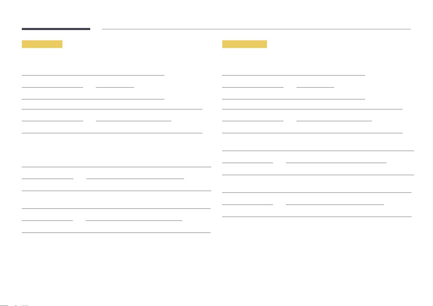
Power control
Volume control
•
Function
A product can be powered on and off using a PC.
•
Viewing power state (Get Power ON / OFF Status)
Header Command ID Data length Checksum
0xAA 0x11 0
•
Setting power ON/Off (Set Power ON / OFF)
Header Command ID Data length Data Checksum
0xAA 0x11 1 "Power"
"Power": Power code to be set on a product.
1: Power ON
0: Power OFF
•
Ack
Header Command ID Data length Ack/Nak r-CMD Val1 Checksum
0xAA 0xFF 3 'A' 0x11 "Power"
"Power": Power code to be set on a product.
•
Nak
Header Command ID Data length Ack/Nak r-CMD Val1 Checksum
•
Function
The volume of a product can be adjusted using a PC.
•
Viewing volume state (Get Volume Status)
Header Command ID Data length Checksum
0xAA 0x12 0
•
Setting the volume (Set Volume)
Header Command ID Data length Data Checksum
0xAA 0x12 1 "Volume"
"Volume": Volume value code to be set on a product. (0-100)
•
Ack
Header Command ID Data length Ack/Nak r-CMD Val1 Checksum
0xAA 0xFF 3 'A' 0x12 "Volume"
"Volume": Volume value code to be set on a product. (0-100)
•
Nak
Header Command ID Data length Ack/Nak r-CMD Val1 Checksum
0xAA 0xFF 3 'N' 0x12 "ERR"
0xAA 0xFF 3 'N' 0x11 "ERR"
"ERR" : A code showing what error has occurred.
"ERR" : A code showing what error has occurred.
33
Page 34
Input source control
•
Function
The input source of a product can be changed using a PC.
•
Viewing input source state (Get Input Source Status)
Header Command ID Data length Checksum
0xAA 0x14 0
•
Setting the input source (Set Input Source)
Header Command ID Data length Data Checksum
0xAA 0x14 1 "Input Source"
"Input Source": An input source code to be set on a product.
0x24 HDMI2_PC
0x25 DisplayPort
―
DVI_video, HDMI1_PC and HDMI2_PC cannot be used with the Set command. They only respond to
"Get" commands.
―
This model does not support HDMI1, HDMI1_PC, HDMI2 and HDMI2_PC ports.
―
MagicInfo is only available with models that contain the MagicInfo function.
―
RF(TV), DTV are only available with models that include a TV.
•
Ack
Header Command ID Data length Ack/Nak r-CMD Val1 Checksum
0xAA 0xFF 3 'A' 0x14 "Input
Source"
0x14 PC
0x18 DVI
0x0C Input source
0x08 Component
0x20 MagicInfo
0x1F DVI_video
0x30 RF( TV)
0x40 DT V
0x21 HDMI1
0x22 HDMI1_PC
0x23 HDMI2
"Input Source": An input source code to be set on a product.
•
Nak
Header Command ID Data length Ack/Nak r-CMD Val1 Checksum
0xAA 0xFF 3 'N' 0x14 "ERR"
"ERR" : A code showing what error has occurred.
34
Page 35
Screen mode control
•
Function
The screen mode of a product can be changed using a PC.
Screen mode cannot be controlled when the Video Wall function is enabled.
―
This control can only be used on models that include a TV.
•
Viewing screen status (Get Screen Mode Status)
Header Command ID Data length Checksum
0xAA 0x18 0
•
Setting the picture size (Set Picture Size)
Header Command ID Data
length
0xAA 0x18 1 "Screen Mode"
"Screen Mode": A code that sets the product status
0x01 16 : 9
Data Checksum
•
Nak
Header Command ID Data length Ack/Nak r-CMD Val1 Checksum
0xAA 0xFF 3 'N' 0x18 "ERR"
"ERR": A code showing what error has occurred
Screen size control
•
Function
The screen size of a product can be changed using a PC.
•
Viewing the screen size (Get Screen Size Status)
Header Command ID Data length Checksum
0xAA 0x19 0
•
Ack
Header Command ID Data
length
Ack/Nak r-CMD Val1 Checksum
0x04 Zoom
0x31 Wide Zoom
0x0B 4 : 3
•
Ack
Header Command ID Data length Ack/Nak r-CMD Val1 Checksum
0xAA 0xFF 3 'A' 0x18 "Screen
Mode"
"Screen Mode": A code that sets the product status
0xAA 0xFF 3 'A' 0x19 "Screen Size"
"Screen Size": product screen size (range: 0 – 255, unit: inch)
•
Nak
Header Command ID Data
length
0xAA 0xFF 3 'N' 0x19 "ERR"
"ERR": A code showing what error has occurred
Ack/Nak r-CMD Val1 Checksum
35
Page 36
PIP On/Off control
Auto adjustment control (PC and BNC only)
•
Function
The PIP mode of a product can be turned on or off using a PC.
―
Only available on models that have the PIP function.
―
The mode cannot be controlled if Video Wall is set to On.
―
This function is not available in MagicInfo.
•
Viewing PIP on/off state (Get the PIP ON / OFF Status)
Header Command ID Data length Checksum
0xAA 0x3C 0
•
Setting PIP on/off (Set the PIP ON / OFF)
Header Command ID Data length Data Checksum
0xAA 0x3C 1 "PIP"
"PIP": A code used to turn the PIP mode of a product on or off
1: PIP ON
0: PIP OFF
•
Ack
Header Command ID Data
length
0xAA 0xFF 3 'A' 0x3C "PIP"
Ack/Nak r-CMD Val1 Checksum
•
Function
Automatically adjust the PC system screen using a PC.
•
Viewing auto adjustment state (Get Auto Adjustment Status)
None
•
Setting auto adjustment (Set Auto Adjustment)
Header Command ID Data length Data Checksum
0xAA 0x3D 1 "Auto
Adjustment"
"Auto Adjustment" : 0x00 (at all times)
•
Ack
Header Command ID Data
length
0xAA 0xFF 3 'A' 0x3D "Auto
•
Nak
Header Command ID Data
length
0xAA 0xFF 3 'A' 0x3D "ERR"
Ack/Nak r-CMD Val1 Checksum
Adjustment"
Ack/Nak r-CMD Val1 Checksum
"PIP": A code used to turn the PIP mode of a product on or off
•
Nak
Header Command ID Data
length
0xAA 0xFF 3 'A' 0x3C "PIP"
"ERR": A code showing what error has occurred
Ack/Nak r-CMD Val1 Checksum
"ERR": A code showing what error has occurred
36
Page 37
Video Wall Mode Control
Safety Lock
•
Function
Video Wall mode can be activated on a product using a PC.
This control is only available on a product whose Video Wall is enabled.
•
Viewing video wall mode (Get Video Wall Mode)
Header Command ID Data length Checksum
0xAA 0x5C 0
•
Setting the video wall (Set Video Wall Mode)
Header Command ID Data length Data Checksum
0xAA 0x5C 1 "Video Wall Mode"
"Video Wall Mode": A code used to activate Video Wall mode on a product
1: Full
0: Natural
•
Ack
Header Command ID Data
length
0xAA 0xFF 3 'A' 0x5C "Video Wall
"Video Wall Mode": A code used to activate Video Wall mode on a product
•
Nak
Header Command ID Data
length
0xAA 0xFF 3 'A' 0x5C "ERR"
"ERR": A code showing what error has occurred
Ack/Nak r-CMD Val1 Checksum
Mode"
Ack/Nak r-CMD Val1 Checksum
•
Function
PC can be used to turn the Safety Lock function on or off on a product.
This control is available regardless of whether or not the power is turned on.
•
Viewing the safety lock state (Get Safety Lock Status)
Header Command ID Data length Checksum
0xAA 0x5D 0
•
Enabling or disabling safety lock (Set Safety Lock Enable / Disable)
Header Command ID Data length Data Checksum
0xAA 0x5D 1 "Safety Lock"
"Safety Lock": Safety lock code to be set on a product
1: ON
0: OFF
•
Ack
Header Command ID Data
length
0xAA 0xFF 3 'A' 0x5D "Safety Lock"
"Safety Lock": Safety lock code to be set on a product
•
Nak
Header Command ID Data
length
0xAA 0xFF 3 'N' 0x5D "ERR"
"ERR": A code showing what error has occurred
Ack/Nak r-CMD Val1 Checksum
Ack/Nak r-CMD Val1 Checksum
37
Page 38
Video Wall On
•
Function
Turn Video Wall on or off on the product from your computer.
•
Get Video Wall On/Off Status
Header Command ID Data length Checksum
•
Nak
Header Command ID Data length Ack/Nak r-CMD Val1 Checksum
0xAA 0xFF 3 'N' 0x84 ERR
"ERR": A code showing what error has occurred
0xAA 0x84 0
•
Set Video Wall On/Off
Header Command ID Data length Data Checksum
0xAA 0x84 1 V.Wall_On
•
V.Wall_On: Video Wall code to be assigned to the product
1: Video Wall ON
0: Video Wall OFF
•
Ack
Header Command ID Data length Ack/Nak r-CMD Val1 Checksum
0xAA 0xFF 3 'A' 0x84 V.Wall_
On
V.Wall_On : Same as above
Video Wall User Control
•
Function
Turn the Video Wall function on or off on the product from your computer.
•
Get Video Wall Status
Header Command ID Data length Checksum
0xAA 0x89 0
•
Set Video Wall
Header Command ID Data length Val1 Val2 Checksum
0xAA 0x89 2 Wall_Div Wall_SNo
Wall_Div: Video Wall Divider code assigned to the product
38
Page 39
10x10 Video Wall Model
O
1
2
3
4
5
6
7
8
9
10
11
1 2 3 4 5 6 7 8 9 10 11 12 13 14
0x00 0x00 0x00 0x00 0x00 0x00 0x00 0x00 0x00 0x00 0x00 0x00 0x00 0x00
0x11 0x12 0x13 0x14 0x15 0x16 0x17 0x18 0x19 0x1A 0x1B 0x1C 0x1D 0x1E
0x21 0x22 0x23 0x24 0x25 0x26 0x27 0x28 0x29 0x2A 0x2B 0x2C 0x2D 0x2E
0x31 0x32 0x33 0x34 0x35 0x36 0x37 0x38 0x39 0x3A 0x3B 0x3C 0x3D 0x3E
0x41 0x42 0x43 0x44 0x45 0x46 0x47 0x48 0x49 0x4A 0x4B 0x4C 0x4D 0x4E
0x51 0x52 0x53 0x54 0x55 0x56 0x57 0x58 0x59 0x5A 0x5B 0x5C 0x5D 0x5E
0x61 0x62 0x63 0x64 0x65 0x66 0x67 0x68 0x69 0x6A 0x6B 0x6C 0x6D 0x6E
0x71 0x72 0x73 0x74 0x75 0x76 0x77 0x78 0x79 0x7A 0x7B 0x7C 0x7D 0x7E
0x81 0x82 0x83 0x84 0x85 0x86 0x87 0x88 0x89 0x8A 0x8B 0x8C N/A N/A
0x91 0x92 0x93 0x94 0x95 0x96 0x97 0x98 0x99 0x9A 0x9B N/A N/A N/A
0xA1 0xA2 0xA3 0xA4 0xA5 0xA6 0xA7 0xA8 0xA9 0xAA N/A N/A N/A N/A
0xB1 0xB2 0xB3 0xB4 0xB5 0xB6 0xB7 0xB8 0xB9 N/A N/A N/A N/A N/A
15
0x00
0x1F
0x2F
0x3F
0x4F
0x5F
0x6F
N/A
N/A
N/A
N/A
N/A
12
13
14
15
0xC1 0xC2 0xC3 0xC4 0xC5 0xC6 0xC7 0xC8 N/A N/A N/A N/A N/A N/A
0xD1 0xD2 0xD3 0xD4 0xD5 0xD6 0xD7 N/A N/A N/A N/A N/A N/A N/A
0xE1 0xE2 0xE3 0xE4 0xE5 0xE6 0xE7 N/A N/A N/A N/A N/A N/A N/A
0xF1 0xF2 0xF3 0xF4 0xF5 0xF6 N/A N/A N/A N/A N/A N/A N/A N/A
N/A
N/A
N/A
N/A
39
Page 40
10x10 Video Wall Model : ( 1 ~ 100)
Set Number
1 0x01
2 0x02
... ...
99 0x63
100 0x64
•
Ack
Header Command ID Data length Ack/Nak r-CMD Val1 Val2 Checksum
0xAA 0xFF 4 'A' 0x89 Wall_Div Wall_SNo
•
Nak
Header Command ID Data length Ack/Nak r-CMD Val1 Checksum
0xAA 0xFF 3 'N' 0x89 ERR
"ERR": A code showing what error has occurred
Data
40
Page 41
Chapter 03
Connecting and Using a Source Device
Before Connecting
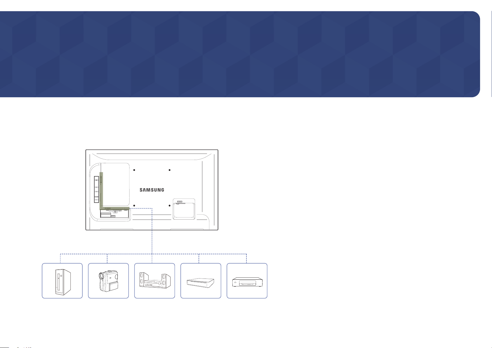
Check the following before you connect this product with other devices.
Devices that can be connected to this product include PCs, camcorders, speakers, set top boxes and DVD/Blu-ray Disc players.
Pre-connection Checkpoints
―
Before connecting a source device, read the user manual provided with it.
The number and locations of ports on source devices may differ from device to
device.
―
Do not connect the power cable until all connections are completed.
Connecting the power cable during connection may damage the product.
―
Connect the sound ports correctly: left = white and right = red.
―
Check the types of ports at the back of the product you want to connect.
41
Page 42
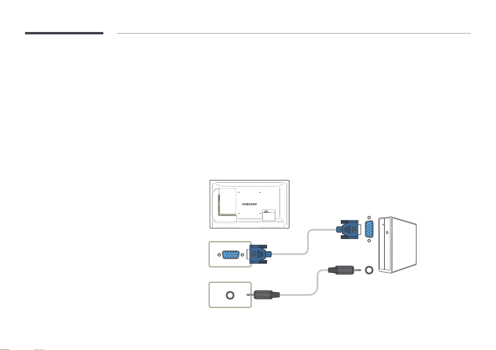
Connecting to a PC
•
Do not connect the power cable before connecting all other cables.
Ensure you connect a source device first before connecting the power cable.
•
A PC can be connected to the product in a variety of ways.
Select a connection method suitable for your PC.
―
Connecting parts may differ in different products.
Connection using the D-SUB cable
(Analog type)
RGB IN
RGB / DVI / HDMI / AV / COMPONENT
/ AUDIO IN
42
Page 43
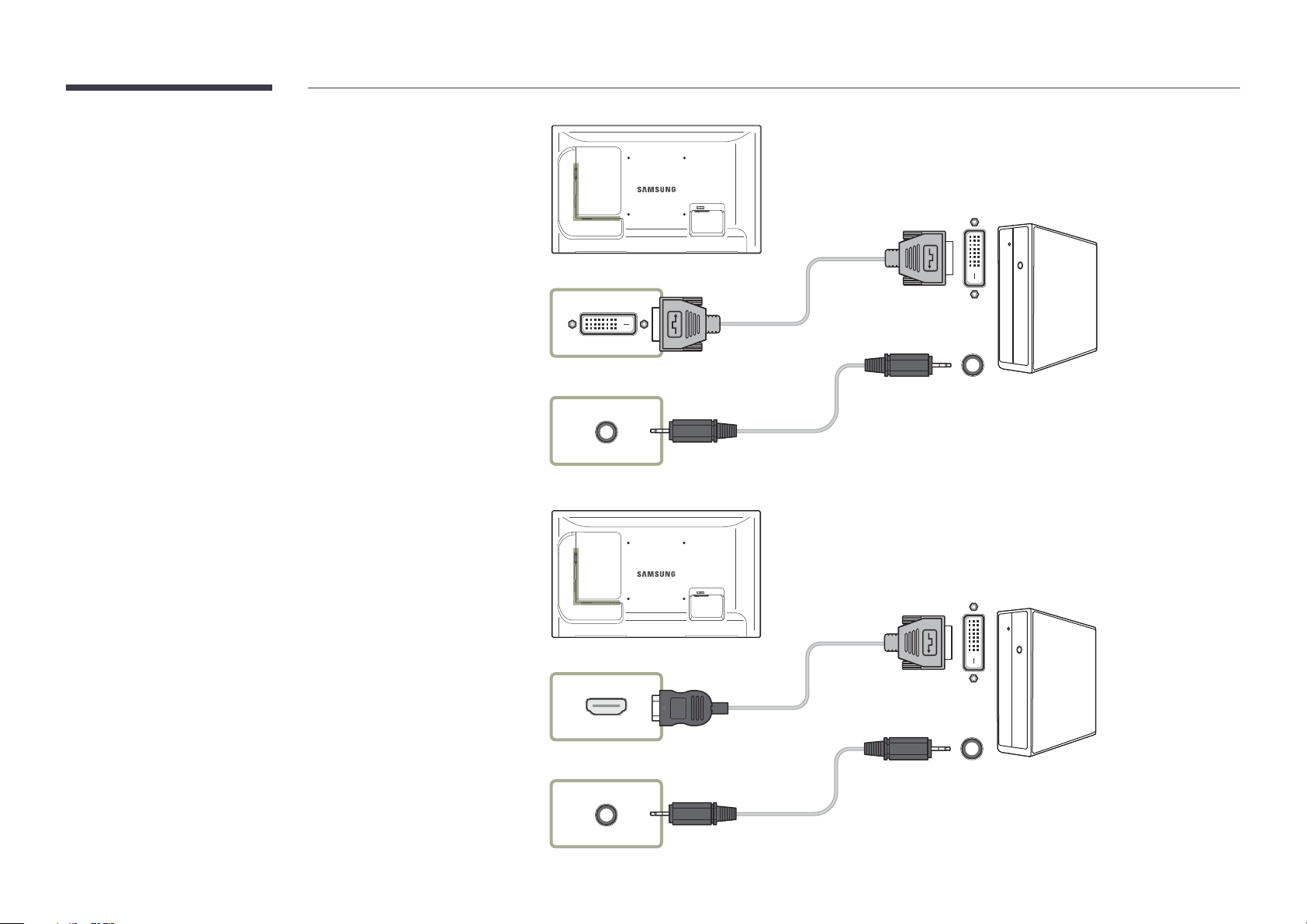
Connection using a DVI cable (Digital type)
DVI IN
RGB / DVI / HDMI / AV / COMPONENT
/ AUDIO IN
Connection Using an HDMI-DVI Cable
―
When you connect a PC to the product using an HDMI-DVI cable, set Edit
Name to DVI PC to access video and audio content stored on the PC.
HDMI IN 1, HDMI IN 2
RGB / DVI / HDMI / AV / COMPONENT
/ AUDIO IN
43
Page 44
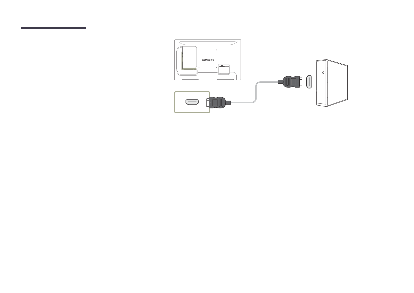
Connection Using an HDMI Cable
HDMI IN 1, HDMI IN 2
44
Page 45
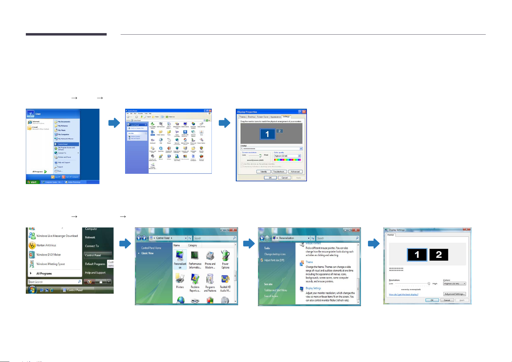
Changing the Resolution
―
Adjust the resolution and refresh rate in Control Panel on your PC to obtain optimum picture quality.
―
The picture quality of TFT-LCDs may degrade if the optimum resolution is not selected.
Changing the Resolution on Windows XP
Go to Control Panel Display Settings, and change the resolution.
Changing the Resolution on Windows Vista
Go to Control Panel Personal Settings Display Settings, and change the resolution.
45
Page 46
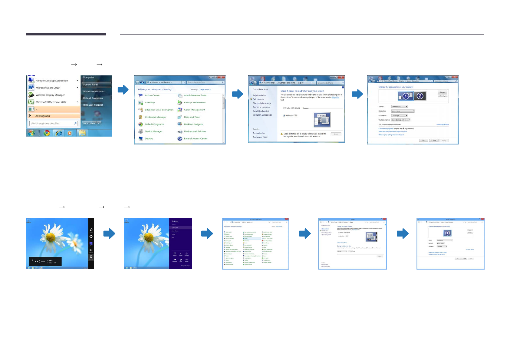
Changing the Resolution on Windows 7
Go to Control Panel Display Screen Resolution, and change the resolution.
Changing the Resolution on Windows 8
Go to Settings Control Panel Display Screen Resolution, and change the resolution.
46
Page 47
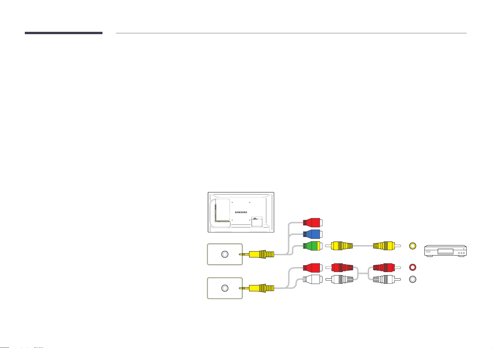
Connecting to a Video Device
•
Do not connect the power cable before connecting all other cables.
Ensure you connect a source device first before connecting the power cable.
•
You can connect a video device to the product using a cable.
―
Connecting parts may differ in different products.
―
Press the SOURCE button on the remote control to change the source.
Connection Using the AV Cable
AV / COMPONENT IN
RGB / DVI / HDMI / AV / COMPONENT
/ AUDIO IN
47
Page 48

Connection Using the component Cable
Connection Using an HDMI-DVI Cable
―
Audio will not be enabled if the product is connected to a video device using
an HDMI-DVI cable. To resolve this, additionally connect an audio cable to the
audio ports on the product and video device.
When you connect a video device to the product using an HDMI-DVI cable, set
Edit Name to DVI Devices to access video and audio content stored on the
video device.
―
Supported resolutions include 1080p (50/60Hz), 720p (50/60Hz), 480p, and
576p.
AV / COMPONENT IN
RGB / DVI / HDMI / AV / COMPONENT
/ AUDIO IN
HDMI IN 1, HDMI IN 2
RGB / DVI / HDMI / AV / COMPONENT
/ AUDIO IN
48
Page 49
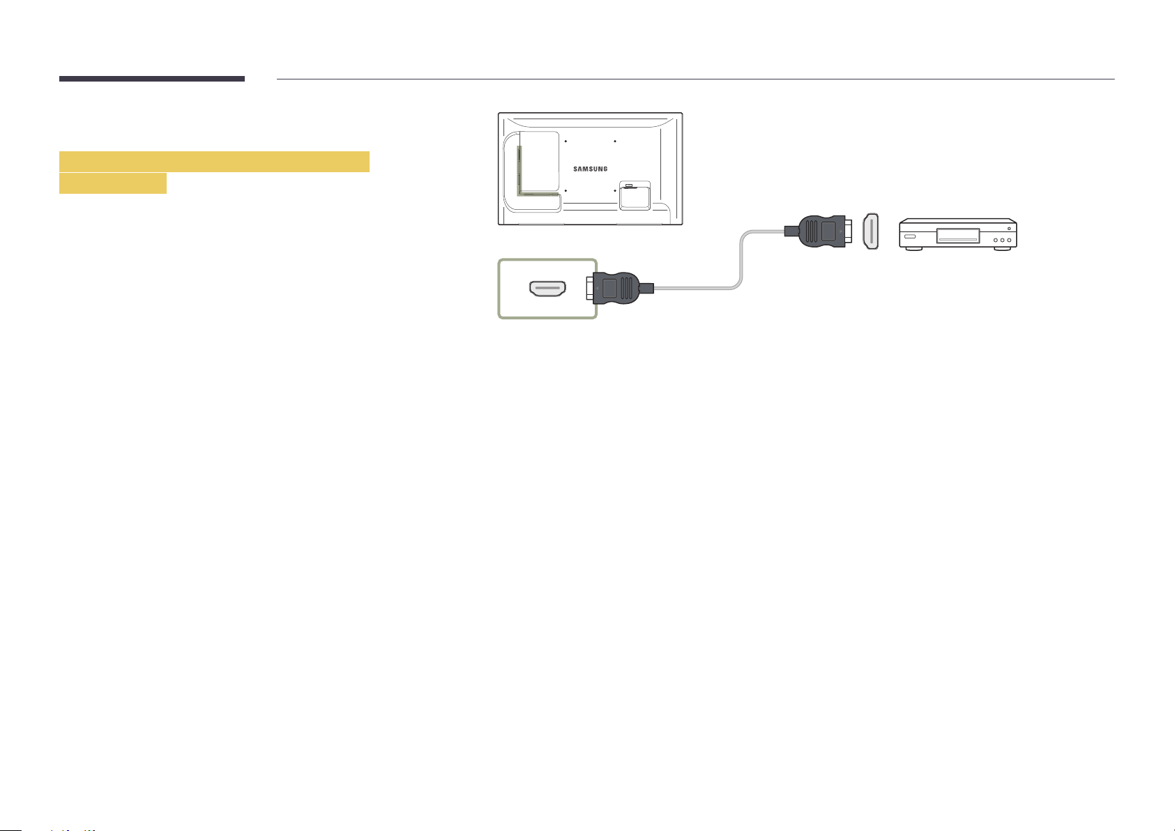
Connection Using an HDMI Cable
Using an HDMI cable or HDMI-DVI Cable
(up to 1080p)
•
For better picture and audio quality, connect to a digital device using an
HDMI cable.
•
An HDMI cable supports digital video and audio signals, and does not
require an audio cable.
-
To connect the product to a digital device that does not support HDMI
output, use an HDMI-DVI and audio cables.
•
The picture may not display normally (if at all) or the audio may not work if
an external device that uses an older version of HDMI mode is connected to
the product. If such a problem occurs, ask the manufacturer of the external
device about the HDMI version and, if out of date, request an upgrade.
•
Be sure to use an HDMI cable with a thickness of 14 mm or less.
•
Be sure to purchase a certified HDMI cable. Otherwise, the picture may not
display or a connection error may occur.
•
A basic high-speed HDMI cable or one with ethernet is recommended.
This product does not support the ethernet function via HDMI.
HDMI IN 1, HDMI IN 2
49
Page 50
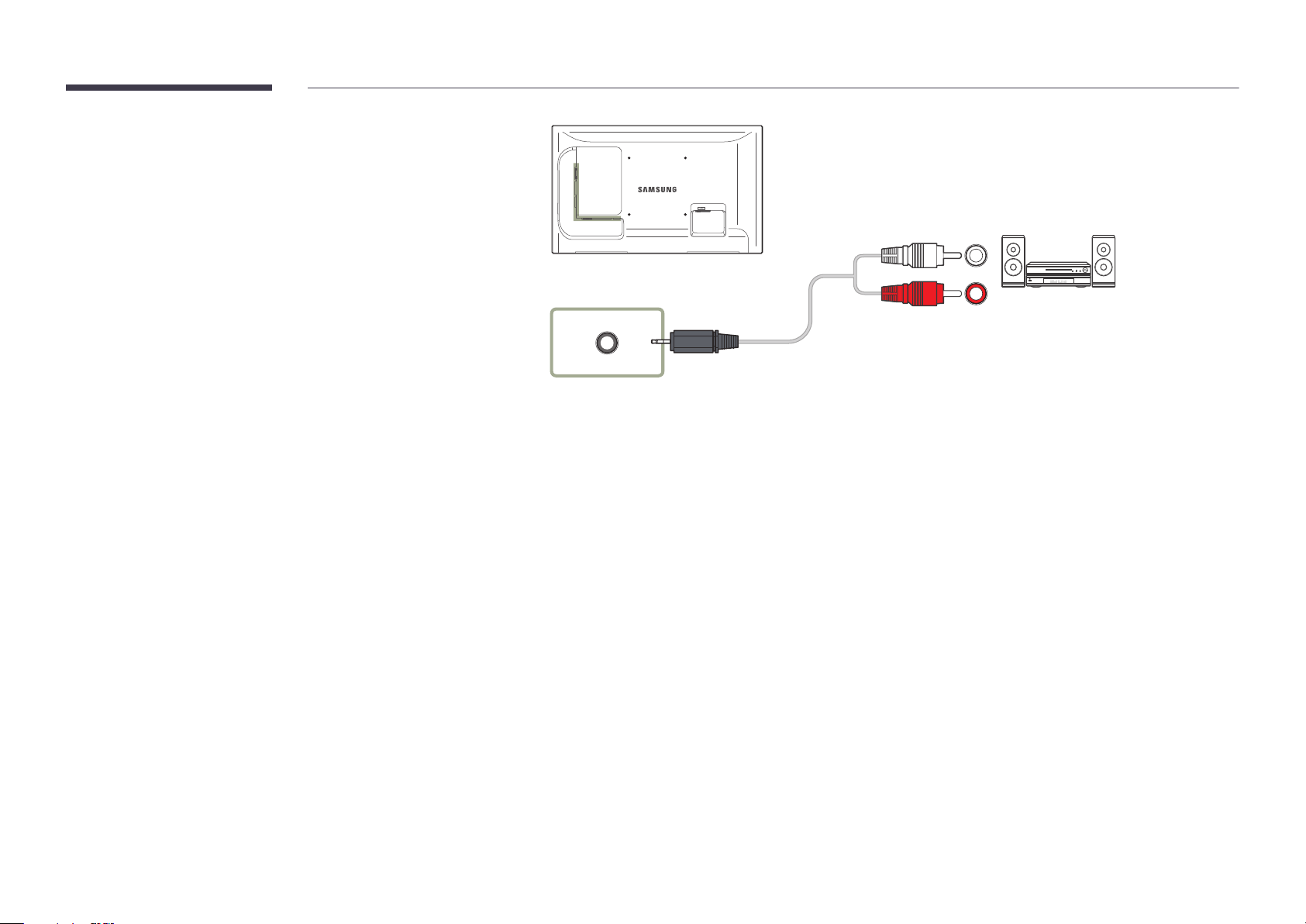
Connecting to an Audio System
―
Connecting parts may differ in different products.
RGB / DVI / HDMI / AV / COMPONENT
/ AUDIO OUT
50
Page 51
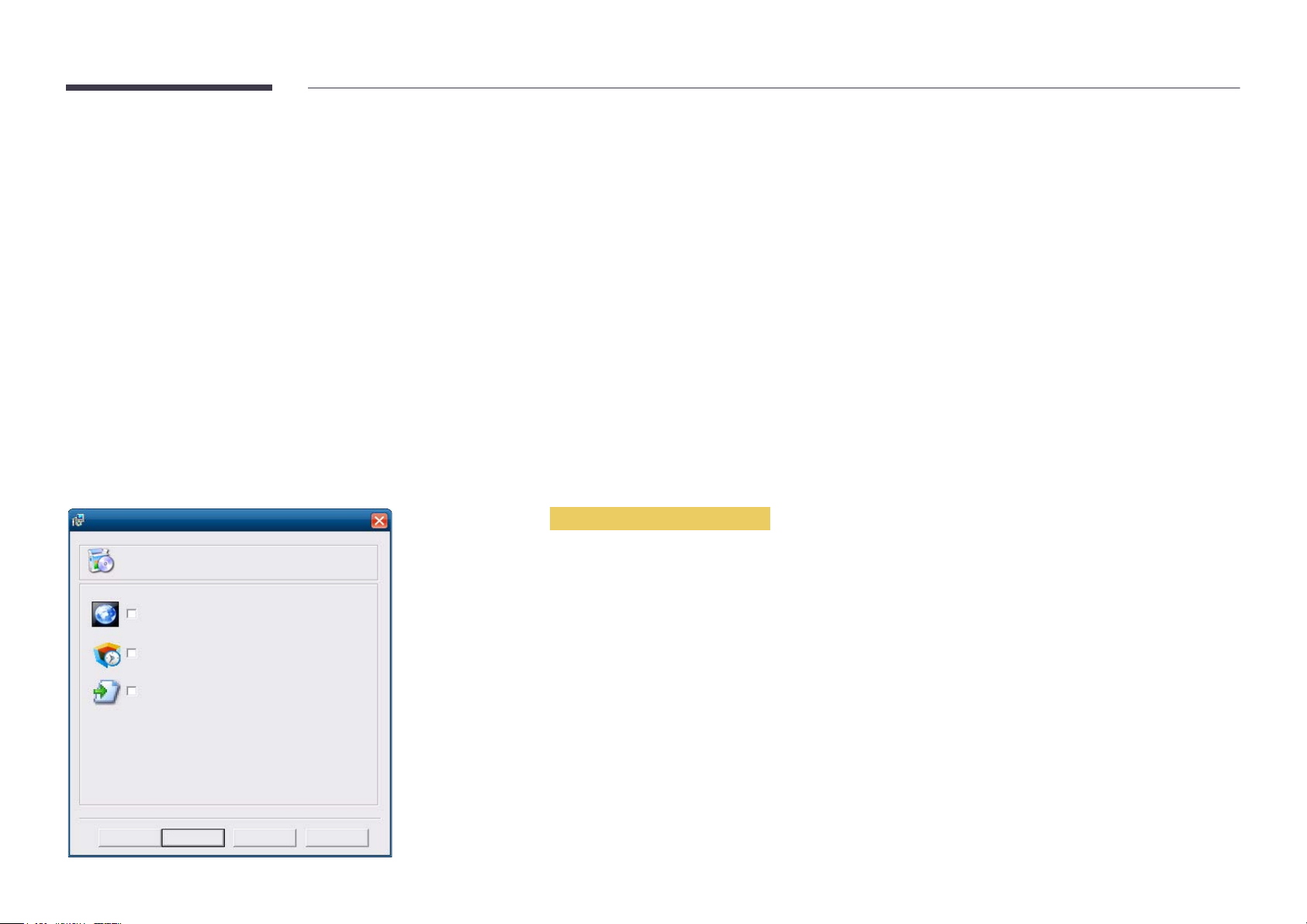
Connecting the network box (Sold separately)
MagicInfo Setup Wizard - v.1.12
Select Application - step 1
MagicInfo Pro (LAN, WAN based version)
MagicInfo-i Premium (Web-based version)
Select Later
< Back(B) Next(N) > Finish Cancel
―
For details on how to connect to a network box, refer to the user's manual provided with the network box upon purchase.
MagicInfo
To use MagicInfo, a network box (sold separately) must be connected to the product.
―
To change the MagicInfo settings, run "MagicinfoSetupWizard" on the desktop.
―
For details on how to use MagicInfo, refer to the DVD provided with the network box.
―
The information in this section is subject to change without notice for quality improvement.
―
If a problem occurs after installing an operating system other than the one provided with the network box, restoring the previous version of the operating system, or
installing software that is not compatible with the operating system provided, you will not be able to benefit from technical support and will be charged a fee for a visit
from a service technician. A product exchange or refund will also not be available.
Entering MagicInfo mode
After installing and connecting the network box (sold separately) to the product, power on the product.
1
Press SOURCE on the remote control, and select MagicInfo.
2
Select the default application you want to run when MagicInfo starts.
3
51
Page 52
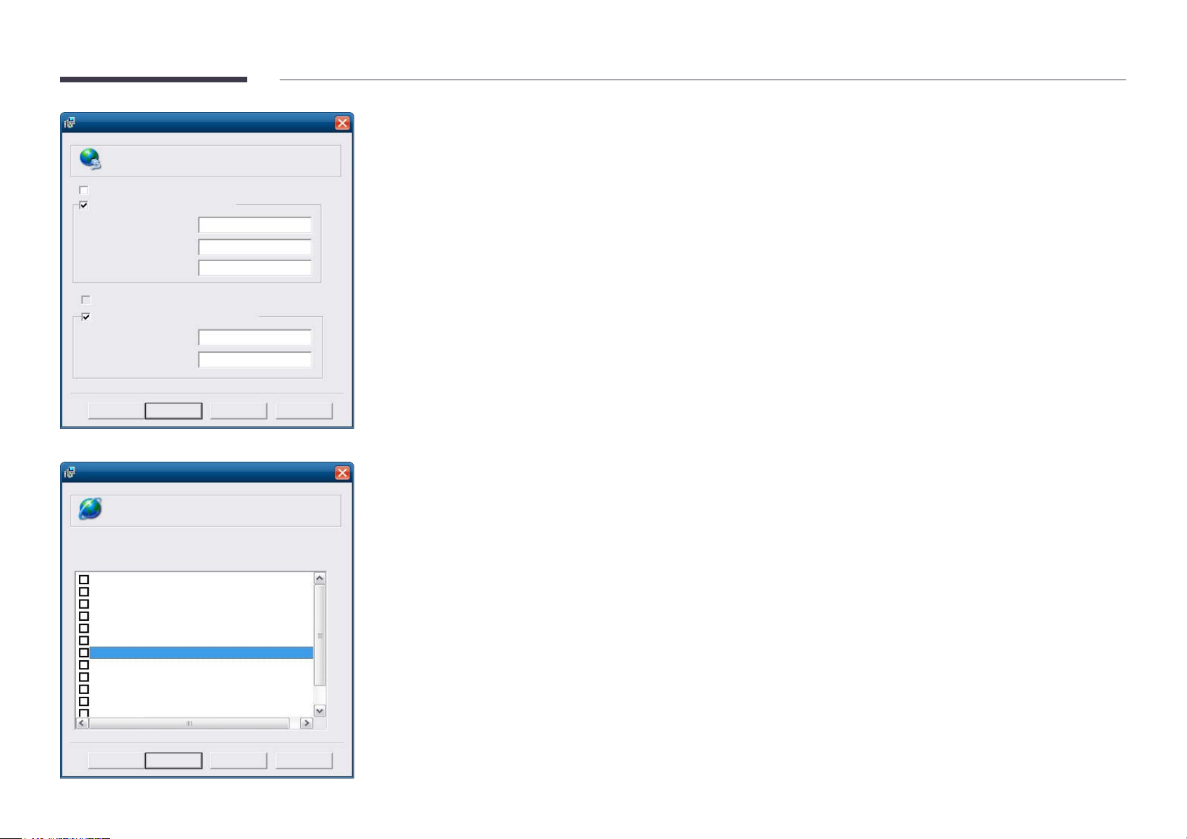
MagicInfo Setup Wizard - v.1.12
Select TCP/IP - step 2
Obtain an IP address automatically
Use the following IP address:
IP address:
Subnet mask:
Default gateway:
192 . 168 . 0 . 102
255 . 255 . 255 . 0
192 . 168 . 0 . 1
Obtain DNS server address automatically
Use the following DNS server address:
Preferred DNS server:
Alternate DNS server:
10 . 44 . 33 . 22
10 . 33 . 22 . 11
< Back(B) Next(N) > Finish Cancel
Enter the IP information.
MagicInfo Setup Wizard - v.1.12
Select Language -step 3
Select the language you want to install on the system for menus and
dialogs.
Current Language : Engilsh
German
English
French
Italian
Chinese [Traditional]
Japanese
Korean
Russian
Swedish
Turkish
Chinese [Simplified]
Portuguese
< Back(B) Next(N) > Finish Cancel
4
Select a language. (The default language is English.)
5
52
Page 53
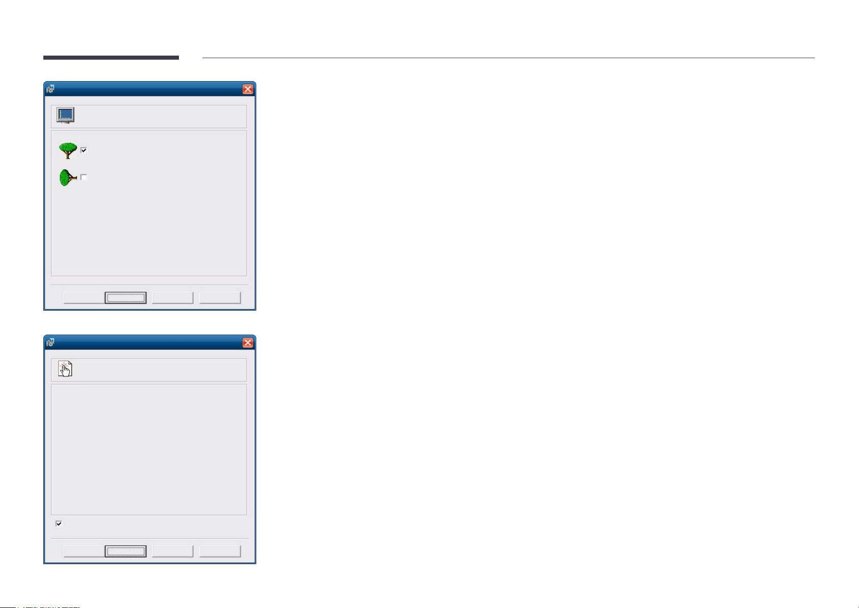
MagicInfo Setup Wizard - v.1.12
Select Screen Type - step 4
Landscape
Portrait
< Back(B) Next(N) > Finish Cancel
MagicInfo Setup Wizard - v.1.12
Setup Information
1. Application : MagicInfo Pro [LAN,WAN based version\
2. Internet Protocol [TCP/IP]
IP : 192.168.0.102
3. Language : English
4. Screen Type : Landscape
Do not show again
< Back(B) Apply Finish Cancel
Select a display mode.
6
Double-check the settings you have just configured.
7
―
If the execution icon does not appear, double-click the MagicInfo icon on the desktop. The icon will appear at the bottom
right of the screen.
53
Page 54
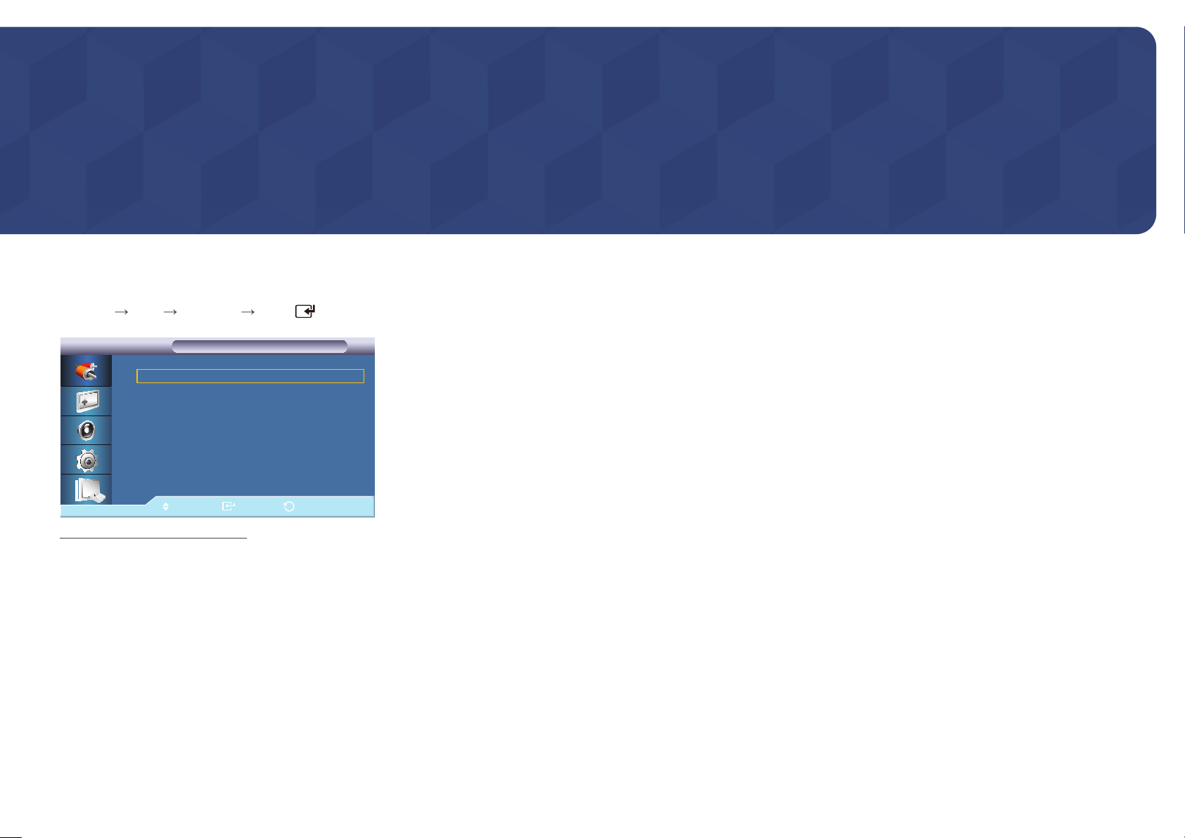
Chapter 04
Input
Source List
MENU
-
Input Source List ENTER
Source List
Source List
PC :----
DVI :---AV :---Component :---HDMI1 :---HDMI2 :---MagicInfo :---TV :----
Move Enter Return
The displayed image may differ depending on the model.
Use to select PC, HDMI or other external input sources connected to the LCD Display.
Use to select the screen of your choice.
PC
1
DVI
2
AV
3
Component
4
HDMI1
5
HDMI2
6
This is deactivated when a network box is installed.
MagicInfo
7
Activated when a network box is connected.
TV
8
54
Page 55
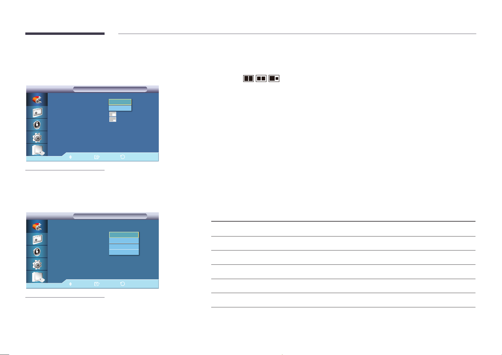
PIP
PIP
PIP
PIP
PIP :On ►
Source :PC
Size :
Position :
Transparency :Medium
Move Enter Return
-
The displayed image may differ depending on the model.
Off
On
Turns the PIP Screen Off/On.
•
Off / On
―
PIP turns off when the LCD Display is switched to an external source.
―
If you select , , in Size, Position and Transparency will not be activated.
―
The PIP function is not available when Video Wall is On.
―
When external AV devices such as VCRs or DVDs are connected to the LCD Display , PIP allows you to watch video from
those devices in a small window super-imposed on the PC Video signal.
Source
PIP
PIP
PIP :On
Source :HDMI 1
Size :AV
Position :----
Transparency :투명하게
Move Enter Return
-
The displayed image may differ depending on the model.
DVI
AV
HDMI1
HDMI2
Selects the input source for the PIP.
Primary Source Secondary Source
PC DVI, AV, HDMI1, HDMI2
DVI PC
AV PC
HDMI1 PC
HDMI2 PC
PIM PC, AV , Component
―
PIP is disabled if the primary screen does not receive a signal.
55
Page 56
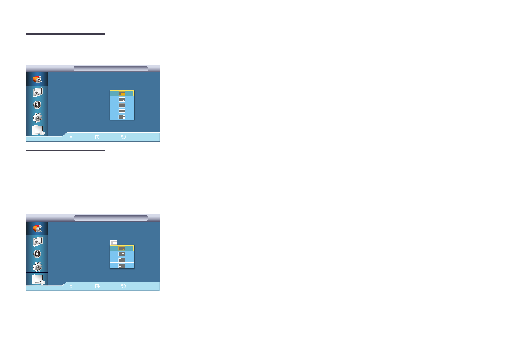
Size
PIP
PIP
PIP :On
Source :HDMI 1
Size :----
Position :----
Transparency :투명하게
Move Enter Return
-
The displayed image may differ depending on the model.
Changes the Size of the PIP window.
―
Picture > Size will be changed to 16:9when PIP is On.
Position
PIP
PIP
PIP :On
Source :HDMI 1
Size :----
Position :----
Transparency :투명하게
Move Enter Return
-
The displayed image may differ depending on the model.
Changes the Position of the PIP window.
56
Page 57
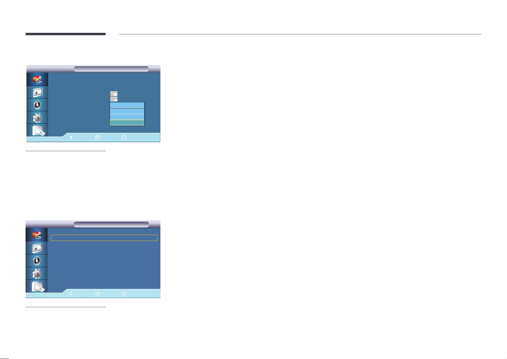
Transparency
PIP
PIP
PIP :On
Source :HDMI 1
Size :---Position :----
Transparency :투명하게
Move Enter Return
-
The displayed image may differ depending on the model.
High
Medium
Low
Opaque
Adjusts the Transparency of PIP windows.
•
High
•
Medium
•
Low
•
Opaque
Edit Name
Edit Name
Edit Name
PC :---- ▶
DVI :---- ▶
AV :---- ▶
Component :---- ▶
HDMI1 :---- ▶
HDMI2 :---- ▶
Move Enter Return
-
The displayed image may differ depending on the model.
Name the input device connected to the input jacks to make your input source selection easier.
VCR / DVD / Cable STB / HD STB / Satellite STB / AV Receiver / DVD Receiver / Game / Camcorder / DVD Combo / DHR /
PC / DVI PC / DVI Devices
―
The displayed devices differ depending on the external input mode.
When connecting a PC to the HDMI terminal, set Edit Name to PC. In other cases, set Edit Name to AV. However, since
640x480, 720p (1280x720), and 1080p (1920x1080) are common signals for AV and PC, make sure to set the Edit Name in
accordance with the input signal.
―
The Picture menu changes depending on the input signal and Edit Name.
When using a HDMI-DVI cable connection (which does not support audio and video at the same time), the audio port
should be connected via a separate audio cable.
When a PC is connected, set Edit Name to DVI PC to enjoy the video and audio from the connected PC.
When an AV device is connected, set Edit Name to DVI Devices to enjoy the video and audio from the connected AV
device.
57
Page 58
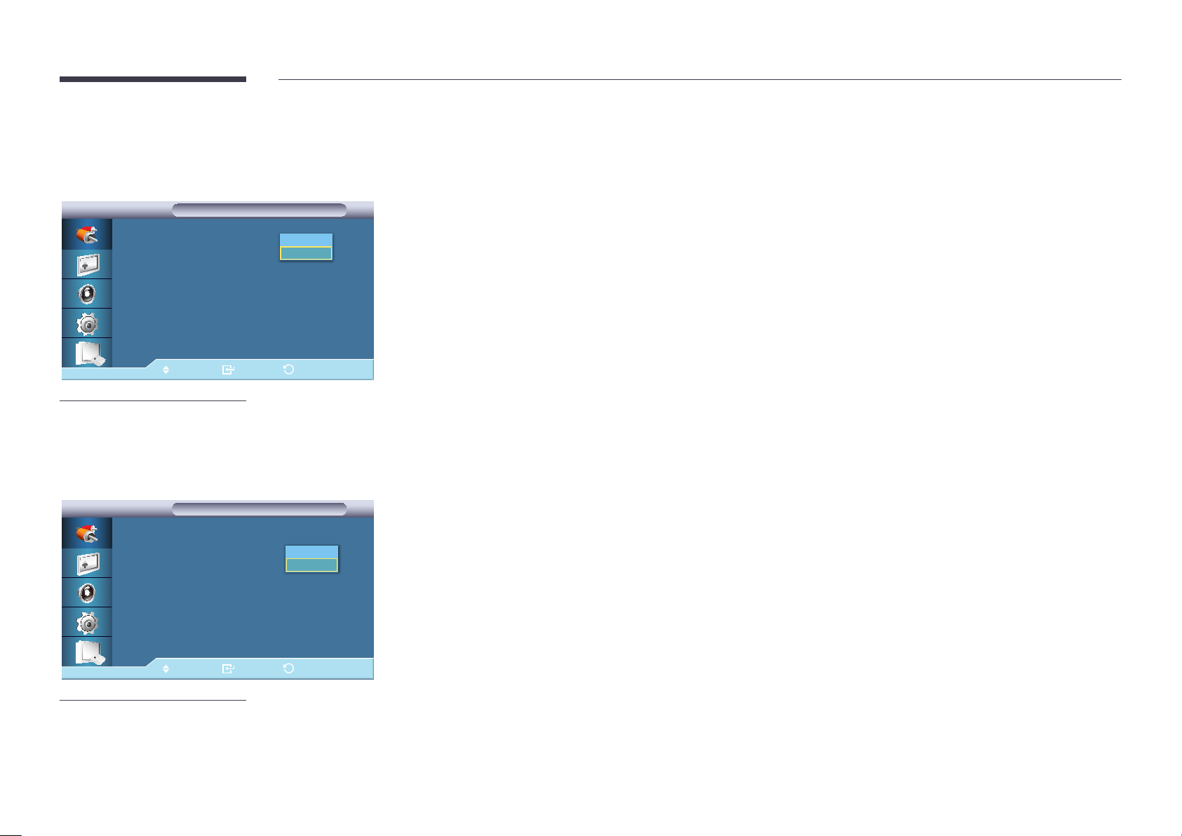
Source AutoSwitch Settings
Source AutoSwitch
Source AutoSwitch Settings
Source AutoSwitch Settings
: On
Source AutoSwitch
Primary Source Recovery
Primary Source
Secondary Source
Move Enter Return
-
The displayed image may differ depending on the model.
-
Source AutoSwitch Settings is disabled if PIP is set to On.
Off
On
: On
: DVI
: PC
When the Source AutoSwitch is On, the display video source will automatically be searched for active video.
The Primary Source selection will be activated, if the current video source is not recognized.
Secondary Source selection will become active, if no primary video source is available. If the primary or secondary source is
not recognized, the display will search again, if no active video is found the display will show the no-input-signal message.
When the Primary Source selection is set to All, the display will search all the video source inputs twice in sequence looking
for an active video source, returning back to the first video source in the sequence if no video is found.
•
Off / On
―
Source AutoSwitch selection and PIP function: If the Source AutoSwitch selection is set to On, the PIP function will not
work, the Source AutoSwitch selection must be set to Off, for the PIP feature to work.
―
When the Source AutoSwitch selection is On, and or the Primary Source Recovery is On, the display power saving mode
becomes inactive.
―
When Primary Source Recovery is On, only the Primary Source and Secondary Source selection are available and they
are interchangeable and selectable at will. Refer to PIP > Source for compatible signals for each primary input source.
Primary Source Recovery
Source AutoSwitch Settings
Source AutoSwitch Settings
Source AutoSwitch
Primary Source Recovery
Primary Source
Secondary Source
Move Enter Return
-
The displayed image may differ depending on the model.
: On
: On
:
: PC
Off
On
When Primary Source Recovery is On, only the Primary Source and Secondary Source video source selection will be
searched for active video.
The Primary Source will be selected if active video is found, if no video is found, the Secondary Source will be selected, if no
video is found in Secondary Source again, the no-input-signal is displayed.
•
Off / On
58
Page 59
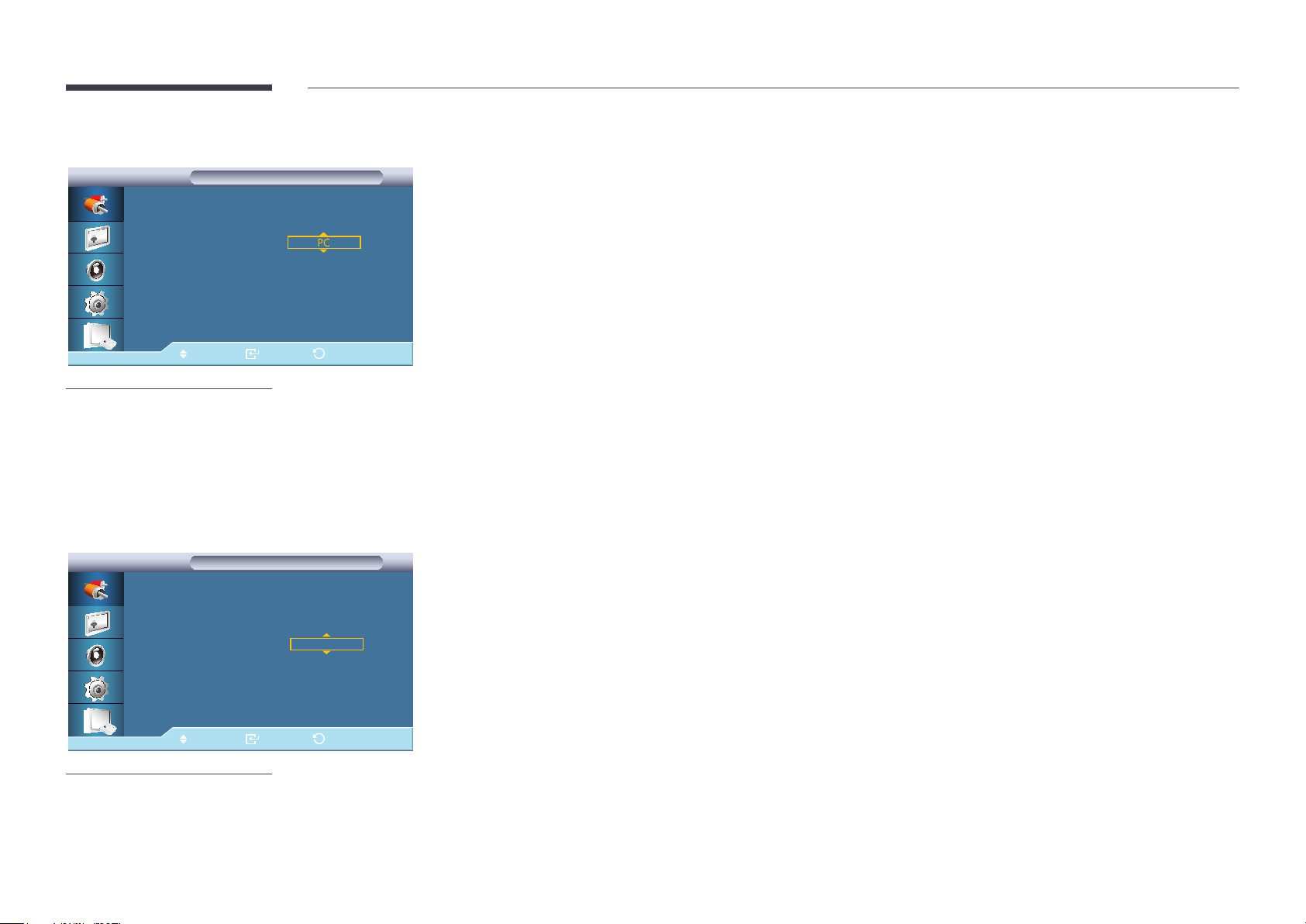
Primary Source
Source AutoSwitch Settings
Source AutoSwitch Settings
Specify Primary Source for the automatic input source.
Source AutoSwitch
Primary Source Recovery
Primary Source
Secondary Source
Move
-
The displayed image may differ depending on the model.
Enter Return
: On
: On
:
: DVI
Secondary Source
Source AutoSwitch Settings
Source AutoSwitch Settings
Source AutoSwitch
Primary Source Recovery
Primary Source
Secondary Source
: PC
:
DVI
Specify Secondary Source for the automatic input source.
: On
: On
Move Enter Return
-
The displayed image may differ depending on the model.
59
Page 60
Chapter 05
Picture
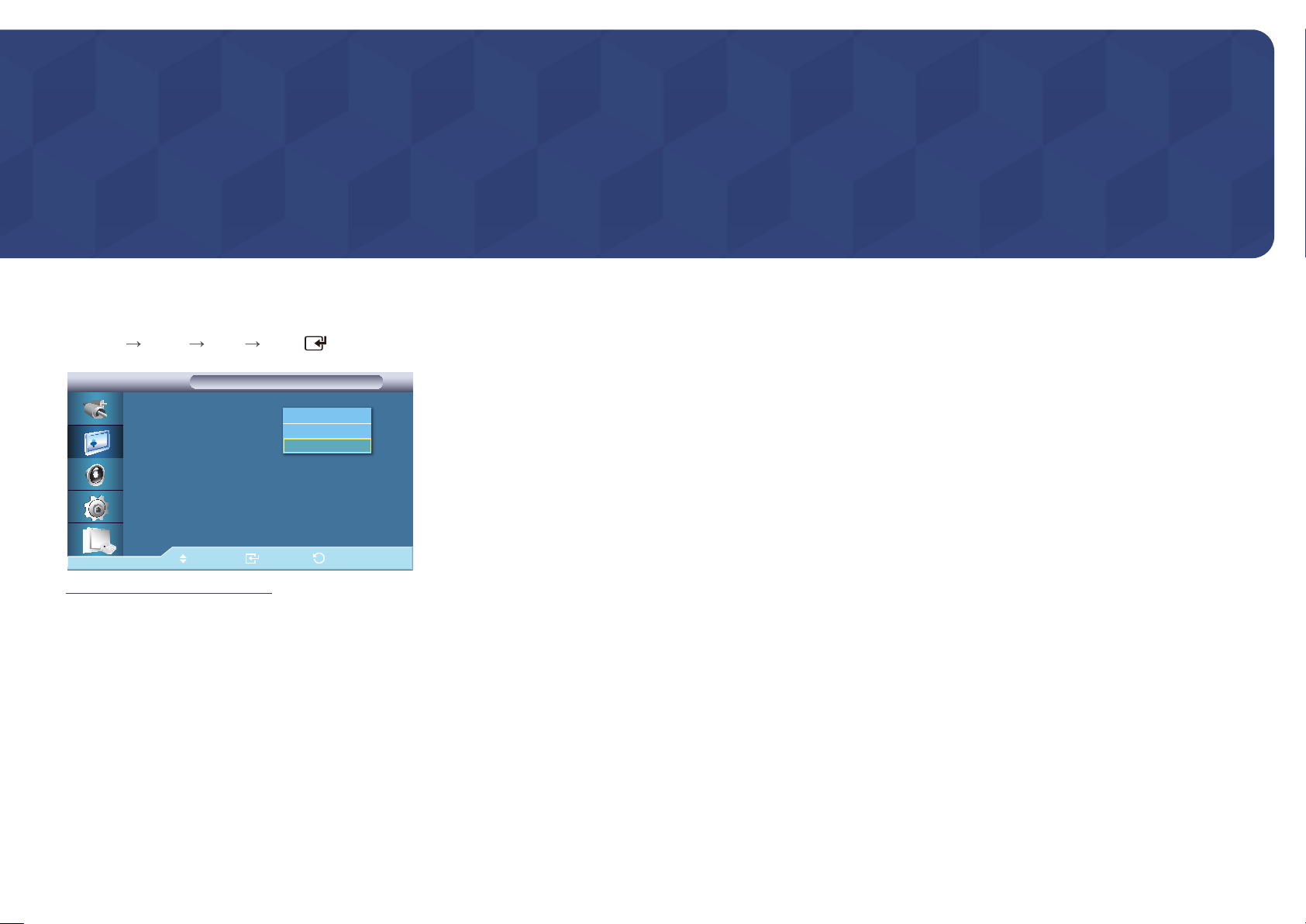
PC / DVI / MagicInfo Mode
Mode
MENU
-
Picture Mode ENTER
Picture
Picture
Mode :사용자 조정
Custom
Color Tone :----
Color Control
Color Temp.
Image Lock
Auto Adjustment
▶
More
Move Enter Return
The displayed image may differ depending on the model.
Information
Advertisement
Custom
The LCD Display has four automatic picture settings ("Information", "Advertisement" and "Custom") that are preset at the
factory.
•
Information
Recommended for communicating exact information (e.g. public information).
•
Advertisement
Recommended for displaying advertisements (e.g. videos or indoor or outdoor ads).
•
Custom
―
Not available when Dynamic Contrast is set to On.
60
Page 61
Custom
Custom
Custom
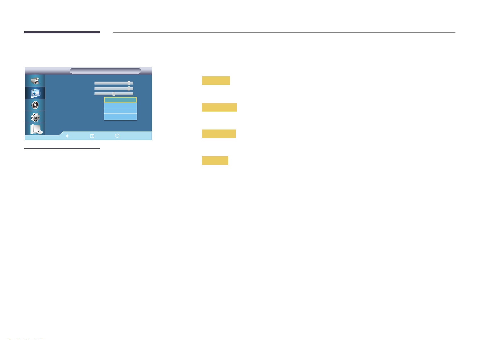
By using the on-screen menus, the contrast and brightness can be changed to your personal preference.
―
By adjusting the picture using the Custom function, Mode will change to Custom mode.
―
Not available when Dynamic Contrast is set to On.
Contrast
Brightness
Sharpness
Gamma :
Move Enter Return
-
The displayed image may differ depending on the model.
Natural
Mode1
Mode2
Mode3
90
90
50
Contrast
Adjusts the Contrast.
Brightness
Adjusts the Brightness.
Sharpness
Adjusts the Sharpness.
Gamma
Adjust the mid-range brightness (Gamma) for the picture.
•
Natural
•
Mode1
Sets the picture brighter than Natural.
•
Mode2
Sets the picture darker than Mode1.
•
Mode3
Increases the contrast between dark and bright colors.
61
Page 62
Color Tone
Picture
Picture
Mode : Custom
Custom
Color Tone : 16:9
Color Control
Color Temp. : 16:9
Image Lock : 동작
Auto Adjustment : 일반
▶
More
Move Enter Return
-
The displayed image may differ depending on the model.
Off
Cool
Normal
Warm
Custom
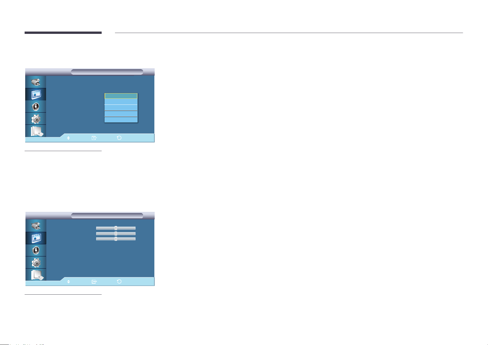
The Color tones can be changed.
―
Not available when Dynamic Contrast is set to On.
•
Off / Cool / Normal / Warm / Custom
―
If you set the Color Tone to Cool, Normal, Warm, or Custom, the Color Temp. function is disabled.
―
If you set the Color Tone to Off, the Color Control function is disabled
Color Control
Color Control
Color Control
Red
Green
Blue
Move Enter Return
-
The displayed image may differ depending on the model.
50
50
50
Adjusts individual Red, Green, Blue Color balance.
―
Not available when Dynamic Contrast is set to On.
•
Red / Green / Blue
62
Page 63
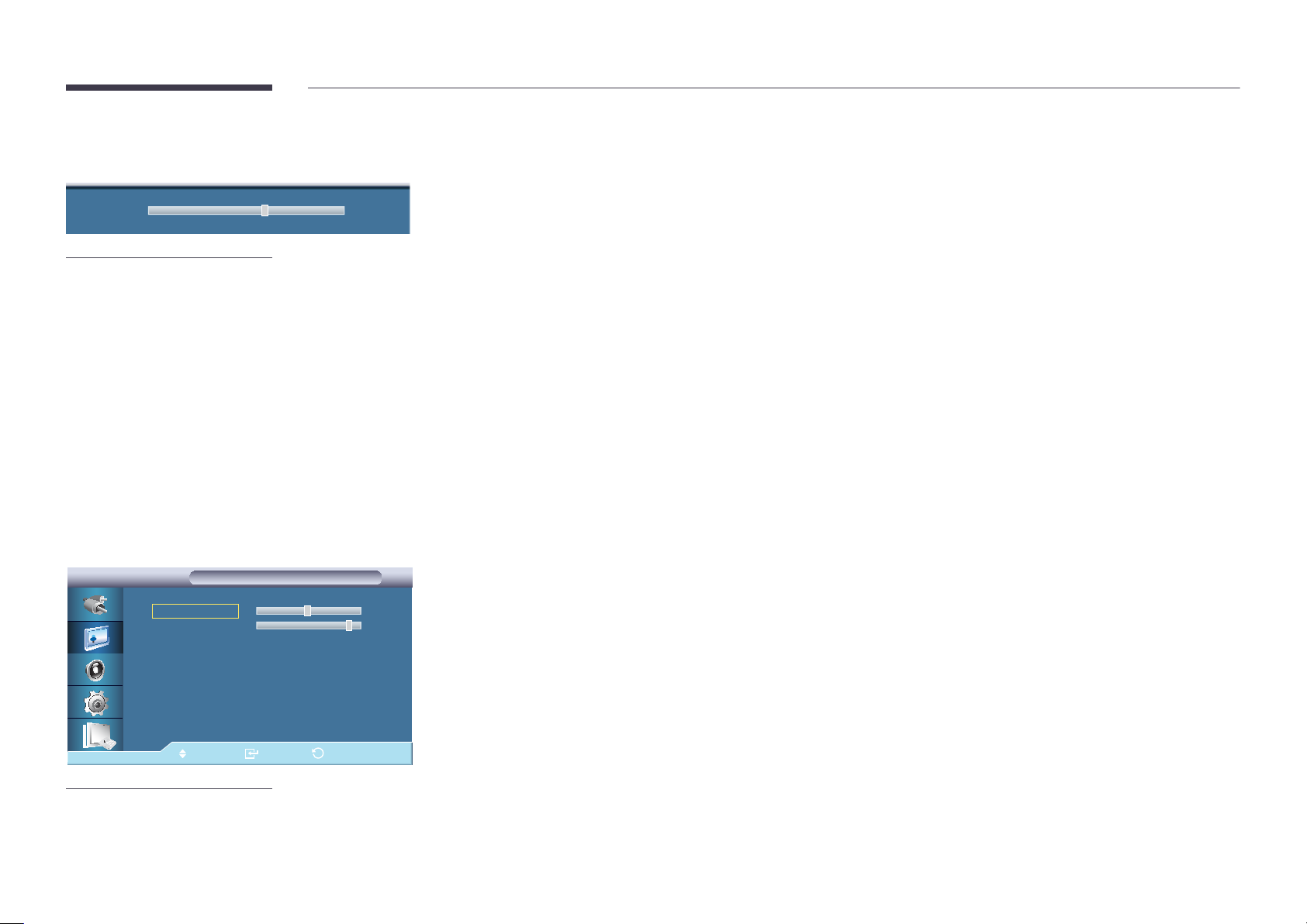
Color Temp.
Color Temp. 10000K
-
The displayed image may differ depending on the model.
Color Temp. is a measure of the 'warmth' of the image Colors.
―
This function is enabled when Mode is set to Custom, and Dynamic Contrast and Color Tone are Off.
Image Lock
Image Lock
Image Lock
Coarse
Fine
Position
Move Enter Return
-
The displayed image may differ depending on the model.
-
Available in PC mode only.
2200
55
▶
Image Lock is used to fine-tune and get the best image by removing noise that creates unstable images with jitters and
shakiness. If satisfactory results are not obtained using the Fine adjustment, use the Coarse adjustment and then use Fine
again.
•
Coarse
Removes noise such as vertical stripes. Coarse adjustment may move the screen image area. You may relocate it to the
Center using the horizontal control menu.
•
Fine
Removes noise such as horizontal stripes. If the noise persists even after Fine tuning, repeat it after adjusting the
frequency (clock speed).
•
Position
Adjusts the screen location horizontally and vertically.
63
Page 64
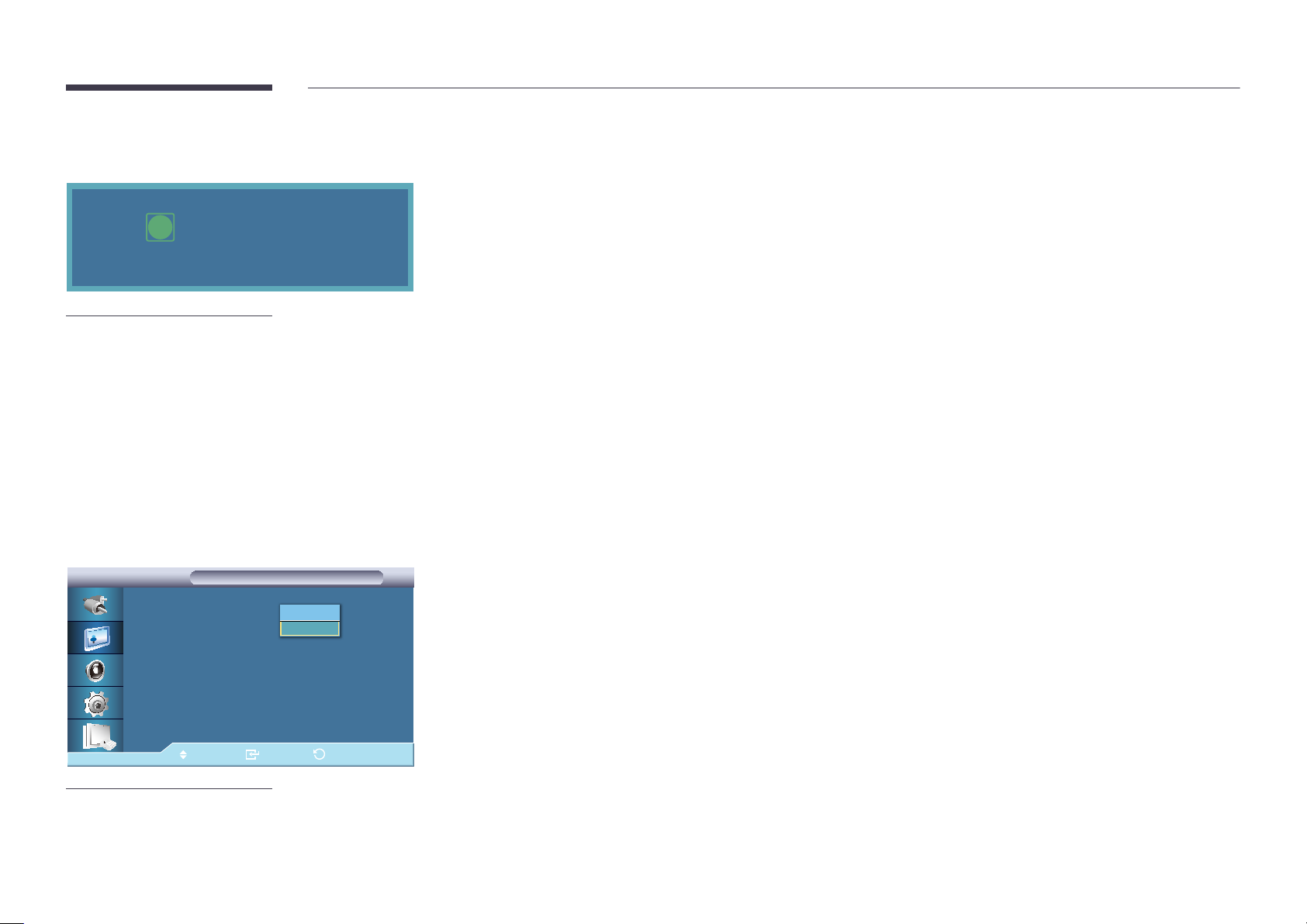
Auto Adjustment
The values of Fine, Coarse, Position are adjusted automatically.
By changing the resolution in the control panel, the auto function is performed.
i
Auto Adjustment
Please wait.
-
The displayed image may differ depending on the model.
-
Available in PC mode only.
Signal Balance
Signal Balance
Signal Balance
Signal Balance : 사용자 조정
Signal Control
Off
On
Signal Balance
Selects either On or Off with the signal balance.
Signal Control
―
Available when Signal Control is set to On.
•
R-Gain / G-Gain / B-Gain / R-Offset / G-Offset / B-Offset
Move Enter Return
-
The displayed image may differ depending on the model.
64
Page 65
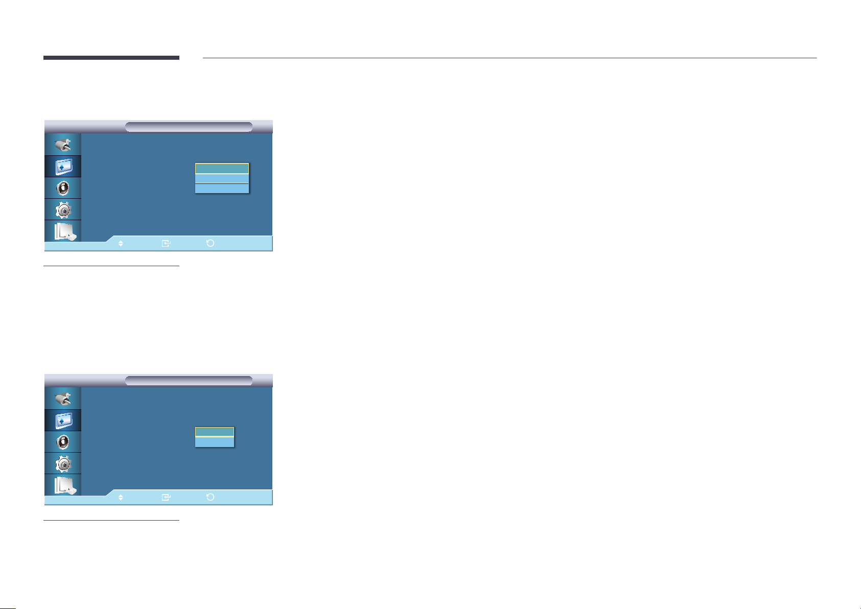
Size
Picture
Picture
▶
More
Signal Balance
Size :
HDMI Black Level : 일반
PIP Picture
Dynamic Contrast : Off
Lamp Control : 100
Brightness Sensor
Picture Reset
Move Enter Return
-
The displayed image may differ depending on the model.
16:9
4:3
Original Ratio
The Size can be switched.
•
16:9 / 4:3 / Original Ratio
HDMI Black Level
Picture
Picture
▶
More
Signal Balance
Size : 16:9
HDMI Black Level :
PIP Picture
Dynamic Contrast : Off
Lamp Control : 100
Brightness Sensor
Picture Reset
Move Enter Return
-
The displayed image may differ depending on the model.
Normal
Low
When a DVD or set-top box is connected to your product via HDMI or DVI port, it may cause a degradation in the screen
quality, such as an increase in the black level, a low contrast, or discoloration, etc., depending on the external device connected.
In this case, adjust the screen quality of your product by configuring the HDMI Black Level.
•
Normal / Low
65
Page 66
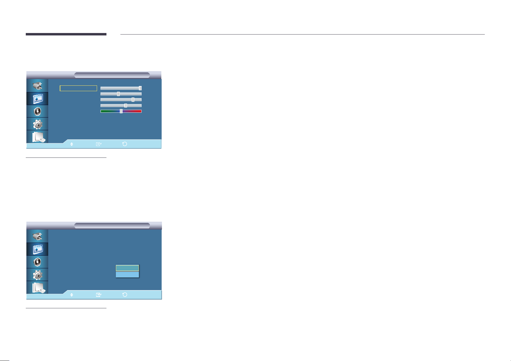
PIP Picture
PIP Picture
PIP Picture
Contrast
Brightness
Sharpness
Color
Tint G 50 R
Move Enter Return
-
The displayed image may differ depending on the model.
100
45
76
60
50
Adjusts the PIP Screen Settings.
―
Available Modes: PIP On
•
Contrast
Adjusts the Contrast of the PIP window on the screen.
•
Brightness
Adjusts the Brightness of the PIP window on the screen.
•
Sharpness
Adjusts the Sharpness of the PIP window on the screen.
•
Color
Adjusts the Color of the PIP window on the screen.
―
PIP input only operates in AV, HDMI1, or HDMI2 mode.
•
Tint
Adds a natural tone to the PIP window.
―
PIP input only operates in AV, HDMI1, or HDMI2 mode.
Dynamic Contrast
Picture
Picture
▶
More
Signal Balance
Size : 16:9
HDMI Black Level : Normal
PIP Picture
Dynamic Contrast : 해제
Lamp Control : 100
Brightness Sensor
Picture Reset
Move Enter Return
-
The displayed image may differ depending on the model.
Off
On
Dynamic Contrast automatically detects the distribution of the visual signal and adjusts to create an optimum contrast.
•
Off / On
―
This function is disabled when PIP or Energy Saving is On.
66
Page 67
Lamp Control
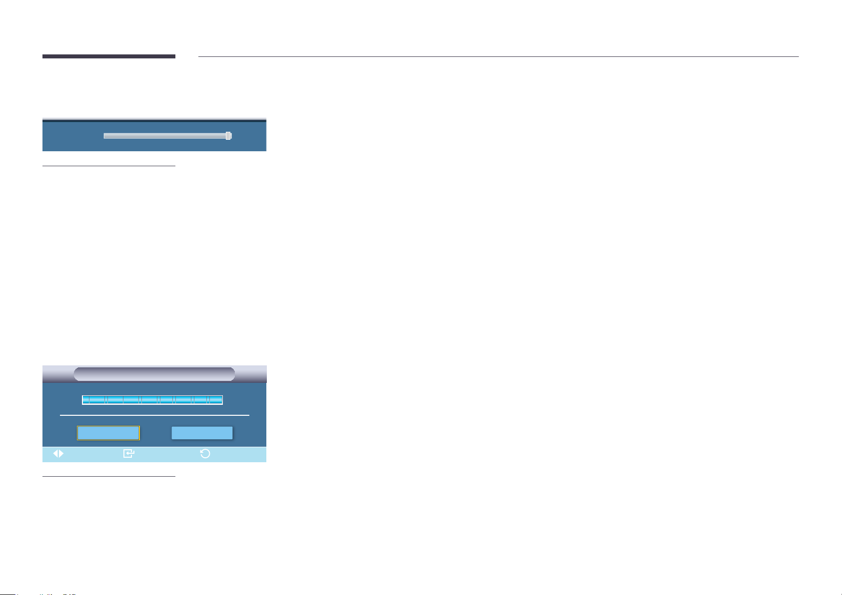
Lamp Control 100
-
The displayed image may differ depending on the model.
Adjusts the inverter lamp in order to reduce energy consumption.
―
Not available when Dynamic Contrast is set to On.
Brightness Sensor
Brightness Sensor
Brightness Sensor
OnOff
Move Enter Return
-
The displayed image may differ depending on the model.
Brightness Sensor detects the ambient light intensity so that the picture brightness can automatically be adjusted.
•
Off / On
67
Page 68

Picture Reset
Reset the screen settings.
i
-
The displayed image may differ depending on the model.
Reset picture settings?
Yes No
68
Page 69
Chapter 06
Picture
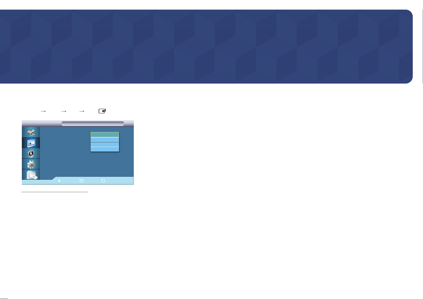
AV / HDMI / TV / Component Mode
Mode
MENU
-
Picture Mode ENTER
Picture
Picture
Mode : 16:9
Custom
Color Tone : 16:9
Color Temp.
Size : 16:9
Digital NR : On
HDMI Black Level : Normal
▶
More
Move Enter Return
The displayed image may differ depending on the model.
Dynamic
Standard
Movie
Custom
The LCD Display has four automatic picture settings ("Dynamic", " Standard", "Movie" and "Custom") that are preset at the
factory.
•
Dynamic
•
Standard
•
Movie
•
Custom
―
Not available when Dynamic Contrast is set to On.
69
Page 70
Custom
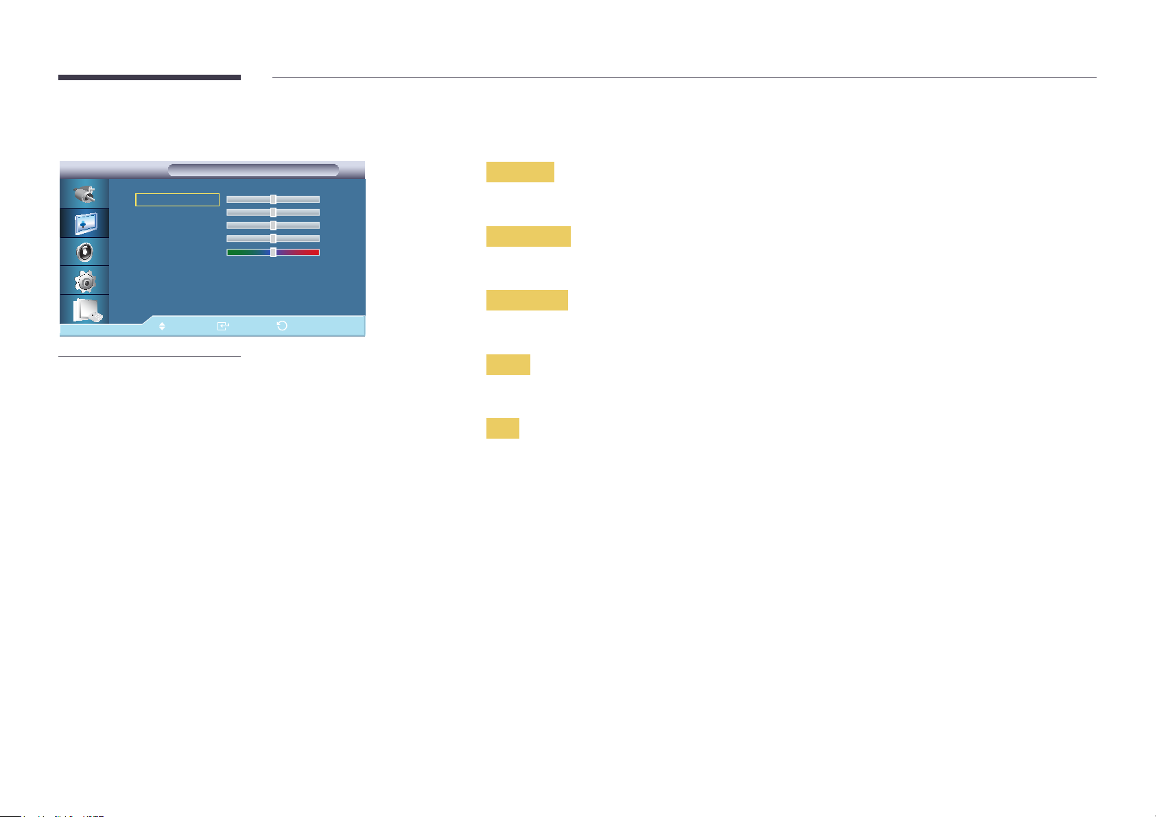
Custom
Custom
By using the on-screen menus, the contrast and brightness can be changed to your personal preference.
―
Not available when Dynamic Contrast is set to On.
Contrast
Contrast
Brightness
Sharpness
Color
Tint G 50 R
Move Enter Return
-
The displayed image may differ depending on the model.
50
50
50
50
50
Adjusts the Contrast.
Brightness
Adjusts the Brightness.
Sharpness
Adjusts the picture Sharpness.
Color
Adjusts the picture Color.
Tint
Adds a natural tone to the display.
―
The Tint slider is only displayed when input source is AV, Component, HDMI1 or HDMI2.
70
Page 71
Color Tone
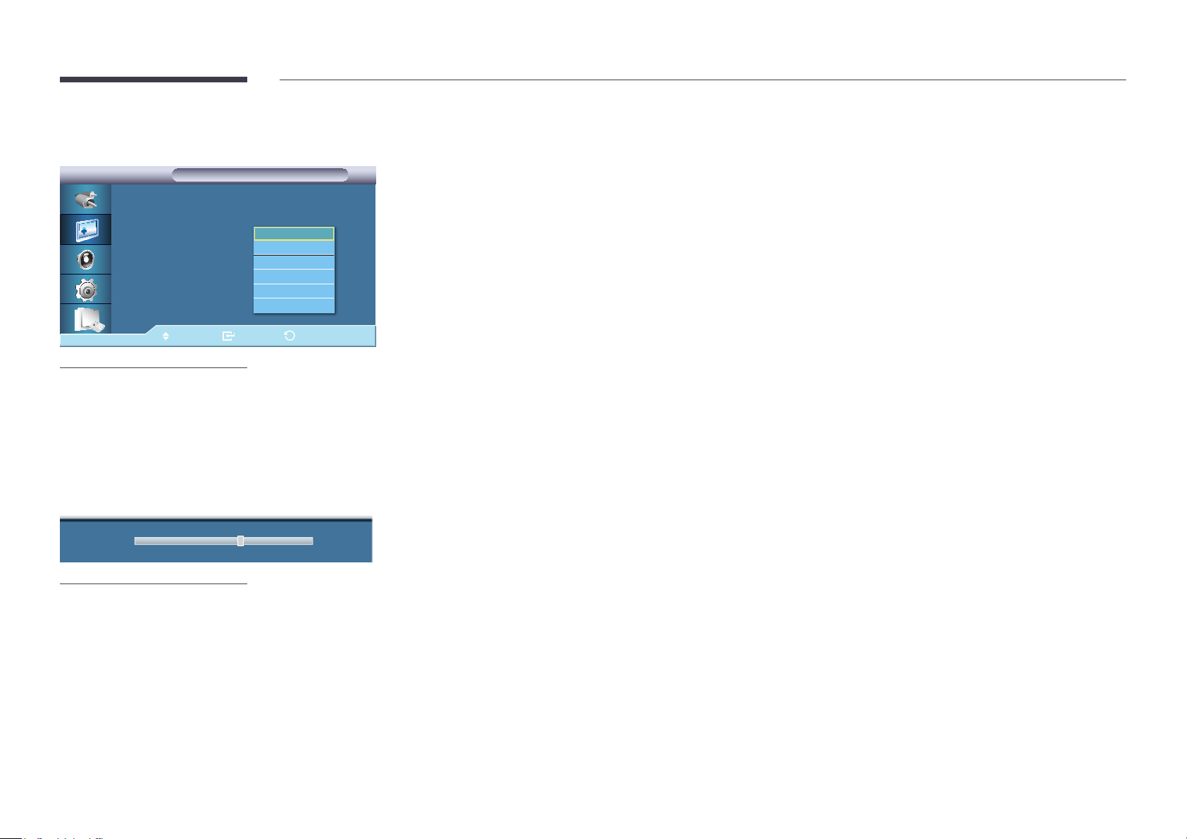
Picture
Picture
Mode : Custom
Custom
Color Tone : 16:9
Color Temp.
Size : 16:9
Digital NR : 동작
HDMI Black Level : 일반
▶
More
Move Enter Return
-
The displayed image may differ depending on the model.
Off
Cool2
Cool1
Normal
Warm1
Warm2
The Color tones can be changed. The individual Color components are also user adjustable.
―
Not available when Dynamic Contrast is set to On.
•
Off / Cool2 / Cool1 / Normal / Warm1 / Warm2
―
If you set the Color Tone to Cool2, Cool1, Normal, Warm1, or Warm2, the Color Temp. function is disabled.
―
Changing a setting in the Color Tone menu will switch the screen mode to Custom.
Color Temp.
Color Temp. 10000K
-
The displayed image may differ depending on the model.
Color Temp. is a measure of the 'warmth' of the image Colors.
―
This function is enabled when Mode is set to Custom, and Dynamic Contrast and Color Tone are Off.
71
Page 72
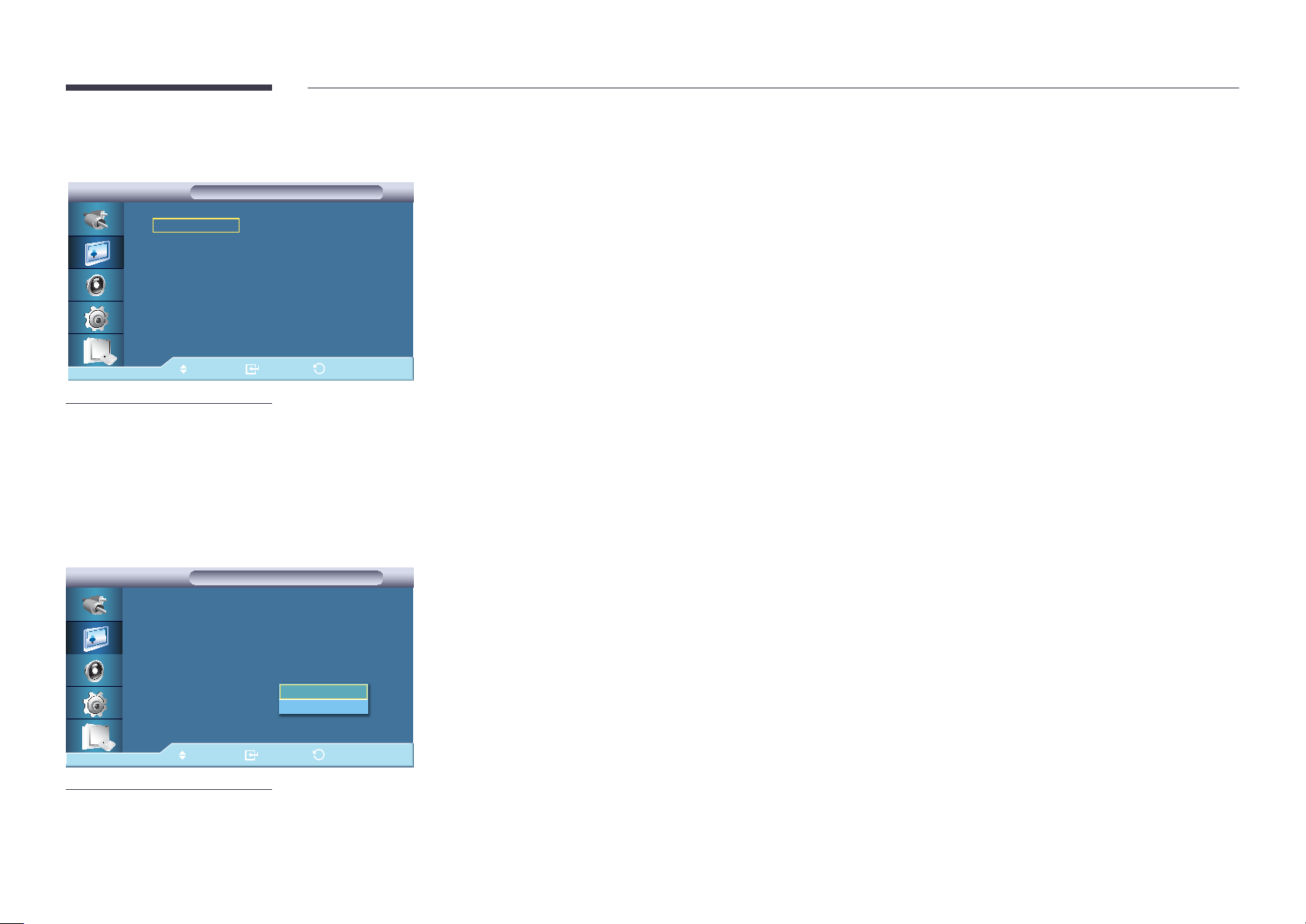
Size
Size
Size
16:9
Zoom1
Zoom2
4:3
Screen Fit
Custom
Move Enter Return
-
The displayed image may differ depending on the model.
▶
▶
▶
▶
The Size can be switched.
•
16:9
Sets the picture to 16:9 wide mode.
•
Zoom1
Magnifies the size of the picture on the screen.
•
Zoom2
Magnifies the size of the picture more than Zoom1.
•
4:3
Sets the picture to 4:3 normal mode.
•
Screen Fit
Displays the input scenes as they are without any cutoff when HDMI 720p, 1080i, 1080p signals are input.
•
Custom
Changes the resolution to suit the user's preferences.
Digital NR
Picture
Picture
Mode : Custom
Custom
Color Tone : Normal
Color Temp.
Size : 16:9
Digital NR :
HDMI Black Level :
▶
More
Move Enter Return
-
The displayed image may differ depending on the model.
Off
On
The Digital Noise Reduction feature allows you to enjoy clearer and crisper images.
•
Off / On
―
Digital NR function is not available for all resolutions.
72
Page 73
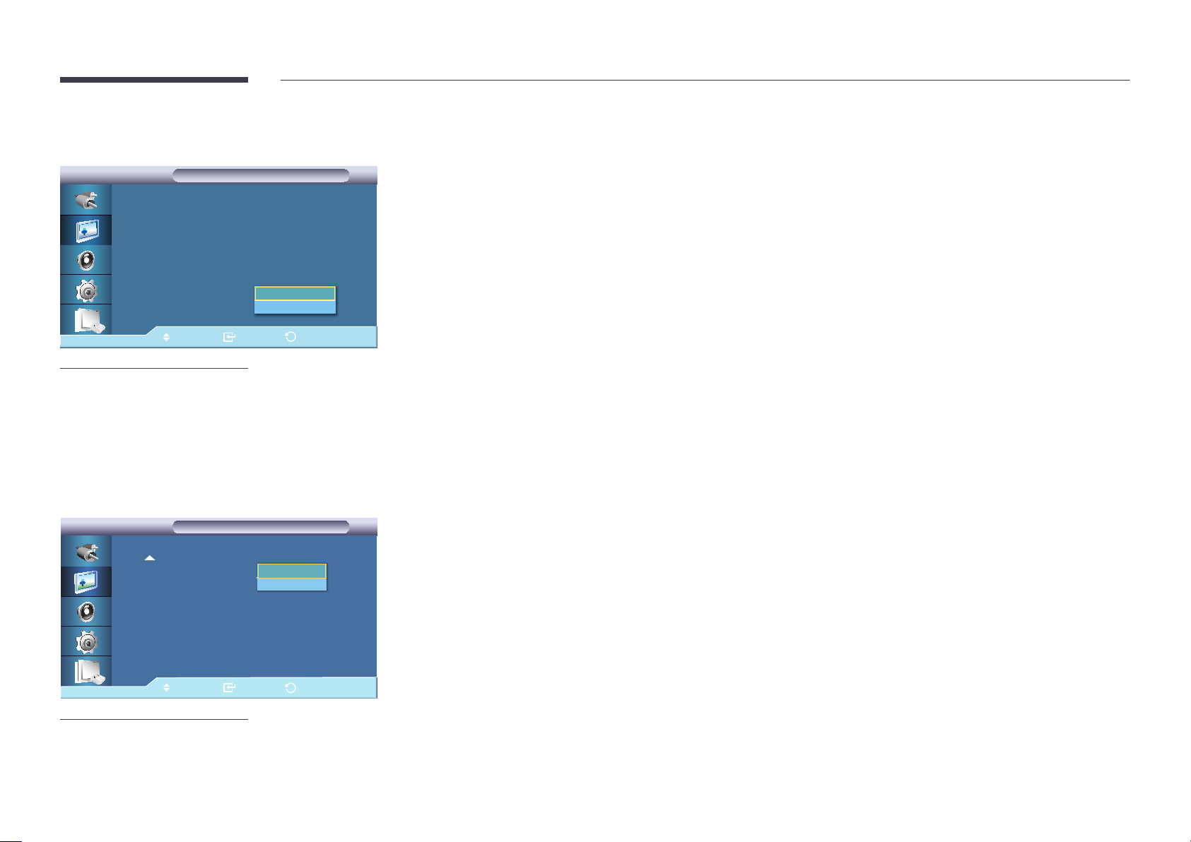
HDMI Black Level
Picture
Picture
Mode : Custom
Custom
Color Tone : Normal
Color Temp.
Size : 16:9
Digital NR : On
HDMI Black Level :
▶
More
Move Enter Return
-
The displayed image may differ depending on the model.
Normal
Low
When a DVD or set-top box is connected to your product via HDMI or DVI port, it may cause a degradation in the screen
quality, such as an increase in the black level, a low contrast, or discoloration, etc., depending on the external device connected.
In this case, adjust the screen quality of your product by configuring the HDMI Black Level.
•
Normal / Low
―
For Timing which can be used for both the PC and the DTV in HDMI and DTV mode, HDMI Black Level will be activated.
Film Mode
Picture
Picture
More
Film Mode :해제
PIP Picture
Dynamic Contrast :Off
Lamp Control :100
Brightness Sensor
Picture Reset
Move
-
The displayed image may differ depending on the model.
Off
On
Enter
Return
Film Mode calibrates unnatural picture when watching a movie (24 frames) played on a TV (30 frames).
Moving subtitles may appear corrupted when this mode is enabled.
―
In HDMI mode, this function is available when the input signal is interlaced scan; it is not available in progressive scan.
•
Off / On
73
Page 74
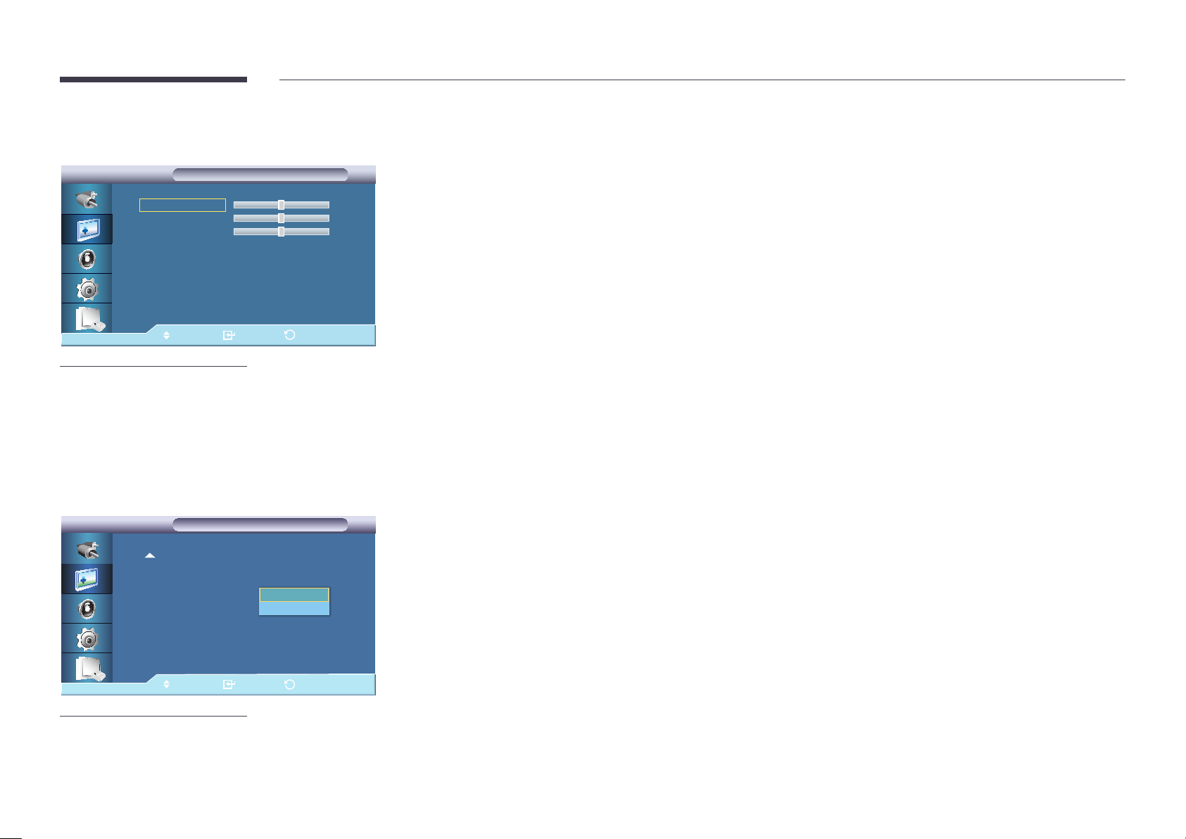
PIP Picture
PIP Picture
PIP Picture
Contrast
Brightness
Sharpness
Move Enter Return
-
The displayed image may differ depending on the model.
50
50
50
Adjusts the PIP Screen Settings.
•
Contrast
Adjusts the Contrast of the PIP window on the screen.
•
Brightness
Adjusts the Brightness of the PIP window on the screen.
•
Sharpness
Adjusts the Sharpness of the PIP window on the screen.
Dynamic Contrast
Picture
Picture
More
Film Mode :Off
PIP Picture
Dynamic Contrast :
Lamp Control :100
Brightness Sensor
Picture Reset
Move
-
The displayed image may differ depending on the model.
Off
On
Enter
Return
Dynamic Contrast automatically detects the distribution of the visual signal and adjusts to create an optimum contrast.
•
Off / On
―
This function is disabled when PIP or Energy Saving is On.
74
Page 75
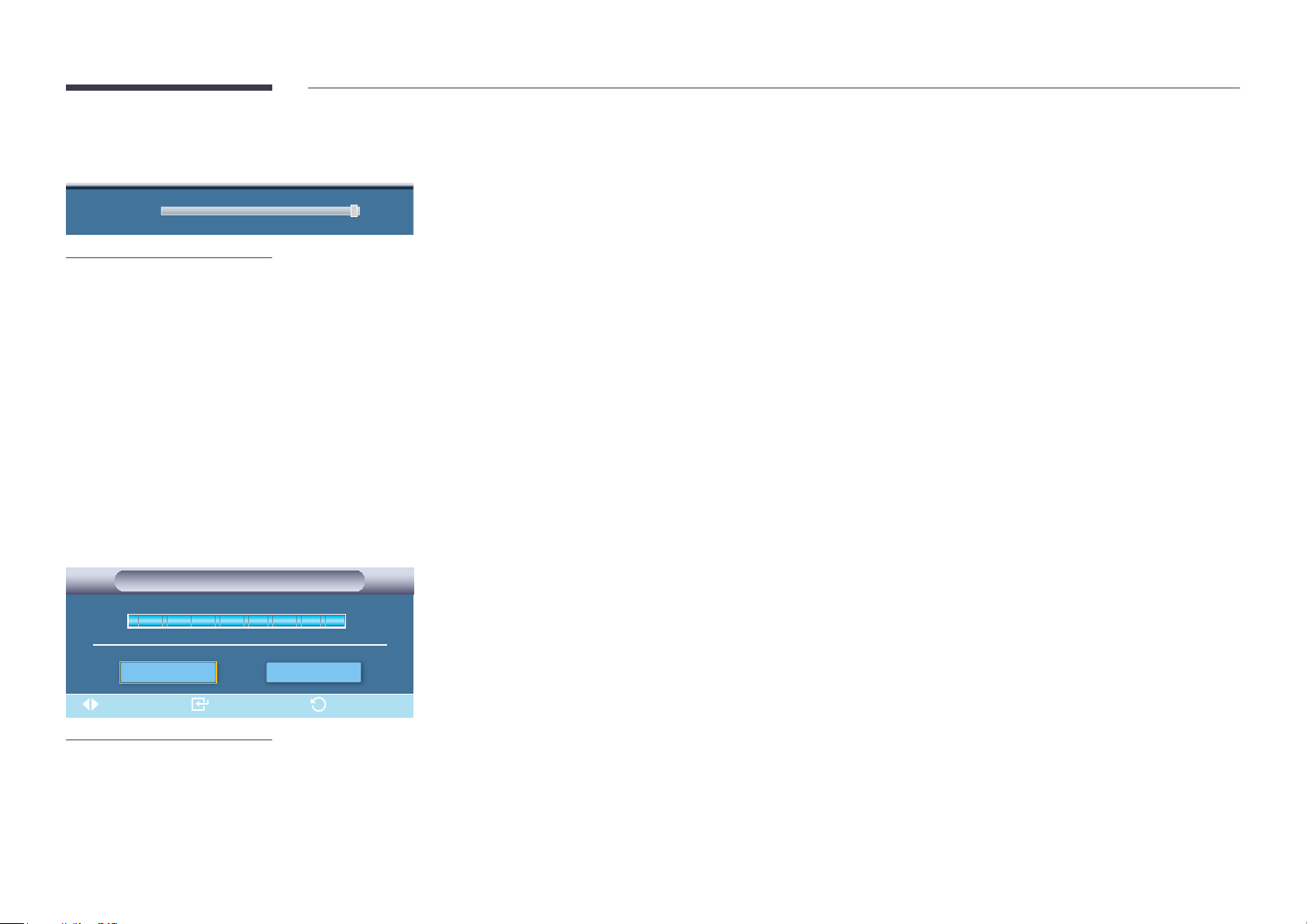
Lamp Control
Lamp Control 100
-
The displayed image may differ depending on the model.
Adjusts the inverter lamp in order to reduce energy consumption.
―
Not available when Dynamic Contrast is set to On.
Brightness Sensor
Brightness Sensor
Brightness Sensor
OnOff
Move Enter Return
-
The displayed image may differ depending on the model.
Brightness Sensor detects the ambient light intensity so that the picture brightness can automatically be adjusted.
•
Off / On
75
Page 76
Picture Reset
Reset the screen settings.
i
-
The displayed image may differ depending on the model.
Reset picture settings?
Yes No
76
Page 77
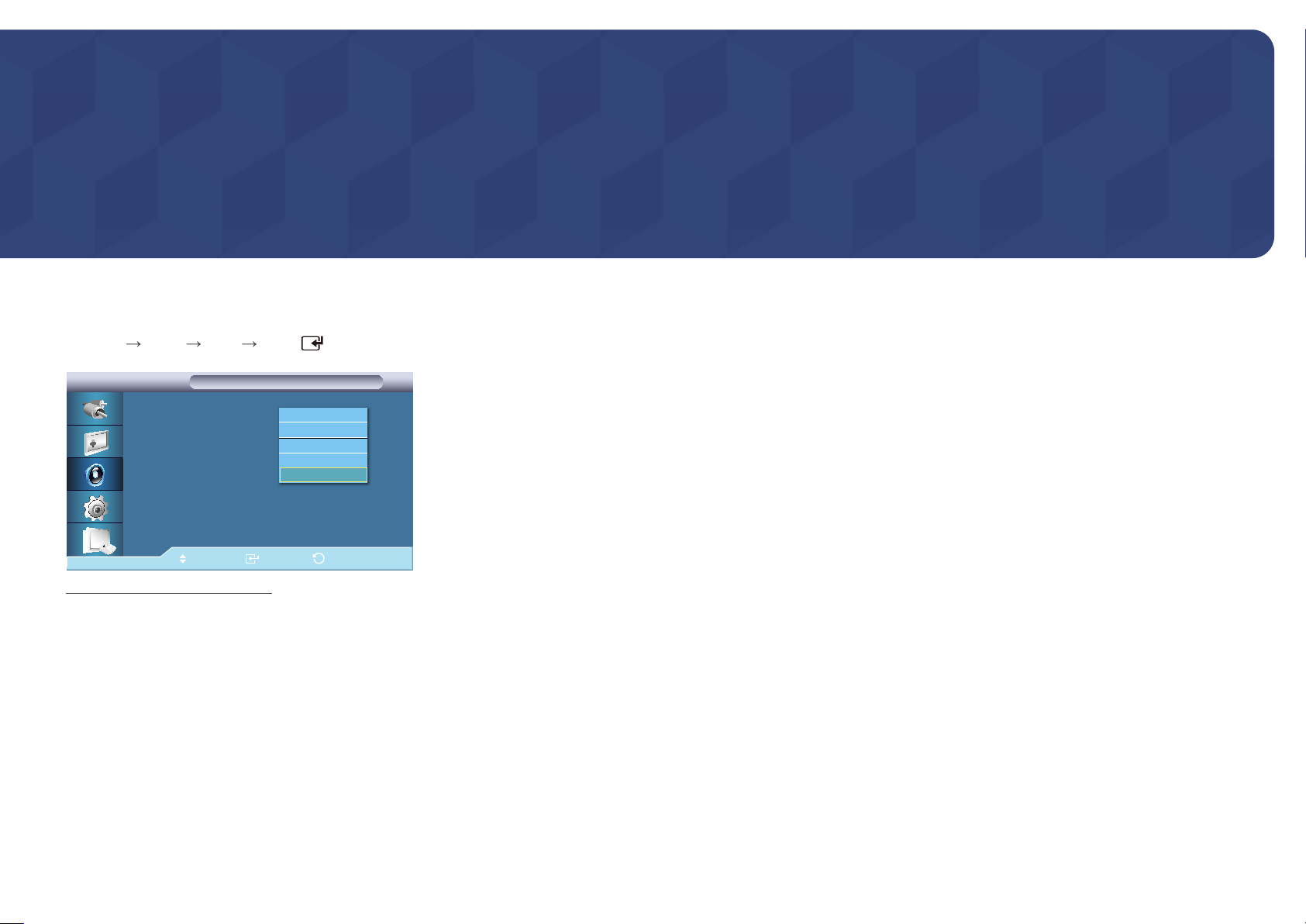
Chapter 07
Sound
Mode
MENU
-
Sound Mode ENTER
Sound
Sound
Mode : 사용자 조정
Custom
Auto Volume : 표준
SRS TS XT :
Sound Select : 주화면
Speaker Select : Internal
Sound Reset
Move Enter Return
The displayed image may differ depending on the model.
Standard
Music
Movie
Speech
Custom
The LCD Display has a built-in high fidelity stereo amplifier.
•
Standard
Selects Standard for the standard factory settings.
•
Music
Selects Music when watching music videos or concerts.
•
Movie
Selects Movie when viewing movies.
•
Speech
Selects Speech when watching a show that is mostly dialog (i.e., news).
•
Custom
Selects Custom if you want to adjust the settings according to your personal preferences.
77
Page 78
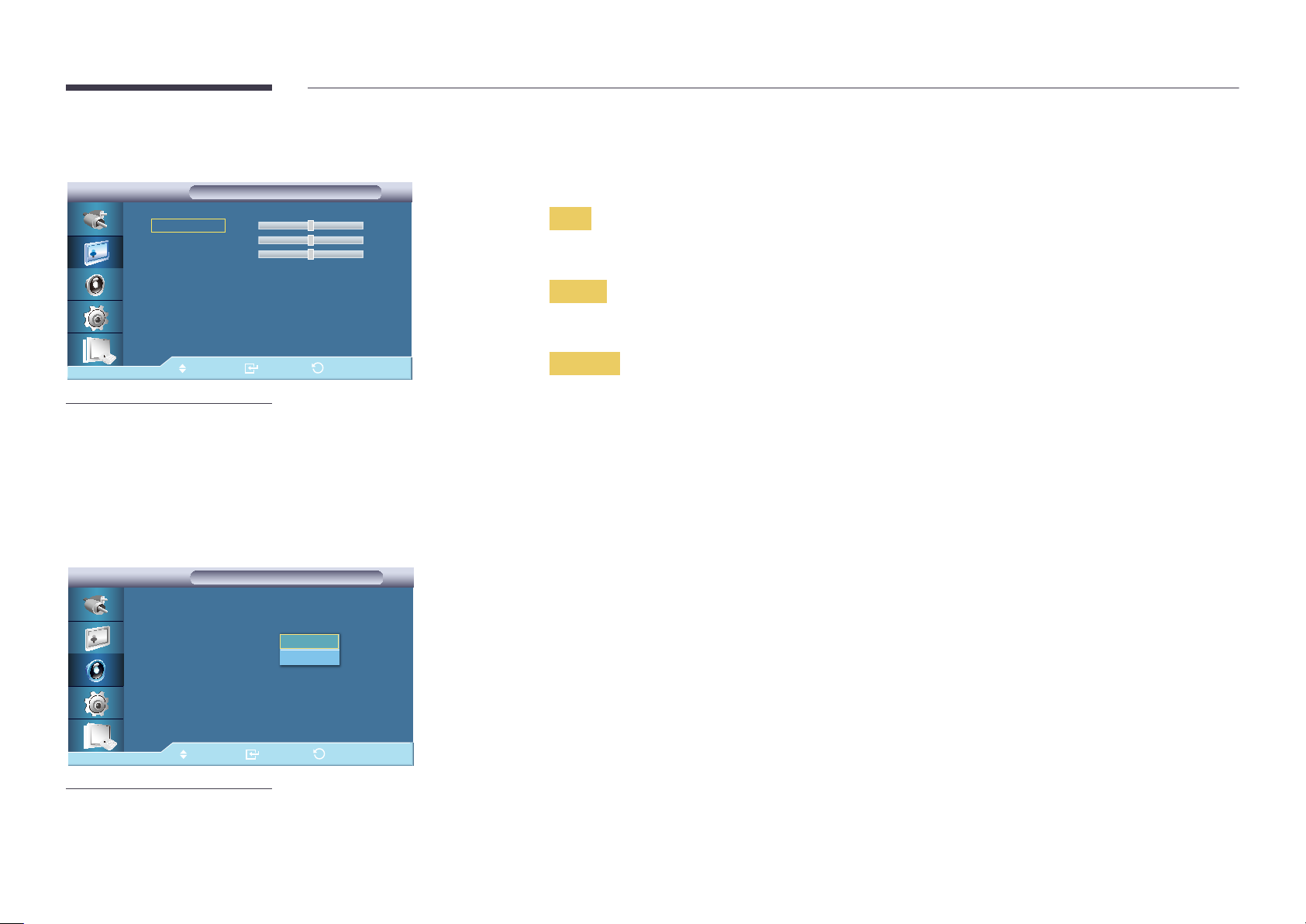
Custom
Custom
Custom
The sound settings can be adjusted to suit your personal preferences.
―
You can hear the sound even when sound value is set to 0.
―
If you adjust sound using Custom function, Mode will turn to Custom mode.
Bass
Treble
Balance L 50
Move Enter Return
-
The displayed image may differ depending on the model.
Auto Volume
Sound
Sound
Mode : Custom
Custom
Auto Volume : 표준
SRS TS XT :
Sound Select : Main
Speaker Select : Internal
Sound Reset
Off
On
50
50
R 50
Bass
Emphasizes low frequency audio.
Treble
Emphasizes high frequency audio.
Balance
Allows you to Adjusts the sound balance between the left and right speakers.
Reduces the difference in volume control between broadcasters.
•
Off / On
Move Enter Return
-
The displayed image may differ depending on the model.
78
Page 79
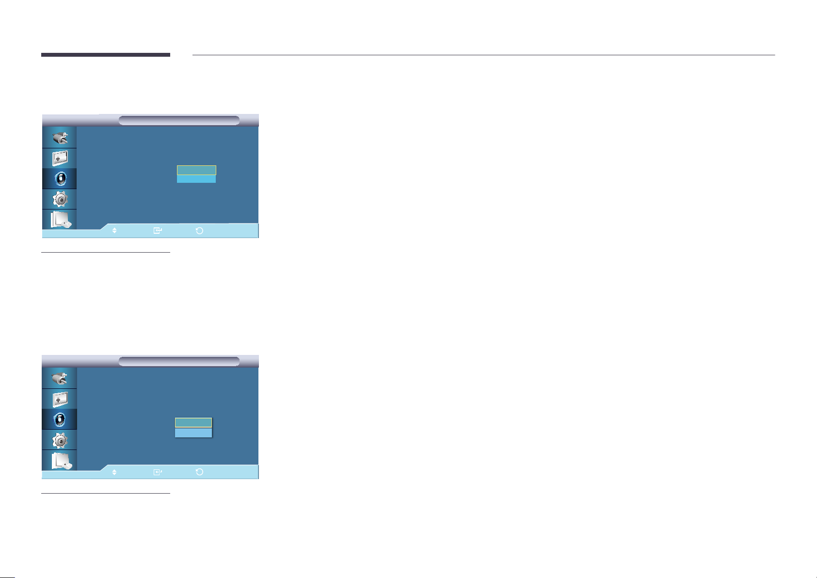
SRS TS XT
Sound
Sound
SRS TS XT is a patented SRS technology that solves the problem of playing 5.1 multichannel content over two speakers.
TruSurround XT delivers a compelling, virtual surround sound experience through any two-speaker playback system, including
internal television speakers. It is fully compatible with all multichannel formats.
•
Off / On
Mode :
Custom
Auto Volume :
SRS TS XT :
Sound Select
Speaker Select :
Sound Reset
Move
-
The displayed image may differ depending on the model.
Custom
Off
Off
On
Internal
Enter
Sound Select
Sound
Sound
Mode : Custom
Custom
Auto Volume : Off
SRS TS XT : Off
Sound Select : 면
Speaker Select
Sound Reset
Main
Sub
Return
Enable the sound of either the primary or secondary display in PIP mode.
―
Available when PIP is set to On.
•
Main / Sub
Move Enter Return
-
The displayed image may differ depending on the model.
79
Page 80
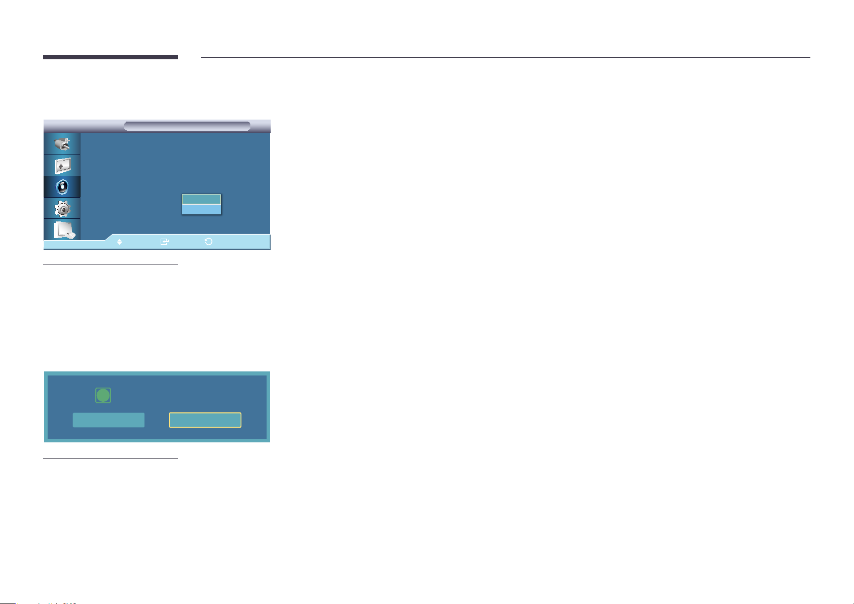
Speaker Select
Sound
Sound
Mode : Custom
Custom
Auto Volume : Off
SRS TS XT :
Sound Select : Main
Speaker Select : 내부
Sound Reset
Move Enter Return
-
The displayed image may differ depending on the model.
On
Internal
External
When you use the product with it connecting to a Home Theater, turn the internal speakers off so you can listen to sound from
the Home Theater's (external) speakers.
•
Internal
Sound is outputted both from the Internal speaker and the External speakers, but the volume control is only available
from the Internal speaker.
•
External
When sound is only outputted from the External speakers, the volume control is also only available from the External
speakers.
Sound Reset
Reset sound settings?
i
Yes No
-
The displayed image may differ depending on the model.
Reset the sound settings.
80
Page 81
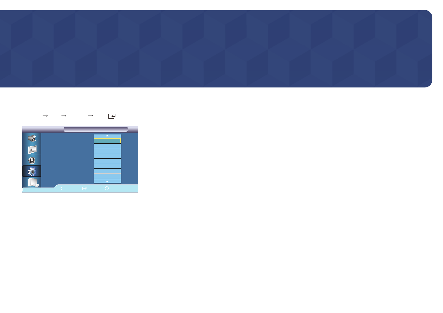
Chapter 08
Setup
Language
MENU
-
Setup Language ENTER
Setup
Setup
Language : 한국어
Time
Menu Transparency : 투명하게
Safety Lock
Energy Saving : 해제
Video Wall
Safety Screen
▶
More
Move Enter Return
The displayed image may differ depending on the model.
English
Deutsch
Español
Français
Italiano
Svenska
Русский
Português
You can choose one of 14 languages.
―
The language chosen affects only the language of the OSD. It has no effect on any software running on the computer.
English, Deutsch, Español, Français, Italiano, Svenska, Русский
Português ,Türkçe, Polish, 简体中文, 繁體中文 ,日本語, 한국어
81
Page 82
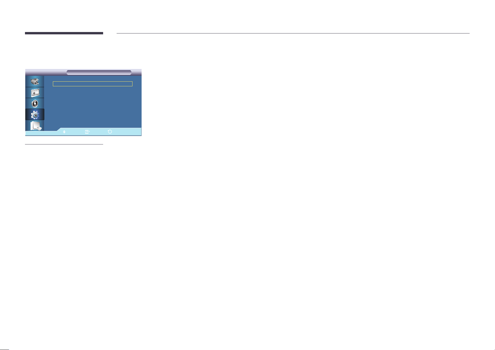
Time
Time
Time
Clock Set
Sleep Timer
Timer1
Timer2
Timer3
Holiday Management
Move Enter Return
-
The displayed image may differ depending on the model.
10:04 am ▶
: Off ▶
: Off ▶
: Off ▶
: Off ▶
▶
Selects from one of 4 time settings, Clock Set, Sleep Timer, Timer, and Holiday Management.
Clock Set
Current Time Setting.
Sleep Timer
Turns the LCD Display off automatically at certain times.
•
Off / 30 / 60 / 90 / 120 / 150 / 180
Timer1 / Timer2 / Timer3
You can set the LCD display to automatically turn on or off at a specified time.
―
Only enabled when the clock is set using the Clock Set menu.
―
The Manual option allows you to select a day of the week.
―
Holiday : When choose Apply, timer is not available on holiday; when choose Don't Apply, timer is available on holiday.
Holiday Management
•
Add
You can register holidays.
•
Delete Selected
You can delete selected holidays.
―
Only enabled when registered holidays are selected.
―
More than one holiday can be selected and deleted.
•
Delete All
You can delete all the registered holidays.
82
Page 83
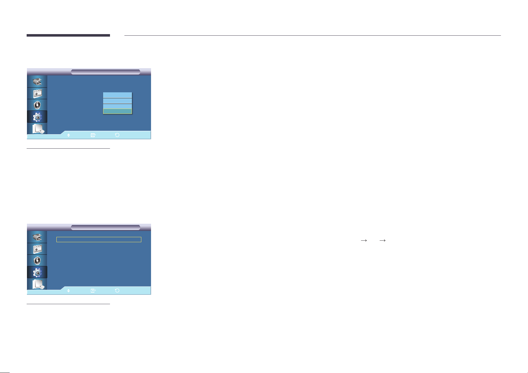
Menu Transparency
Setup
Setup
Language : English
Time
Menu Transparency : 투명하게
Safety Lock
Energy Saving : 해제
Video Wall
Safety Screen
▶
More
Move Enter Return
-
The displayed image may differ depending on the model.
High
Medium
Low
Opaque
Change the transparency of the background of the OSD.
•
High / Medium / Low / Opaque
Safety Lock
Safety Lock
Safety Lock
Change PIN
Lock
Move Enter Return
-
The displayed image may differ depending on the model.
▶
▶
Change PIN
The password can be changed.
The preset password for the LCD Display is "0000".
―
If you forgot your password, press the remote buttons INFO
EXIT MUTE to reset the password to "0000."
Lock
This is the function that locks the OSD in order to keep the current settings or to prevent others from adjusting the settings.
83
Page 84
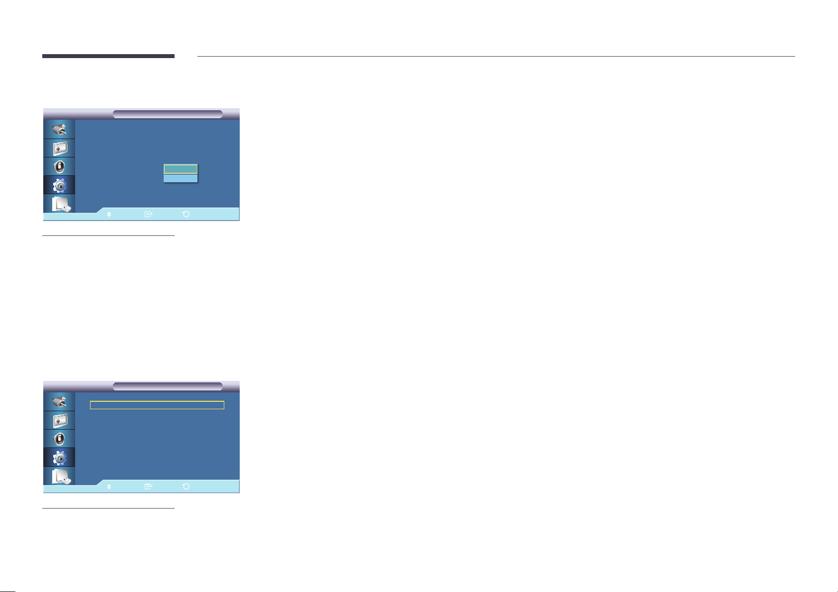
Energy Saving
Setup
Setup
Language : English
Time
Menu Transparency : High
Safety Lock
Energy Saving : 해제
Video Wall
Safety Screen
▶
More
Move Enter Return
-
The displayed image may differ depending on the model.
Off
On
This feature adjusts the power consumption of the unit in order to save energy.
•
Off / On
Video Wall
Video Wall
Video Wall
Video Wall
Video Wall
Format
Horizontal
Vertical
Screen Position
Move Enter Return
-
The displayed image may differ depending on the model.
: On ▶
: Full ▶
: 1
: 1
▶
▶
▶
A Video Wall is a set of video screens connected together, so that each screen shows a part of the whole picture or where the
same picture is repeated on each screen.
When the Video Wall is on, you can adjust the Video Wall screen setting.
―
When Video Wall is running, the Size functions are not available.
―
Disabled when PIP is set to On.
Turns Off/On the Video Wall function of the selected display Off/On.
•
Off / On
84
Page 85
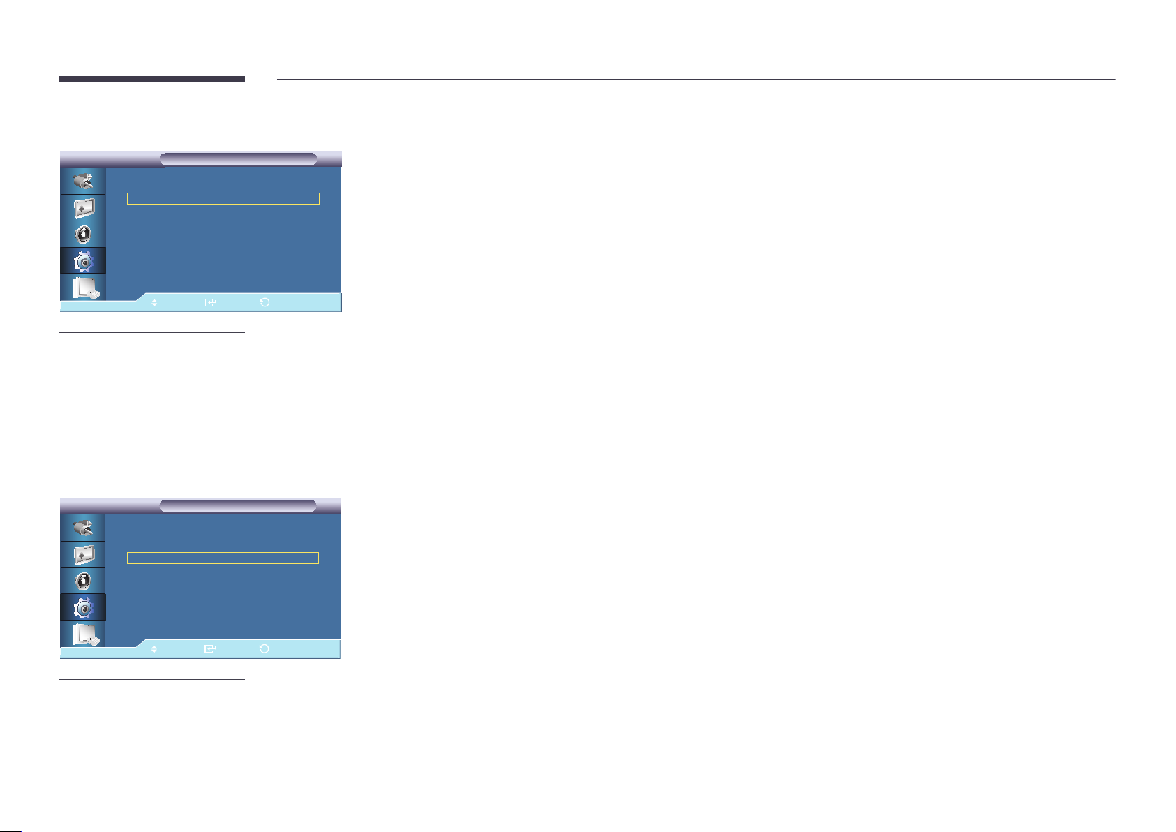
Format
Video Wall
Video Wall
Video Wall
Format
Horizontal
Vertical
Screen Position
Move Enter Return
-
The displayed image may differ depending on the model.
: On
: Full ▶
: 1
: 1
▶
▶
▶
▶
The Format can be selected to see a divided screen.
•
Full
Provides a full screen without any margins.
•
Natural
Displays a natural image with the original aspect ratio intact.
Horizontal
Video Wall
Video Wall
Video Wall
Format
Horizontal
Vertical
Screen Position
Move Enter Return
-
The displayed image may differ depending on the model.
: On
: Full
: 1
: 1
▶
▶
▶
▶
▶
Sets how many parts the screen should be divided horizontally.
Fifteen adjustment levels: 1~15.
―
If Vertical is set to 15, the maximum value for Horizontal is 6.
85
Page 86
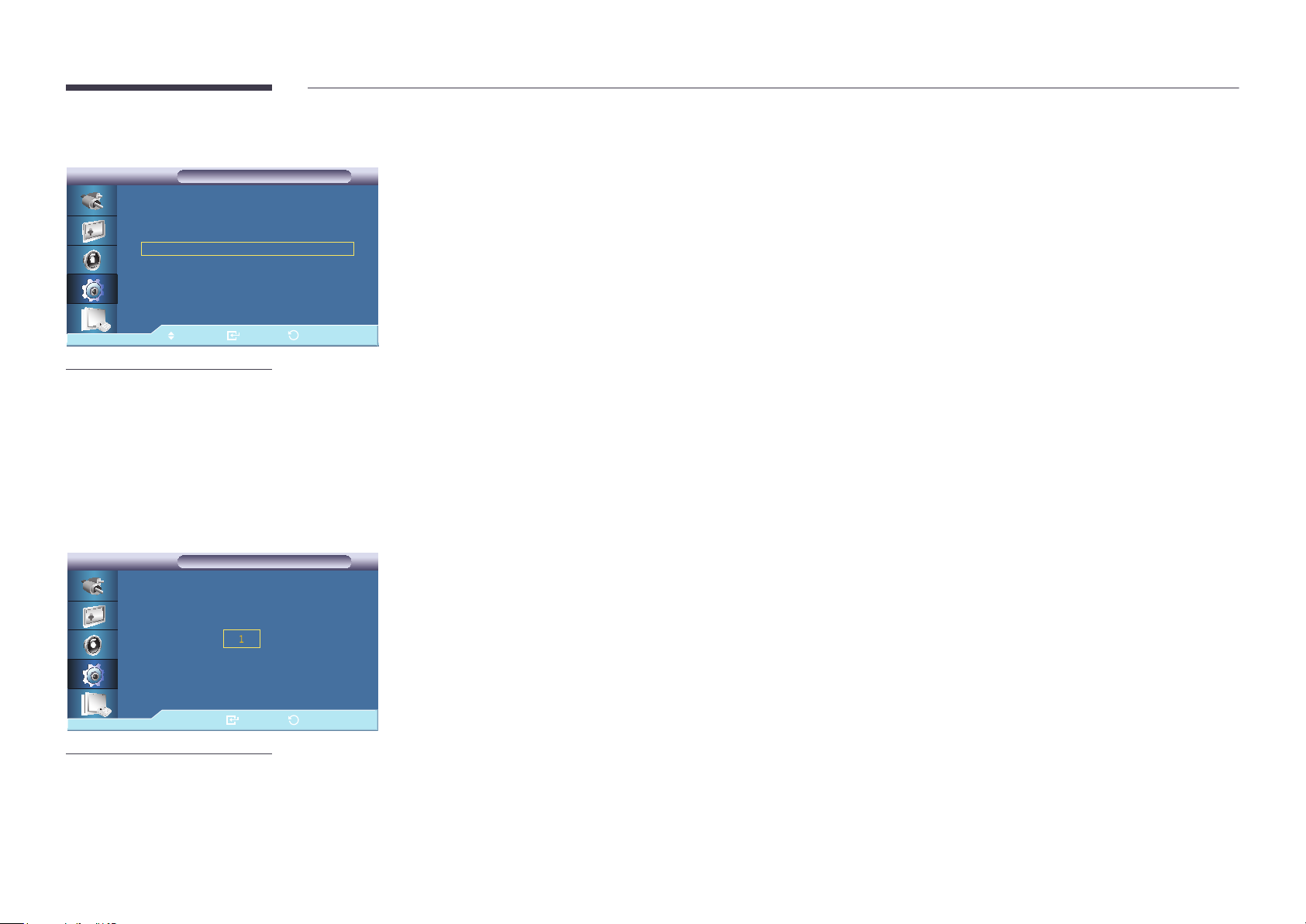
Vertical
Video Wall
Video Wall
Video Wall
Format
Horizontal
Vertical
Screen Position
Move Enter Return
-
The displayed image may differ depending on the model.
: On
: Full
: 1
: 1
▶
Sets how many parts the screen should be divided vertically.
Fifteen adjustment levels: 1~15.
―
If Horizontal is set to 15, the maximum value for Vertical is 6.
▶
▶
▶
▶
Screen Position
Screen Position
Screen Position
Enter Return
-
The displayed image may differ depending on the model.
The screen can be divided into several images. A number of screens can be selected with a different layout when dividing.
•
Select a mode in Screen Position.
•
Select a display in Display Selection.
•
The selection will be set up by pressing a number in the selected mode.
•
The screen can be split into a maximum of 100 sub-screens.
―
When more than four displays are connected, we recommend a resolution of XGA (1024*768) or greater to prevent any
picture degradation.
86
Page 87
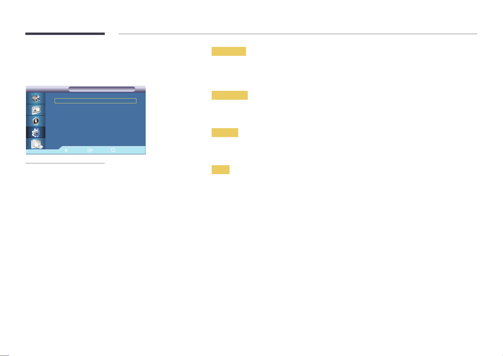
Safety Screen
Pixel Shift
Pixel Shift
Horizontal
Vertical
Time
Pixel Shift
Pixel Shift
: On
: 4
: 4
: 4 min
Pixel Shift
To prevent after-images on the screen, you can use this function to have pixels move on the LCD in the horizontal or vertical
direction.
•
Off / On
▶
▶
▶
▶
Horizontal
Sets how many pixels the screen moves horizontally.
Five adjustment levels: 0, 1, 2, 3, and 4.
Vertical
Move Enter Return
-
The displayed image may differ depending on the model.
Sets how many pixels the screen moves vertically.
Five adjustment levels: 0, 1, 2, 3, and 4.
Time
Set the time interval for performing the horizontal or vertical movement, respectively.
87
Page 88
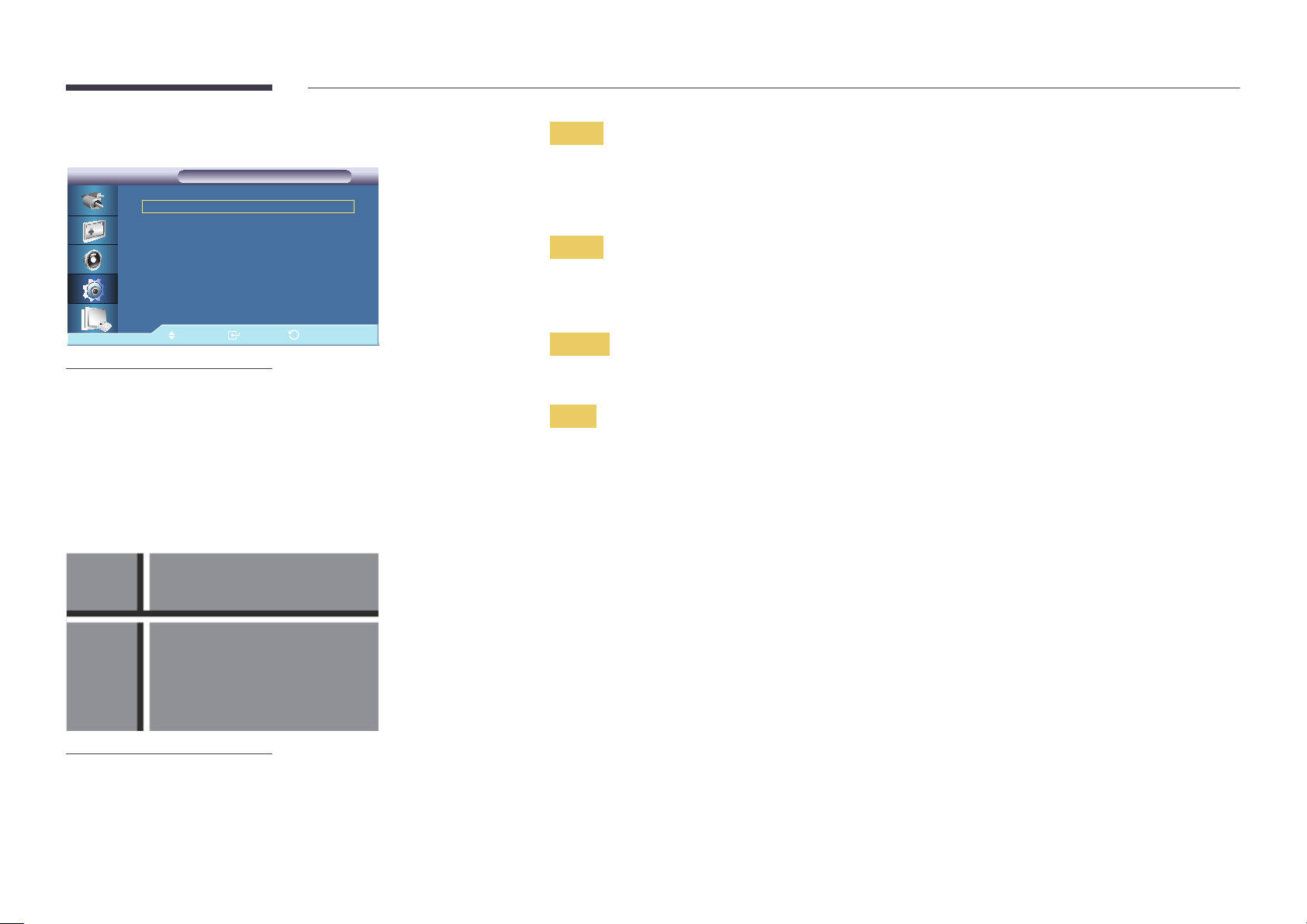
Timer
Timer
Mode
Period
Time
Timer
Timer
: On
: Bar
: 4 Hour
: 4 sec
Timer
You can set the timer for Screen Burn Protection. If you start the operation to erase any residual image, the operation will be
performed for the set period of time and then automatically finish.
▶
▶
▶
▶
•
Off / On
Mode
You can change the Safety Screen Type.
•
Bar / Eraser / Pixel
Move Enter Return
-
The displayed image may differ depending on the model.
Bar
-
The displayed image may differ depending on the model.
Period
Use this function to set the execution period for each mode set in the Timer.
Time
Within the set Period of time specify a time for execution.
This function prevents after-images on the screen by moving long black and white vertical lines.
88
Page 89
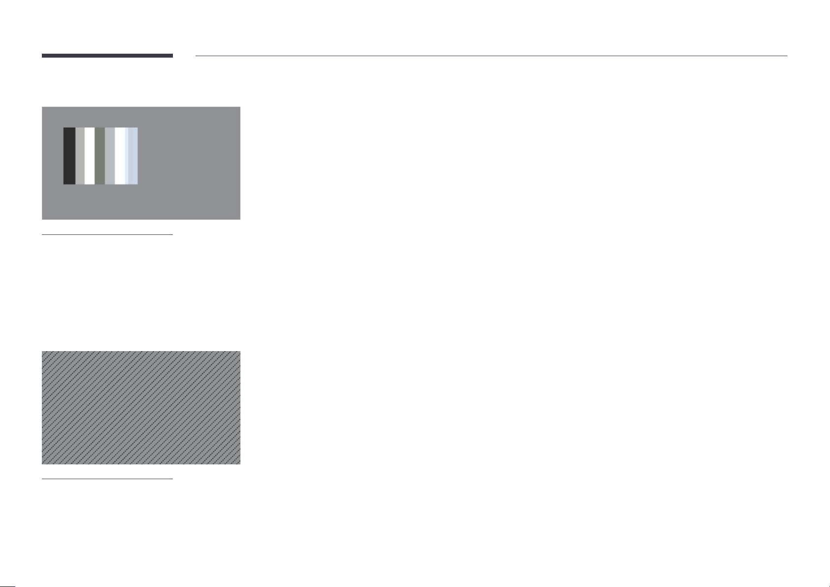
Eraser
-
The displayed image may differ depending on the model.
This function prevents after-images on the screen by moving a rectangular pattern.
Pixel
-
The displayed image may differ depending on the model.
This function prevents after-images by moving many pixels on the screen.
89
Page 90
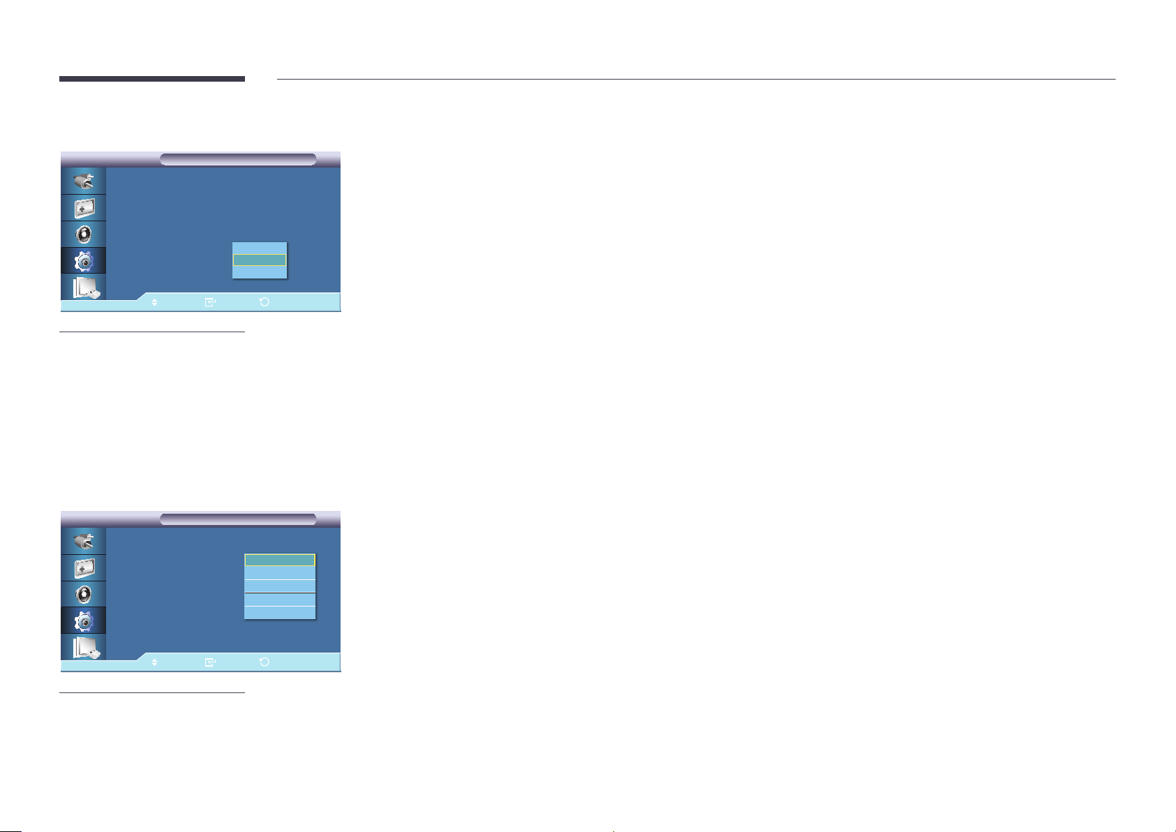
Side Gray
Safety Screen
Safety Screen
Pixel Shift
Timer
Bar
Eraser
Pixel
Side Gray :
Move Enter Return
-
The displayed image may differ depending on the model.
Off
Light
Dark
Select the brightness of the grey for the screen background.
•
Off / Light / Dark
Resolution Select
Setup
Setup
▶
More
Resolution Select : 가로
Power On Adjustment
OSD Rotation : 가로
Advanced Settings
Setup Reset
Reset All
S/N : - - - - - - - - - - - - - - - - - -
Move Enter Return
-
The displayed image may differ depending on the model.
-
Available in PC mode only.
Off
1024 X 768
1280 X 768
1360 X 768
1366 X 768
When the picture is not displayed properly on the screen when setting the graphics card resolution of the computer to 1024
x 768 @ 60Hz, 1280 x 768 @ 60Hz, 1360 x 768 @ 60Hz or 1366 x 768 @ 60Hz, by using this function(Resolution Select), you
can have the picture displayed on the screen in the specified resolution.
―
Selecting the menu is only allowed when the graphics resolution is set to 1024 x 768 @ 60Hz, 1280 x 768 @ 60Hz, 1360 x
768 @ 60Hz or 1366 x 768 @ 60Hz.
•
Off / 1024 X 768 / 1280 X 768 / 1360 X 768 / 1366 X 768
90
Page 91
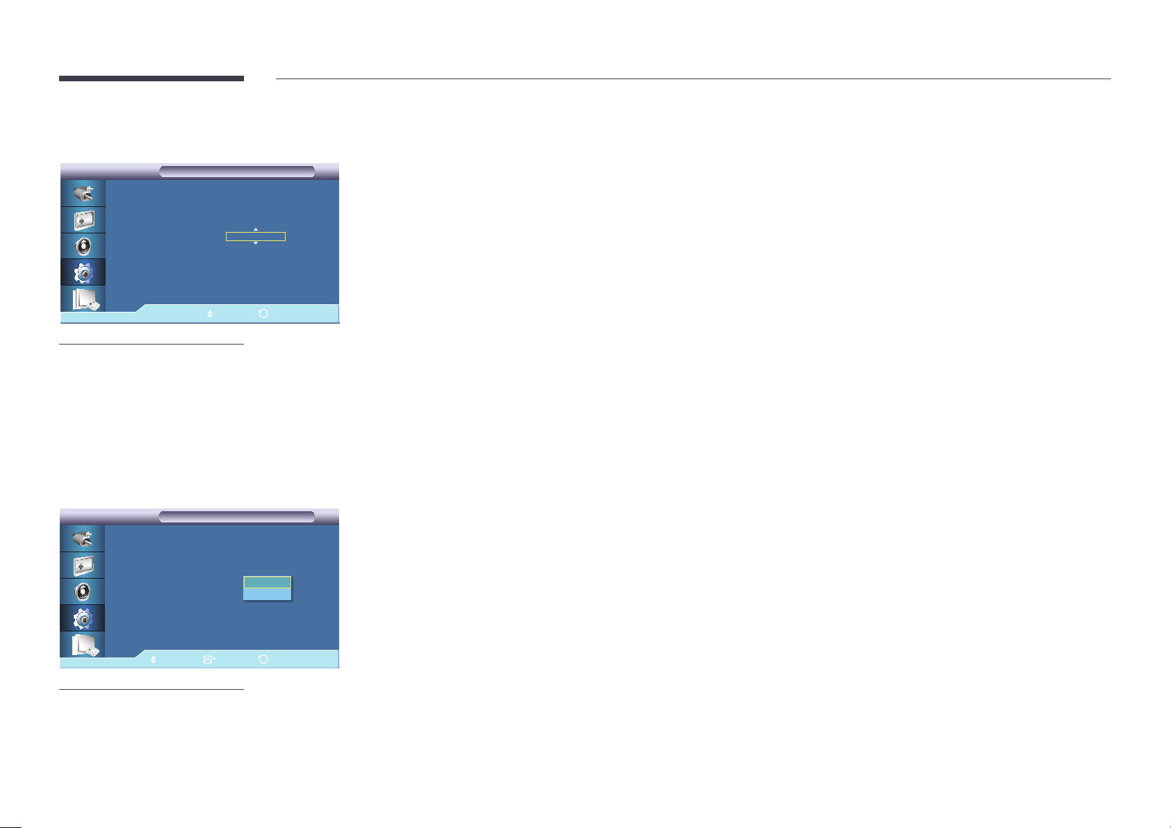
Power On Adjustment
Power On Adjustment
Power On Adjustment
Power On Adjustment : 0
Adjust Return
-
The displayed image may differ depending on the model.
Adjusts the Power On time for the screen.
―
Set the Power On time to be longer to avoid overvoltage.
OSD Rotation
Setup
Setup
▶
More
Resolution Select : Off
Power On Adjustment
OSD Rotation :
Advanced Settings
Setup Reset
Reset All
S/N : - - - - - - - - - - - - - - - - - -
Move Enter Return
-
The displayed image may differ depending on the model.
Landscape
Portrait
OSD Rotate
•
Landscape / Portrait
91
Page 92
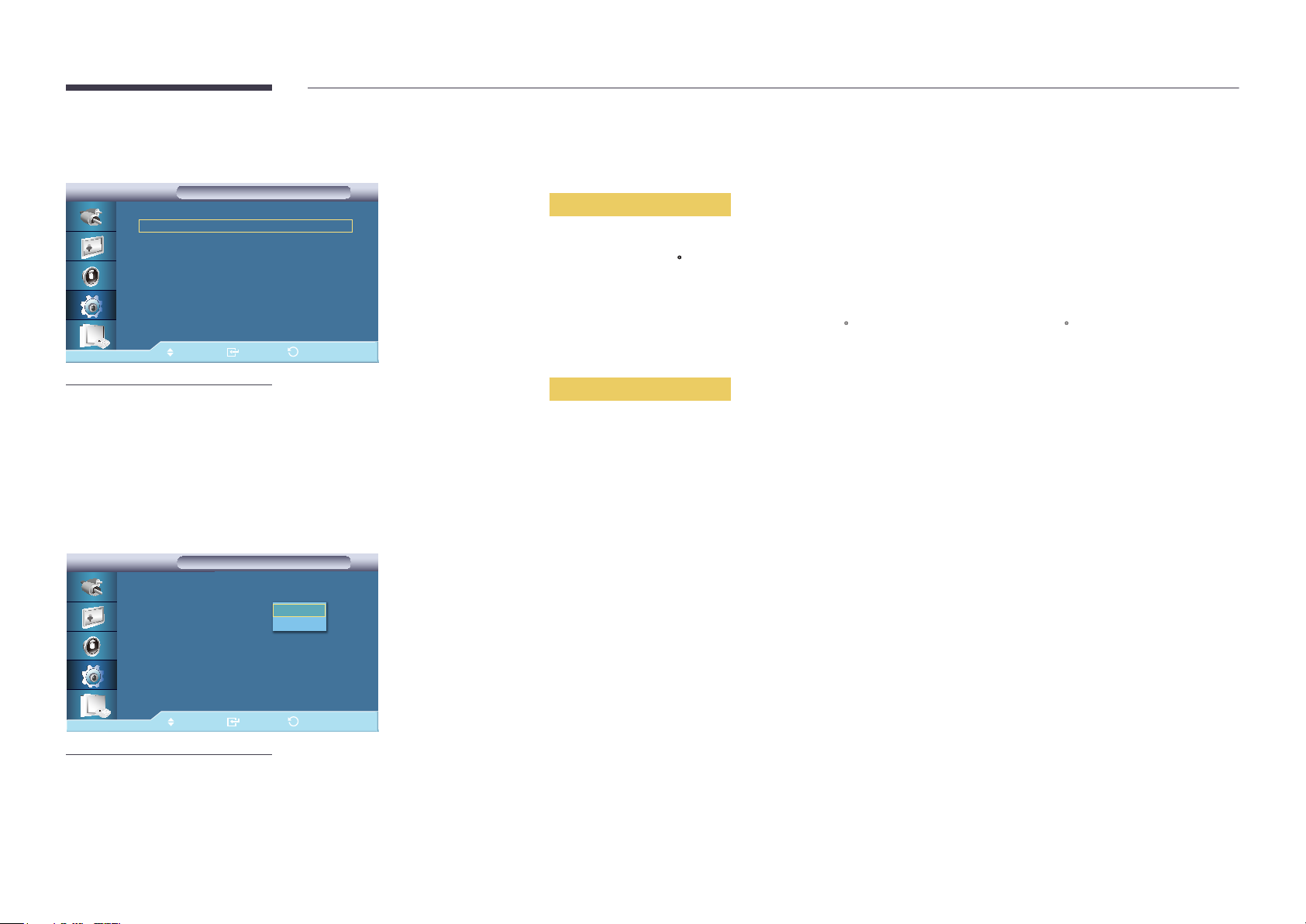
Advanced Settings
Advanced Settings
Advanced Settings
Temperature
Auto Power : Off
Button Lock : Off
User Auto Color
Standby Control : Auto
Lamp Schedule
OSD Display
Software Upgrade
Move Enter Return
Temperature
Configures the setting for the Temperature function, which detects the internal temperature for the product's protection.
Temperature Control
▶
▶
▶
▶
▶
▶
▶
▶
Detects the product's internal temperature and specifies the desired temperature.
The product is set to 77
―
The picture will be dimmed if the temperature exceeds the specified temperature, and the product will automatically power
C by default.
off to prevent overheating if the temperature keeps rising.
―
It is best to use the product at temperatures 75 - 80
C (based on ambient temperature of 40 C).
Refer to "Specifications" herein for details about operating conditions.
-
The displayed image may differ depending on the model.
Auto Power
Advanced Settings
Advanced Settings
Temperature
Auto Power :
Button Lock :
User Auto Color
Standby Control : Auto
Lamp Schedule
OSD Display
Software Upgrade
Move Enter Return
-
The displayed image may differ depending on the model.
Off
On
Current Temperature
Shows the current temperature of the product.
Enables or disables Auto Power for the product.
•
Off / On
―
When Auto Power is On, the product will power on automatically as soon as it is connected to power.
92
Page 93
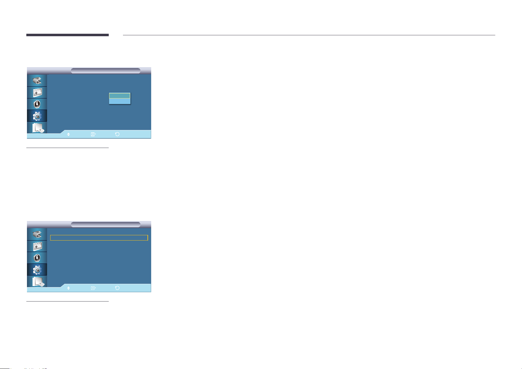
Button Lock
Advanced Settings
Advanced Settings
Temperature
Auto Power : Off
Button Lock :
User Auto Color
Standby Control : Auto
Lamp Schedule
OSD Display
Software Upgrade
Move Enter Return
-
The displayed image may differ depending on the model.
Off
On
User Auto Color
User Auto Color
User Auto Color
Auto Color
Reset
Locks or unlocks the monitor control buttons on the product.
•
Off / On
•
Auto Color
Automatically adjusts the colors.
•
Reset
Resets the color settings.
Move Enter Return
-
The displayed image may differ depending on the model.
―
Enabled only in PC mode.
93
Page 94
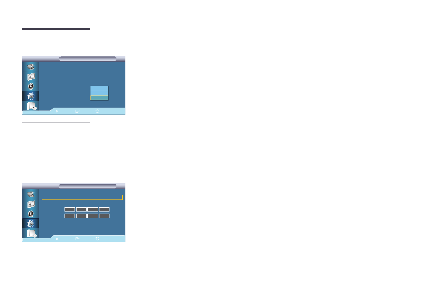
Standby Control
Advanced Settings
Advanced Settings
Temperature
Auto Power : Off
Button Lock : Off
User Auto Color
Standby Control : 자동설정
Lamp Schedule
OSD Display
Software Upgrade
Move Enter Return
-
The displayed image may differ depending on the model.
Off
On
Auto
Sets the standby mode, which will be activated when no input signal is detected.
•
Off
A message will read No Signal if no input signal is detected.
•
On
Power-saving mode will be activated if no input signal is detected.
•
Auto
When no input signal is detected,
―
Power-saving mode will be activated if an external device is connected.
―
A message will read No Signal if no external device is connected.
―
Enabled only in PC, DVI mode.
―
Auto will be disabled in HDMI mode.
Lamp Schedule
Lamp Schedule
Lamp Schedule
Lamp Schedule : On
Hour
Minute
Schedule 1
Schedule 2
-
The displayed image may differ depending on the model.
12 00 am
12 00 am
Move Enter Return
Lampam/pm
100
100
Adjusts the luminance to a user-specified value at a specified time.
▶
94
Page 95
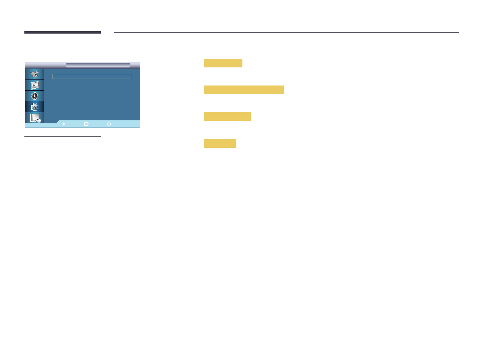
OSD Display
Displays or hides a menu item on the screen.
OSD Display
OSD Display
Source OSD
Not Optimum Mode OSD
No Signal OSD
MDC OSD
Move Enter Return
-
The displayed image may differ depending on the model.
: On ▶
: On ▶
: On ▶
: On ▶
Source OSD
•
Off / On
Not Optimum Mode OSD
•
Off / On
No Signal OSD
•
Off / On
MDC OSD
•
Off / On
95
Page 96
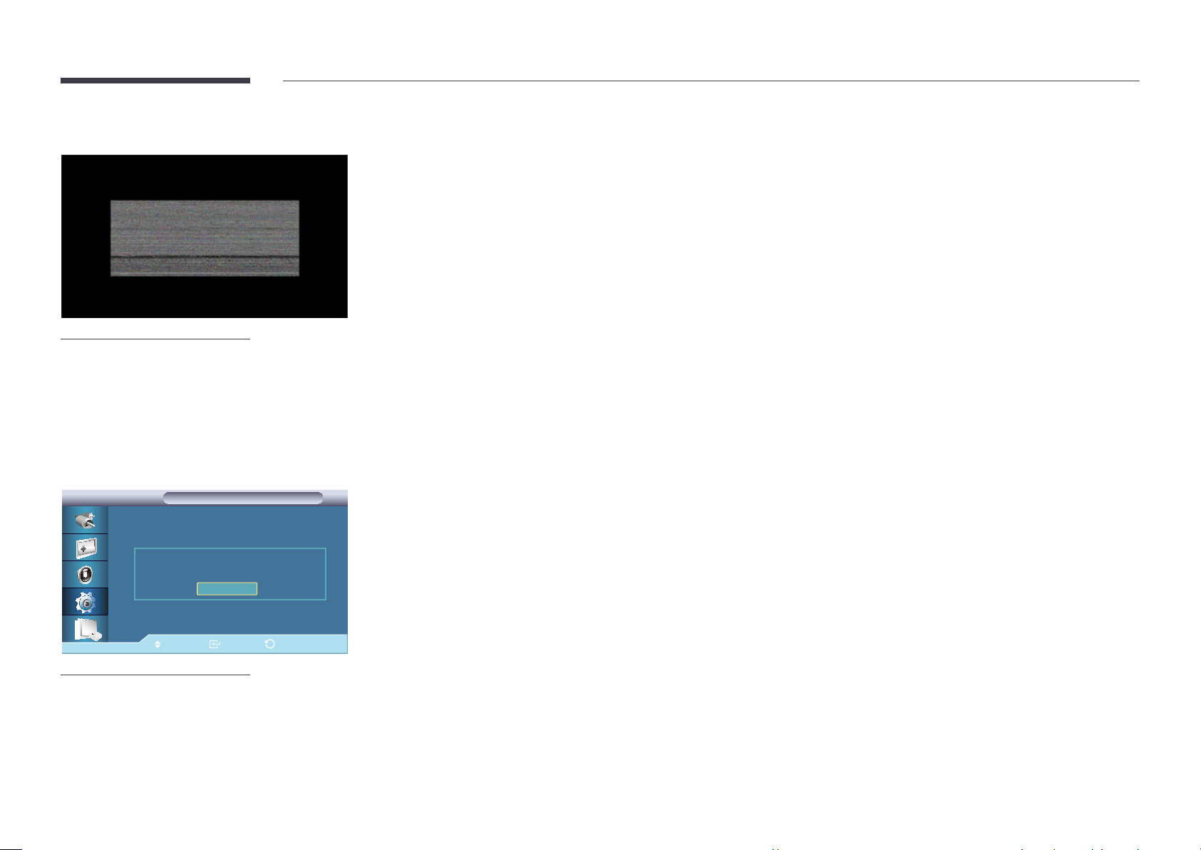
Software Upgrade
-
When there are two or more BMP images, they are displayed on the screen using a
slideshow.
-
It is recommended that the playback interval between two BMP images in the slideshow
should be one second. The image extraction probability will decrease with other playback
intervals.
-
A BMP image might not be extracted if it is covered by another image (for example, the mouse
pointer).
Advanced Settings
Advanced Settings
Temperature
Auto Power : Off
버튼 잠금 : 해제
Upgrade is completed.
사용자 자동 색상 조정
Power will be off and turned on automatically.
대기 모드 설정 : 자동설정
휘도 조정 기능
OSD Display
Software Upgrade
OK
Performs a software upgrade.
Connect the product to a computer via a digital signal such as DVI or HDMI. Click the BMP image file converted from an
1
SW code. The image below will appear on the screen of the product.
While a BMP image onto which the software code has been converted is displayed on the screen, select Software
2
Upgrade.
If a more recent version than the current software version is detected, you will be asked whether to upgrade the current
3
software. If you select Yes , the upgrade is performed.
When the software upgrade is completed, the product is turned off and on automatically.
4
―
This only operates with a digital signal, such as in DVI, HDMI1, or HDMI2 mode. (The input resolution must be identical to
the panel resolution.)
―
In HDMI1 and HDMI2 modes, the timing values used for both the PC and TV are only supported if the Edit Name is set to
PC or DVI PC.
―
This is only supported if the Size is set to 16:9.
Move Enter Return
-
The displayed image may differ depending on the model.
96
Page 97
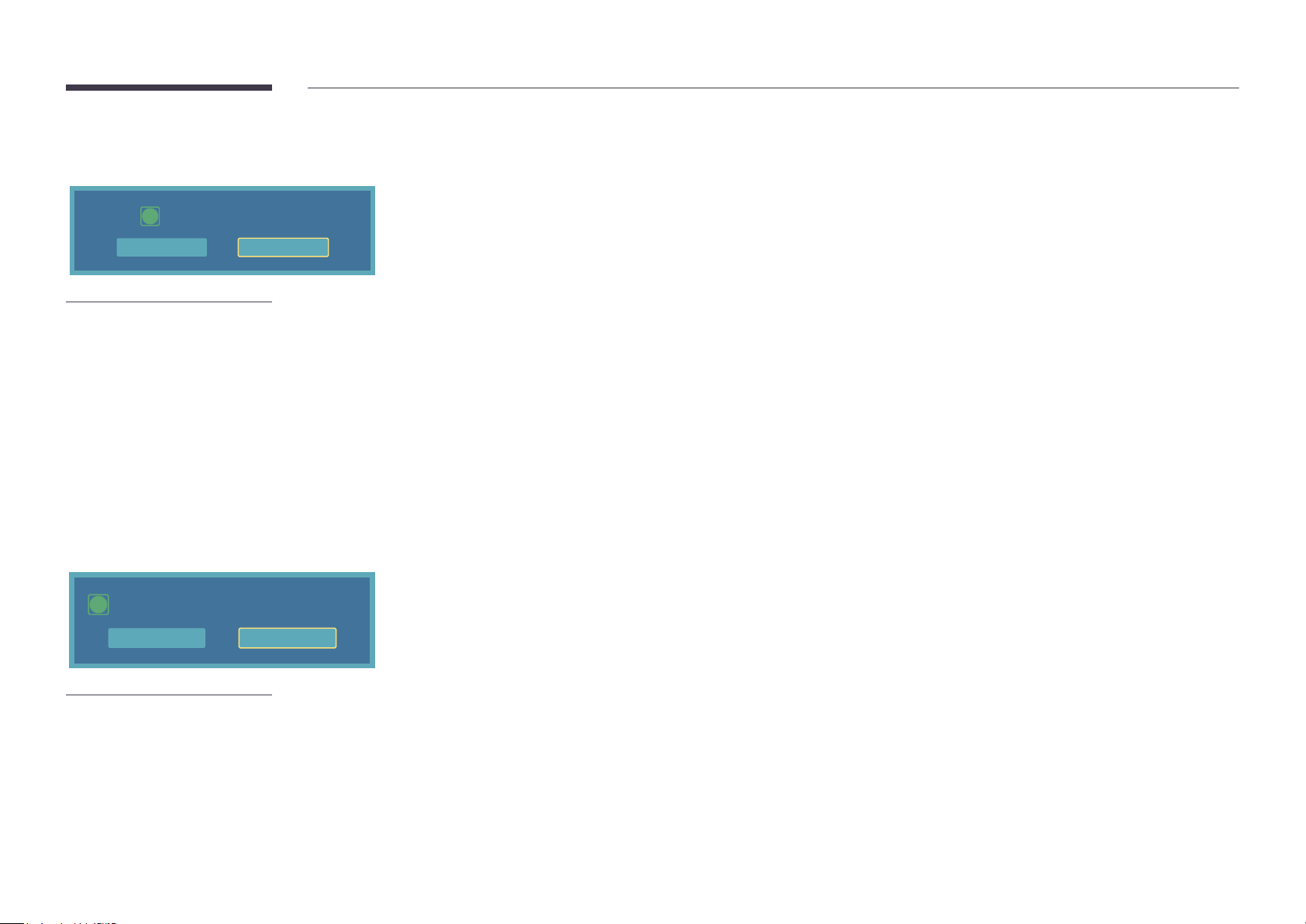
Setup Reset
Reset settings in setup?
i
Yes No
-
The displayed image may differ depending on the model.
Reset all the values for a setting.
Reset All
All Settings return to default settings.
i
Yes No
-
The displayed image may differ depending on the model.
Reset all the settings for the display.
97
Page 98
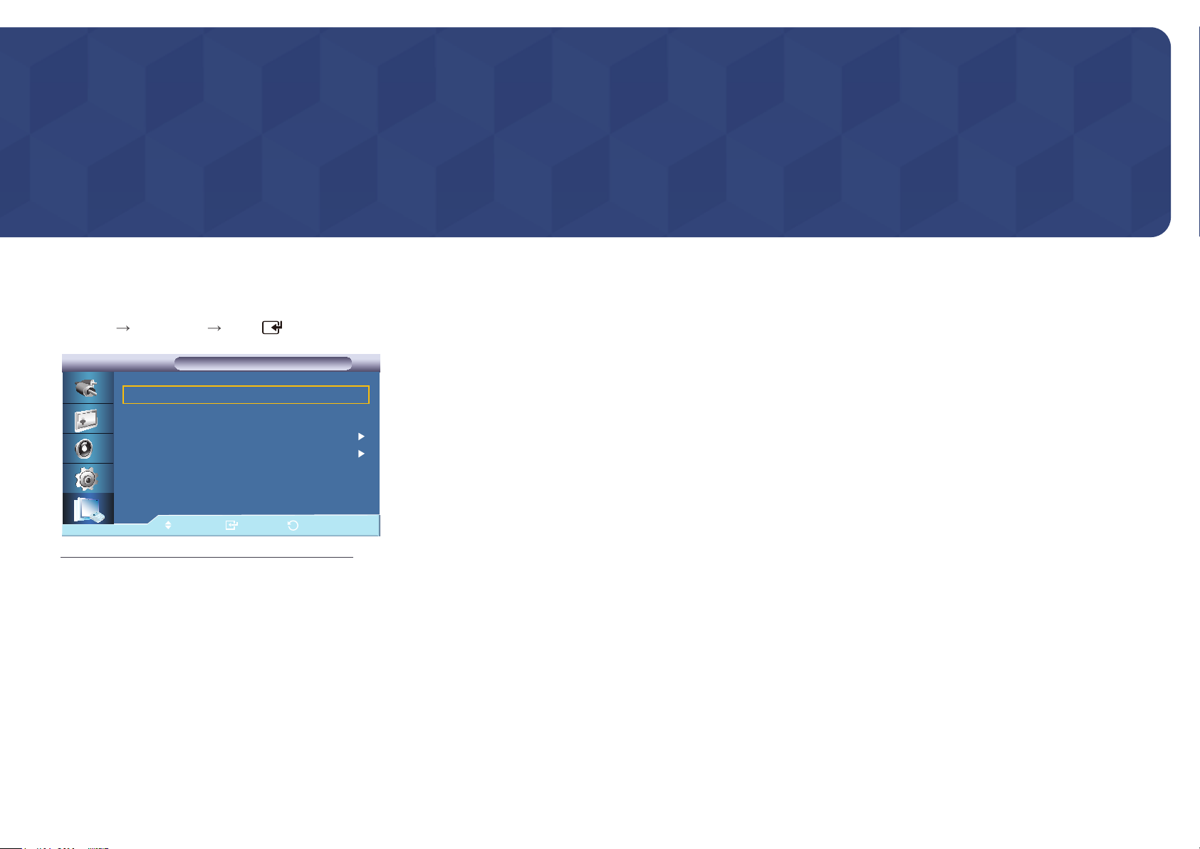
Chapter 09
Using MDC
MDC (Multiple Display Control) is an application that allows you to easily control multiple display devices simultaneously using a PC.
Multi Control
MENU
Multi Control ENTER
ID Setup : 00
ID Input : --
MDC Connection : RJ45 MDC
Network Setting
Move
Multi Control
Multi Control
Enter
Return
•
•
•
•
ID Setup
Assigns distinctive IDs to the SET.
ID Input
Use to select the transmitter functions of the individual SET. Only a SET where the ID corresponds
to the transmitter setting becomes activated.
MDC Connection
Selects a port to receive the MDC inputs from.
―
RS232C MDC: Communicates with the MDC via a RS232C MDC cable.
―
RJ45 MDC: Communicates with the MDC via an RJ45 MDC cable.
Network Setting
IP Setting : Manual, Auto
IP Address : Manually enter the IP Address if IP Setting is set to Manual.
Subnet Mask : Manually enter the Subnet Mask if IP Setting is set to Manual.
Gateway : Manually enter the Gateway if IP Setting is set to Manual.
-
The displayed image may differ depending on the model.
98
Page 99

MDC Program Installation/Uninstallation
Installation
MDC installation can be affected by the
graphics card, mother board and network
conditions.
If a software installation window is not
displayed on the main screen, install with
the MDC Unified execution file in the
MDC folder on the CD.
If the directory path is not specified, the
program will be installed in the default
directory path.
Select "Launch MDC Unified" and
click "Finish" to run the MDC program
immediately.
Insert the installation CD into the CD-ROM drive.
1
Click the MDC Unified installation program.
2
Select a language for installation. Next, click "OK".
3
When the "Welcome to the InstallShield Wizard for MDC_Unified" screen appears, click "Next".
4
In the "License Agreement" window displayed, select "I accept the terms in the license agreement" and click "Next".
5
In the displayed "Customer Information" window, fill out all the information fields and click "Next".
6
In the displayed "Destination Folder" window, select the directory path you want to install the program in and click "Next".
7
In the displayed "Ready to Install the Program" window, check the directory path to install the program in and click "Install".
8
Installation progress will be displayed.
9
Click "Finish" in the displayed "InstallShield Wizard Complete" window.
10
The MDC Unified shortcut icon will be created on the desktop after installation.
11
-
The MDC execution icon may not be
displayed depending on the PC system
or product specifications.
-
Press F5 if the execution icon is not
displayed.
Uninstallation
Select Settings > Control Panel on the Start menu and double-click Add/Delete Program.
1
Select MDC Unified from the list and click Change/Remove.
2
99
Page 100
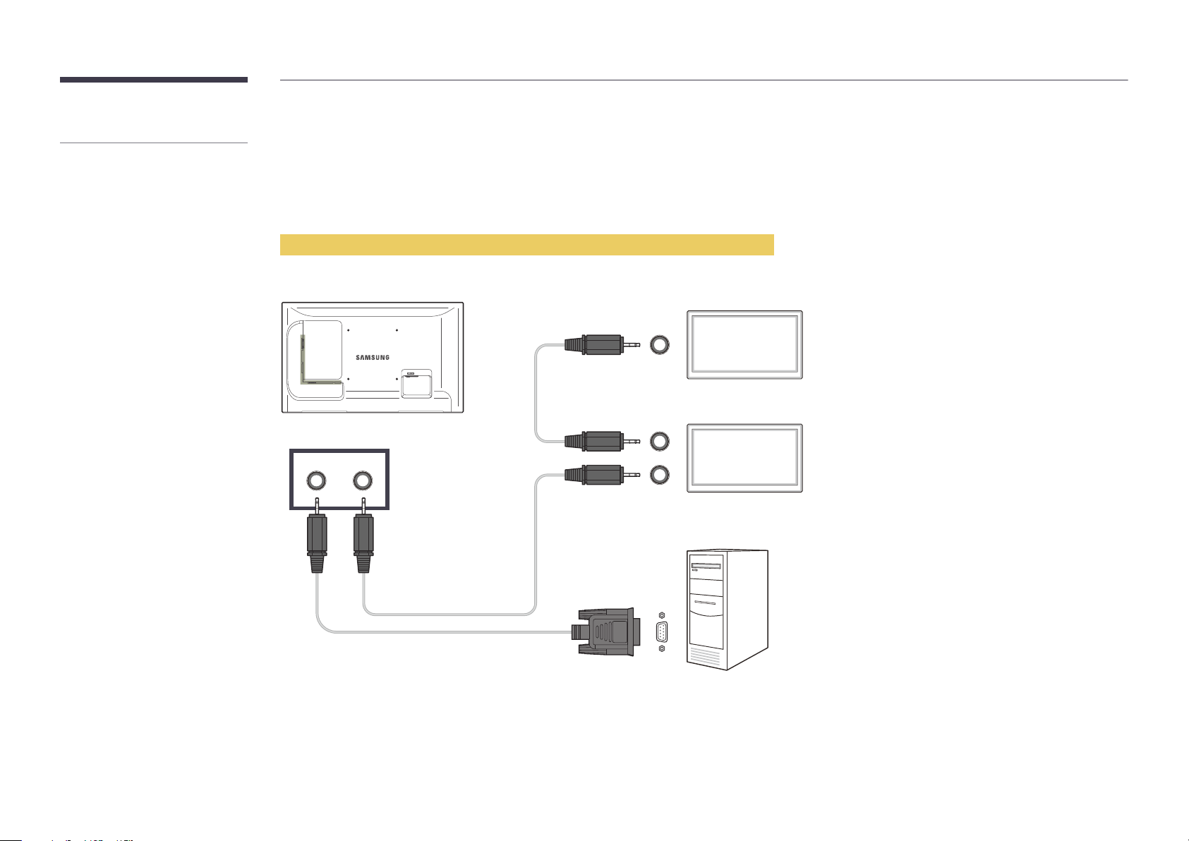
Multiple display control "MDC" is an
application that allows you to easily
control multiple display devices
simultaneously using a PC.
What is MDC?
Connecting to MDC
Using MDC via RS-232C (serial data communications standards)
An RS-232C serial cable must be connected to the serial ports on the PC and monitor.
Monitor 1
RS232C IN/OUT
Monitor 2
Computer
100
 Loading...