

Samsung LE23R86BD, LE26R86BD, LE37R81BX, LE40R86BD, LE40R81BX Service Manual
...
TFT-LCD TV
Chassis GBP23SEN
GBP26SEN
GBP32SEN
GBP37SEN
GBP40SEN
Model LE23R86BD
LE26R86BD
LE32R86BD
LE32R81BX
LE37R86BD
LE37R81BX
LE40R86BD
LE40R81BX
Manual
SERVICE
TFT-LCD TV Fashion Feature
- Luxurious Slim Design
- Supreme Picture Quality
- Supreme Sound Quality
- Supreme Convenience Quality
- Convenience for Users
- iDTV

ii
Copyright
ⓒ 2007 by Samsung Electronics Co., Ltd.
All rights reserved.
This manual may not, in whole or in part, be copied,
photocopied, reproduced, translated, or converted to any
electronic or machine readable form without prior
written permission of Samsung Electronics Co., Ltd.
LE23R86BD/LE26R86BD/LE32R86BD/
LE32R81BX/LE37R86BD/LE37R81BX/LE40R86BD/
LE40R81BX Service Manual
First edition March 2007.
Printed in Korea.
Trademarks
Samsung is the registered trademark of Samsung
Electronics Co., Ltd.
LE23R86BD/LE26R86BD/LE32R86BD/
LE32R81BX/LE37R86BD/LE37R81BX/LE40R86BD/
LE40R81BX Service Manual and Macmaster Cable
Adapter are trademarks of Samsung Electronics Co.,
Ltd.
Macintosh and Power Macintosh are trademarks of
Apple Computer, Inc.
All other trademarks are the property of their respective
owners.

Contents
11. Precautions
………………………………………………………………………………………………………………………………………
11-1
1-1 Safety Precautions ……………………………………………………………………………………………………………………… 1-1
1-2 Servicing Precautions …………………………………………………………………………………………………………………… 1-2
1-3 Static Electricity Precautions …………………………………………………………………………………………………………… 1-2
1-4 Installation Precautions…………………………………………………………………………………………………………………… 1-3
2
2. Product specifications
…………………………………………………………………………………………………………………………
22-1
2-1 Fashion Feature…………………………………………………………………………………………………………………………… 2-1
2-2 LE23R86BD Specifications ……………………………………………………………………………………………………………… 2-2
2-3 LE26R86BD Specifications ……………………………………………………………………………………………………………… 2-3
2-4 LE32R86BD Specifications ……………………………………………………………………………………………………………… 2-4
2-5 LE37R86BD Specifications ……………………………………………………………………………………………………………… 2-5
2-6 LE40R86BD Specifications ……………………………………………………………………………………………………………… 2-6
2-7 Spec Comparison ………………………………………………………………………………………………………………………… 2-7
2-8 Option Specification ……………………………………………………………………………………………………………………… 2-8
3
3. Alignments and Adjustments
…………………………………………………………………………………………………………………
33-1
3-1 Service Instruction ……………………………………………………………………………………………………………………… 3-1
3-2 How to Access Service Mode …………………………………………………………………………………………………………… 3-2
3-3 Factory Data ……………………………………………………………………………………………………………………………… 3-3
3-4 Service Adjustment ……………………………………………………………………………………………………………………… 3-11
3-5 Software Upgrade ……………………………………………………………………………………………………………………… 3-14
4
4. Troubleshooting
………………………………………………………………………………………………………………………………
44-1
4-1 First Checklist for Troubleshooting ………………………………………………………………………………………………………4-1
4-2 Checkpoints by Error Mode ……………………………………………………………………………………………………………… 4-2
5
5. Exploded View and Parts List
…………………………………………………………………………………………………………………
55-1
5-1 LE23R86BD Exploded View ………………………………………………………………………………………………………………5-1
5-2 LE23R86BD Parts list …………………………………………………………………………………………………………………… 5-2
5-3 LE26R88BD Exploded View …………………………………………………………………………………………………………… 5-3
5-4 LE26R88BD Parts list …………………………………………………………………………………………………………………… 5-4
5-5 LE32R86BD Exploded View …………………………………………………………………………………………………………… 5-5
5-6 LE32R86BD Parts list …………………………………………………………………………………………………………………… 5-6
5-7 LE37R86BD Exploded View …………………………………………………………………………………………………………… 5-7
5-8 LE37R86BD Parts list …………………………………………………………………………………………………………………… 5-8
5-9 LE40R88BD Exploded View …………………………………………………………………………………………………………… 5-7
5-10 LE40R88BD Parts list …………………………………………………………………………………………………………………… 5-8

Contents
66. Electrical Parts List
……………………………………………………………………………………………………………………………
66-1
6-1 LE23R86BDX Parts List ………………………………………………………………………………………………………………… 6-1
6-2 LE26R88BDX Parts List ………………………………………………………………………………………………………………… 6-26
6-3 LE40R88BDX Parts List ………………………………………………………………………………………………………………… 6-50
7
7. Block Diagram
…………………………………………………………………………………………………………………………………
77-1
8. WWiring Diagram
…………………………………………………………………………………………………………………………………
88-1
8-1Wiring Diagram………………………………………………………………………………………………………………………………8-1
8-2 Main Board Layout ……………………………………………………………………………………………………………………… 8-2
8-3 PIN characteristic ………………………………………………………………………………………………………………………… 8-3
8-4 Connector Location and PCB outline figure …………………………………………………………………………………………… 8-6
8-5 Output Connector ………………………………………………………………………………………………………………………… 8-7
99. Schematic Diagrams
……………………………………………………………………………………………………………………………
99-1
10. OOperating Instructions and Installation
………………………………………………………………………………………………………
1
10-1
10-1 Front …………………………………………………………………………………………………………………………………… 10-1
10-2 Viewing the Connection Panel ……………………………………………………………………………………………………… 10-2
10-3 Remote control ………………………………………………………………………………………………………………………… 10-5
10-4 Installation the Stand ………………………………………………………………………………………………………………… 10-6
10-5 Installing the Wall Mount Kit ………………………………………………………………………………………………………… 10-6
1
11. Disassembly and Reassembly
………………………………………………………………………………………………………………
111-1
11-1 Disassembly …………………………………………………………………………………………………………………………… 11-1
11-2 Reassembly …………………………………………………………………………………………………………………………… 11-5
1
12. PCB Diagram
…………………………………………………………………………………………………………………………………
112-1
12-1 Main PCB Diagram (Without Card Slot) …………………………………………………………………………………………… 12-1
12-2 Main PCB Diagram (With Card Slot) …………………………………………………………………………………………………12-2
113. Circuit Descriptions
……………………………………………………………………………………………………………………………
113-1
13-1 Main Signal Description ……………………………………………………………………………………………………………… 13-1
13-2 DTV Signal Description ……………………………………………………………………………………………………………… 13-2
13-3 RF/DTV Tuner (DNOS403MH261B(S)) SPEC. …………………………………………………………………………………… 13-3
13-4 DTV MAIN ChipSet …………………………………………………………………………………………………………………… 13-9
1
14. Reference Infomation
………………………………………………………………………………………………………………………
114-1
14-1 Technical Terms ……………………………………………………………………………………………………………………… 14-1
14-2 Pin Assignments ……………………………………………………………………………………………………………………… 14-4
14-3 Timing Chart …………………………………………………………………………………………………………………………… 14-7
14-4 Panel Description …………………………………………………………………………………………………………………… 14-11

Samsung Electronics Co.,Ltd.
416, Maetan-3Dong, Yeongtong-Gu, Suwon City,
Gyeonggi-Do, Korea, 443-742
Printed in Korea
P/N : BN82-00183B-00
URL : http://itself.sec.samsung.co.kr/
- This Service Manual is a property of
Samsung Electronics Co., Ltd.
Any unauthorized use of Manual can be
punished under applicable International
and/or domestic law.
1 Precautions
1-1
1-1-1 Warnings
1. For continued safety, do not attempt to modify the
circuit board.
2. Disconnect the AC power and DC Power Jack before
servicing.
1-1-2 Servicing the LCD Monitor
1. When servicing the LCD Monitor Disconnect the AC
line cord from the AC outlet.
2. It is essential that service technicians have an accurate
voltage meter available at all times. Check the
calibration of this meter periodically.
1-1-3 Fire and Shock Hazard
Before returning the monitor to the user, perform the
following safety checks:
1. Inspect each lead dress to make certain that the leads
are not pinched or that hardware is not lodged between
the chassis and other metal parts in the monitor.
2. Inspect all protective devices such as nonmetallic
control knobs, insulating materials, cabinet backs,
adjustment and compartment covers or shields,
isolation resistor-capacitor networks, mechanical
insulators, etc.
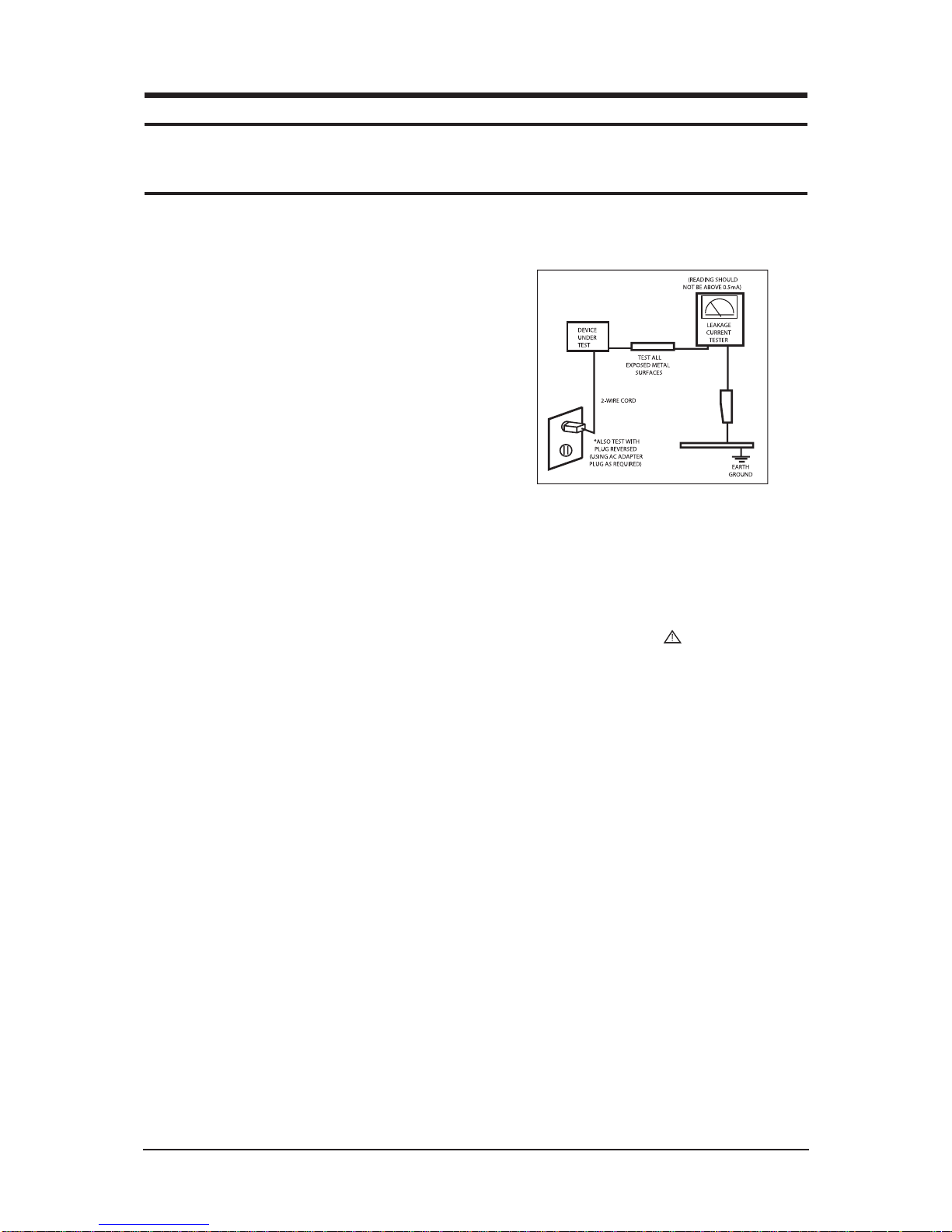
3. Leakage Current Hot Check (Figure 1-1):
WARNING: Do not use an isolation
transformer during
th
Use a leakage current tester or a metering system that
complies with American National Standards Institute
(ANSI C101.1, Leakage Current for Appliances), and
Underwriters Laboratories (UL Publication UL1410,
59.7).
Figure 1-1. Leakage Current Test Circuit
1-1-4 Product Safety Notices
Some electrical and mechanical parts have special
safety-related characteristics which are often not evident
from visual inspection. The protection they give may not
be obtained by replacing them with components rated for
higher voltage, wattage, etc. Parts that have special safety
characteristics are identified by on schematics and parts
lists. A substitute replacement that does not have the same
safety characteristics as the recommended replacement part
might create shock, fire and/or other hazards. Product
safety is under review continuously and new instructions
are issued whenever appropriate.
1 Precautions
Follow these safety, servicing and ESD precautions to prevent damage and to protect against potential hazards such as electrical shock.
1-1 Safety Precautions

1 Precautions
1-2
1-2-1 General Ser vicing
Precautions
1. Always unplug the units AC power cord from the AC
power source and disconnect the DC Power Jack
before attempting to:
(a) remove or reinstall any component or assembly, (b)
disconnect PCB plugs or connectors, (c) connect a test
component in parallel with an electrolytic capacitor.
2. Some components are raised above the printed circuit
board for safety. An insulation tube or tape is
sometimes used. The internal wiring is sometimes
clamped to prevent contact with thermally hot
components. Reinstall all such elements to their
original position.
3. After servicing, always check that the screws,
components and wiring have been correctly
reinstalled. Make sure that the area around the
serviced part has not been damaged.
1. Immediately before handling any semiconductor
components or assemblies, drain the electrostatic
charge from your body by touching a known earth
ground. Alternatively, wear a discharging wrist-strap
device. To avoid a shock hazard, be sure to remove the
wrist strap before applying power to the monitor.
2. After removing an ESD-equipped assembly, place it
on a conductive surface such as aluminum foil to
prevent accumulation of an electrostatic charge.
3. Do not use freon-propelled chemicals. These can
generate electrical charges sufficient to damage ESDs.
4. Use only a grounded-tip soldering iron to solder or
desolder ESDs.
5. Use only an anti-static solder removal device. Some
solder removal devices not classified as anti-static
can generate electrical charges sufficient to damage
ESDs.
4. Check the insulation between the blades of the AC
plug and accessible conductive parts (examples: metal
panels, input terminals and earphone jacks).
5. Insulation Checking Procedure: Disconnect the power
cord from the AC source and turn the power switch
ON. Connect an insulation resistance meter (500 V) to
the blades of the AC plug.
The insulation resistance between each blade of the
AC plug and accessible conductive parts (see above)
should be greater than 1 megohm.
6. Always connect a test instruments ground lead to the
instrument chassis ground before connecting the
positive lead; always remove the instruments ground
lead last.
6. Do not remove a replacement ESD from its protective
package until you are ready to install it. Most
replacement ESDs are packaged with leads that are
electrically shorted together by conductive foam,
aluminum foil or other conductive materials.
7. Immediately before removing the protective material
from the leads of a replacement ESD, touch the
protective material to the chassis or circuit assembly
into which the device will be installed.
Caution: Be sure no power is applied to
the chassis or circuit and
observe all other safety
precautions.
8. Minimize body motions when handling unpackaged
replacement ESDs. Motions such as brushing clothes
together, or lifting your foot from a carpeted floor can
generate enough static electricity to damage an ESD.
1-3 Static Electricity Precautions
Some semiconductor (solid state) devices can be easily damaged by static electricity. Such components are commonly called
Electrostatically Sensitive Devices (ESD). Examples of typical ESD are integrated circuits and some field-effect transistors.
The following techniques will reduce the incidence of component damage caused by static electricity.
1-2 Ser vicing Precautions
WARNING: An electrolytic capacitor installed with the wrong polarity might explode.
Caution: Before servicing units covered by this service manual, read and follow the Safety
Precautions section of this manual.
Note: If unforeseen circumstances create conflict between the following servicing precautions and any of the safety
precautions, always follow the safety precautions.

1. For safety reasons, more than two people are
required for carrying the product.
2. Keep the power cord away from any heat emitting
devices, as a melted covering may cause fire or
electric shock.
3. Do not place the product in areas with poor
ventilation such as a bookshelf or closet. The
increased internal temperature may cause fire.
4. Bend the external antenna cable when connecting
it to the product. This is a measure to protect it
from being exposed to moisture. Otherwise, it
may cause a fire or electric shock.
5. Make sure to turn the power off and unplug the
power cord from the outlet before repositioning
the product. Also check the antenna cable or the
external connectors if they are fully unplugged.
Damage to the cord may cause fire or electric
shock.
6. Keep the antenna far away from any high-voltage
cables and install it firmly. Contact with the highvoltage cable or the antenna falling over may
cause fire or electric shock.
7. When installing the product, leave enough space
(10cm) between the product and the wall for
ventilation purposes.
A rise in temperature within the product may
cause fire.
1 Precautions
1-3
1-4 Installation Precautions

Memo
1 Precautions
1-4
10 Operating Instructions and Installation
10-1
10 Operating Instructions and Installation
10-1
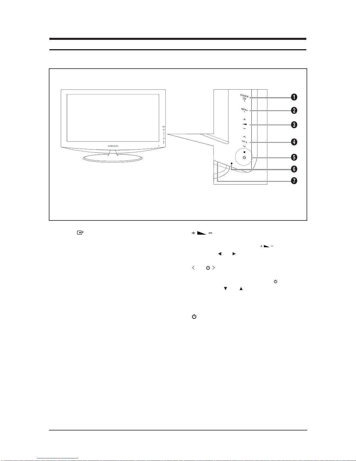
Front
1. SOURCE
Toggles between all the available input
sources (TV, Ext.1, Ext.2, AV, S-Video, Component,
PC, HDMI1, HDMI2, DTV). In the on-screen menu,
use this button as you use the ENTER/OK button on
the remote control. (LE23R86BD/LE26R86BD)
Toggles between all the available input sources
(TV, Ext.1, Ext.2, AV, S-Video, Component, PC,
HDMI1, HDMI2, HDMI3, DTV). In the on-screen
menu, use this button as you use the ENTER/OK
button on the remote control.
(LE32R86BD/LE37R86BD/LE40R86BD)
Toggles between all the available input sources
(TV, Ext.1, Ext.2, AV, S-Video, Component, PC,
HDMI1, HDMI2, HDMI3). In the on-screen menu,
use this button as you use the ENTER/OK button on
the remote control.
(LE32R81BX/LE37R81BX/LE40R81BX)
2. MENU
Press to see an on-screen menu of your TV's features.
In case of DTV mode, the DTV menu appears.
3.
Press to decrease or increase the volume.
In the on-screen menu, use the buttons as
you use the and buttons on the remote control.
4. C/P.
Press to change channels.
In the on-screen menu, use the < C/P. > buttons
as you use the and buttons on the remote
control. (Without the Remote Control, you can turn
on the TV by using the Channel buttons.)
5. (Power)
Press to turn the TV on and off.
Power Indicator
Blinks and turns off when the power is on and
lights up in stand-by mode.
6. Remote Control Sensor
Aim the remote control towards this spot on the TV.
7. Speakers
- The product color and shape may vary depending on the model.
Front Panel buttons
Touch the right side of each
button to operate.
10 Operating Instructions and Installation
10-2
10-2
LE23R86BD/LE26R86BD/LE32R86BD/LE37R86BD/LE40R86BD
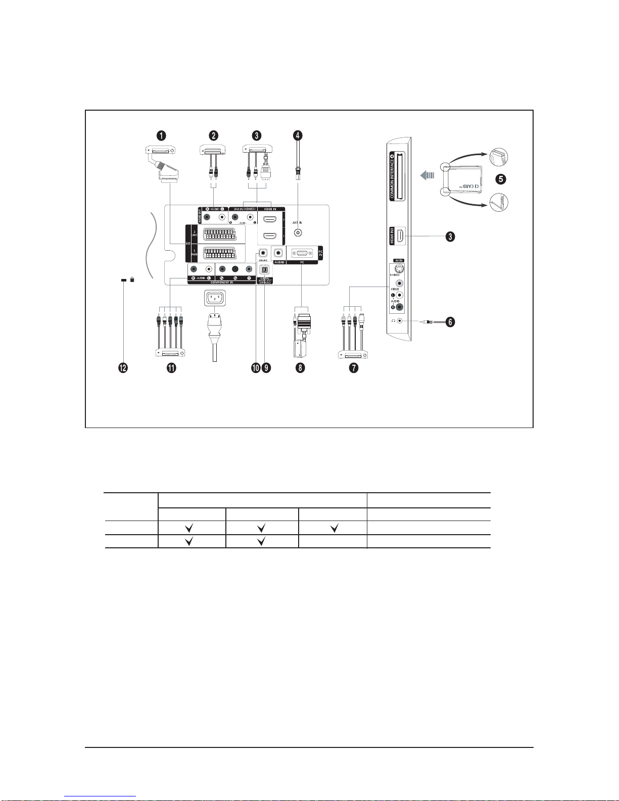
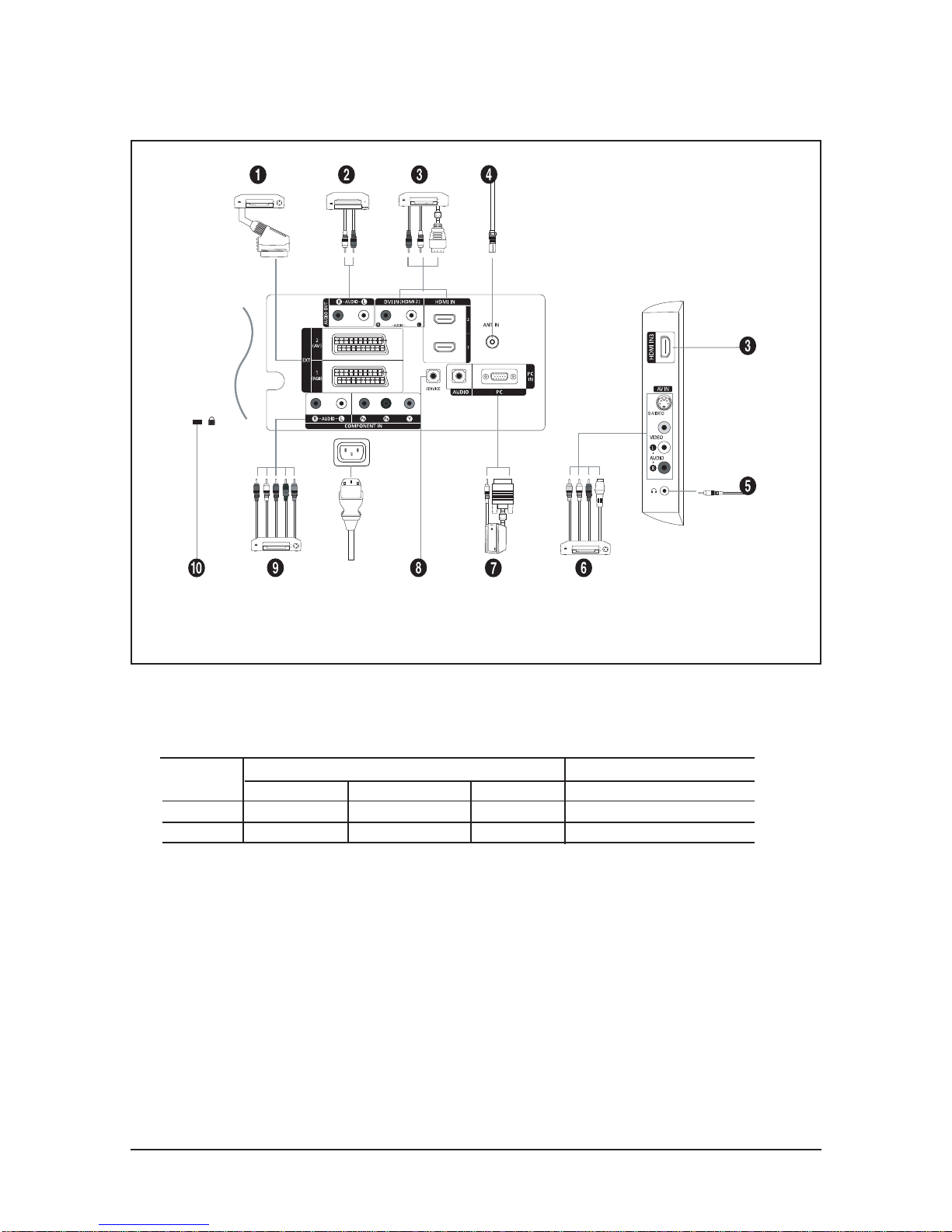
Viewing the Connection Panel
- Whenever you connect an external device to your TV, make sure that power on the unit is turned off.
- When connecting an external device, match the colour of the connection terminal to the cable.
- The product colour and shape may vary depending on the model.
1. Connecting Set-Top Box, VCR or DVD
- Inputs or outputs for external devices, such as VCR, DVD, video game device or video disc players.
2. Connecting AUDIO
- Connect RCA audio cables to "R - AUDIO - L" on the rear of your set and the other ends to corresponding audio
in connectors on the Amplifier or DVD Home Theater.
Connector
EXT 1
EXT 2
Output
Video + Audio (L/R)
Only TV or DTV output is available.
Output you can choose.
Input
Video Audio (L/R) RGB
Power Input
10 Operating Instructions and Installation
10-3
3. HDMI IN 1,HDMI IN 2, HDMI IN 3(Only LE32R86BD/LE37R86BD/LE40R86BD)
- Supports connections between HDMI-connection-enabled AV devices (Set-Top Boxes, DVD players, AV receivers
and digital TVs).
- No additional Audio connection is needed for an HDMI to HDMI connection.
▶ What is HDMI?
- "High Definition Multimedia interface" allows the transmission of high definition digital video data and
multiple channels of digital audio ( 5.1 channels).
-
The HDMI/DVI terminal supports DVI connection to an extended device with the appropriate cable (not supplied).
The difference between HDMI and DVI is that the HDMI device is smaller in size, has the HDCP (High Bandwidth Digital
Copy Protection) coding feature installed, and supports multi - channel digital audio.
DVI IN (HDMI 2) (AUDIO R/L)
- When connecting this product via HDMI or DVI to a Set Top Box, DVD Player or Games Console etc, make sure
that it has been set to a compatible video output mode as shown in the table below. Failure to observe this may
result in picture distortion, image breakup or no picture.
- When using an HDMI/DVI cable connection, it is only possible from the HDMI 2 terminal.
▶ You should use the DVI-to-HDMI cable or DVI-HDMI Adapter for the connection, and the "R - AUDIO - L"
terminal on DVI for sound output.
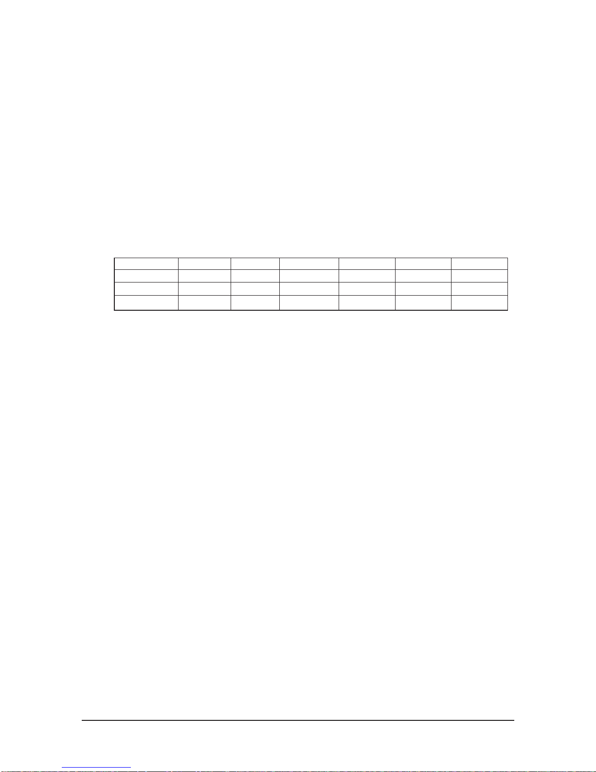
▶ Supported modes for HDMI/DVI and Component
4. Connecting an Aerial or Cable Television Network
To view television channels correctly, a signal must be received by the set from one of the following sources:
- An outdoor aerial / A cable television network / A satellite network
5. Connecting CI (Common Interface) CARD
- When not inserting "CI CARD" in some channels,"Scrambled Signal" is displayed on the screen.
- The pairing information containing a telephone number, CI CARD ID, Host ID and other information will be
displayed in about 2~3 minutes. If an error message is displayed, please contact your service provider.
- When the channel information configuration has finished, the message "Updating Completed" is displayed,
indicating that the channel list is now updated.
. You must obtain a CI CARD from a local cable service provider.
Remove the CI CARD by carefully pulling it out with your hands since dropping the CI CARD
may cause damage to it.
. Insert the CI-Card in the direction marked on it.
7. Connecting External A/V Devices
- Connect RCA or S-VIDEO cable to an appropriate external A/V device such as VCR, DVD or Camcorder.
- Connect RCA audio cables to "R - AUDIO - L" on the rear of your set and the other ends to corresponding audio
out connectors on the A/V device.
- Headphone may be connected to the headphone output ( 6 ) on the rear of your set. While the headphone is
connected, the sound from the built-in speakers will be disabled.
8. Connecting Computer
- Connect the D- Sub cable (optional) to "PC (PC IN)" on the rear of your set and the other end to the Video Card
of your computer.
- Connect the stereo audio cable (optional) to "AUDIO (PC IN)" on the rear of your set and the other end to "Audio
Out" of the sound card on your computer.
9. DIGITAL AUDIO OUT (OPTICAL)
- Connect to a Digital Audio Component.
10. SERVICE
- Service connection for qualified service engineer.
480i 480p 576i 576p 720p 1080i
HDMI/DVI 50Hz X X X O O O
HDMI/DVI 60Hz X O X X O O
Component O O O O O O

10 Operating Instructions and Installation
10-4
11. Connecting Component Devices (DTV/DVD)
- Connect component video cables (optional) to component connector ("P
R", "PB", "Y") on the rear of your set and
the other ends to corresponding component video out connectors on the DTV or DVD.
- If you wish to connect both the Set-Top Box and DTV (or DVD), you should connect the Set-Top Box to the DTV
(or DVD) and connect the DTV (or DVD) to component connector ("P
R", "PB", "Y") on your set.
- The PR, PB and Y connectors on your component devices (DTV or DVD) are sometimes labeled Y, B-Y and R-Y
or Y, Cb and Cr.
- Connect RCA audio cables (optional) to "R - AUDIO - L" on the rear of your set and the other ends to
corresponding audio out connectors on the DTV or DVD.
- This LCD TV displays its optimum picture resolution in 720p mode.
- This LCD TV displays its maximum picture resolution in 1 080i mode.
12. Kensington Lock
- The Kensington lock (optional) is a device used to physically fix the system when used in a public place.
- If you want to use a locking device, contact the dealer where you purchased the TV.
- The place of the Kensington Lock may be different depending on its model.
10 Operating Instructions and Installation
10-5
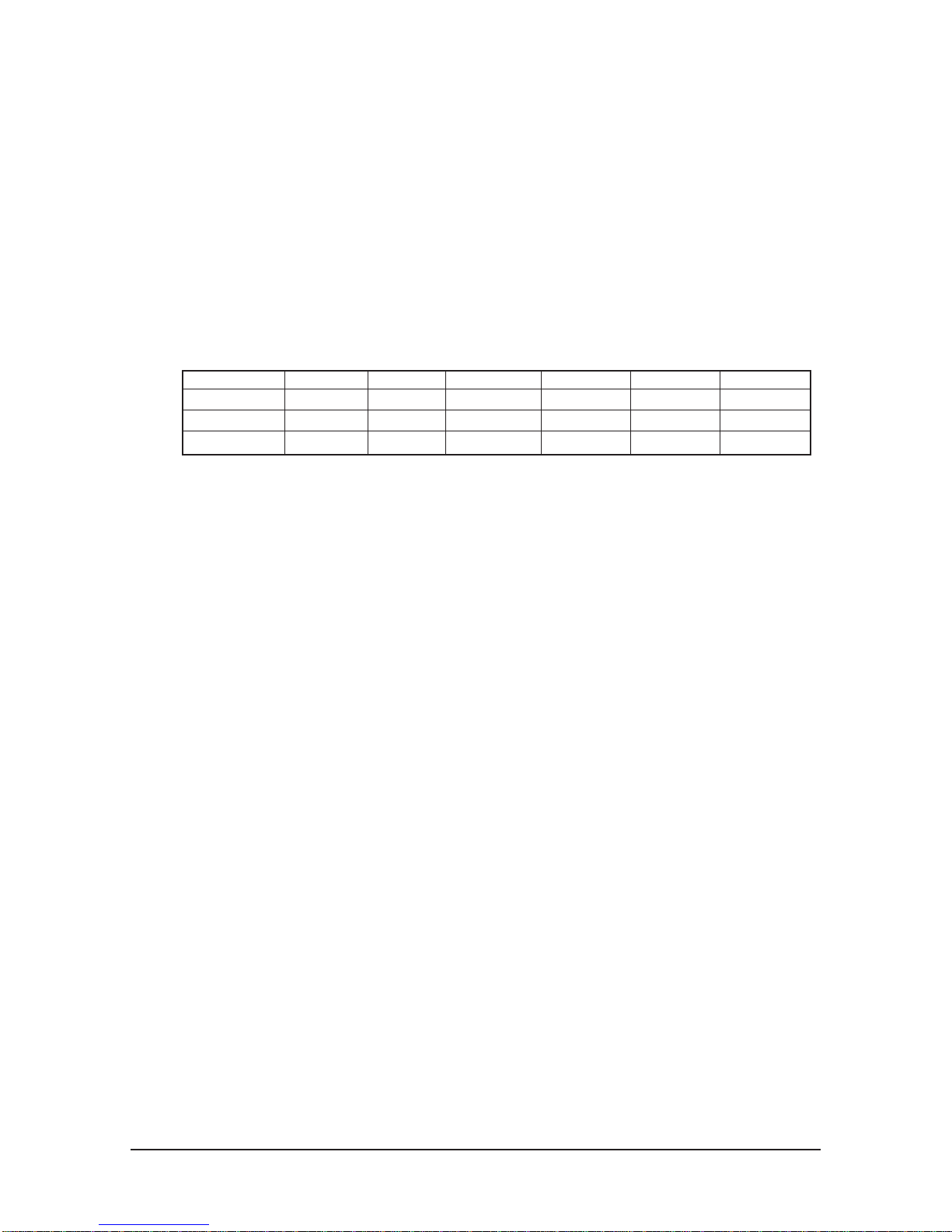
10-3
LE32R81BX/LE37R81BX/LE40R81BX Viewing the Connection Panel
- Whenever you connect an external device to your TV, make sure that power on the unit is turned off.
- When connecting an external device, match the colour of the connection terminal to the cable.
- The product colour and shape may vary depending on the model.
1. Connecting Set-Top Box, VCR or DVD
- Inputs or outputs for external devices, such as VCR, DVD, video game device or video disc players.
2. Connecting AUDIO
- Connect RCA audio cables to "R - AUDIO - L" on the rear of your set and the other ends to corresponding audio
in connectors on the Amplifier or DVD Home Theater.
Connector
EXT 1
EXT 2
Output
Video + Audio (L/R)
Only TV output is available.
Output you can choose.
Input
Video
O
O
Audio (L/R)
O
O
RGB
O
Power Input
10 Operating Instructions and Installation
10-6
3. HDMI IN 1,HDMI IN 2, HDMI IN 3
- Supports connections between HDMI-connection-enabled AV devices (Set-Top Boxes, DVD players, AV receivers
and digital TVs).
- No additional Audio connection is needed for an HDMI to HDMI connection.
▶ What is HDMI?
- "High Definition Multimedia interface" allows the transmission of high definition digital video data and
multiple channels of digital audio ( 5.1 channels).
-
The HDMI/DVI terminal supports DVI connection to an extended device with the appropriate cable (not supplied).
The difference between HDMI and DVI is that the HDMI device is smaller in size, has the HDCP (High Bandwidth Digital
Copy Protection) coding feature installed, and supports multi - channel digital audio.
DVI IN (HDMI 2) (AUDIO R/L)
- When connecting this product via HDMI or DVI to a Set Top Box, DVD Player or Games Console etc, make sure
that it has been set to a compatible video output mode as shown in the table below. Failure to observe this may
result in picture distortion, image breakup or no picture.
- When using an HDMI/DVI cable connection, it is only possible from the HDMI 2 terminal.
▶ You should use the DVI-to-HDMI cable or DVI-HDMI Adapter for the connection, and the "R - AUDIO - L"
terminal on DVI for sound output.
▶ Supported modes for HDMI/DVI and Component
4. Connecting an Aerial or Cable Television Network
To view television channels correctly, a signal must be received by the set from one of the following sources:
- An outdoor aerial / A cable television network / A satellite network
6. Connecting External A/V Devices
- Connect RCA or S-VIDEO cable to an appropriate external A/V device such as VCR, DVD or Camcorder.
- Connect RCA audio cables to "R - AUDIO - L" on the rear of your set and the other ends to corresponding audio
out connectors on the A/V device.
- Headphone may be connected to the headphone output ( 5 ) on the rear of your set. While the headphone is
connected, the sound from the built-in speakers will be disabled.
7. Connecting Computer
- Connect the D- Sub cable (optional) to "PC (PC IN)" on the rear of your set and the other end to the Video Card
of your computer.
- Connect the stereo audio cable (optional) to "AUDIO (PC IN)" on the rear of your set and the other end to "Audio
Out" of the sound card on your computer.
8. SERVICE
- Service connection for qualified service engineer.
9. Connecting Component Devices (DTV/DVD)
- Connect component video cables (optional) to component connector ("P
R", "PB", "Y") on the rear of
your set and the other ends to corresponding component video out connectors on the DTV or DVD.
- If you wish to connect both the Set-Top Box and DTV (or DVD), you should connect the Set-Top Box
to the DTV (or DVD) and connect the DTV (or DVD) to component connector ("P
R", "PB", "Y") on your set.
- The P
R, PB and Y connectors on your component devices (DTV or DVD) are sometimes labeled Y,
B-Y and R-Y or Y, Cb and Cr.
- Connect RCA audio cables (optional) to "R - AUDIO - L" on the rear of your set and the other ends
to corresponding audio out connectors on the DTV or DVD.
- This LCD TV displays its optimum picture resolution in 720p mode.
- This LCD TV displays its maximum picture resolution in 1080i mode.
10. Kensington Lock
- The Kensington lock (optional) is a device used to physically fix the system when used in a public place.
- If you want to use a locking device, contact the dealer where you purchased the TV.
- The place of the Kensington Lock may be different depending on its model.
480i 480p 576i 576p 720p 1080i
HDMI/DVI 50Hz X X X O O O
HDMI/DVI 60Hz X O X X O O
Component O O O O O O
10 Operating Instructions and Installation
10-7
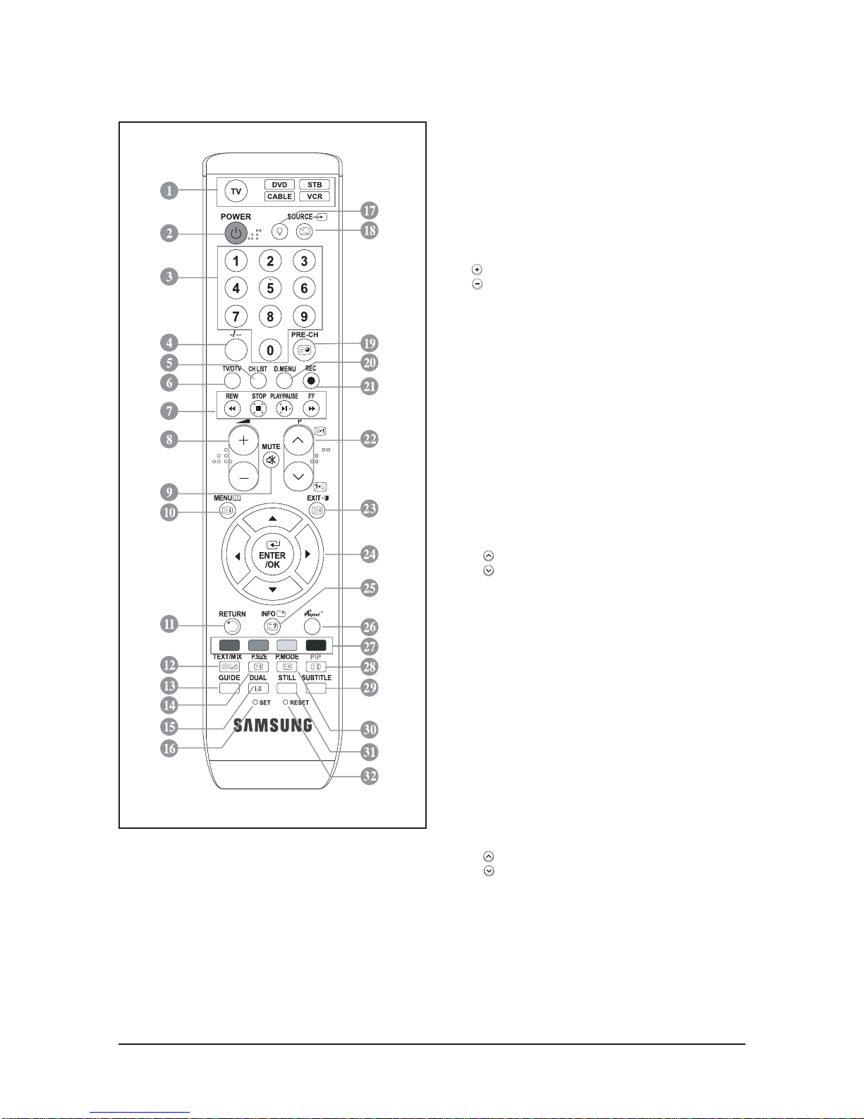
10-4
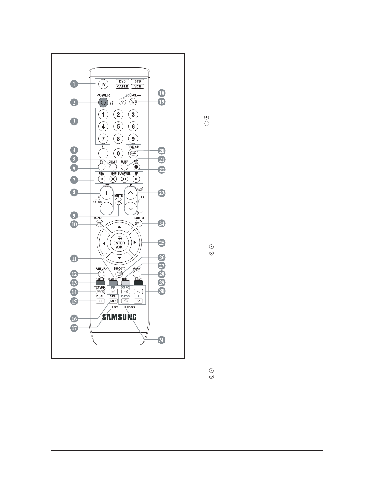
LE23R86BD/LE26R86BD Remote Control
1. Selects a target device to be controlled by the Samsung
remote control (TV, DVD, STB, CABLE, VCR)
2. Television Standby button
3. Number buttons for direct channel access
4. One/Two-digit channel selection
5. It display "Channel List" on the screen.
6. Selects the TV mode directly
7. VCR/DVD Functions
Rewind, Stop, Play/Pause,
Fast/Forward
8. Volume increase
Volume decrease
9. Temporary sound switch-off
10. Menu display and change confirmation
11. Returns to the previous menu
12. SRS TS XT selection
13. Electronic Program Guide (EPG) display
14. Picture size selection
15. Sound effect selection
16. Adjusts 5 separate devices - TV, DVD, STB, CABLE,
or VCR.
17. When pressing this button, a number of buttons on the
remote control (e.g. Selects a target device, volume,
channel and MUTE buttons) light up for a few seconds
and then turn off to save power. This function is to
conveniently use the remote control at night or when dark.
18. Available source selection
19. Previous channel
20. DTV menu display
21. Records for Live Broadcasting
22. P : Next channel
P : Previous channel
23. Exit the OSD
24. Control the cursor in the menu
25. Use to see information on the current broadcast
27. Colour buttons :
Press to add or delete channels and to store
channels to the favorite channel list in the
"Channel List" menu.
28. Picture-In-Picture On / Off
29. Digital subtitle display
30. Picture effect selection
31. Picture freeze
32. When your remote does not work, change the batteries
and press the "RESET" button for 2-3 seconds before use.
Teletext Functions
6. Exit from the teletext display
10. Teletext index
14. Teletext size selection
18. Teletext mode selection (LIST/FLOF)
19. Teletext sub page
22. P : Teletext next page
P : Teletext previous page
23. Teletext cancel
25. Teletext reveal
26. Alternately select Teletext, Double, or Mix.
27. Fastext topic selection
28. Teletext hold
30. Teletext store
▶ The performance of the remote control may be affected by bright light.
▶ This is a special remote control for the visually impaired, and has Braille points on the Power, Channel, STOP,
PLAY/PAUSE and Volume buttons.
10 Operating Instructions and Installation
10-8
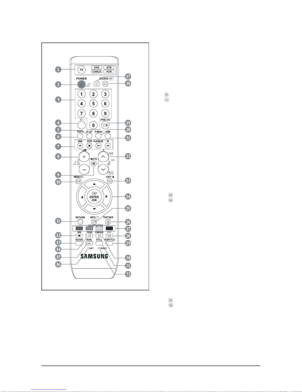
10-5
LE32R86BD/LE37R86BD/LE40R86BD Remote Control
1. Selects a target device to be controlled by the Samsung
remote control (TV, DVD, STB, CABLE, VCR)
2. Television Standby button
3. Number buttons for direct channel access
4. One/Two-digit channel selection
5. It display "Channel List" on the screen.
6. Selects the TV mode directly
7. VCR/DVD Functions
Rewind, Stop, Play/Pause,
Fast/Forward
8. Volume increase
Volume decrease
9. Temporary sound switch-off
10. Menu display and change confirmation
11. Returns to the previous menu
12. SRS TS XT selection
13. Electronic Program Guide (EPG) display
14. Picture size selection
15. Sound effect selection
16. Adjusts 5 separate devices - TV, DVD, STB, CABLE,
or VCR.
17. When pressing this button, a number of buttons on the
remote control (e.g. Selects a target device, volume,
channel and MUTE buttons) light up for a few seconds
and then turn off to save power. This function is to
conveniently use the remote control at night or when dark.
18. Available source selection
19. Previous channel
20. DTV menu display
21. Selects the HDMI mode directly.
22. P : Next channel
P : Previous channel
23. Exit the OSD
24. Control the cursor in the menu
25. Use to see information on the current broadcast
27. Colour buttons :
Press to add or delete channels and to store
channels to the favorite channel list in the
"Channel List" menu.
28. Picture-In-Picture On / Off
29. Digital subtitle display
30. Picture effect selection
31. Picture freeze
32. When your remote does not work, change the batteries
and press the "RESET" button for 2-3 seconds before use.
Teletext Functions
6. Exit from the teletext display
10. Teletext index
14. Teletext size selection
18. Teletext mode selection (LIST/FLOF)
19. Teletext sub page
22. P : Teletext next page
P : Teletext previous page
23. Teletext cancel
25. Teletext reveal
26. Alternately select Teletext, Double, or Mix.
27. Fastext topic selection
28. Teletext hold
30. Teletext store
▶ The performance of the remote control may be affected by bright light.
▶ This is a special remote control for the visually impaired, and has Braille points on the Power, Channel, STOP,
PLAY/PAUSE and Volume buttons.
10 Operating Instructions and Installation
10-9
10-6
LE32R81BX/LE37R81BX/LE40R81BX Remote Control
1. Selects a target device to be controlled by the Samsung
remote control (TV, DVD, STB, CABLE, VCR)
2. Television Standby button
3. Number buttons for direct channel access
4. One/Two-digit channel selection
5. It display "Channel List" on the screen.
6. Selects the TV mode directly
7. VCR/DVD Functions
Rewind, Stop, Play/Pause,
Fast/Forward
8. Volume increase
Volume decrease
9. Temporary sound switch-off
10. Menu display and change confirmation
11. Returns to the previous menu
12. Returns to the previous menu
13. Picture effect selection
15. Sound effect selection
16. SRS TS XT selection
17. Adjusts 5 separate devices -TV, DVD, STB, CABLE,
or VCR.
18. When pressing this button, a number of buttons on the
remote control (e.g. Selects a target device, volume,
channel and MUTE buttons) light up for a few seconds
and then turn off to save power. This function is to
conveniently use the remote control at night or when dark.
19. Available source selection
20. Previous channel
20. DTV menu display
21. Automatic Power-off
22. Records for Live (Anynet+ function only)
23. P : Next channel
P : Previous channel
24. Exit the OSD
25. Control the cursor in the menu
26. Use to see information on the current broadcast
27. Picture size selection
28. Runs the Anynet view functions and sets up Anynet
devices. Please refer to the Anynet Owner's Instruction.
29. Picture size selection
30. PIP:Picture-In-Picture On/Off
SOURCE: Input source selection
POSITION: PIP position selection
31. When your remote does not work, change the batteries
and press the "RESET" button for 2-3 seconds before use.
Teletext Functions
6. Exit from the teletext display
10. Teletext index
14. Alternately select Teletext, Double, or Mix.
19. Teletext mode selection (LIST/FLOF)
20. Teletext sub page
23. P : Teletext next page
P : Teletext previous page
24. Teletext cancel
26. Teletext reveal
11, 13, 27,29 Fastext topic selection
30. PIP:Teletext Hold
30. SOURCE: Teletext Store
30. POSITION: Teletext size selection
▶ The performance of the remote control may be affected by bright light.
▶ This is a special remote control for the visually impaired, and has Braille points on the Power, Channel, STOP,
PLAY/PAUSE and Volume buttons.
10 Operating Instructions and Installation
10-10
10-7 Installing the Stand
1. Place the TV faced down on a soft cloth or cushion on a table.
2. Put the stand into the hole at the bottom of the TV.
3. Insert screw into the hole indicated and tighten.
▶ The stand is installed for models with the screen size of 37 inch and above.
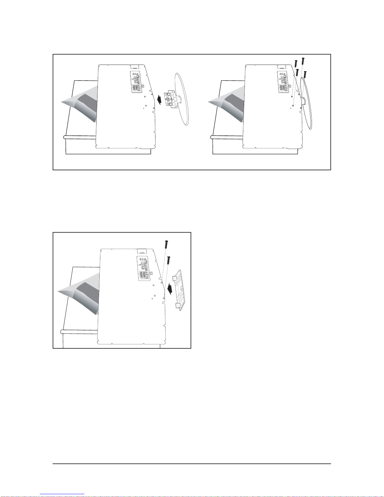
10-8 Installing the Wall Mount Kit
Wall mount items (sold separately) allow you to mount the TV on the wall.
For detailed information on installing the wall mount, see the instructions provided with the Wall Mount
items. Contact a technician for assistance when installing the wall mounted bracket.
Samsung Electronics is not responsible for any damage to the product or injury to yourself or others if you
elect to install the TV on your own.
▶ Remove the stand and cover the bottom hole with a cap and fasten with two screws.
< 2 > < 3 >
11 Disassembly and Reassembly
11-1
11 Disassembly and Reassembly
This section of the service manual describes the disassembly and reassembly procedures for the TFT-LCD
TV.
WARNING : This monitor contains electrostatically sensitive devices. Use caution when
handling these components.
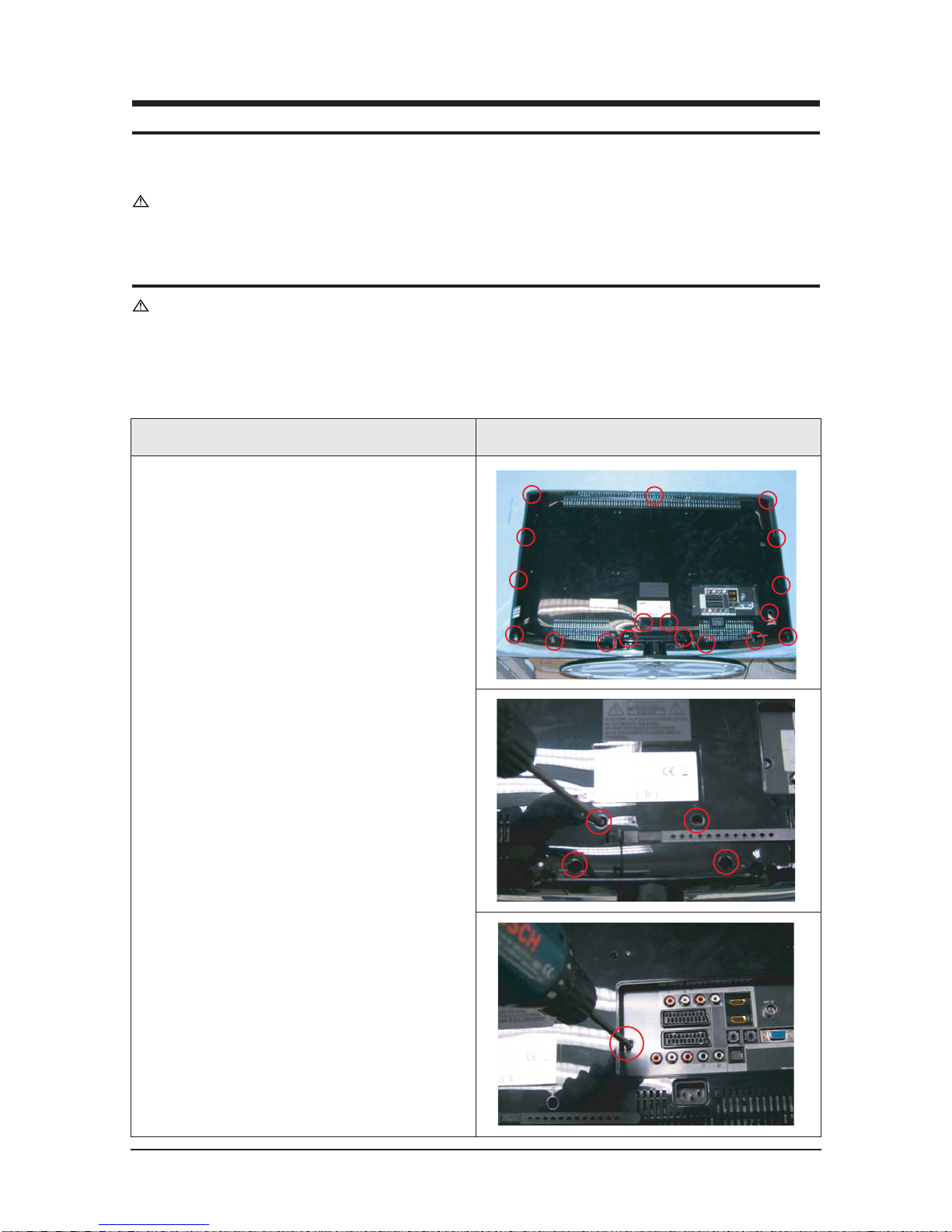
11-1 Disassembly
Cautions : 1. Disconnect the monitor from the power source before disassembly.
2. Follow these directions carefully; never use metal instruments to pry apart the
cabinet.
Description Picture Description
1. Place monitor face down on cushioned table.
Remove screws from the rear cover and
remove screws from the stand.
11 Disassembly and Reassembly
11-2
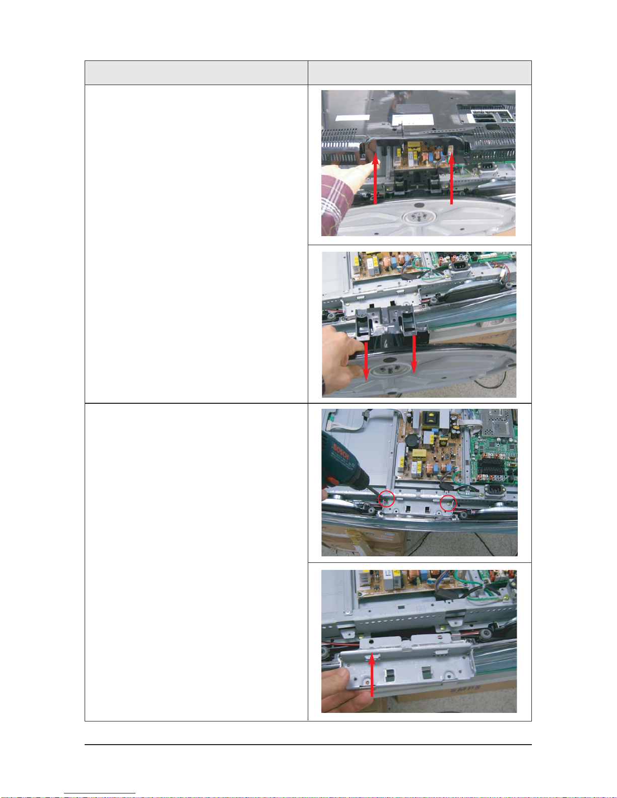
3. Remove Screws from the stand BRKT and lift
up the stand BRKT.
Description Picture Description
2. Lift up the rear cover and remove the stand.

11 Disassembly and Reassembly
11-3
5. Remove screws from the boards and remove
screw from theside connector.
(only for CIS)
(only for CIS)
Description Picture Description
4. Lift up the shield and disonnect cables from
the boards.

11 Disassembly and Reassembly
11-4
Description Picture Description
6. Remove screws and lift up the BRKT

11 Disassembly and Reassembly
11-5
11-2 Reassembly
Reassembly procedures are in the reverse order of disassembly procedures.

11 Disassembly and Reassembly
11-6
Memo
12 PCB Diagram
12-1
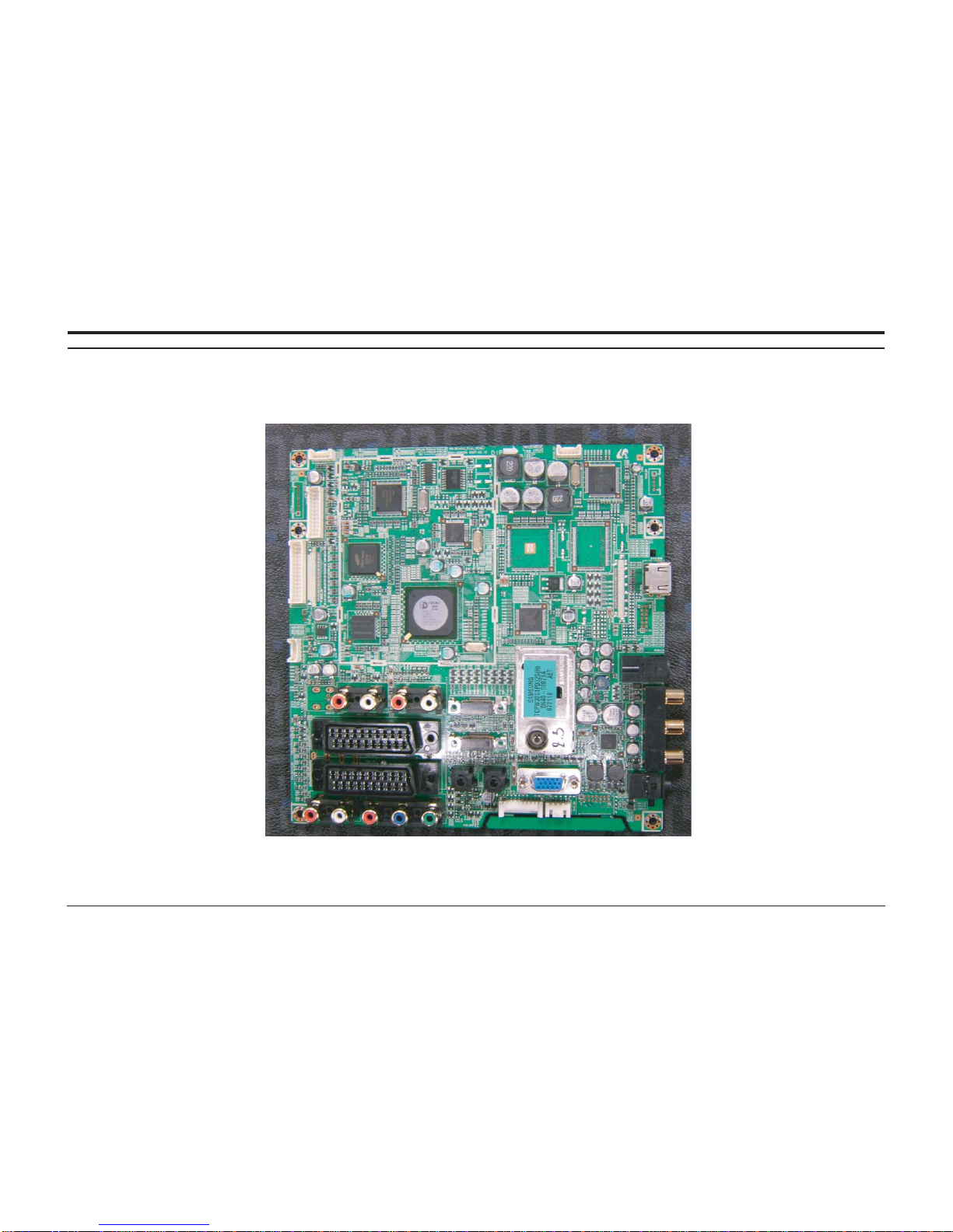
12 PCB Diagram
12-1 Main PCB Diagram (FOR READY)
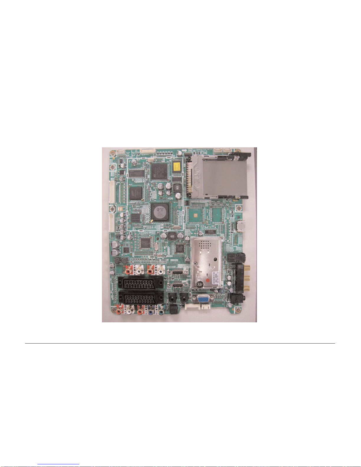
12 PCB Diagram
12-2
12-2 Main PCB Diagram (FOR IDTV)
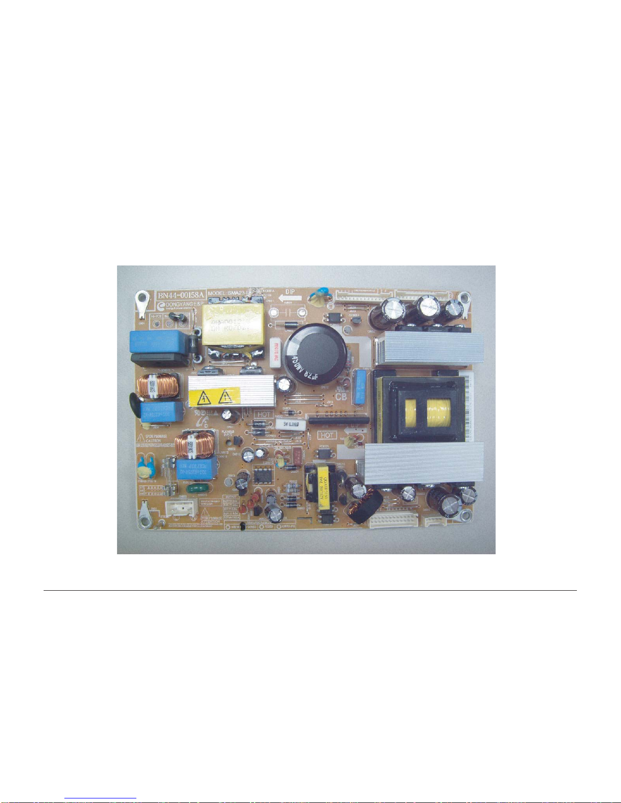
12 PCB Diagram
12-3
12-3 23" SMPS
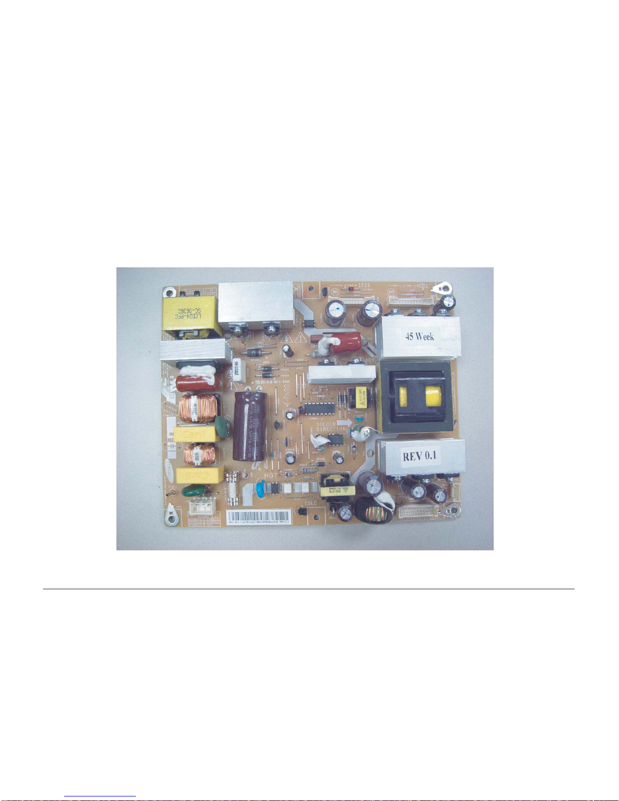
12 PCB Diagram
12-4
12-4 26", 32" SMPS

12 PCB Diagram
12-5
12-5 37" SMPS
 Loading...