

Page 1
LCD-TV
Chassis : N82C
Model : LE19C35***
SERVICE
LE22C35***
Manual
TFT-LCD TV Contents
1. Precautions
2. Product specications
3. Disassembly and Reassembly
4. Troubleshooting
5. Exploded View & Part List
6. Wiring Diagram
LE19C35*** / LE22C35***
Refer to the service manual in the GSPN (see the rear cover) for the more information.
Page 2

Contents
1. Precautions .............................................................................................................. 1-1
1-1. Safety Precautions ......................................................................................................... 1-1
1-2. Servicing Precautions .....................................................................................................1-2
1-3. Electrostatically Sensitive Devices (ESD) Precautions .................................................. 1-2
1-4. Installation Precautions .................................................................................................. 1-3
2. Product specications ............................................................................................ 2-1
2-1. Feature & Specications ................................................................................................. 2-1
2-2. Specication Comparison to Old Models ........................................................................ 2-3
2-3. Detail Factory Option ...................................................................................................... 2-4
2-4. Accessories .................................................................................................................... 2-8
3. Disassembly and Reassembly ............................................................................... 3-1
3-1. Disassembly and Reassembly ....................................................................................... 3-1
4. Troubleshooting ...................................................................................................... 4-1
4-1. Troubleshooting .............................................................................................................. 4-1
4-2. Alignments and Adjustments ........................................................................................ 4-25
4-3. Factory Mode Adjustments ........................................................................................... 4-26
4-4. White Balance - Calibration .......................................................................................... 4-34
4-5. White Ratio (Balance) Adjustment ................................................................................ 4-34
4-6. Servicing Information .................................................................................................... 4-35
4-7. How To Upgrade Sub Micom With Ddc Manager ......................................................... 4-36
4-8. Mechanical diagram ..................................................................................................... 4-38
4-9. PCB diagram ................................................................................................................ 4-39
5. Exploded View & Part List ...................................................................................... 5-1
5-1. Exploded View ................................................................................................................ 5-1
5-2. Parts List ......................................................................................................................... 5-3
6. Wiring Diagram ........................................................................................................ 6-1
6-1. Wiring Diagram ............................................................................................................... 6-1
6-2. Connector ....................................................................................................................... 6-3
6-3. Connector Functions ...................................................................................................... 6-4
6-4. Cables ............................................................................................................................ 6-4
Page 3
GSPN (Global Service Partner Network)
Area Web Site
North America http://service.samsungportal.com
Latin America http://latin.samsungportal.com
CIS http://cis.samsungportal.com
Europe http://europe.samsungportal.com
China http://china.samsungportal.com
Asia http://asia.samsungportal.com
Mideast & Africa http://mea.samsungportal.com
This Service Manual is a property of Samsung Electronics Co.,Ltd.
Any unauthorized use of Manual can be punished under applicable
International and/or domestic law.
© 2010 Samsung Electronics Co.,Ltd.
All rights reserved.
Printed in Korea
P/N: BN82-00930A-00
Page 4
1. Precautions
1. Precautions
1-1. Safety Precautions
Follow these safety, servicing, and ESD precautions to prevent damage and to protect against potential hazards such as
electrical shock.
1-1-1. Warnings
For continued safety, do not attempt to modify any circuitry.1.
1-1-2. Servicing the LCD TV
When servicing the LCD TV, Disconnect the AC line cord from the AC outlet.1.
It is essential that service technicians have an accurate voltage meter available at all times. 2.
Check the calibration of this meter periodically.
1-1-3. Fire and Shock Hazard
Before returning the LCD TV to the user, perform the following safety checks:
Inspect each lead dress to make certain that the leads are not pinched or that hardware is not lodged between the 1.
chassis and other metal parts in the LCD TV.
Inspect all protective devices such as nonmetallic control knobs, insulating materials, cabinet backs, adjustment and 2.
compartment covers or shields, isolation resistor capacitor networks, mechanical insulators, etc.
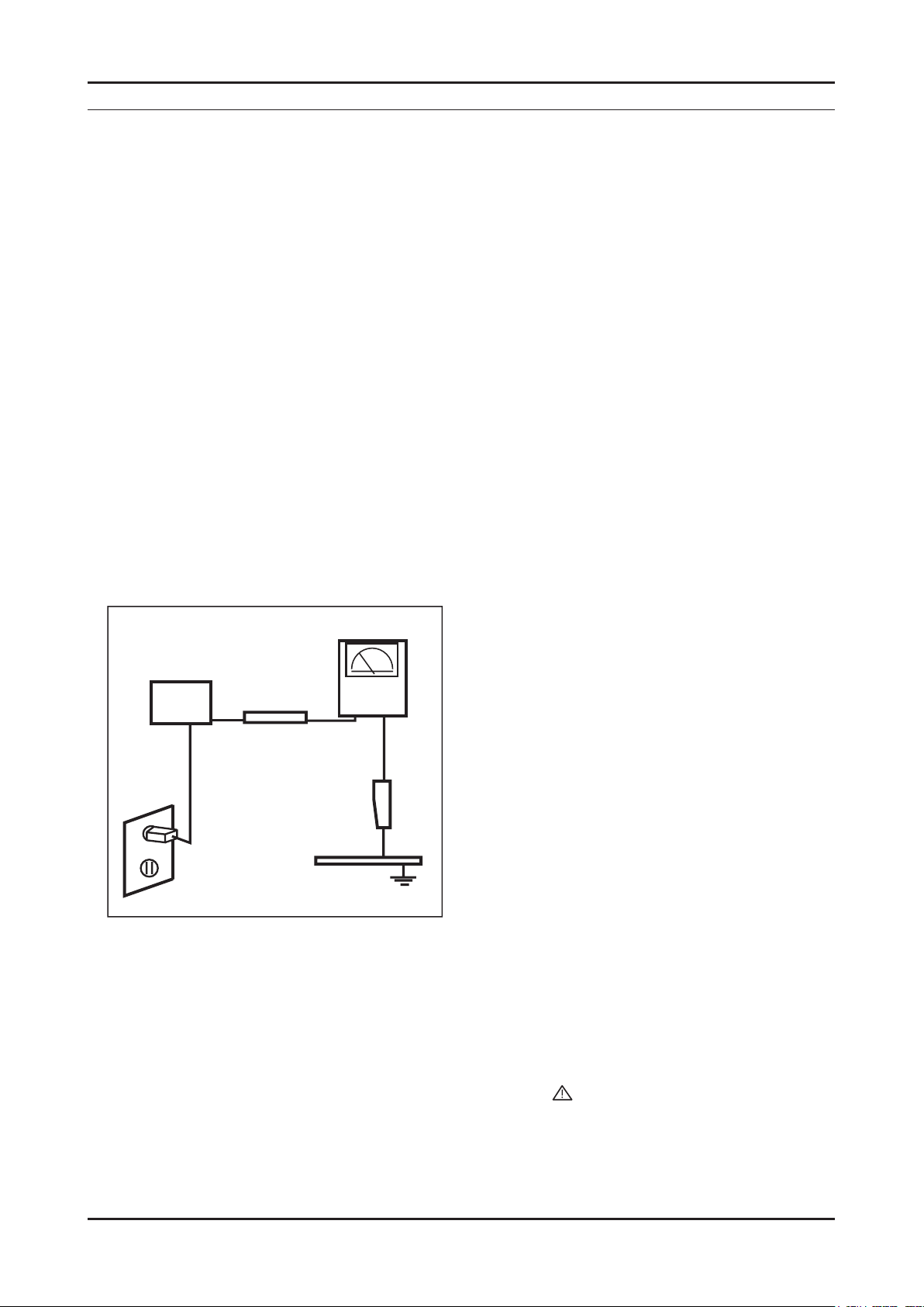
Leakage Current Hot Check (Figure 1-1): 3.
WARNING : Do not use an isolation transformer during this test.
Use a leakage current tester or a metering system that complies with American National Standards Institute (ANSI
C101.1, Leakage Current for Appliances), and Underwriters Laboratories (UL Publication UL1410, 59.7).
With the unit completely reassembled, plug the AC line cord directly into a 120V AC outlet. With the unit’s AC switch 4.
(READING SHOULD)
NOT BE ABOVE 0.5mA
DEVICE
UNDER
TEST
2-WIRE CORD
*ALSO TEST WITH
PLUG REVERSED
(USING AC ADAPTER
PLUG AS REQUIRED)
TEST ALL
EXPOSED METAL
SURFACES
LEAKAGE
CURRENT
TESTER
EARTH
GROUND
Figure 1-1. Leakage Current Test Circuit
rst in the ON position and then OFF, measure the current between a known earth ground (metal water pipe, conduit,
etc.) and all exposed metal parts, including: metal cabinets, screwheads and control shafts.
The current measured should not exceed 0.5 milliamp.
Reverse the power-plug prongs in the AC outlet and repeat the test.
1-1-4. Product Safety Notices
Some electrical and mechanical parts have special safety related characteristics which are often not evident from visual
inspection. The protection they give may not be obtained by replacing them with components rated for higher voltage,
wattage, etc. Parts that have special safety characteristics are identied by on schematics and parts lists. A substitute
replacement that does not have the same safety characteristics as the recommended replacement part might create
shock, re and/or other hazards. Product safety is under review continuously and new instructions are issued whenever
appropriate.
1-1
Page 5

1-2
1. Precautions
1-2. Servicing Precautions
WARNING: An electrolytic capacitor installed with the wrong polarity might explode.
Caution: Before servicing units covered by this service manual, read and follow the Safety Precautions section of
this manual.
Note: If unforeseen circumstances create conict between the following servicing precautions and any of the
safety precautions, always follow the safety precautions.
1-2-1 General Servicing Precautions
Always unplug the unit’s AC power cord from the AC power source and disconnect the DC Power Jack before 1.
attempting to:
(a) remove or reinstall any component or assembly, (b) disconnect PCB plugs or connectors, (c) connect a test
component in parallel with an electrolytic capacitor.
Some components are raised above the printed circuit board for safety. An insulation tube or tape is sometimes 2.
used. The internal wiring is sometimes clamped to prevent contact with thermally hot components. Reinstall all such
elements to their original position.
After servicing, always check that the screws, components and wiring have been correctly reinstalled. Make sure that 3.
the area around the serviced part has not been damaged.
Check the insulation between the blades of the AC plug and accessible conductive parts (examples: metal panels, 4.
input terminals and earphone jacks).
Insulation Checking Procedure: Disconnect the power cord from the AC source and turn the power switch ON. 5.
Connect an insulation resistance meter (500 V) to the blades of the AC plug. The insulation resistance between each
blade of the AC plug and accessible conductive parts (see above) should be greater than 1 mega ohm.
Always connect a test instrument’s ground lead to the instrument chassis ground before connecting the positive lead; 6.
always remove the instrument’s ground lead last.
1-3. Electrostatically Sensitive Devices (ESD) Precautions
Some semiconductor (solid state) devices can be easily damaged by static electricity. Such components are commonly
called Electrostatically Sensitive Devices (ESD). Examples of typical ESD are integrated circuits and some eld-effect
transistors. The following techniques will reduce the incidence of component damage caused by static electricity.
Immediately before handling any semiconductor components or assemblies, drain the electrostatic charge from your 1.
body by touching a known earth ground. Alternatively, wear a discharging wrist-strap device. To avoid a shock hazard,
be sure to remove the wrist strap before applying power to the LCD TV.
After removing an ESD-equipped assembly, place it on a conductive surface such as aluminum foil to prevent 2.
accumulation of an electrostatic charge.
Do not use freon-propelled chemicals. These can generate electrical charges sufcient to damage ESDs.3.
Use only a grounded-tip soldering iron to solder or desolder ESDs.4.
Use only an anti-static solder removal device. Some solder removal devices not classied as “anti-static” can generate 5.
electrical charges sufcient to damage ESDs.
Do not remove a replacement ESD from its protective package until you are ready to install it. Most replacement ESDs 6.
are packaged with leads that are electrically shorted together by conductive foam, aluminum foil or other conductive
materials.
Immediately before removing the protective material from the leads of a replacement ESD, touch the protective 7.
material to the chassis or circuit assembly into which the device will be installed.
Caution: Be sure no power is applied to the chassis or circuit and observe all other safety precautions.
Minimize body motions when handling unpackaged replacement ESDs. Motions such as brushing clothes together, 8.
or lifting your foot from a carpeted oor can generate enough static electricity to damage an ESD.
Page 6

1-3
1. Precautions
1-4. Installation Precautions
For safety reasons, more than a people are required for carrying the product.1.
Keep the power cord away from any heat emitting devices, as a melted covering may cause re or electric shock.2.
Do not place the product in areas with poor ventilation such as a bookshelf or closet. The increased internal 3.
temperature may cause re.
Bend the external antenna cable when connecting it to the product. This is a measure to protect it from being exposed 4.
to moisture. Otherwise, it may cause a re or electric shock.
Make sure to turn the power off and unplug the power cord from the outlet before repositioning the product. Also check 5.
the antenna cable or the external connectors if they are fully unplugged. Damage to the cord may cause re or electric
shock.
Keep the antenna far away from any high-voltage cables and install it rmly. Contact with the high-voltage cable or the 6.
antenna falling over may cause re or electric shock.
When installing the product, leave enough space (4 in) between the product and the wall for ventilation purposes. 7.
A rise in temperature within the product may cause re.
Page 7

1. Precautions
MEMO
1-4
Page 8
2. Product specications
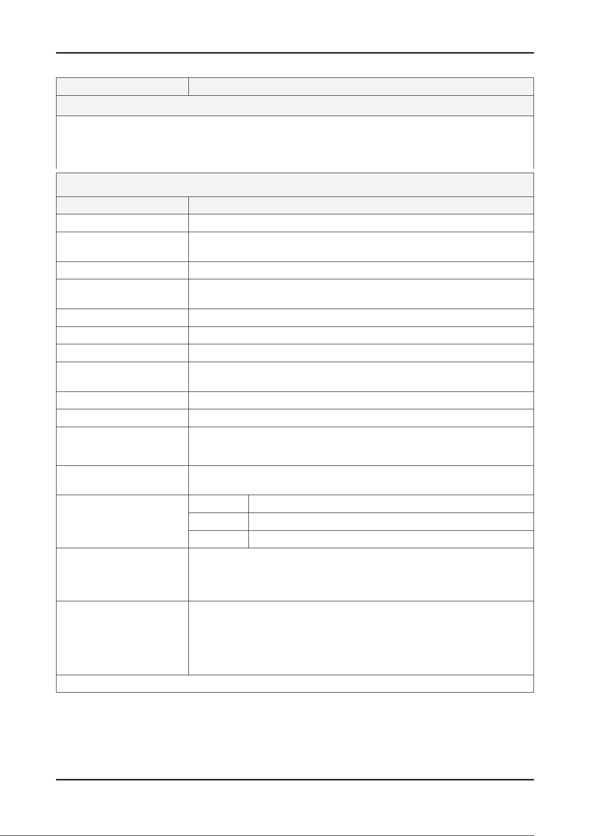
2-1. Feature & Specications
Model LE19C35***
2. Product specications
Feature
DIGITAL-TV, RF, 1-HDMI, 1-COMPONENT, 1-A/V, D-SUB, 1-SCART ሪ
Brightness : 250cd/m ሪ
Contrast Ratio : 1,000:1 ሪ
Response time : 5ms ሪ
Item Description
LCD Panel TFT-LCD Panel, RGB Vertical Stripe, Normally white, TN
Scanning Frequency Horizontal : 34KHz ~ 70KHz (Automatic)
Display Colors 16.7M color
Maximum resolution Horizontal : 1366 Pixels
Input Signal Analog 0.7 Vp-p ± 5% positive at 75Ω , internally terminated
Input Sync Signal H/V Separate, TTL, P. or N.
Maximum Pixel Clock rate 95.6MHz
Active Display
Horizontal/Vertical 16.13 x 9.07 inches (409.8(H) x 230.4 (V) mm)
AC power voltage & Frequency AC 110V ~ 240 @ 50/60 Hz
2
Specications
Vertical : 50Hz ~ 76Hz (Automatic)
Vertical : 768 Pixels
Power Consumption Under 35W (Under 1W , Stand by)
Dimensions
Set (W x D x H)
Weight (Set) 9.03 lbs (4.1 Kg)_with stand
TV System Tuning Frequency Synthesize (Refer to detailed Frequency Table)
Environmental Considerations Operating Temperature : 50˚F ~ 104˚F (10˚C ~ 40˚C)
Audio Spec. - MAX Internal Audio Output Power : Each 3W(Left/Right)
Note: DNSe, Game Mode, Energy Saving
18.16 x 7.09 x 13.7 inches (461.3 x 180.2 x 348.0 mm)_with stand
18.16 x 2.54 x 12.69 inches (461.2 x 64.4 x 322.2 mm)_without stand
8.59 lbs (3.9 Kg)_without stand
System PAL/SECAM, DVB-T
Sound MONO, STEREO, NICAM, MPEG, DD, DD+, HE-AAC
Operating Humidity : 10% ~ 80%, non-condensing
Storage temperature : -13˚F ~ 113˚F (-25˚C ~ 45˚C)
Storage Humidity : 5% ~ 95%, non-condensing
- BASS Control Range : -8 dB ~ + 8dB
- TREBLE Control Range : -8 dB ~ +8 dB
- Headphone Out : 10 mW MAX
- Output Frequency : RF : 80 Hz ~ 15 kHz
A/V : 80 Hz ~ 20 kHz
2-1
Page 9
2-2
2. Product specications
Model LE22B35***
Feature
DIGITAL-TV, RF, 1-HDMI, 1-COMPONENT, 1-A/V, D-SUB, 1-SCART ሪ
Brightness : 300cd/m ሪ
2
Contrast Ratio : 800:1 ሪ
Response time : 5ms ሪ
Specications
Item Description
LCD Panel TFT-LCD Panel, RGB Vertical Stripe, Normally white, TN
Scanning Frequency Horizontal : 30 KHz ~ 60 KHz (Automatic)
Vertical : 57 Hz ~ 63 Hz (Automatic)
Display Colors 16.7M color
Maximum resolution Horizontal : 1366 Pixels
Vertical : 768 Pixels
Input Signal Analog 0.7 Vp-p ± 5% positive at 75Ω , internally terminated
Input Sync Signal H/V Separate, TTL, P. or N.
Maximum Pixel Clock rate 82MHz
Active Display
Horizontal/Vertical 18.80 x 10.57 inches (477.42(H) x 268.42(V) mm)
AC power voltage & Frequency AC 110V ~ 240 @ 50/60 Hz
Power Consumption Under 55W (Under 1W , Stand by)
Dimensions
Set (W x D x H)
21.07 x 6.76 x 16.57 inches (535.3 x 171.8 x 420.9 mm)_with stand
21.07 x 3.37 x 14.40 inches (535.3 x 85.5 x 365.8 mm)_without stand
Weight (Set) 9.25 lbs (4.2 Kg)_with stand
8.58 lbs (3.9 Kg)_without stand
TV System Tuning Frequency Synthesize (Refer to detailed Frequency Table)
System PAL/SECAM, DVB-T
Sound MONO, STEREO, NICAM, MPEG, DD, DD+, HE-AAC
Environmental Considerations Operating Temperature : 50˚F ~ 104˚F (10˚C ~ 40˚C)
Operating Humidity : 10% ~ 80%, non-condensing
Storage temperature : -13˚F ~ 113˚F (-25˚C ~ 45˚C)
Storage Humidity : 5% ~ 95%, non-condensing
Audio Spec. - MAX Internal Audio Output Power : Each 3W(Left/Right)
- BASS Control Range : -8 dB ~ + 8dB
- TREBLE Control Range : -8 dB ~ +8 dB
- Headphone Out : 10 mW MAX
- Output Frequency : RF : 80 Hz ~ 15 kHz
A/V : 80 Hz ~ 20 kHz
Note: DNSe, Game Mode, Energy Saving
Page 10
2-3
2. Product specications
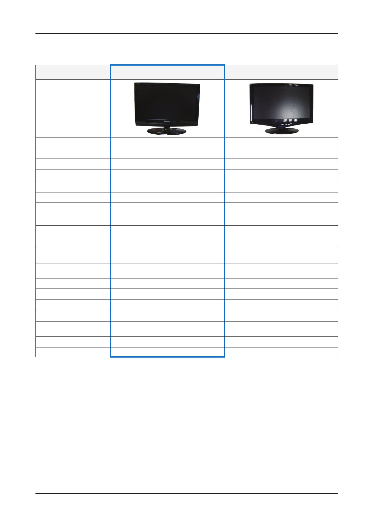
2-2. Specication Comparison to Old Models
O : application, X : non-application ※
Model LC3D (LE19/22C35***) LC3D(LE19/22C35***)
Design
Display Type LCD TV LCD TV
Built-in Tuner O O
Resolution 1360 x 768 1366 x 768
LCD Panel TFT LCD Panel 50Hz TFT LCD Panel 50Hz
Screen Size 19" / 22" 22"
Picture ratio 16 : 9 16 : 9
Dimensions (W x H x D)
Weight
Brightness
Contrast Ratio
Picture Enhacer DNIe(SETD-10) DNIe (Saturn4)
Equalizer O O
Auto Volume Control O O
Surround Sound Virtural Surround SRS TruSurround XT
Speaker Output 3W + 3W 3W + 3W
Energy Saving O O
Antenna 1(Cable/Air) 1(Cable/Air)
19 18.16 x 6.34 x 14.33 inches_with stand
22 21.07 x 6.76 x 16.57 inches_with stand
19 9.03 lbs_with stand
22 9.25 lbs_with stand
19" : 250 cd/m
22" : 300 cd/m
19" : 1,000:1
22" : 800:1
2
2
22 21.95 x 16.73 x 7.98 inches_with stand
22 8.82 lbs_with stand
300 cd/m
2
800 : 1
Page 11
2-4
2. Product specications
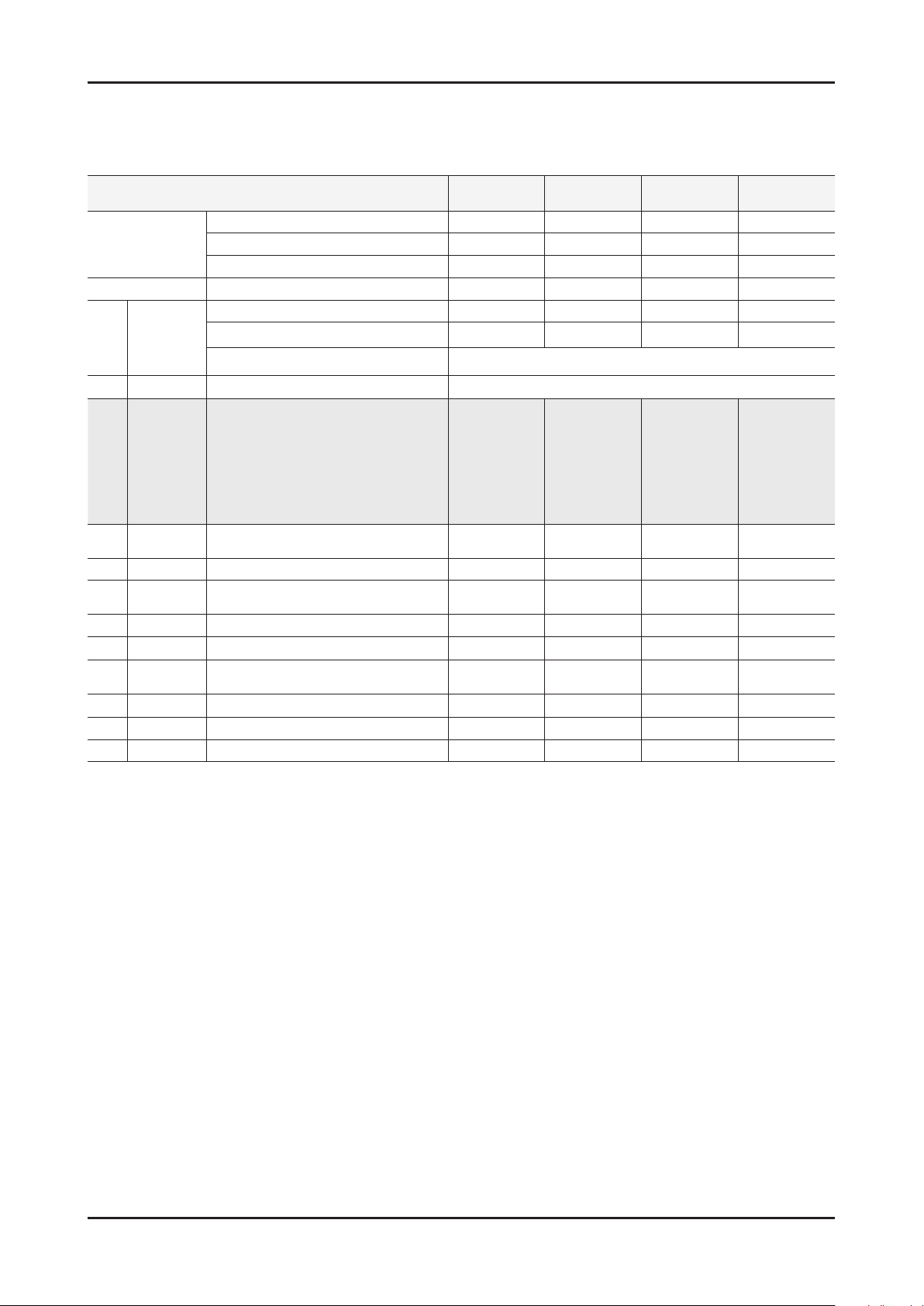
2-3. Detail Factory Option
If you replace the main board with new one, please change the factory option as well. ※
The options you must change are “Type”.
Model Name LE19C35*** LE19C35*** LE19C35*** LE22C35***
Vendor INNOL CPT AML CHILIN
Panel
SMPS Vendor FSP FSP SEMCO AMBIT
Byte Item
1 Factory Reset -
19D6THOC/19I6THOC/22D6THOC/
22L6THOC/22I6THOC/26D6THOC/
26L6AHOC/32A6AHOC/32L6AHOC/
2 Type
3 Local set
4 Model LC350/LC450/LC530/LC550/LC650 LC350 LC350 LC350 LC350
5 TUNER
6 DDR 0/1/2 0 0 0 0
7 Light Effect On/Off Off Off Off Off
8 Ch Table
9 Country - - - - -
10 PDP GROUP P43A_42Sn **** **** **** ****
11 Front Color
32D6AHOC/37L6AHOC/37I6AHOC/
40L6AHOC/32A6AFOC/32L6AFOC/
32D6AFOC/37L6AFOC/37D6AFOC/
40A6AFOC/40L6AFOC/40D6AFOC/
46A6AFOC/46L6AFOC/46D6AFOC/
EU/EU_ITALY/EU_AFRICA/EU_LSRAEL
DRXKXEMCO/S2SEMCO/T2CXD/DRXKSEM_E
DRXKAALPS/DRXKSEM_2
SUWON/SESK/SHE/TTSEC/SDMA/
SERK/SEIN/SAVINA/SIEL/TSE/s
CODE BN07-00766A BN07-00623A BN07-00703A BN07-00744A
SPEC MT185GW01 V2 CLAA185WA03 LTM185AT01-V T216HA01-DB
CODE BN44-00328B BN44-00328B BN44-00328A BN44-00366B
SPEC FSP035-2PI10 FSP035-2PI10 PSIV350310A K02P140.00
Adjustment Range
1906THOC 19I6THOC 19A6TH0C 22P6THOC
52A6AFOC/52L6AFOC/
/NORDIG/AD_Au/CIS
EU EU EU EU
DRXKXEMCO DRXKXEMCO DRXKXEMCO DRXKXEMCO
Page 12
2-5
2. Product specications
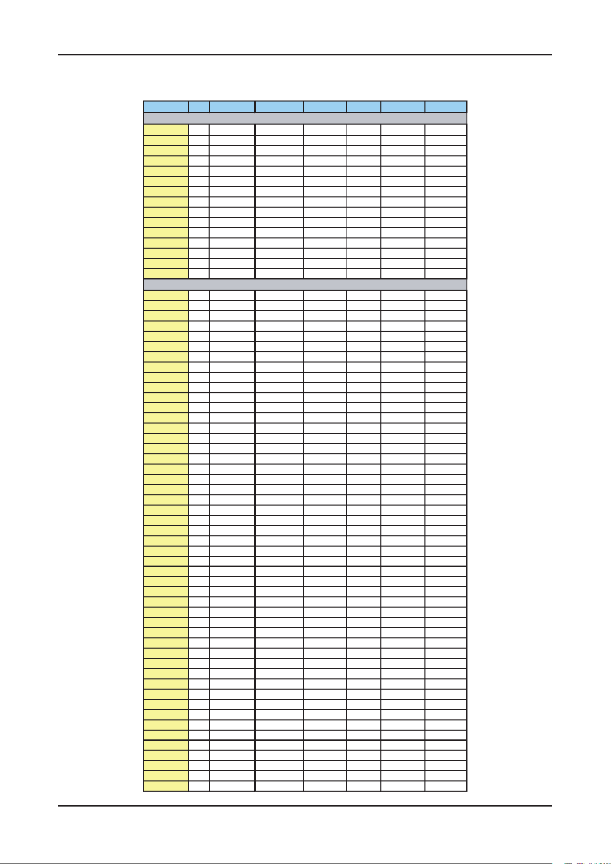
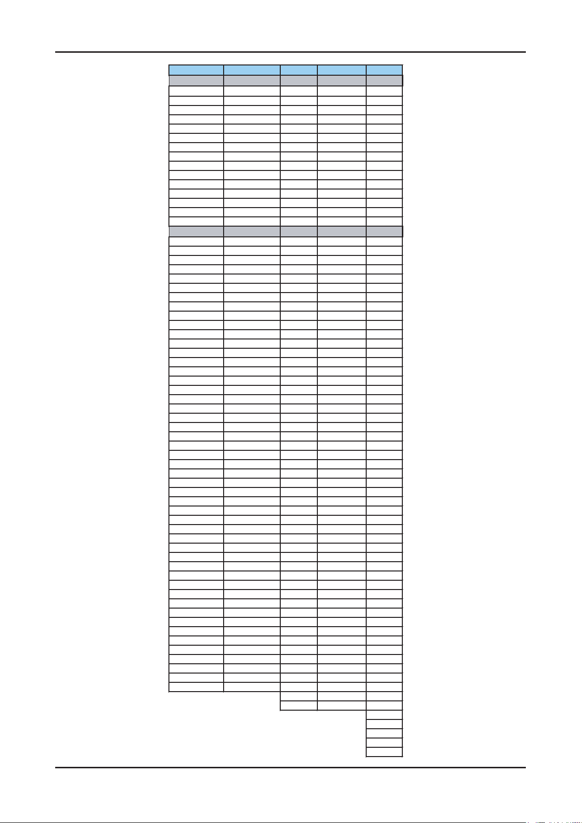
Frequency (DTV)
Channel UK France Germany Italy Spain Sweden Finland
VHF
[A] 56
[B] 64.5
[C] 84.5
[D] 177.5
[5] 178.75 [5] 177.5 [E] 186 [5] 177.5 [5] 177.5
[6] 186.75 [6] 184.5 [F] 194.5 [6] 184.5 [6] 184.5
[7] 194.75 [7] 191.5 [G] 203.5 [7] 191.5 [7] 191.5
[8] 202.75 [8] 198.5 [H] 212.5 [8] 198.5 [8] 198.5
[9] 210.75 [9] 205.5 [H1] 219.5 [9] 205.5 [9] 205.5
[10] 218.75
[10] 212.5 [H2] 226.5 [10] 212.5
[10] 212.5
[11] 219.5 [11] 219.5
[11] 219.5
[12] 226.5 [12] 226.5
[12] 226.5
UHF
21 474 474 474 474 474 474 474
22 482 482 482 482 482 482 482
23 490 490 490 490 490 490 490
24 498 498 498 498 498 498 498
25 506 506 506 506 506 506 506
26 514 514 514 514 514 514 514
27 522 522 522 522 522 522 522
28 530 530 530 530 530 530 530
29 538 538 538 538 538 538 538
30 546 546 546 546 546 546 546
31 554 554 554 554 554 554 554
32 562 562 562 562 562 562 562
33 570 570 570 570 570 570 570
34 578 578 578 578 578 578 578
35 586 586 586 586 586 586 586
36 594 594 594 594 594 594 594
37 602 602 602 602 602 602 602
38 610 6
10 610 610 610 610 610
39 618 618 618 618 618 618 618
40 626 626 626 626 626 626 626
41 634 634 634 634 634 634 634
42 642 642 642 642 642 642 642
43 650 650 650 650 650 650 650
44 658 658 658 658 658 658 658
45 666 666 666 666 666 666 666
46 674 674 674 674 674 674 674
47 682 682 682 682 682 682 682
48 690 690 690 690 690 690 690
49 698 698 698 698 698 698 698
50 706 706 706 706 706 706 706
51 714 714 714 714 714 714 714
52 722 722 722 722 722 722 722
53 730 730 730 730 730 730 730
54 738 738 738 738 738 738 738
55 746 746 746 746 7
46 746 746
56 754 754 754 754 754 754 754
57 762 762 762 762 762 762 762
58 770 770 770 770 770 770 770
59 778 778 778 778 778 778 778
60 786 786 786 786 786 786 786
61 794 794 794 794 794 794 794
62 802 802 802 802 802 802 802
63 810 810 810 810 810 810 810
64 818 818 818 818 818 818 818
65 826 826 826 826 826 826 826
66 834 834 834 834 834 834 834
67 842 842 842 842 842 842 842
68 850 850 850 850 850 850 850
69 858 858 858 858 858 858
Page 13
2-6
2. Product specications
Australia Netherlands China Hongkong Taiwan
[0] 48.5 [1]52. 5
[1] 59.5
[2]60.5
[2] 66.5
[3]68.5
[3] 88.5
[4]80
[4] 97.5 [5] 174.5
[5]88
[5] 104.5 [6] 181.5
[6]171
[5A] 140.5 [7] 188.5
[7]179
[6] 177.5 [8] 195.5
[8]187
[7] 184.5 [9] 202.5
[9]195
[8] 191.5 [10] 209.5
[10]203
[9] 198.5 [11] 216.5
[11]211
[9A] 205.5 [12] 223.5
[12]219
[10] 212.5
[11] 219.5
[12] 226.5
474 [13]474 [21]474 [14]473
482 [14]482 [22]482 [15]479
490 [15]490 [23]490 [16]485
498 [16]498 [24]498 [17]491
506 [17]506 [25]506 [18]497
514 [18]514 [26]514 [19]503
520~526, 6MHz
522 [19]522 [27]522 [20]509
529.5 530 [20]530 [28]530 [21]515
536.5 538 [21]538 [29]538 [22]521
543.5 546 [22]546 [30]546 [23]527
550.5 554 [23]554 [31]554 [24]533
557.5 562 [24]562 [32]562 [25]539
564.5 570 [25]610 [33]570 [26]545
571.5 578 [26]618 [34]578 [27]551
578.5 586 [27]626 [35]586 [28]557
585.5 594 [28]634 [36]594 [29]563
592.5 602 [29]642 [37]602 [30]569
599.5 610 [30]650 [38]610 [31]575
606.5 618 [31]658 [39]618 [32]581
613.5 626 [32]666 [40]626 [33]58
7
620.5 634 [33]674 [41]634 [34]593
627.5 642 [34]682 [42]642 [35]599
634.5 650 [35]690 [43]650 [36]605
641.5 658 [36]698 [44]658 [37]611
648.5 666 [37]706 [45]666 [38]617
655.5 674 [38]714 [46]674 [39]623
662.5 682 [39]722 [47]682 [40]629
669.5 690 [40]730 [48]690 [41]635
676.5 698 [41]738 [49]698 [42]641
683.5 706 [42]746 [50]706 [43]647
690.5 714 [43]754 [51]714 [44]653
697.5 722 [44]762 [52]722 [45]659
704.5 730 [45]770 [53]730 [46]665
711.5 738 [46]778 [54]738
[47]671
718.5 746 [47]786 [55]746 [48]677
725.5 754 [48]794 [56]754 [49]683
732.5 762 [49]802 [57]762 [50]689
739.5 770 [50]810 [58]770 [51]695
746.5 778 [51]818 [59]778 [52]701
753.5 786 [52]826 [60]786 [53]707
760.5 794 [53]834 [61]794 [54]713
767.5 802 [54]842 [62]802 [55]719
774.5 810 [55]850 [63]810 [56]725
781.5 818 [56]858 [64]818 [57]731
788.5 826 [57]866 [65]826 [58]737
795.5 834 [58]874 [66]834 [59]743
802.5 842 [59]882 [67]842 [60]749
809.5 850 [60]890 [
68]850 [61]755
816.5 858 [61]898 [69]858 [62]761
[62]906 [63]767
[63]914 [64]773
[65]779
[66]785
[67]791
[68]797
[69]803
Page 14
2-7
2. Product specications
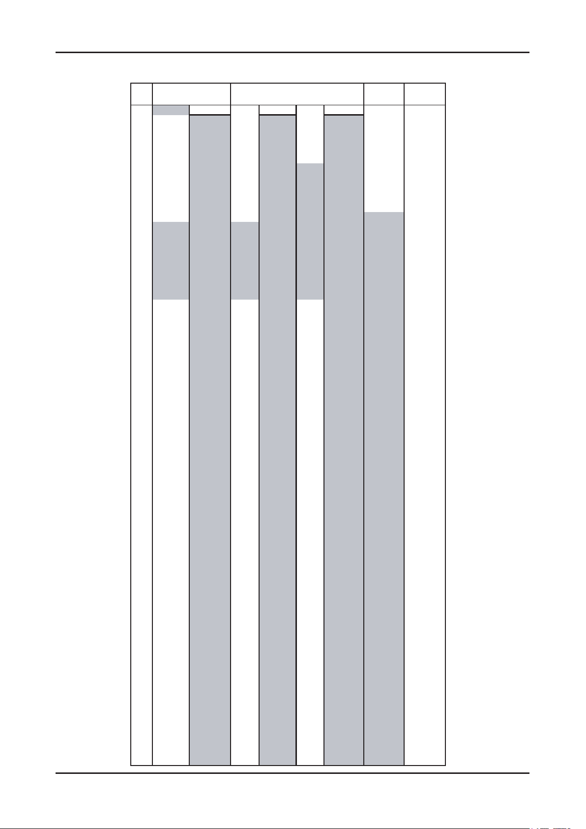
CH
NEWZEAL CHINA
(PAL D/K)
1 69-855.25 49.25
69-855.25
176.00 69-855.25 45.25 49.25
2 48.25 E2-48.25 59.25 184.00 FA-47.75 55.25 57.25
3 55.25 E3-55.25 77.25 192.00 FB-55.75 62.25 65.25
4 62.25 E4-62.25 85.25 200.00
FC1-60.50
175.25 77.25
5 175.25 X -69.25 93.25 208.00 FC-53.75 182.25 85.25
6 182.25 Y -76.25 175.25 216.00 B-116.75 189.25 168.25
7 189.25 Z -83.25 183.25 C-128.25 196.25 176.25
8 196.25 Z1-90.25 191.25 D-140.75 203.25 184.25
9 203.25 Z2-97.25 199.25 E-152.75 210.25 192.25
10 210.25 S1-105.25 207.25 F-164.75 217.25 200.25
11 217.25 S2-112.25 215.25 F1-176.00 224.25 208.25
12 224.25 S3-119.25 223.25 G -176.75 216.25
13 S4-126.25 F2-184.00 471.25
14 S5-133.25 H -188.75 479
.25
15 S6-140.25 F3-192.00 487.25
16 S7-147.25 F4-200.00 495.25
17 S8-154.25 I -200.75 503.25
18 S9-161.25 F5-208.00 511.25
19 S10-168.25 J -212.75 519.25
20 E5-175.25 F6-216.00 527.25
21 471.25 E6-182.25 471.25 471.25 K -224.75 535.25
22 479.25 E7-189.25 479.25 479.25 L -236.75 543.25
23 487.25 E8-196.25 487.25 487.25 M -248.75 551.25
24 495.25 E9-203.25 495.25 495.25 N -260.75 559.25
25 503.25
E10-210.25
503.25 503.25 O -272.75 607.25
26 511.25
E11-217.25
511.25 511.25 P -284.75 615.25
27 519.25
E12-224.25
519.25 519.25 Q -296.75 623.25
28 527.25
S11-231.25
527.25 527.25 631.25
29 535.25
S12-238.25
535.25 535.25 639.25
30 543.25
S13-245.25
543.25 543.25 647.25
31 551.25
S14-252.25
551.25 551.25 655.25
32 559.25
S15-259.25
559.25 559.25 663.25
33 567.25
S16-266.25
567.25 567.25 671.25
34 575.25
S17-273.25
575.25 575.25 679.25
35 583.25
S18-280.25
583.25 583.25 687.25
36 591.25
S19-287.25
591.25 591.25 695.25
37 599.25
S20-294.25
599.25 599.25 703.25
38 607.25
S21-303.25
607.25 607.25 711.25
39 615.25
S22-311.25
615.25 615.25 719.25
40 623.25
S23-319.25
623.25 623.25 727.25
41 631.25
S24-327.25
631.25 631.25 735.25
42 639.25
S25-335.25
639.25 639.25 743.25
43 647.25
S26-343.25
647.25 647.25 751.25
44 655.25
S27-351.25
655.25 655.25 759.25
45 663.25
S28-359.25
663.25 663.25 767.25
46 671.25
S29-367.25
671.25 671.25 775.25
47 679.25
S30-375.25
679.25 679.25 783.25
48 687.25
S31-383.25
687.25 687.25 791.25
49 695.25
S32-391.25
695.25 695.25 799.25
50 703.25
S33-399.25
703.25 703.25 807.25
51 711.25
S34-407.25
711.25 711.25 815.25
52 719.25
S35-415.25
719.25 719.25 823.25
53 727.25
S36-423.25
727.25 727.25 831.25
54 735.25
S37-431.25
735.25 735.25 839.25
55 743.25
S38-439.25
743.25 743.25 847.25
56 751.25
S39-447.25
751.25 751.25 855.25
57 759.25
S40-455.25
759.25 759.25 863.25
58 767.25
S41-463.25
767.25 767.25 871.25
59 775.25 775.25 775.25 879.25
60 783.25 783.25 783.25 887.25
61 791.25 791.25 791.25 895.25
62 799.25 799.25 799.25 903.25
63 807.25 807.25 807.25 911.25
64 815.25 815.25 815.25 919.25
65 823.25 823.25 823.25 927.25
66 831.25 831.25 831.25 935.25
67 839.25 839.25 839.25 943.25
68 847.25 847.25 847.25 951.25
FRANCE
(SECAM-L)
CCIR
(PAL B/G)
OIRT
(SECAM D/K)
Frequency (ATV)
Page 15
2. Product specications
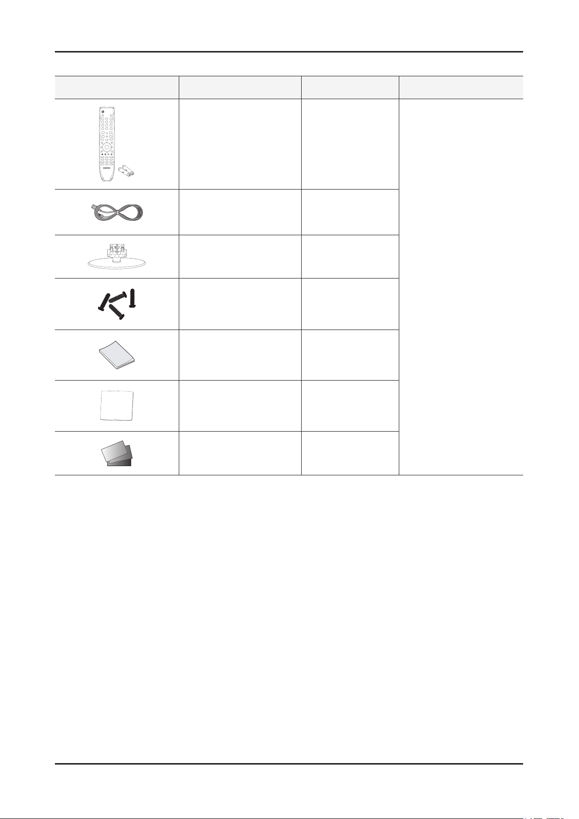
2-4. Accessories
Product Description Code. No Remark
Remote Control & Batteries
(AAA x 2)
Power Cord 3903-000456
Stand
Screws
(for the stand - M4)
Owner’s Instructions BN68-02588A
Cleaning Cloth BN63-01798B
BN59-01005A
19" : BN96-12868B
22" : BN96-12887B
6002-001294
Samsung Electronics
Service center
Warranty Card / Registration
Card / Safety Guide Manual
(Not available in all locations)
-
2-8
Page 16
3. Disassembly and Reassembly
3. Disassembly and Reassembly
This section of the service manual describes the disassembly and reassembly procedures for the LE19/22C450 LCD TV.
WARNING: This LCD TV contains electrostatically sensitive devices. Use caution when handling these components.
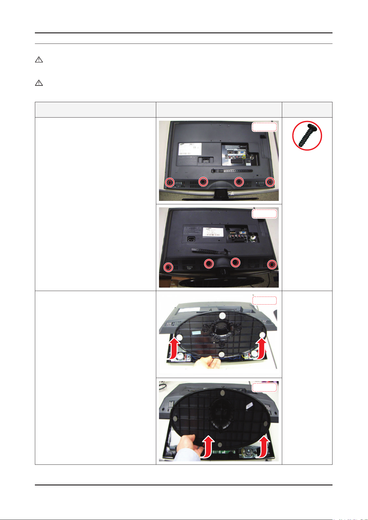
3-1. Disassembly and Reassembly
Cautions: 1. Disconnect the LCD TV from the power source before disassembly.
2. Follow these directions carefully; never use metal instruments to pry apart the cabinet.
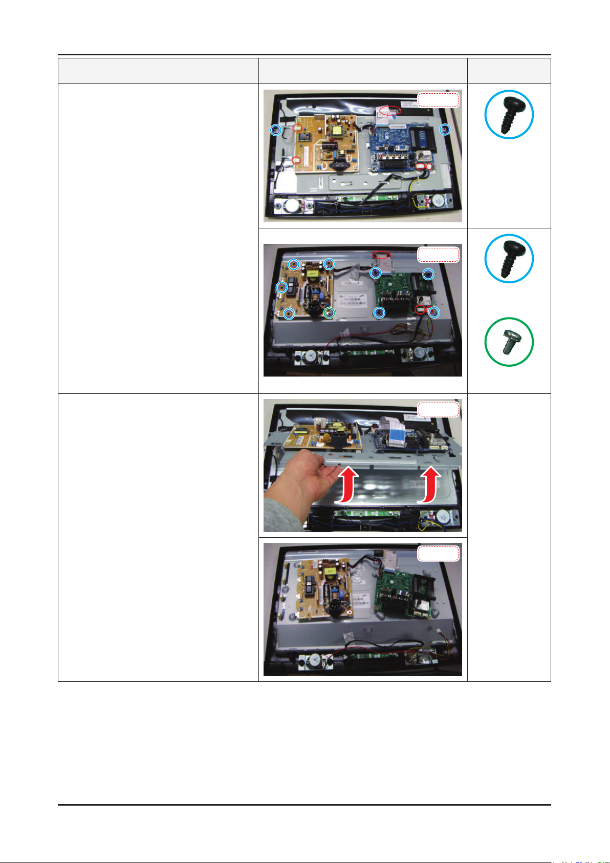
Description Picture Description Screws
1. Place the TV face down on cushioned table.
Remove screws from the stand and back.
19 inch : 4 screws
22 inch : 4 screws
2. Lift up the rear cover.
19 inch
6002-001294
(M4 x L16, Tapping)
22 inch
19 inch
22 inch
3-1
Page 17
3-2
3. Disassembly and Reassembly
Description Picture Description Screws
3. Remove screws and disconnect conectors.
19 inch : 2 screws
22 inch : 10 screws
19 inch
6003-000269
(M3 x L6, TAPTYPE)
22 inch
6003-000269
(M3 x L6, TAPTYPE)
6003-001439
(M4 x L8, TAPTYPE
4. Lift up the bracket and remove it.
19 inch
22 inch
Page 18
3-3
3. Disassembly and Reassembly
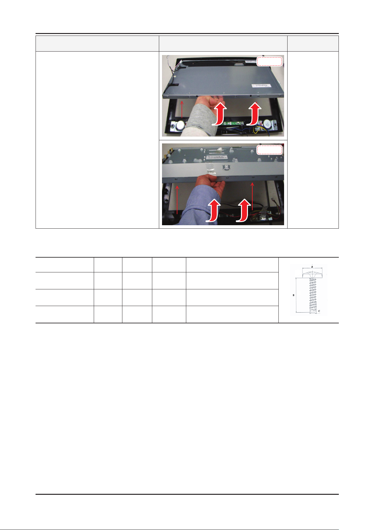
Description Picture Description Screws
5. Lift up the panel.
Reassembly procedures are in the reverse order of disassembly procedures. ※
19 inch
22 inch
Screw Size
Code No. A (mm) B (mm) C (mm) Q’ty
6002-001294 8.3±0.5 16±0.8 3.85~4.0 -
6003-000275 5.80~6.30 9.2~10.0 2.85~2.95 -
6003-001439 8.3±0.4 8.0±0.4 3.85~3.93 1(ALL)
Page 19

4. Troubleshooting
4-1. Troubleshooting
4-1-1. Previous check
Check the various cable connections rst. 1.
• Check to see if there is a burnt or damaged cable.
• Check to see if there is a disconnected or loose cable connection.
• Check to see if the cables are connected according to the connection diagram.
Check the power input to the Main Board.2.
4. Troubleshooting
4-1
Page 20
4-2
4. Troubleshooting
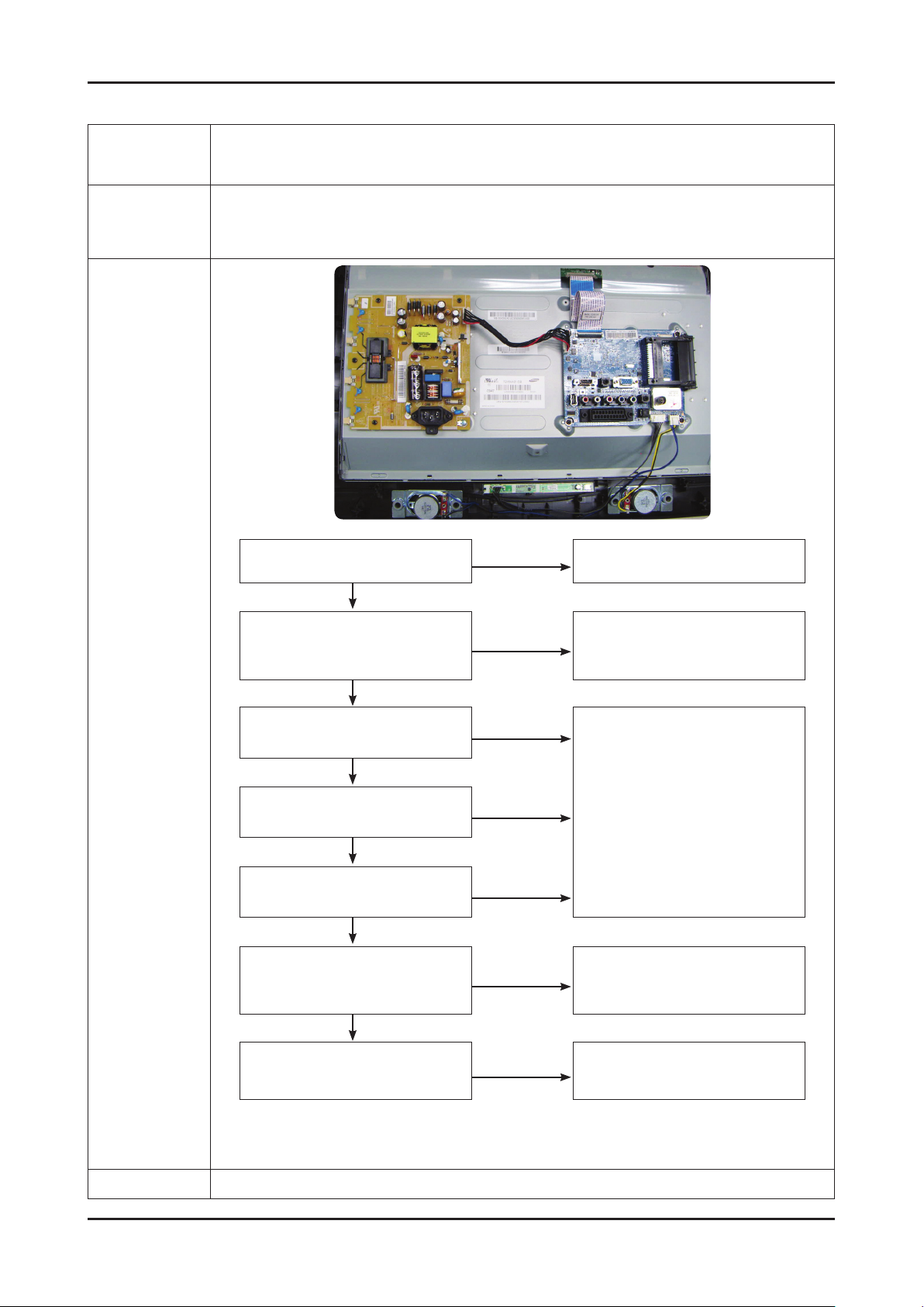
4-1-2. No Power
Symptom
The IP relay or the LEDs on the front panel does not work when connecting the power cord if the cables are
Major
checkpoints
improperly connected or the Main Board or SMPS is not functioning. In this case, check the following:
The LEDs on the front panel do not work when connecting the power cord. The SMPS relay does not work when connecting the power cord. The units appears to be dead. -
Check the internal cable connection status inside the unit. Check the fuses of each part. - Check the output voltage of SMPS. - Replace the Main Board. -
Diagnostics
Lamp(Backlight) Off,
power indicator LED on?
Yes
Does proper Stand-by
DC A5V_PW(A5V_1) and
A13V_PW(A13V1) appear?
Yes
Does proper Main B13V_PW(B13V1),
B5V_PW(B5V1) appear?
Yes
Does proper DC A3.3V(A3.3V1)
appear?
Yes
Does proper B3.3V_PW(B3.3V1),
B1.8V_PW(B1.8V1) appear?
Yes
Does proper PANEL_5V
appear at LVDS connector
Pin#1~5 of T-con B’D?
Yes
No
No
No
No
No
No
Change the power cable or IP board.
Change the IP Board.
Change the Main Board.
Change the LVDS cable.
Caution
A power is supplied to set?
Make sure to disconnect the power before working on the IP board.
No
Check a other function.
(No picture part)
Replace a LCD Panel.
Page 21

4-3
4. Troubleshooting
LE26/32B45***
Power CN2001
Pin 1 2 3 4 5 6 7 8 9
Dimming out A13V GND GND GND A5V A5V NC Panel Setting
Page 22

4-4
4. Troubleshooting
4-1-3. No Video (Analog PC signal)
Symptom Audio is normal but no picture is displayed on the screen. -
Major
checkpoints
Check the PC source -
Check the Arsenal, Check the Chelsea. This may happen when the LVDS cable connecting the Main Board and the Panel is disconnected. -
Power indicator LED is off.
Lamp(Backlight) on, no video
Yes
Check the PC source and
check the connection of D-SUB
Yes
No
No
Check a set
in the ‘Stand-by mode’ or
‘DPMS mode’
Input the analog
PC signal properly.
Diagnostics
Does the signal appear at
1
TP - PC_R, PC_G, PC_B, PC_HS,
PC_VS (R, G, B, H, V)?
Yes
2
Does the digital data appear at
ODD_TXCLK+(D3+),
ODD_TXCLK-(D3-)?
Yes
Check the LVDS cable?
Check the T-Con B’d?
Replace the LCD panel?
No
No
No
Check CN902, PC cable.
Change the Main Assy.
Check IC1102(SETD-10).
Change the main Assy.
Please, Contact Tech support.
Caution Make sure to disconnect the power before working on the IP board.
Page 23

4-5
4. Troubleshooting
Page 24

4-6
4. Troubleshooting
WAVEFORMS
1
2
PC input (V-sink , H-sink , R/G/B)
LVDS output
Page 25

4-7
4. Troubleshooting
4-1-4. No Video (HDMI - Digital Signal)
Symptom Audio is normal but no picture is displayed on the screen. -
Major
checkpoints
Check the HDMI source. -
Check the HDMI switch, Check the Chelsea. -
This may happen when the LVDS cable connecting the Main Board and the Panel is disconnected. -
Power Indicator is off.
Lamp(Backlight) Off, no video?
Yes
Check the HDMI source and check
the connection of HDMI cable?
Yes
No
No
Check a set
in the ‘Stand-by mode’.
Input the HDMI signal properly
Diagnostics
3
2
Does the signal appear at
CN1001 (Pin #12(RX_CLK),
#7(RX_DATA)) ?
Yes
Does the digital data appear at
ODD_TXCLK+(D3+),
ODD_TXCLK-(D3-)?
Yes
Check the LVDS cable?
Check the T-Con B’d?
Replace the LCD panel?
No
No
No
Check CN1001 and HDMI Cable.
Change the Main Assy.
Check IC1102(SETD-10).
Change the main Assy.
Please, Contact Tech support
Caution Make sure to disconnect the power before working on the IP board.
Page 26

4-8
4. Troubleshooting
Page 27

4-9
4. Troubleshooting
WAVEFORMS
3
2
HDMI input (RX_Data, RX_Clk)
LVDS output
Page 28

4-10
4. Troubleshooting
4-1-5. No Video (Tuner_CVBS)
Symptom Audio is normal but no picture is displayed on the screen. -
Major
checkpoints
Check the Tuner CVBS source. -
Check the Tuner, Check the Chelsea. -
This may happen when the LVDS cable connecting the Main Board and the Panel is disconnected. -
Is power inductor LED off?
Lamp(Backlight) on and no video?
Yes
Check the RF source
and the connection.
Yes
No
No
Check a set
in the ‘Stand-by mode’.
Input the RF source properly.
Diagnostics
4
Does the CVBS data appear at R836?
Yes
Does the DC B5V_PW, TU33V_PW
appear at pin #3, 5 of tuner?
Yes
Does the digital data appear at
2
ODD_TXCLK+(D3+),
ODD_TXCLK-(D3-)?
Yes
Check the LVDS cable?
Check the T-Con B’d?
Replace the LCD panel?
No
No
No
No
Change the Main Assy
Check Tuner
Change the Main Assy
Check IC1102(SETD-10).
Change the main Assy.
Please, Contact Tech support
Caution Make sure to disconnect the power before working on the IP board.
Page 29

4-11
4. Troubleshooting
Page 30

4-12
4. Troubleshooting
WAVEFORMS
CVBS OUT (Grey Bar)
4
LVDS output
2
Page 31

4-13
4. Troubleshooting
4-1-6. No Video (Tuner DTV)
Symptom Audio is normal but no picture is displayed on the screen. -
Major
checkpoints
Check the DTV source. -
Check the Tuner, Check the Chelsea. -
This may happen when the LVDS cable connecting the Main Board and the Panel is disconnected. -
Power indicator LED is off.
Lamp(Backlight) on, no video
Yes
Check the connection of RF cable
No
No
Check a set
in the ‘Stand-by mode’.
Input the RF cable properly.
Diagnostics
Yes
Check the ‘signal strength’
in Self Diagnosis menu
Strength is enough?
Yes
Does the DC B5V_TU_PW, TU33V_PW
appear at pin #3, #5 of tuner?
Yes
2
Does the digital data appear at
ODD_TXCLK+(D3+),
ODD_TXCLK-(D3-)?
Yes
Check the LVDS cable?
Check the T-Con B’d?
Replace the LCD panel?
No
No
No
No
Check the D-TV source.
Change the Main Assy
Check IC1102(SETD-10).
Change the main Assy.
Please, Contact Tech support
Caution Make sure to disconnect the power before working on the IP board.
Page 32

4-14
4. Troubleshooting
Page 33

4-15
4. Troubleshooting
WAVEFORMS
2
LVDS output
Page 34

4-16
4. Troubleshooting
4-1-7. No Video (Video CVBS)
Symptom Audio is normal but no picture is displayed on the screen. -
Major
checkpoints
Check the Video CVBS source -
Check the Chelsea. -
This may happen when the LVDS cable connecting the Main Board and the Panel is disconnected. -
Power indicator LED is off.
Lamp(Backlight) on, no video?
Yes
Check the video source and
check the connection of video cable?
Yes
No
No
Check a set
in the ‘Stand-by mode’.
Input the video source properly.
Diagnostics
4
2
Does the CVBS data appear at
TP-AV_CVBS?
Yes
Does the digital data appear at
ODD_TXCLK+(D3+),
ODD_TXCLK-(D3-)?
Yes
Check the LVDS cable?
Check the T-Con B’d?
Replace the LCD panel?
No
No
No
Check CN801.
Change the main assy.
Check IC1101(SETD-10).
Change the main assy.
Please, Contact Tech support
Caution Make sure to disconnect the power before working on the IP board.
Page 35

4-17
4. Troubleshooting
Page 36

4-18
4. Troubleshooting
WAVEFORMS
CVBS OUT (Grey Bar)
4
LVDS output
2
Page 37

4-19
4. Troubleshooting
4-1-8. No Video (Component)
Symptom Audio is normal but no picture is displayed on the screen. -
Major
checkpoints
Check the Component source -
Check the chelsea. -
This may happen when the LVDS cable connecting the Main Board and the Panel is disconnected. -
Power indicator LED is off.
Lamp(Backlight) on, no video?
Yes
Check the component source and
check the connection of
component cables(Y,Pb,Pr)?
No
No
Check a set
in the ‘Stand-by mode’.
Input the component
source properly.
Diagnostics
Yes
Does the component daga appear at
5
TP-COMP_Y, COMP_PB, COMP_PR?
Yes
Does the digital data appear at
2
ODD_TXCLK+(D3+),
ODD_TXCLK-(D3-)?
Yes
Check the LVDS cable?
Check the T-Con B’d?
Replace the LCD panel?
No
No
No
Check CN802.
Change the main assy.
Check IC1102(SETD-10).
Change the main assy.
Please, Contact Tech support
Caution Make sure to disconnect the power before working on the IP board.
Page 38

4-20
4. Troubleshooting
Page 39

4-21
4. Troubleshooting
WAVEFORMS
5
2
Compnent_Y (Gray scale) / Pb / Pr (Color bar)
LVDS output
Page 40

4-22
4. Troubleshooting
4-1-9. No Sound
Symptom Video is normal but there is no sound.. -
Major
checkpoints
When the speaker connectors are disconnected or damaged. -
When the sound processing part of the Main Board is not functioning. -
Speaker defect.. -
Check the source and
check the connection of sound cable
(Comp/PC/DVI to HDMI).
Yes
No
Input the sound source properly.
Diagnostics
Does the sound data appear at
TP-COMP_SL_IN, COMP_SR_IN(COMP/AV)?
TP-PC_SL_IN, PC_SR_IN(PC/DVI)?
TP-SC_SL_IN, TP_SR_IN(SCART)?
Yes
Does the B13V(B13V1) appear?
Yes
6
Does thd I2S data appear at R1390?
Yes
Does the sound data appear
7
TP-SPK_L-, SPK_L+,
SPK_R-, SPK_R+?
Yes
Replace speaker.
No
No
No
No
No
Check CN802, CN901, JA701_EU.
Change the main assy.
Change the Main Assy
CHECK IC1102(SETD-10).
Change the main assy.
Check IC1301(Sound AMP)
Change the main assy.
Please, Contact Tech support.
Caution Make sure to disconnect the power before working on the IP board.
Page 41

4-23
4. Troubleshooting
Page 42

4-24
4. Troubleshooting
WAVEFORMS
I2S DATA
6
Speaker out
7
Page 43

4-25
4. Troubleshooting
4-2. Alignments and Adjustments
4-2-1. General Alignment Instuction
Usually, a color LCD-TV needs only slight touch-up adjustment upon installation. 1.
Check the basic characteristics such as height, horizontal and vertical sync.
Use the specied test equipment or its equivalent.2.
Correct impedance matching is essential.3.
Avoid overload. Excessive signal from a sweep generator might overload the front-end 4.
of the TV. When inserting signal markers, do not allow the marker generator to distort test result.
Connect the TV only to an AC power source with voltage and frequency as specied on 5.
the backcover nameplate.
Do not attempt to connect or disconnect any wire while the TV is turned on. Make sure 6.
that the power cord is disconnected before replacing any parts.
To protect against shock hazard, use an isolation transformer.7.
Page 44

4-26
4. Troubleshooting
4-3. Factory Mode Adjustments
4-3-1 Entering Factory Mode
To enter ‘Service Mode’ Press the remote -control keys in this sequence :
- If you do not have Factory remote - control
Power OFF MENU MUTE
INFO
4-3-2 How to Access Service Mode
Using the Customer Remote
Turn the power off and set to stand-by mode.1.
Press the remote buttons in this order; POWER OFF- INFO - MENU - MUTE to turn the set on.2.
The set turns on and enters service mode. This may take approximately 20 seconds.3.
Press the Power button to exit and store data in memory. 4.
- If you fail to enter service mode, repeat steps 1 and 2 above.
Initial SERVICE MODE DISPLAY State 5.
Option
Control
SVC
Expert
ADC/WB
Advanced
T-TDT5DEUC-XXXX
T-TDT5DEUS-XXXX
EDID SUCCESS
CALIB : AV X COMP X PC X HDMI X
Option : XXXX XXXX XXXX X
T-TDTDEU-XXX
SDAL-XXX
RFS : P0155 T-TDT5DEUC
20XX-XX-XX
TYPE : XX
MODEL : XXXXX
MAC Not Available
FACTORY DATA VER : XXX
EERC VERSION : XXX
DTP-AP-COMP-XXX-XX
DTP-HIIG-XXXX-X
DTP-BP-XXXX
DATE OF PURCHASE : XX/XX/XX
* How to enter the hidden factory mode.
a. into the factory mode
b. move the tap to Advanced
c. key input : 0 + 0 + 0 + 0
** hidden menu : Advanced
6. Buttons operations withn Service Mode
Menu Full Menu Display/Move to Parent Menu
Direction Keys
Direction Keys
Source
Item Selection by Moving the Cursor
/
Data Increase / Decrease for the Selected Item
/
Cycles through the active input source that are connected to the unit
Page 45

4-27
4. Troubleshooting
4-3-3 Factory Data
Option
OPTION
Factory
Name
Factory Reset
Type
Local Set EU EU/EU_Italy/EU_Africa/EU_Israel/NORDIG/AD_Au/CIS Select Area
Model LC350
TUNER DRXKSEMCO
DDR 0 0/1/2
Data Range Use
NONE/19O6TH0C/19A6TH0C/22I6TH0C/22A6TH0C/22
D6TH0C/22P6TH0C/26A6AH0C/26D6AH0C/26L6AH0C
/26P6AH0C/32A6AH0C32D6AH0C/32L6AH0C32P6AH0
C/32A6AF0C/32L6AF0C/32A1AF0C/32L1AF0C/37L6AF
0C/37L1AF0C/40A6AF0C/40D6AF0C/40L6AF0C/40A1A
F0C/40L1AF0C/40A1UF0C/40D1UF0C/40L1UF0C/46A6
AF0C/46D6AF0C/46L6AF0C/46A1AF0C/46L1AF0C/46A
1UF0C/46D1UF0C/46L1UF0C/55A1UF0C/55L1UF0C/6
5L1UF0C/19R6TH0E/22D6TH0E/26D6AH0E/32D6AH0
E32D6UF0E/32A1UF0E/32D1UF0E/37L6UF0E/37D1UF
0E/37L1UF0E/40D6UF0E/40A1UF0E/40D1UF0E/46D6
UF0E/46L6UF0E/46A1UF0E/46D1UF0E/46L1UF0E/55A
1UF0E/55D1UF0E/55L1UF0E/65L1UF0E/42HHcD3/50H
HcD450FArN4/50FArV458FArN1/58FArV163FArN1/
LC350/LC450/LC450H/LC451/LC452/LC457HLC459H/
LC480/LC530/LC530H/LC539H/LC540/LC550/LC560/
LC580/LC570/LC610/LC620/LC630/LC631/LC632/
LC633/LC640/LC650/LC652/LC653/LC654/LC670/
UC400/UC400H/UC4010/UC5000/UC5100/UC6000/
UC6200/UC6300/UC6400/UC6400H/UC6500/UC6510/
UC6530/UC6540/UC6550/UC6600/UC6620/UC6630/
UC6700/UC6720/UC6730/UC6740/UC6800/UC6830/
UC6900/UC6900H/UC8000/
PC420/PC430/PC431/PC432/PC450/PC451/PC480/
PC520/PC530/PC531/PC540/PC541/PC550/PC551/
PC560/PC580/PC590/PC670/PC6100/PC6400/PC6500/
PC7000/PC7700/PC8000
DRXKSEMCO/S2Semco/T2CXD/DRXKSEM_E/
DRXKALPS/DRXKSEN_2/DRXKXG
Select Panel
Type
12 : inch
3 : vendor
4 : refresh
5 : POL
6 : resolution
7 : multi
8 : BLU
Select Model
EU :
DRXKSEMCO
AU :
DRXKALPS
satellite :
S2Semco
Light Effect OFF OFF/ON
NONE/PBA/SUWON/SESK/SHE/SERK
Ch Table
Country … - -
Front Color
/SDMA_AU/SDMA_NZ/SDMA/SG/SEIN/SAVINA
/SIEL_C/SIEL_N/TTSEC/TSED/TSE/IRAN/SESK_T2/
NONE/W-MILKY/T-M-Brn/T-W-Brn/T-W-Gray/W-D-
Gray/W-M-Whit/W-Violet/T-C-Gray/T-R-BLK/S-BLK/S-
RBLK/S-C-Gray/
Select Design
for Illuminance
Sensor
Page 46

4-28
4. Troubleshooting
Control
Control
EDID
Factory Name Data Range
EDID
Sub Option
Shop Option
Sound
Factory Name Data Use
EDID ON/OFF OFF
EDID WRITE ALL …
EDID WRITE PC …
EDID WRITE
HDMI
EDID WRITE
HDMI1
EDID WRITE
HDMI2
EDID WRITE
HDMI3
EDID WRITE
HDMI4
EDID 1.2 PORT …
…
…
…
…
…
Download EDID data to EEPROM.
1. Set "ON" of EDID ON/OFF.
2. Go EDID WRITE ALL and Push Enter or ► button.
3. If You See Success message, SET "OFF" of EDID ON/OFF.
Sub Option
EDID WRITE DVI …
Factory Name Data RANGE Use
RS-232 Jack UART Debug/Logic/UART
Watchdog ON ON/OFF
WD Count 0 255
Dimm Type EXT xed
Lvds Format JEIDA JEIDA/VESA/19INCH
OTN Server Type operating operating/development
OTN Test Server OFF OFF/ A/B/C/D/E Zone
OTN Support ON ON/OFF
OTN Reset not modifyed
OTN Duration OFF ON/OFF
OTN Fail Test OFF ON/OFF
T-CON USB
Download
View Log not modifyed
Failure xed
Select Setting of UART port.
Initial value is "UART"
Select Watchdog.
Initial value is "ON"
Watchdog Count.
Read Only.
Select Dimming Type.
Initial value is "EXT"
Select LVDS format.
19inch : VESA"
other inch : "JEIDA"
Page 47

4-29
4. Troubleshooting
Hotel Option
Shop Option
Sound
Factory Name Data Range
Hotel Mode OFF
SI Vender …
Power On
Channel
Channel Type …
Power On Volume …
Min Volume …
Max Volume …
Panel Button Lock …
Power On Source …
Factory Name Data Range
Shop Mode OFF ON/OFF
Exhibition Mode OFF ON/OFF
Factory Name Data Range Use
High Devi OFF ON/OFF
…
Carrier_Mute ON ON/OFF
Speaker Delay
Normal
Pilot Level High Thld 0x70h 0x00~0xff Control for ATV sound of stereo / multiplex
Pilot Level Low Thld 0x20h 0x00~0xff Control for ATV sound of stereo / multiplex
Speaker EQ ON ON/OFF Control for sound precision
10 0~255 Audio delay for Lipsync
Page 48

4-30
4. Troubleshooting
SVC
SVC
Test Pattern
TUNER STATUS
Factory Name Data Range
Test Pattern
Panel Auto Setting
Panel Display
Time
Logic Usb D/L off
Tuner Status
Factory Name Data Range Use
Pattern Sel OFF
FRC PC Mode … ON/OFF
Logic Pattern Sel … Not modied
Logic Level Sel … Not modied
Factory Name Factory Name Range
0Hr
OFF/ White/Grey/Black
Red/Green/Blue
SNR Not modied
BER Not modied
xed
Test for Input of Scaler.
If you can see pattern well, there is
problem at input of Scaler.
DVB
Singal Strength Not modied
Bandwidth Not modied
Frequency Not modied
LNA Status Not modied
FFT Not modied
Modulation Not modied
Code Rate Not modied
GI Not modied
Hier Modulation Not modied
Frequency Offset Not modied
Timing Offset Not modied
AGC Not modied
UCB Not modied
PLL Type Not modied
DEMOD Type Not modied
TPS LOCK Not modied
RS Lock Not modied
SSI Not modied
SQI Not modied
Page 49

4-31
4. Troubleshooting
ISDB-T
FFT Size_1 Not modied
Guard Interval_1 Not modied
Freq. Offset_1 Not modied
SNR_1 Not modied
IF AGC_1 Not modied
TMCC Lock_1 Not modied
TS Packet_1 Not modied
Master Lock_1 Not modied
A_Modulation_1 Not modied
A_Code Rate_1 Not modied
A_Timer
InterLeave_1
A_Segments
Num_1
A_Ber_1 Not modied
B_Modulation_! Not modied
B_Code Rate_1 Not modied
B_Timer
InterLeave_1
B_Segments
Num_1
B_BER_1 Not modied
Not modied
Not modied
Not modied
Not modied
SVC
C_Modulation_1 Not modied
C_Code Rate_1 Not modied
C_Timer
InterLeave_1
C_Segments
Num_1
C_BER_1 Not modied
Not modied
Not modied
Expert
Factory Name Data Range
N / D ADJ Off Off / On / FIX
SOURCE ... Not modied
Page 50

4-32
4. Troubleshooting
ADC/WB
ADC/WB
ADC
ADC Target
Factory Name Data Range
ADC
ADC Target
ADC RESULT
WB
Factory Name Data Range
AV Calibration Success Success / Failure
Comp Calibration Success Success / Failure
PC Calibration Success Success / Failure
HDMI Calibration Success Success / Failure
Factory Name Data Range
1st_AV_Low 64 0 ~ 1023
1st_AV_High 880 0 ~ 1023
1st_AV_Delta 2 0 ~ 7
1st_COMP_Y_Low 64 0 ~ 1023
1st_COMP_Y_High 940 0 ~ 1023
1st_COMP_Delta 2 0 ~ 7
1st_PC_R_Low 16 0 ~ 1023
1st_PC_R_High 1004 0 ~ 1023
1st_PC_Delta 2 0 ~ 7
2nd_AV_R_Low 4 -
2nd_AV_G_Low 4 0 ~ 1023
2nd_AV_B_Low 4 -
2nd_AV_R_High 940 -
2nd_AV_G_High 940 0 ~ 1023
2nd_AV_B_High 940 -
2nd_AV_Delta 2 0 ~ 7
2nd_COMP_R_Low 4 -
2nd_COMP_G_Low 4 0 ~ 1023
2nd_COMP_B_Low 4 -
2nd_COMP_R_High 940 -
2nd_COMP_G_High 940 0 ~ 1023
2nd_COMP_B_High 940 -
2nd_COMP_Delta 2 0 ~ 7
2nd_PC_R_Low 4 -
2nd_PC_G_Low 4 0 ~ 1023
2nd_PC_B_Low 4 -
Page 51

4-33
4. Troubleshooting
2nd_PC_R_High 940 -
2nd_PC_G_High 940 0 ~ 1023
2nd_PC_B_High 940 -
2nd_PC_Delta 2 0 ~ 7
2nd_HDMI_R_Low 4 -
2nd_HDMI_G_Low 4 0 ~ 1023
2nd_HDMI_B_Low 4 -
2nd_HDMI_R_High 940 -
2nd_HDMI_G_High 940 0 ~ 1023
2nd_HDMI_B_High 940 -
2nd_HDMI_Delta 2 0 ~ 7
ADC RESULT
WB
Factory Name Data Range
1st_Y_GH 0 0 ~ 255
1st_Y_GL 0 0 ~ 255
1st_Cb_BH 0 0 ~ 255
1st_Cb_BL 0 0 ~ 255
1st_Cr_RH 0 0 ~ 255
1st_Cr_RL 0 0 ~ 255
2nd_R_L 132 0 ~ 255
2nd_G_L 132 0 ~ 255
2nd_B_L 132 0 ~ 255
2nd_R_H 50 0 ~ 255
2nd_G_H 50 0 ~ 255
2nd_B_H 50 0 ~ 255
Factory Name Data Range
Sub Brightness 128 0 ~ 255
R_Offset 512 0 ~ 1023
G_Offset 512 0 ~ 1023
B_Offset 512 0 ~ 1023
Sub Contrast 128 0 ~ 255
R_Gain 512 0 ~ 1023
G_Gain 512 0 ~ 1023
B_Gain 512 0 ~ 1023
Movie R Offset - 0 ~ 1023
Movie B Offset - 0 ~ 1023
Movie R Gain - 0 ~ 1023
Movie B Gain - 0 ~ 1023
Page 52

4-34
4. Troubleshooting
4-4. White Balance - Calibration
4-4-1 White Balance -Calibration
1. Calibration
AV Calibration
Comp Calibration
PC Calibration
HDMI Calibration
4-4-2 White Balance - Adjustment
(low light) (hight light)
3. W/B
Sub Bright
R offset
G offset
B offset
Sub Contrast
R gain
G gain
B gain
(W/B adjustment Condition refer next page)
4-5. White Ratio (Balance) Adjustment
You can adjust the white ratio in factory mode (1:Calibration, 3:White-Balance).1.
Since the adjustment value and the data value vary depending on the input source, you have to adjust these in CVBS, 2.
Component 1 and HDMI 1 modes.
The optimal values for each mode are congured by default. (Refer to Table 1, 2) 3.
It varies with Panel’s size and Specication.
- Equipment : CS-210
- Pattern: MIK K-7256 #92 "Flat W/B Pattern" as standard
- Use other equipment only after comparing the result with that of the Master equipment.
- Set Aging time : 60min
- Calibration and Manual setting for WB adjustment.
HDMI : Calibration at #24 Chessboard Pattern Manual adjustment #92 pattern (720p)
COMP: Calibration at #24 Chessboard Pattern
CVBS: Calibration at #24 Chessboard Pattern
Manual adjustment at #92 pattern (720p)
Manual adjustment at #92 pattern (PAL)
- If nishing in HDMI mode, adjustment coordinate is almost same in AV/COMP mode.
- White Balance Manual Adjustment
P-Mode
CVBS
(PAL)
COMP
(720P)
HDMI
(720P)
x y Y (Luminance) T(K) + MPCD
H/L 272 278
L/L 272 278
H/L 272 278
L/L 272 278
H/L 272 278
L/L 272 278
Adjustment Coordinate
-
(Sub_CT:130)
12.6cd/m
(Sub_CT:130)
13.0cd/m
(Sub_CT:130)
13.0cd/m
2
(3.7 Ft)
-
2
(3.8 Ft)
-
2
(3.8 Ft)
- Adjustment Specication
White Balance : High light (±1), Low light (±3)
Luminance : High light (Don’t care), Low light (±0.2 Ft/L)
12,000 (
12,000 (
12,000 (
12,000 (
12,000 (
12,000 (
±0)
±0)
±0)
±0)
±0)
±0)
Page 53

4-35
4. Troubleshooting
4-6. Servicing Information
4-6-1 USB Download Method
Samsung may offer upgrades for TV’s rmware in the future.
Please contact the Samsung call center at 1-800-SAMSUNG (726-7864) to receive information about downloading
upgrades and using a USB drive.
Upgrades will be possible by connecting a USB drive to the USB port located on your TV.
Insert a USB drive containing the rmware upgrade into the 1.
USB port on the rear of the TV.
Press the 2. MENU button to display the menu.
Press the
then press the ENTER button.
Press the 3.
then press the ENTER button.
The message "Scanning for USB.
It may take up to 30 seconds." is displayed.
The message "Upgrade version XXXX to version XXXX? 4.
The system will be reset after upgrade." is displayed.
Press the
ENTER button.
Please be careful to not disconnect the power or remove the
USB drive while upgrades are being applied. The TV will turn off
and turn on automatically after completing the rmware upgrade.
Please check the rmware version after the upgrades are
complete. When software is upgraded, video and audio settings
you have made will return to their default (factory) settings.
We recommend you write down your settings so that you can
easily reset them after the upgrade.
or button to select "Support",
or button to select "SW Upgrade",
or to select the "OK", then press the
Page 54

4-36
4. Troubleshooting
4-7. How To Upgrade Sub Micom With Ddc Manager
4-7-1. TV Sub S/W
Order Description
1 Connect DDC MANAGER to the TV Set with D-SUB cable.
And Power on.
(USB type : MTI-2510 / parallel type : MTI-2059)
2 Enter the factory mode.
Control - EDID - EDID ON/OFF Select ON.
3 Open the DDC tool.
(Parallel type & USB type)
Check the setting.
4 Load the sub micom program le.
Page 55

4-37
4. Troubleshooting
Order Description
5 Push the ‘Program’ Button.
(It takes quite a bit of time. You can wait or close the DDC
tool by force and open tool and load le again.)
6 Push the ‘Program’ Button again.
(It takes about 100 seconds.)
7 If update completes, TV set will booting automatically.
Disconnect the JIG.
Page 56

4-38
4. Troubleshooting
4-8. Mechanical diagram
4-8-1. 19LC350
Size (W×D×H) [mm]
Set [mm]
1) Set with Stand : 461.2 x 161.0 x 364.0
2) Set without Stand [mm] : 461.2 x 64.4 x 322.2
3) Opening Size [mm] : -
Package(Outside Dimension) [mm] : 530 x 379.0 x 167.0
Weight [kg]
Set with Stand 4.1 kg
Stand(Only) 0.2 kg
Package (with SET) 3.9 kg
Cushion
With-Stand Type - g
Without-Stand Type - g
4-8-2. 22LC350
Size (W×D×H) [mm]
Set [mm]
1) Set with Stand : 535.3 x 171.8 x 420.9
2) Set without Stand [mm] : 535.3 x 85.5 x 365.8
3) Opening Size [mm] : -
Package(Outside Dimension) [mm] : 600.0 x 475.0 x 172.0
Weight [kg]
Set with Stand 4.2 kg
Stand(Only) 0.3 kg
Package (with SET) 6.6 kg
Cushion
With-Stand Type - g
Without-Stand Type - g
Page 57

4-39
4. Troubleshooting
4-9. PCB diagram
Page 58

4. Troubleshooting
4-40
Page 59

5. Exploded View & Part List
5-1. LE19C350D1W Exploded View
5. Exploded View & Part List
R001A
F001A
PANEL
SP01A
AC271
M0014
P001A
T0447
SB04A
SP01A
5-1
Page 60

5. Exploded View & Part List
5-1-1. LE19C350D1W Parts List
Location No. Code No. Description & Specifi cation Q’ty S.A/S.N.A Remark
AC271 BN63-05259C COVER-MAIN;LC450,EO,PC+ABS,V0,BK0008 1 SNA
F001A BN96-12856B ASSY COVER P-FRONT;LC350 19,EO,PC+ABS,V0 1 SA
M0014 BN94-02656D ASSY PCB MAIN;LE19C350D1WX* 1 SA
P001A BN44-00328B IP BOARD-LIPS;FSP035-2PI10,E19HD_AFS,6.8 1 SA
PANEL BN07-00766A LCD-PANEL;MT185GW01 V2,6bit Hi-FRC,18.5, 1 SA
R001A BN96-12864A ASSY COVER P-REAR;LC350 19,EO,HIPS,V0,BK 1 SA
SB04A BN96-12868B ASSY STAND P-BASE;LC350 19,PC+ABS,5V,BK0 1 SA
SP01A BN96-13057B ASSY SPEAKER P;16ohm,4pin,3W,L:150 R:380 1 SA
T0447 BN96-13322A ASSY BRACKET P-PANEL;LC350 19,UO,SECC,T0 1 SNA
5-2
Page 61

5. Exploded View & Part List
5-2. LE19C350D1W Parts List
Service Bom (SA: SERVICE AVAILABLE, SNA: SERVICE NOT AVAILABLE)
Level Location No. Code No. Description & Specifi cation Q’ty SA/SNA Remark
LE19C350D1WXXH
0.1 BN90-02517B ASSY COVER FRONT;LC350 19 1 SNA
..2 F001A BN96-12856B ASSY COVER P-FRONT;LC350 19,EO,PC+ABS,V0 1 SA
...3 CCM1 BN63-02183D COVER-SHEET;Rhcm,PE Vinyl,T0.04,680mm,20 0.4 SNA
...3 F001 BN63-06673B COVER-FRONT;LC350 19,EO,PC+ABS,V0,BK0008 1 SNA
...3 C457 BN64-01302A WINDOW-REMOCON;32LC350,PC,V0,VIOLET 1 SNA
...3 M0125 BN96-13063D ASSY BOARD P-TOUCH FUNCTION&IR;LN19(22)C 1 SA
..2 SP01A BN96-13057B ASSY SPEAKER P;16ohm,4pin,3W,L:150 R:380 1 SA
0.1 R001A BN90-02521C ASSY COVER REAR;LC350 19 1 SNA
..2 T0081 6002-001294 SCREW-TAPPING;BH,+,,M4,L16,ZPC(BLK) 4 SA
..2 R001A BN96-12864A ASSY COVER P-REAR;LC350 19,EO,HIPS,V0,BK 1 SA
...3 M0113 BN61-01581A BRACKET-VESA;BI17/19BS,SECC,T1.0 2 SNA
...3 R001 BN63-06693A COVER-REAR;LC350 19,EO,HIPS,V0,BK0020 1 SNA
...3 T0071 BN64-01264A INLAY-TERMINAL;LC450 22",PS SHEET,T0.5,E 1 SNA
...3 T0139 BN65-00002A CLAMPER CORE;BORDEAUX,LDPE,BLK 1 SNA
0.1 S001A BN90-02525B ASSY STAND;LC350 19 1 SNA
..2 SB04A BN96-12868B ASSY STAND P-BASE;LC350 19,PC+ABS,5V,BK0 1 SA
...3 BN63-06686B COVER-STAND BASE;LC350 19,PC+ABS,5V,BK00 1 SNA
...3 M0126 BN73-00052B RUBBER-FOOT;42Q9,c9,CR Rubber Gray,T3.0 4 SNA
...3 CCM1 BN63-02183D COVER-SHEET;Rhcm,PE Vinyl,T0.04,680mm,20 0.4 SNA
0.1 BN91-04573A ASSY LCD-INNOLUX;BN07-00766A,TN ZBD 1 SNA
..2 PANEL BN07-00766A LCD-PANEL;MT185GW01 V2,6bit Hi-FRC,18.5, 1 SA
0.1 M0017 BN91-04864A ASSY CHASSIS;LC350,N82C 1 SNA
..2 M0014 BN94-02656D ASSY PCB MAIN;LE19C350D1WX* 1 SA
...3 0202-001608 SOLDER-WIRE FLUX;LFC7-107,D0.8,99.3Sn/0. 0.25 SNA
...3 3701-001480 CONNECTOR-DSUB;15P,3R,FEMAIL,STAMPED PIN 1 SA
...3 CN906 3707-001096 CONNECTOR-OPTICAL;STRAIGHT W/L,SPDIF 1 SA
...3 3709-001598 CONNECTOR-CARD EDGE;68P,1.27mm,stmap,AU, 1 SA
...3 PCN1 3711-004712 HEADER-BOARD TO CABLE;BOX,9P,1R,2mm,STRA 1 SA
...3 HB01A 3711-006715 HEADER-BOARD TO CABLE;BOX,4P,1R,2.5mm,AN 1 SNA
...3 JA330 3722-003038 JACK-PHONE;7P/1C W/L,SN,BLK 2 SA
...3 3722-003039 JACK-SCART;21P,Sn,BLK 1 SA
...3 JA333 3722-003052 JACK-PIN;5P+Shield W/L,NI/SN,GN/BL/RD/WH 1 SA
...3 CIS3 BN40-00173A TUNER;DTOS40CVL081A,DVB-T/C,164CH,38.9MH 1 SA
...3 BN97-00688A ASSY HDCP;BN46-00018A,PS-42V6S,D73A,GENE 1 SNA
....4 BN46-00018A KEY CODE-CERTIFICATE;(HDCP KEY)PPM42M5S, 1 SNA
...3 BN97-04021D ASSY SMD;LE19C350D1WX*,BN94-02656D 1 SNA
....4 0202-001767 SOLDER-CREAM;LST-5710,D20~38,Sn-57Bi-1Ag 0.309 SNA
....4 DS01A 0401-001056 DIODE-SWITCHING;MMBD4148SE,100V,200mA,SO 11 SA
....4 D1 0401-001099 DIODE-SWITCHING;1N4148WS,75V,150mA,SOD-3 1 SA
....4 0403-001164 DIODE-ZENER;MMSZ5232B,5.32-5.88V,500MW,S 1 SA
....4 0403-001180 DIODE-ZENER;BZX84C6V2,5.8-6.6V,350mW,SOT 1 SA
....4 0403-001552 DIODE-ZENER;DDZ16,15.69/16.51V,500mW,SOD 1 SA
....4 0403-001783 DIODE-ZENER;BZB84-C6V2,5.8/6.6V,300mW,SO 13 SNA
....4 D0254 0404-001404 DIODE-SCHOTTKY;BAT721C,40V,200mA,SOT-23, 1 SA
....4 T0139 0406-001200 DIODE-TVS;RCLAMP0504F,6/-/-V,150W,SC-70 1 SA
....4 T0139 0406-001271 DIODE-TVS;RCLAMP0524P,6/-/-V,150W,SLP251 2 SNA
5-3
Page 62

5. Exploded View & Part List
Level Location No. Code No. Description & Specifi cation Q’ty SA/SNA Remark
....4 SD3 0407-000114 DIODE-SWITCHING;KDS184,80V,100mA,SOT-23, 3 SNA
....4 KQ1 0501-000279 TR-SMALL SIGNAL;KSA1182-Y,PNP,150mW,SOT- 1 SA
....4 Q101 0501-000445 TR-SMALL SIGNAL;KTC3875S-Y,NPN,150mW,SOT 13 SA
....4 CEQ2 0505-000110 FET-SILICON;2N7002,N,60V,115mA,7.5ohm,0. 6 SA
....4 Q409 0505-002560 FET-SILICON;AO6415,P,-20V,-3.3A,0.15ohm, 1 SA
....4 Q409 0505-002572 FET-SILICON;AO4801AL,P,-30V,-5.6A,0.075o 1 SA
....4 IC104 0801-002630 IC-CMOS LOGIC;74AHCT1G08,2-INPUT AND GAT 1 SA
....4 ND51C2 0801-002780 IC-CMOS LOGIC;74LVC1G17,SCHMITT-TRIGGER 1 SA
....4 IC104 0801-003330 IC-CMOS LOGIC;Octal buffer,DQFN,20P,4.5x 3 SA
....4 IC104 0802-001012 IC-CMOS LOGIC;74LCX245,TRANSCEIVER,DQFN, 1 SNA
....4 1006-001474 IC-LINE DRIVER;DRV604PWP,HPSSOP,28P,9.8x 1 SA
....4 IC112 1103-000129 IC-EEPROM;24C02,2Kbit,256x8,SOP,8P,5x4mm 3 SA
....4 IC112 1103-001385 IC-EEPROM;AT24C256,256Kbit,32Kx8,SOP,8P, 1 SA
....4 1105-002058 IC-DDR2 SDRAM;K4T1G164QE-HCF8,DDR2,1Gbit 2 SA
....4 T0124 1201-002992 IC-POWER AMP;STA369BWS,PSSO,36P,10.3x7.5 1 SA
....4 T0087 1203-001815 IC-POSI.FIXED REG.;78M09,TO-252,3P,PLAST 1 SA
....4 T0087 1203-002835 IC-POSI.FIXED REG.;KIA7805AF,DPAK,3P,6.6 1 SA
....4 T0087 1203-002898 IC-POSI.FIXED REG.;G950T45R,T0-252,3P,6. 1 SA
....4 1203-004364 IC-VOL. DETECTOR;RT9818C-42PV,SOT-23,3P, 1 SA
....4 1203-005538 IC-DC/DC CONVERTER;AOZ1021HAIL,SOP,8P,4. 1 SA
....4 1203-005559 IC-BACKLIGHT DRIVER;MP3302DJ,TSOT23,5P,2 1 SA
....4 1203-006013 IC-DC/DC CONVERTER;AOZ1031AI,SO-8,8P,4.9 1 SA
....4 1203-006017 IC-VOL. DETECTOR;RT9824GJ8,TSOT23,8P,2.9 1 SA
....4 T0087 1203-006135 IC-POSI.FIXED REG.;AP1117D-33-GZ-13-89,T 1 SA
....4 T0087 1203-006136 IC-POSI.FIXED REG.;AP1117D-18-GZ-13-89,T 1 SA
....4 IC012 1203-006138 IC-POSI.ADJUST REG.;AP1117DGZ-13-89,TO-2 1 SA
....4 1203-006288 IC-VOL. DETECTOR;RT9818B-18GV,SOT-23-3,3 1 SA
....4 1204-003088 IC-DEMODULATOR;DRX39XYK,PQFN,64P,9x9x0.8 1 SA
....4 1204-003096 IC-VIDEO DECODER;HIDTVPRO-SX,PBGA,580P,P 1 SA
....4 1205-003201 IC-BUS SWITCH;TC7WB125FK,SSOP,8P,2x2.3mm 3 SA
....4 1205-003479 IC-SWITCH;TPS2051BDBVR,SOT-23,5P,2.9x1.6 1 SA
....4 1205-003735 IC-SWITCH;AP2151WG-7,SOT25,5P,2.9x1.6mm, 1 SA
....4 1405-001185 VARISTOR;24Vdc,1.6x0.8x0.36mm,TP 2 SA
....4 1405-001271 VARISTOR;20Vdc,5A,1.0x0.5x0.6mm,TP 22 SA
....4 PR6 2007-000072 R-CHIP;47ohm,5%,1/10W,TP,1608 4 SNA
....4 R105 2007-000138 R-CHIP;100ohm,5%,1/16W,TP,1005 35 SA
....4 HDR7 2007-000139 R-CHIP;220ohm,5%,1/16W,TP,1005 3 SNA
....4 AR49 2007-000140 R-CHIP;1Kohm,5%,1/16W,TP,1005 10 SNA
....4 MR306 2007-000141 R-CHIP;2.2Kohm,5%,1/16W,TP,1005 14 SNA
....4 R319 2007-000143 R-CHIP;4.7Kohm,5%,1/16W,TP,1005 40 SNA
....4 2007-000146 R-CHIP;6.8Kohm,5%,1/16W,TP,1005 2 SNA
....4 R104 2007-000148 R-CHIP;10Kohm,5%,1/16W,TP,1005 58 SA
....4 R102 2007-000149 R-CHIP;12Kohm,5%,1/16W,TP,1005 6 SA
....4 HDR2 2007-000151 R-CHIP;15Kohm,5%,1/16W,TP,1005 1 SNA
....4 HDR9 2007-000152 R-CHIP;20Kohm,5%,1/16W,TP,1005 2 SNA
....4 MR36 2007-000153 R-CHIP;22Kohm,5%,1/16W,TP,1005 8 SNA
....4 AR43 2007-000155 R-CHIP;27Kohm,5%,1/16W,TP,1005 2 SNA
....4 MR13 2007-000157 R-CHIP;47Kohm,5%,1/16W,TP,1005 5 SNA
....4 R123 2007-000159 R-CHIP;56Kohm,5%,1/16W,TP,1005 3 SNA
....4 DR39 2007-000162 R-CHIP;100Kohm,5%,1/16W,TP,1005 2 SNA
....4 MR16 2007-000168 R-CHIP;470Kohm,5%,1/16W,TP,1005 1 SA
5-4
Page 63

5. Exploded View & Part List
Level Location No. Code No. Description & Specifi cation Q’ty SA/SNA Remark
....4 R509 2007-000170 R-CHIP;1Mohm,5%,1/16W,TP,1005 1 SNA
....4 R111 2007-000171 R-CHIP;0ohm,5%,1/16W,TP,1005 11 SNA
....4 R338 2007-000173 R-CHIP;22ohm,5%,1/16W,TP,1005 16 SNA
....4 UR23 2007-000174 R-CHIP;47ohm,5%,1/16W,TP,1005 2 SNA
....4 MR9 2007-000455 R-CHIP;18Kohm,1%,1/10W,TP,1608 1 SA
....4 ER13 2007-000669 R-CHIP;2Kohm,1%,1/10W,TP,1608 1 SNA
....4 R726 2007-000695 R-CHIP;3.3ohm,5%,1/10W,TP,1608 1 SNA
....4 2007-000755 R-CHIP;330Kohm,1%,1/10W,TP,1608 1 SA
....4 R124 2007-000775 R-CHIP;33Kohm,5%,1/16W,TP,1005 3 SNA
....4 HR3 2007-000903 R-CHIP;430ohm,1%,1/10W,TP,1608 1 SNA
....4 DR37 2007-000932 R-CHIP;470ohm,5%,1/16W,TP,1005 1 SNA
....4 2007-001285 R-CHIP;5.6ohm,5%,1/16W,TP,1005 2 SA
....4 OTR1 2007-001292 R-CHIP;33ohm,5%,1/16W,TP,1005 10 SNA
....4 DR43 2007-001298 R-CHIP;51ohm,5%,1/16W,TP,1005 1 SNA
....4 R326 2007-001325 R-CHIP;3.3Kohm,5%,1/16W,TP,1005 7 SNA
....4 2007-002768 R-CHIP;6.2Kohm,1%,1/10W,TP,1608 1 SA
....4 MR316 2007-002796 R-CHIP;510ohm,5%,1/16W,TP,1005 1 SA
....4 PR24 2007-002970 R-CHIP;56ohm,5%,1/16W,TP,1005 2 SA
....4 TR30 2007-007009 R-CHIP;75ohm,5%,1/16W,TP,1005 11 SNA
....4 2007-007134 R-CHIP;39Kohm,1%,1/16W,TP,1005 1 SA
....4 2007-007135 R-CHIP;18Kohm,1%,1/16W,TP,1005 1 SNA
....4 DR4 2007-007142 R-CHIP;10Kohm,1%,1/16W,TP,1005 2 SNA
....4 2007-007156 R-CHIP;1ohm,5%,1/16W,TP,1005 6 SNA
....4 2007-007316 R-CHIP;3.3Kohm,1%,1/16W,TP,1005 1 SA
....4 2007-007317 R-CHIP;2.2Kohm,1%,1/16W,TP,1005 1 SA
....4 2007-007318 R-CHIP;1Kohm,1%,1/16W,TP,1005 8 SNA
....4 2007-007334 R-CHIP;200Kohm,1%,1/16W,TP,1005 1 SNA
....4 MR11 2007-008015 R-CHIP;75ohm,1%,1/16W,TP,1005 12 SA
....4 2007-008134 R-CHIP;12.4Kohm,1%,1/16W,TP,1005 1 SC
....4 2007-008275 R-CHIP;30Kohm,1%,1/16W,TP,1005 1 SNA
....4 2007-008563 R-CHIP;270ohm,1%,1/16W,TP,1005 1 SA
....4 2007-008593 R-CHIP;750ohm,1%,1/16W,TP,1005 1 SA
....4 ZRN10 2011-001261 R-NETWORK;33ohm,5%,1/16W,L,CHIP,8P,TP,2. 6 SA
....4 DAR09 2011-001262 R-NETWORK;22ohm,5%,1/16W,L,CHIP,8P,TP,2. 5 SA
....4 2011-001448 R-NETWORK;10ohm,5%,1/16W,L,4P,T,1010 4 SA
....4 2011-001449 R-NETWORK;22ohm,5%,1/16W,L,4P,TP,1010 5 SA
....4 DRP9 2011-001474 R-NETWORK;47ohm,5%,1/16W,L,CHIP,8P,TP,2. 1 SA
....4 2011-001519 R-NETWORK;33OHM,5%,1/16W,L,CHIP,4P,TP,1. 2 SA
....4 2011-001527 R-NETWORK;4.7Kohm,5%,1/16W,L,CHIP,4P,TP, 7 SNA
....4 DC30 2203-000138 C-CER,CHIP;1.5nF,10%,50V,X7R,TP,1005,- 2 SNA
....4 PC43 2203-000233 C-CER,CHIP;0.1nF,5%,50V,C0G,TP,1005 4 SA
....4 MC302 2203-000425 C-CER,CHIP;.018nF,5%,50V,C0G,TP,1005 2 SA
....4 C254 2203-000438 C-CER,CHIP;1nF,10%,50V,X7R,TP,1005 12 SA
....4 AC139 2203-000491 C-CER,CHIP;2.2nF,10%,50V,X7R,1608 2 SA
....4 MC9 2203-000627 C-CER,CHIP;.022nF,5%,50V,C0G,TP,1005 2 SNA
....4 DC374 2203-000659 C-CER,CHIP;0.27nF,5%,50V,C0G,1608 1 SA
....4 AD480 2203-000679 C-CER,CHIP;0.027nF,5%,50V,C0G,1005 1 SNA
....4 DC25 2203-000812 C-CER,CHIP;.033nF,5%,50V,C0G,1005 10 SA
....4 CK40B 2203-000838 C-CER,CHIP;0.39NF,5%,50V,C0G,TP,1608 3 SNA
....4 KFC6 2203-000872 C-CER,CHIP;0.0030nF,0.25pF,50V,C0G,1608 2 SNA
....4 HDC5 2203-001072 C-CER,CHIP;0.056nF,5%,50V,NP0,1005 4 SA
5-5
Page 64

5. Exploded View & Part List
Level Location No. Code No. Description & Specifi cation Q’ty SA/SNA Remark
....4 C101 2203-001124 C-CER,CHIP;0.68NF,10%,50V,X7R,TP,1005 1 SNA
....4 DC87 2203-001153 C-CER,CHIP;.068nF,5%,50V,NP0,1005 2 SA
....4 AD480 2203-001428 C-CER,CHIP;470nF,10%,50V,X7R,TP,2012 2 SNA
....4 AD480 2203-002285 C-CER,CHIP;10nF,10%,50V,X7R,1005 17 SNA
....4 AD480 2203-002525 C-CER,CHIP;0.56nF,10%,50V,X7R,TP,1005 6 SNA
....4 C711 2203-002982 C-CER,CHIP;6.8nF,10%,50V,X7R,1005 1 SA
....4 AAC1 2203-005249 C-CER,CHIP;100nF,10%,50V,X7R,TP,1608 5 SNA
....4 DC9 2203-005481 C-CER,CHIP;47nF,10%,10V,X7R,TP,1005 2 SA
....4 AD480 2203-005511 C-CER,CHIP;27nF,10%,10V,X7R,TP,1005 2 SA
....4 AD480 2203-005968 C-CER,CHIP;4.7NF,10%,50V,X7R,TP,1005 1 SNA
....4 PC11 2203-006141 C-CER,CHIP;1000nF,10%,16V,X5R,1608 2 SNA
....4 C102 2203-006158 C-CER,CHIP;100nF,10%,16V,X7R,1005 108 SNA
....4 AD480 2203-006307 C-CER,CHIP;1000nF,10%,25V,X5R,2012 2 SNA
....4 JC10 2203-006324 C-CER,CHIP;2200nF,10%,10V,X5R,1608 2 SA
....4 AD480 2203-006336 C-CER,CHIP;10000nF,10%,25V,X5R,3216 16 SA
....4 C125 2203-006361 C-CER,CHIP;10000nF,10%,10V,X5R,TP,2012 44 SC
....4 HE4 2203-006474 C-CER,CHIP;22000nF,20%,6.3V,X5R,2012 3 SA
....4 HDC11 2203-006562 C-CER,CHIP;1000nF,10%,10V,X5R,TP,1005 10 SNA
....4 AD480 2203-006841 C-CER,CHIP;1000nF,10%,16V,X5R,1005 9 SNA
....4 AD480 2203-006992 C-CER,CHIP;0.33nF,5%,50V,C0G,TP,1005 2 SNA
....4 AD480 2203-007233 C-CER,CHIP;22000nF,10%,16V,X5R,TP,3216 1 SA
....4 T0052 2703-000158 INDUCTOR-SMD;1uH,10%,2012 4 SA
....4 T0052 2703-000296 INDUCTOR-SMD;680nH,10%,1608 1 SA
....4 VL6 2703-000398 INDUCTOR-SMD;10uH,10%,3225 5 SA
....4 L1103 2703-000403 INDUCTOR-SMD;22uH,10%,3225 1 SA
....4 T0052 2703-001239 INDUCTOR-SMD;3.3uH,10%,1608 2 SA
....4 L607 2703-001254 INDUCTOR-SMD;1.8uH,10%,2012 1 SA
....4 T0052 2703-003149 INDUCTOR-SMD;2.2uH,20%,5050 2 SA
....4 X202 2801-003326 CRYSTAL-SMD;24MHz,30ppm,28-ABX,20pF,50oh 1 SA
....4 X202 2801-004004 CRYSTAL-SMD;20.25MHz,20ppm,28-AAN,13pF,2 1 SA
....4 F103 2901-001506 FILTER-EMI SMD;5V,0.13A,0pF,2x1x0.5mm,TP 2 SA
....4 T0568 3301-001186 BEAD-SMD;600ohm,3216,2500mA,TP,553ohm/93 4 SA
....4 T0568 3301-001236 BEAD-SMD;60ohm,1608 7 SA
....4 T0568 3301-002039 BEAD-SMD;26ohm,1608,TP 32 SA
....4 3701-001591 CONNECTOR-HDMI;19P,2ROW,FEMALE,SMD-S,AU 1 SNA
....4 AC510 3708-001150 CONNECTOR-FPC/FFC/PIC;30P,1mm,SMD-A,SN,Y 1 SA
....4 HB01A 3711-005601 HEADER-BOARD TO CABLE;BOX,8P,1R,2mm,SMD- 1 SNA
....4 BN41-01333B PCB MAIN;SX1 DVB (small),FR-4,4,1.0,1.2, 1 SNA
....4 BN97-04023A ASSY MICOM-MAIN;N82A,2009.11.10,T-TDT5DE 1 SNA
.....5 1107-001818 IC-NAND FLASH;KFG1G16U2C-DIB6,1024Mbit,6 1 SNA
....4 BN97-04024A ASSY MICOM-SUB;N82A,2009.11.10,T-TDT5DEU 1 SNA
.....5 IC115 1107-001580 IC-FLASH MEMORY;MX25L4005,4Mbit,512Kx8,S 1 SNA
....4 T0087 1203-005134 IC-POSI.FIXED REG.;RT9167A-33PB,SOT-23-5 1 SNA
...3 BN97-04098A ASSY CI PLUS;BN46-00025A,LC5F,SX1 platfo 1 SNA
....4 BN46-00025A KEY CODE-CI PLUS KEY;CI PLUS KEY,TCTC,SE 1 SNA
...3 3722-003088 JACK-USB;4P/1C,NI/PD/AU/SN,GRY,STRAIGHT, 1 SA
0.1 BN91-04866A ASSY SHIELD;LE19C350D1WX* 1 SNA
..2 W391 6003-000275 SCREW-TAPTYPE;BH,+,B,M3,L10,ZPC(BLK),SWR 9 SA
..2 M0081 6003-001439 SCREW-TAPTYPE;BH,+,S,M4,L8,ZPC(WHT),SWRC 1 SNA
..2 P001A BN44-00328B IP BOARD-LIPS;FSP035-2PI10,E19HD_AFS,6.8 1 SA
..2 AC271 BN63-05259C COVER-MAIN;LC450,EO,PC+ABS,V0,BK0008 1 SNA
5-6
Page 65

5. Exploded View & Part List
Level Location No. Code No. Description & Specifi cation Q’ty SA/SNA Remark
..2 T0447 BN96-13322A ASSY BRACKET P-PANEL;LC350 19,UO,SECC,T0 1 SNA
...3 AB258 BN61-06148B BRACKET-PANEL;LC450 19",SECC,0.8,INNOLUX 1 SNA
..2 M0230 BN96-12447P ASSY CABLE P-FFC;LN19C350D1DXZA,FFC,0.3m 1 SA
..2 CCMM1 BN73-00264A SILICON/RUBBER;LE32C530F1WXXC,SILICON+PO 1 SNA
0.1 BN92-05484A ASSY LABEL;LE19C350D1WX*,22 1 SNA
..2 CCM1 BN68-01176A LABEL RATING;W/W,SS,PET POLYESTER,T0.05, 1 SNA
0.1 BN92-05553C ASSY BOX;LC350 19 1 SNA
..2 T0077 BH68-00329D LABEL BAR CODE-02;NO CE,NO WT`Y,MPRII,LA 1 SNA
..2 BN69-04679C BOX-SET;19LC350,CB,A-01,SW2, YEL,W518,D3 1 SNA
..2 M0245 BN96-02895A ASSY MISC P-01,HANDLE PACKING;ALL MODEL, 1 SNA
...3 BN66-00007A LEVER-TOP;ALL MODEL,LDPE,WHITE,5.8g 1 SNA
...3 BN66-00008A LEVER-BOTTOM;ALL MODEL,LDPE,WHITE,4.01g 1 SNA
0.1 BN92-05557A ASSY P/MATERIAL;LC350 19 1 SNA
..2 AA01-00004A FOIL;2000,2000,NTR,SEH 1 SNA
..2 T0603 BN69-01126E PALLET;MGM23,WOOD,W1090,D760,H120 1 SNA
..2 BN69-02114A PAD PACKING-EDGE;CB,B800,W200,L2200,YEL, 1 SNA
..2 BN69-03934A WRAP STRETCH FILM;All,HDPE,0.012,500,300 1.5 SNA
..2 T0246 BN69-04642A CUSHION-SET;19LC350,EPS,16.7g/l 1 SNA
..2 T0214 BN74-00008A TAPE-OPP MASKING;OPP-2,T0.05,W100,L800M, 1.4 SNA
..2 BN81-02321A BAG-AIR;LIGHT FLEX PLASTIK,PE WHITE,L120 1 SNA
0.1 ACCE1 BN92-05712G ASSY ACCESSORY;LE19C350D1WXXH,22 1 SNA
..2 ACCE2 BN96-12429B ASSY ACCESSORY-CABLE;LE19C350D1WX*,22 1 SNA
...3 T0268 3903-000456 CBF-POWER CORD;DT,EU/KR,CP3,IEC320 C13-R 1 SA
...3 T0120 4301-000121 BATTERY-MN;1.5V,R03,10.5x44.5m,HOLDER,7. 2 SNA
...3 T0081 6002-001294 SCREW-TAPPING;BH,+,,M4,L16,ZPC(BLK) 2 SA
...3 T0524 6902-001107 BAG PE;LDPE,T0.05,W450,L400,TRP,0,3Separ 1 SNA
...3 REMO2 BN59-01005A REMOCON;TM940,SAMSUNG,20PIN SINGLE,39KEY 1 SA
...3 M9889 BN63-01798B CLOTH-CLEAN;cloth,180,200,sea blue,ToC 1 SA
...3 T0524 6902-001169 BAG PE;LDPE,T0.1,W60,L60,Sealing 1 SNA
..2 BN96-12429L ASSY ACCESSORY-MANUAL;LE19C350D1WXXH,22 1 SNA
...3 AA69-02656A BAG ACCESSORY;PJTV,LDPE,T0,05,L400,W280, 1 SNA
...3 BN68-00514E MANUAL FLYER-05,WARRANTY CARD;comm,Samsu 1 SNA
...3 BN68-02588C MANUAL USERS;C350,SAMSUNG,10LANGS,E.EURO 1 SNA
...3 BN68-02762B MANUAL FLYER-STAND GUIDE;L350(19~22),SAM 1 SNA
...3 AA68-03242V MANUAL FLYER-SAFETY GUIDE;comm,Samsung,1 1 SNA
5-7
Page 66

6. Wiring Diagram
Panel
Driver
CN1801
CN1802
CN801
T-CON
CN1403_HD
CN7008
CN1302
CN2001
IP Board
Main Board
SpeakerSpeaker
Function & IR
6-1. Wiring Diagram
LC350 : 19"
6. Wiring Diagram
6-1
Page 67

6-2
6. Wiring Diagram
Panel
Driver
CN801
T-CON
CN1403_HD
CN7008
CN1302
CN2001
IP Board
Main Board
SpeakerSpeaker
Function & IR
LC350 : 22"
Page 68

6-3
6. Wiring Diagram
6-2. Connector
CN1403_HD(LVDS)
1 PANEL_VCC 16 ODDCLK+
2 PANEL_VCC 17 ODDCLK-
3 PANEL_VCC 18 GND
4 PANEL_VCC 19 TX2+
5 PANEL_VCC 20 TX2-
6 GND 21 GND
7 NC 22 TX1+
8 NC 23 TX1-
9 NC 24 GND
10 FORMAT 25 TX0+
11 NC 26 TX0-
12 GNS 27 NC
13 TX3+ 28 SDA_PANEL
14 TX3- 29 SCL_PANEL
15 GND 30 NC
CN902(PC)
1 PC_RED 9 PC_5V
2 PC_GREEN 10 IDENT_PC
3 PC_BLUE 11 R_FANET
4 T_FANET 12 SDA_DOWN
5 GND 13 PC_HS
6 GND 14 PC_VS
7 GND 15 SCL_DOWN
8 GND
JA701_EU(SCART)
1 SC_SR_OUT 12 NC
2 SC_SR_IN 13 GND
3 SC_SR_OUT 14 GND
4 GND 15 SC_R
5 GND 16 SC_FB
6 SC_SL_IN 17 GND
7 SC_B 18 GND
8 IDENT_SC 19 SC_CVBS_OUT
9 GND 20 SC_CVBS_IN
10 NC 21 GND
11 SC_G
CN1302(SPEAKER)
1 R+ 3
2 R- 4
L+
L-
CN401(FUNCTION)
1 IR 5 MSDA
2 GND 6 KEY_INPUT1
3 A3.3V 7 KEY_INPUT2
4 MSCL 8 LED_STB
CN2001(POWER)
1 DIMMING 6 A5V
2 A13V 7 A5V
3 GND 8 NC
4 GND 9 SW_INVERTER
5 GND
CN901(PC/DVI SOUND)
1 GND 4 NC
2 PC_SR_IN 5 NC
3 PC_SL_IN 6 NC
CN1001(HDMI)
1 HDMI_RX2+ 11 GND
2 GND 12 HDMI_RXCLK-
3 HDMI_RX2- 13 HDMI_CEC
4 HDMI_RX1+ 14 GND
5 GND 15 SCL
6 HDMI_RX- 16 SDA
7 HDMI_RX0+ 17 GND
8 GND 18 HDMI_5V
9 HDMI_RX0- 19 HPD
10 HDMI_RXCLK+
CN1101(USB)
1 USB_VCC 3 USB_DP
2 USB_DM 4 GND
OP1301(SPDIF)
1 SPDIF_OUT 3 GND
2 B5V
CN1301(HEADPHONE)
1 GND 5 HP_SL
2 HP_SR 6 GND
3 HP_SL 7 IDENT_HP
4 HP_SL
Page 69

6. Wiring Diagram
6-3. Connector Functions
Connector Functions
CN801
FCN402
↔ CN2001
↔ CN1403_HD
6-4. Cables
Use Main - TCON
Code
Photo
Supply main power and dimming signal from IP board to Main Board.
The LVDS signal transfered from Main Board to Panel.
19" : BN96-12447P (180mm)
22" : BN96-12447S (180mm)
6-4
 Loading...