

Page 1
7. Block Diagrams
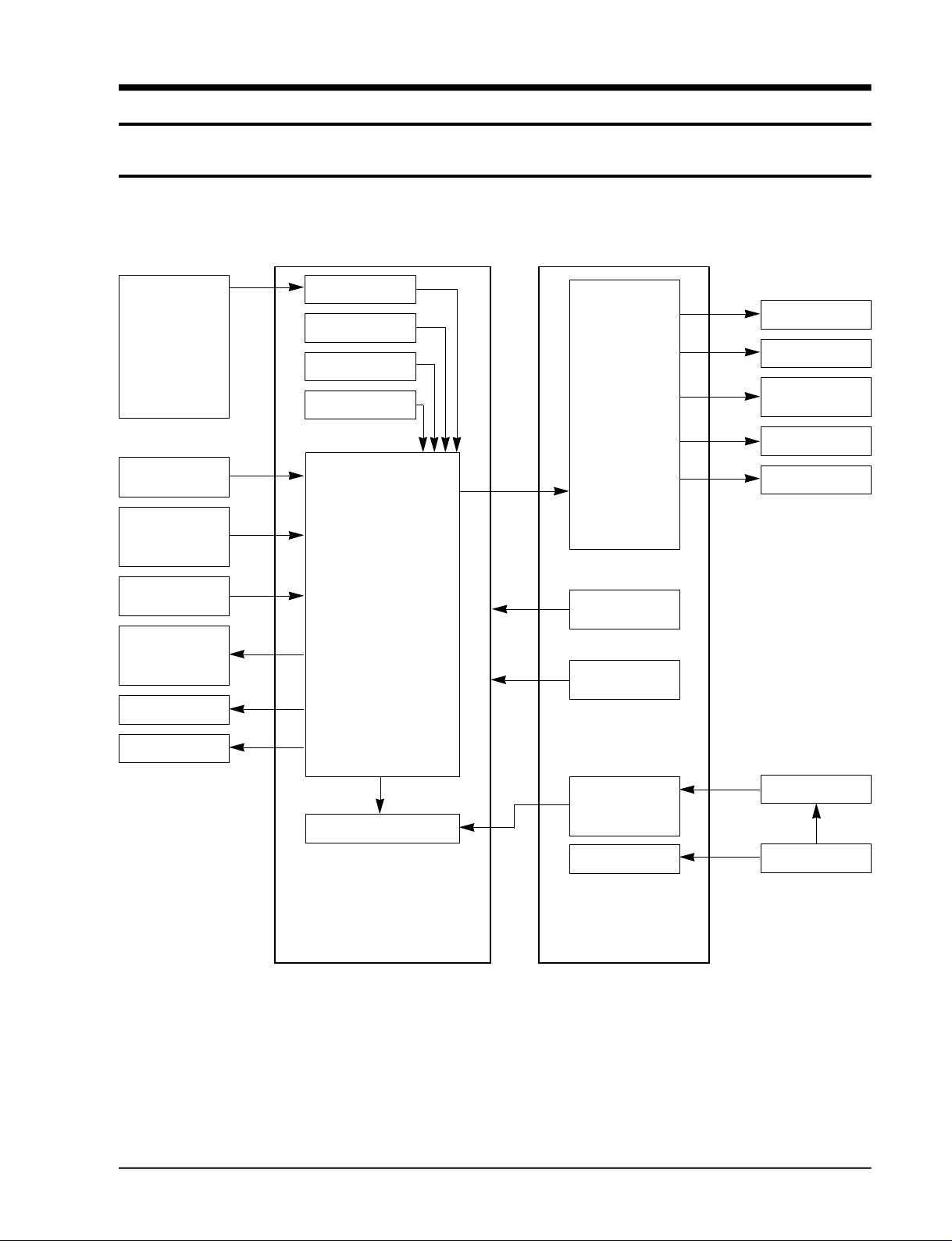
7-1 Micro Computer Block Diagram
Receiver module
Remote
Cotroller
Room temperature
sensor
Indoor EVAP.
t e m p e r a t u re sensor
KEY Scan
RESET Circuit
Oscillation Circuit
Load circuit
Compressor
Indoor fan motor
Panel shutter
motor
Outdoor fan motor
4-way valve
Panel shutter
sensor
Outdoor COND.
t e m p e r a t u re sensor
Up, Down motor
Right, Left motor
MICOM
VF-DISPLAY
ASS’Y MAIN PCB
Power circuit
(+5V)
Power circuit
(+12V)
Power circuit
(-20V)
AC 4.4V
Power circuit
ASS’Y SUB PCB
TRANSFORMER
AC 220~240V
7-1
Page 2
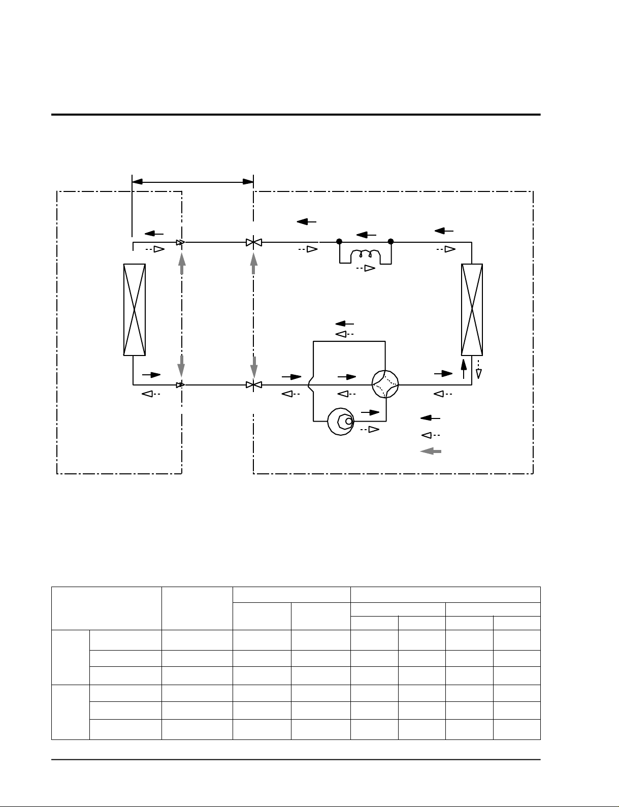
7-2 Refrigerating Cycle Block Diagram
INDOOR UNIT OUTDOOR UNIT
Allowavle pipe length:Maximum 15m
Allowable pipe drop distance:Maximum 10m
Check valve
Capillary tube
Compressor
Heat
exchanger
(Condenser)
4-way valve
Cooling
Heating
Gas leak check point
Capillary tube
Heat
exchanger
(Evaporator)
3-way valve
Liquid side
Gas side
3-way valve
* Amount of refilling per extension length of 1m;
When extending the pipe length by more than 5m, 40g of R-22 refrigerant should be refilled per
extension length of 1m.
Refrigerating cycle temperature and pressure
STD Pressure
Operating Condition
(kg/cm2G)
(GAS SIDE)
4.5~5.5
6.5~7.5
3~4
18.5~20.5
-
-
Cooling
Heating
Standard
Max over load
Low temp
Standard
Max over load
Deice
7-2
Piping Temp. Use Temp. Condition (°C)
T1 T2
40~45
50~55
30~35
32~36
36~40
28~32
9~12
14~18
1~4
65~75
70~80
40~45
Indoor Outdoor
DB
27
32
21
20
27
20
WB WBDB
19
23
16
-
-
-
35
43
21
21
24
26
16
7
6
16
2
1
Page 3

M E M O
7-3
 Loading...