

Page 1
Level
7.
Assembling
Repair
2
1
Connect the Main Camera connector.
1)
2
After pressing Connector once,Check the connect
1)
status
2
Place LCD starting from the Under
1)
side of Front and push the outline of LCD
with hand lightly to attach it completely
Open TSP connector on LCD and
2)
insert TSP FPCB alining with guide line
adhere insulating tape according to the
3)
TSP IC guide line and press it gently and
evenly
1
Don't touch with FPCB contact point
1)
Press evenly to the entire actuator.
2,3
,
LCD FPCB insert the right of the central hole
1)
3
by BRACKET. And then Assemble and
BRACKET FRONT ASS'Y.
When assembling the BRACKET,be careful to avoiding
1)
damage on TOUCH KEY connectors.
4
Beware of VGA CAMERA's direction when assembling,
1)
and push the VGA Camera rubber after assembling.
7-1
Place VGA CAMERA on it's position on
1)
BRACKET.
Assemble VGA CAMERA RUBBER on it's
2)
position guided by RIBs.
SAMSUNG Proprietary-Contents may change without notice
This Document can not be used without Samsung's authorization
Page 2
Level2Repair
7.
5
Connect the LCD FPCB CONNECTOR
1)
6
After EAR JACK FPCB put aside by hand,
1)
Place PBA on it's position on BRACKET.
And then Connect the Ear jack FPCB
When assembling the LCD connector,The upper and
1)
lower connector on the back of the PBA will be placed
7
1) After fixing to hook pressing PBA vertically,
Place Motor on inside slot of BRACKET
Assemble
2)
CONNECTOR.
1
CAMERA&SUB KEY
5M
2
Be careful the interference of EAR JACK connector
1)
and Put the Connector once.
After guise inspection of REAR, Assembling
1)
8
Rear perpendicular to the Front ass'y
After guise inspection of COVER TOP,
2)
Assembling Cover Top perpendicular at the
top of the FRONT
2
1
After assembling, Press the connector once for avoiding
1)
lift status
SAMSUNG Proprietary-Contents may change without notice
This Document can not be used without Samsung's authorization
7-2
Assembly with pressing the rear case around
1)
Mega CAMERA.
5
Page 3

Level2Repair
7.
Screw2point of the top
1)
9
Screw6point of the rear case.
2)
Torque
1.0 ~1.2
1) Must assemble 2 parts of upper screws ahead
:
Kgf·cm
7-3
SAMSUNG Proprietary-Contents may change without notice
This Document can not be used without Samsung's authorization
Page 4

Level2Repair
7.
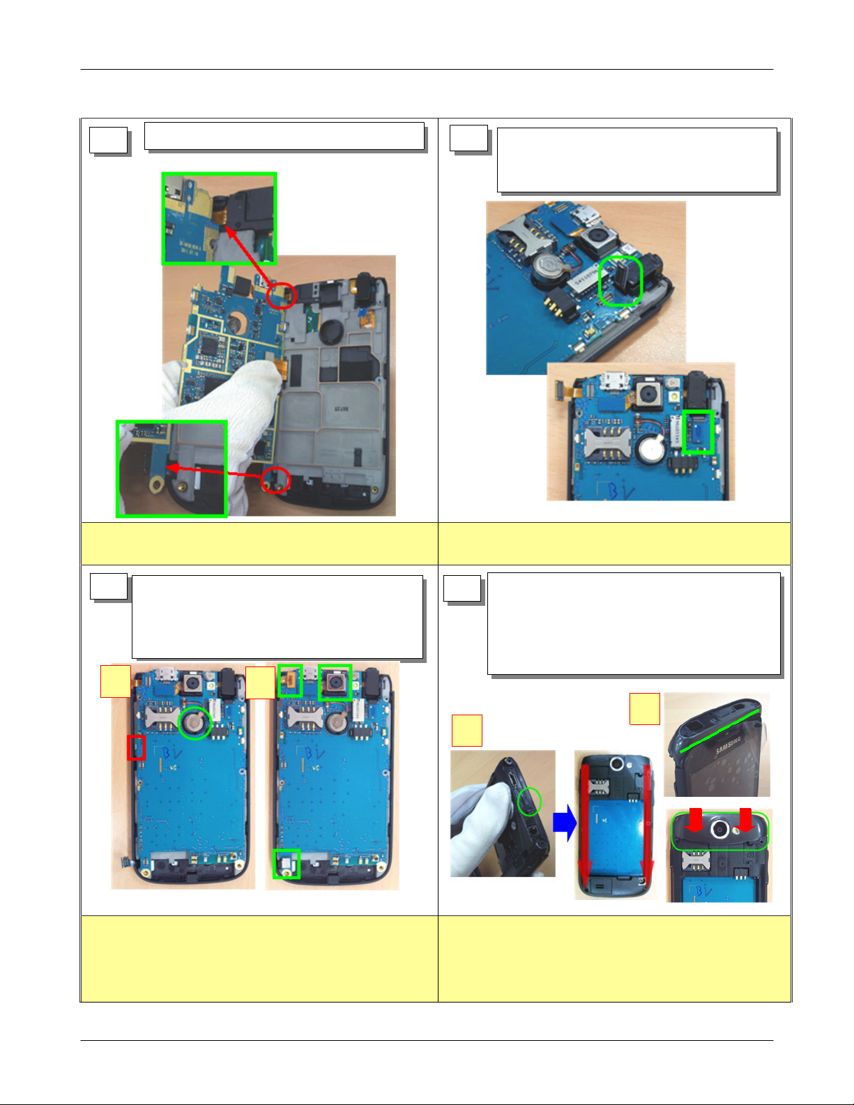
Disassembling
1
1
Unscrew without causing the damage or scratches on
1)
the case.
Unscrew6screws of back panel
1)
Unscrew2screws of top deco
2)
2
2
If you use any tool to disassemble, be careful to avoid
1)
to damage or scratch on the case.
Pull back the rear case with holding bottom
1)
side of battery.
Disassemble connectors of Camera and
1)
3
Touch Key.
Disassemble connectors of Motor, Earjack
2)
FPCB
When dismantle the camera connector, be careful to
1)
avoiding damage on ANT connectors.
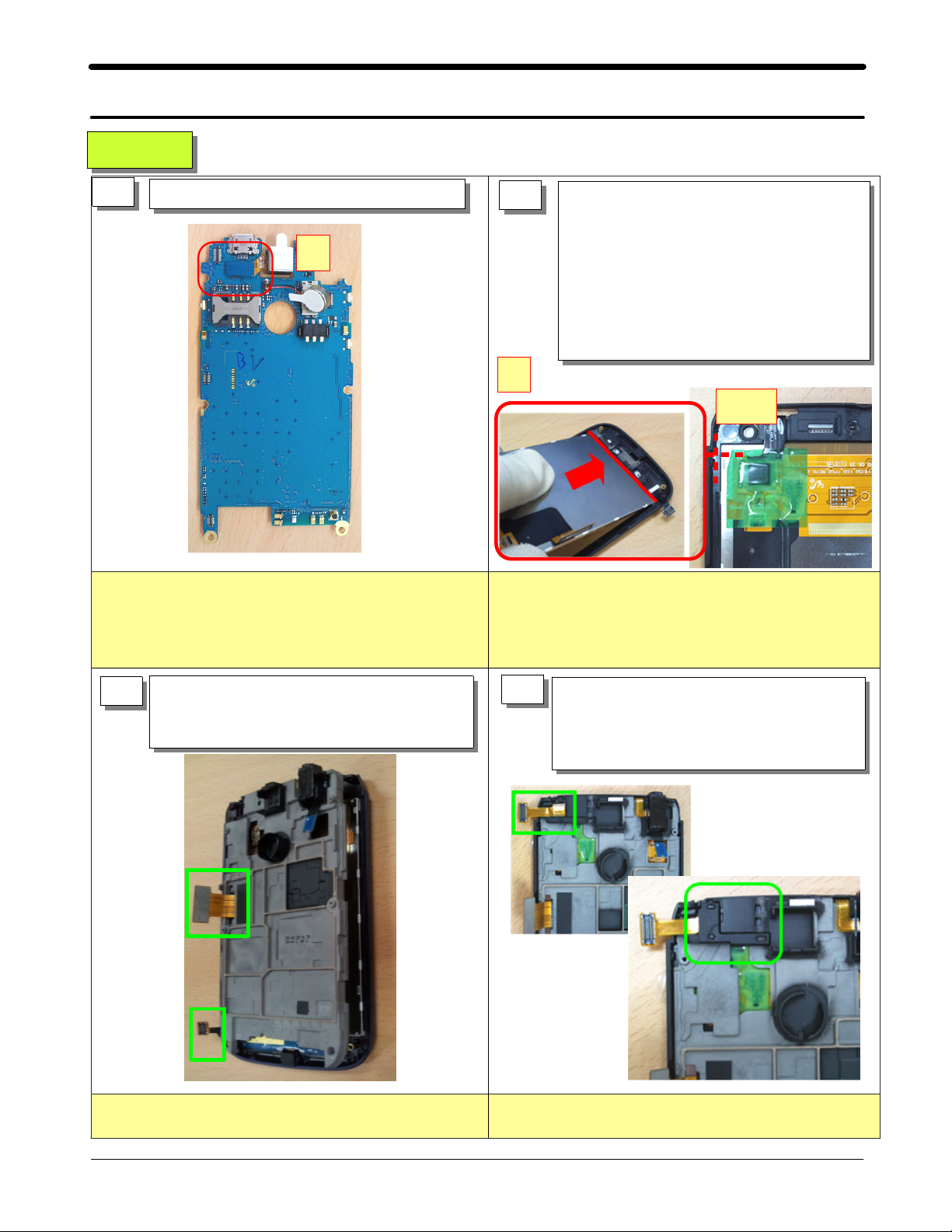
Disassemble connectors of LCD FPCB
1)
4
Be careful not to climb on PBA of VGA
※
Camera&TOUCH KEY FPCB connetctor
If you use tools to disassemble, avoid touching the
1)
FPCB.
7-4
SAMSUNG Proprietary-Contents may change without notice
This Document can not be used without Samsung's authorization
Page 5

Level2Repair
7.
5 6
Be careful to avoid damaging antenna contacts when
1)
Disassemble the Rubber of VGA Camera
1)
hold tha PBA.
Micro USB connector overlaps with bottom of front
2)
case. so don't pull the PBA up vertically.
Disassemble the LCD BRACKE
1)
When dismantle the BRACKET,be careful to avoiding
1)
T
damage on TOUCH KEY connectors.
7
Remove the Insulation Tape from TSP IC
1)
on the Front
Lift up from the bottom of the LCD FRONT,
1)
8
Pressing the side of the LCD and then
separation LCD
If you use any tool to disassemble, be careful to avoid
1)
to damage on the parts
Be careful not to press the LCD FPCB&Part
2)
7-5
SAMSUNG Proprietary-Contents may change without notice
This Document can not be used without Samsung's authorization
 Loading...