

Page 1
DIGITAL HOME
CINEMA SYSTEM
HT-THX22
HT-THX25
COMPACT
DIGITAL AUDIO
GB
Instruction Manual
AH68-01660E
REV: 01
AH68-01978B
Page 2
GB
3
Precautions
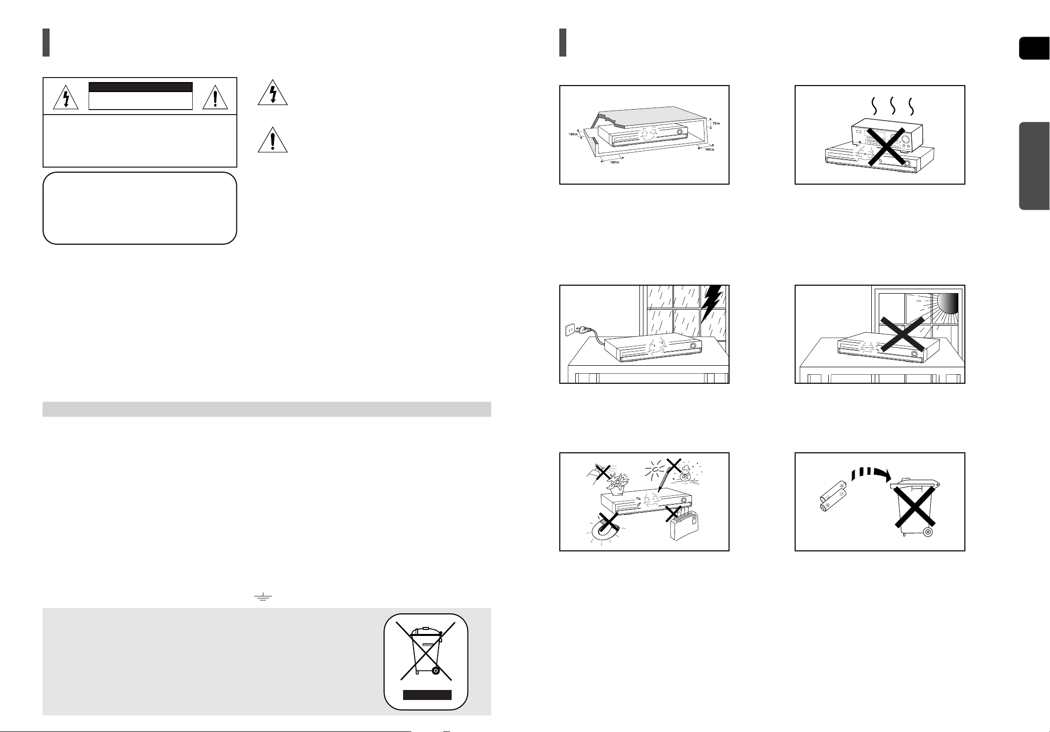
Ensure that the AC power supply in your house complies with the identification sticker located on the back of your player. Install your player horizontally, on a suitable base (furniture), with enough space around it for ventilation (7.5~10cm). Make sure the ventilation slots are
not covered. Do not stack anything on top of the player. Do not place the player on amplifiers or other equipment which may become hot.
Before moving the player, ensure the disc tray is empty. This player is designed for continuous use. Switching off the DVD player to the
stand-by mode does not disconnect the electrical supply. In order to disconnect the player completely from the power
supply, remove the main plug from the wall outlet, especially when left unused for a long period of time.
Protect the player from moisture (i.e. vases) , and excess heat
(e.g.fireplace) or equipment creating strong magnetic or electric fields
(i.e.speakers...). Disconnect the power cable from the AC supply if the
player malfunctions. Your player is not intended for industrial use.
Use of this product is for personal use only.
Condensation may occur if your player or disc has been stored in cold
temperatures.
If transporting the player during the winter, wait approximately 2 hours
until the unit has reached room temperature before using.
During thunderstorms, disconnect the AC main plug from
the wall outlet.
Voltage peaks due to lightning could damage the unit.
Do not expose the unit to direct sunlight or other heat sources.
This could lead to overheating and malfunction of the unit.
The batteries used with this product contain chemicals that are
harmful to the environment.
Do not dispose of batteries in the general household trash.
PREPARATION
2
Safety Warnings
Wiring the Main Power Supply Plug (UK Only)
IMPORTANT NOTICE
The main lead on this equipment is supplied with a moulded plug incorporating a fuse. The value of the fuse is indicated on the pin face of the plug
and if it requires replacing, a fuse approved to BS1362 of the same rating must be used.
Never use the plug with the fuse cover removed. If the cover is detachable and a replacement is required, it must be of the same colour as the fuse
fitted in the plug. Replacement covers are available from your dealer.
If the fitted plug is not suitable for the power points in your house or the cable is not long enough to reach a power point, you should obtain
a suitable safety approved extension lead or consult your dealer for assistance.
However, if there is no alternative to cutting off the plug, remove the fuse and then safely dispose of the plug. Do not connect the plug to
a main socket as there is a risk of shock hazard from the bared flexible cord.
Never attempt to insert bare wires directly into a main socket. Aplug and fuse must be used at all times.
IMPORTANT
The wires in the main lead are coloured in accordance with the following code:– BLUE = NEUTRAL BROWN = LIVE
As these colours may not correspond to the coloured markings identifying the terminals in your plug, proceed as follows:–
The wire coloured BLUE must be connected to the terminal marked with the letter N or coloured BLUE or BLACK.
The wire coloured BROWN must be connected to the terminal marked with the letter L or coloured BROWN or RED.
WARNING : DO NOT CONNECT EITHER WIRE TO THE EARTH TERMINAL WHICH IS MARKED WITH THE
LETTER E OR BY THE EARTH SYMBOL , OR COLOURED GREEN OR GREEN AND YELLOW.
RISK OF ELECTRIC SHOCK.
DO NOT OPEN
TO REDUCE THE RISK OF ELECTRIC SHOCK,
DO NOT REMOVE REAR COVER (or BACK).
NO USER SERVICEABLE PARTS INSIDE.
REFER SERVICING TO QUALIFIED SERVICE
PERSONNEL.
CAUTION
This symbol indicates “dangerous voltage” inside
the product that presents a risk of electric shock
or personal injury.
This symbol indicates important instructions
accompanying the product.
CLASS 1 LASER PRODUCT
This Compact Disc player is classified as a CLASS 1
LASER product.
Use of controls, adjustments or performance of procedures
other than those specified herein may result in hazardous
radiation exposure.
CAUTION :
INVISIBLE LASER RADIATION WHEN OPEN AND
INTERLOCKS DEFEATED, AVOID EXPOSURE TO BEAM.
WARNING : To reduce the risk of fire or electric shock, do not expose this appliance to rain or moisture.
CAUTION : TO PREVENT ELECTRIC SHOCK, MATCH WIDE BLADE OF PLUG TO WIDE SLOT, FULLY INSERT.
•
This apparatus shall always be connected to a AC outlet with a protective grounding connection.
•
To disconnect the apparatus from the mains, the plug must be pulled out from the mains socket, therefore the mains
plug shall be readily operable.
CAUTION
•
Apparatus shall not be exposed to dripping or splashing and no objects filled with liquids, such as vases,
shall be placed on the apparatus.
•
The Mains plug is used as a disconnect device and shall stay readily operable at any time.
CLASS 1 LASER PRODUCT
KLASSE 1 LASER PRODUKT
LUOKAN 1 LASER LAITE
KLASS 1 LASER APPARAT
PRODUCTO LASER CLASE 1
This marking shown on the product or its literature, indicates that it should not be
disposed with other household wastes at the end of its working life.
To prevent possible harm to the environment or human health from uncontrolled waste
disposal, please separate this from other types of wastes and recycle it responsibly to
promote the sustainable reuse of material resources.
Household users should contact either the retailer where they purchased this product,
or their local government office, for details of where and how they can take this item
for environmentally safe recycling.
Business users should contact their supplier and check the terms and conditions
of the purchase contract.
This product should not be mixed with other commercial wastes for disposal.
Phones
Page 3

GB
5
PREPARATION
Contents
PREPARATION
Safety Warnings ............................................................2
Precautions....................................................................3
Features.........................................................................4
Notes on Discs ..............................................................6
Description.....................................................................8
CONNECTIONS
Connecting the Speakers............................................12
Speaker Installation.....................................................14
Connecting the Optional Wireless
Receiving Amplifier......................................................15
Connecting the Video Out to your TV .........................18
HDMI Function.............................................................20
Connecting Audio from External Components............21
Connecting the FM Antenna........................................22
OPERATION
Before Reading the User's Manual .............................23
Before Using Your Home Theater...............................24
Disc Playback..............................................................25
MP3/WMA-CD Playback .............................................26
JPEG File Playback.....................................................27
DivX Playback .............................................................28
Using the Playback Function .......................................30
Displaying Disc Information......................................30
Checking the Remaining Time..................................31
Fast Playback...........................................................31
Slow Playback ..........................................................31
Skipping Scenes/Songs ............................................32
Repeat Playback.......................................................33
To Select a Repeat Playback Mode in the Disc
Information Screen ...................................................33
A-B Repeat Playback................................................34
Step Function............................................................34
Angle Function ..........................................................35
Zoom (Screen Enlarge) Function .............................35
EZ VIEW Function....................................................36
Audio Language Selection Function .........................37
Subtitle Language Selection Function......................37
Moving Directly to a Scene/Song .............................38
Using the Disc Menu ................................................39
Using the Title Menu.................................................39
Playing Media Files using the USB Host feature ........40
SETUP
Settings........................................................................42
Setting the Language................................................42
Setting TV Screen Type............................................43
Setting Parental Controls (Rating Level)..................44
Setting the Password................................................44
Setting the Wallpaper ...............................................45
To Select One of the 3 Wallpaper Settings
you've made..............................................................45
DivX (R) Registration................................................46
Setting the Speaker Mode........................................46
Setting the Delay Time.............................................47
Setting the Test Tone................................................48
Setting the Audio.......................................................49
Setting the DRC (Dynamic Range Compression)....50
Setting the AV SYNC................................................50
Setting the HDMI Audio............................................51
Sound Field (DSP)/EQ Function .................................52
Dolby Pro Logic II Mode..............................................53
Dolby Pro Logic II Effect..............................................54
MISCELLANEOUS
Listening to Radio........................................................55
About RDS broadcasting.............................................57
Convenient Functions ..................................................59
Operating a TV with the Remote Control....................60
Troubleshooting...........................................................62
Cautions on Handling and Storing Discs.....................64
Language Code List ....................................................65
USB Host Feature Supported Products ......................66
Specifications...............................................................67
4
Features
Multi-Disc Playback & FM Tuner
The HT-THX22/HT-THX25 combines the convenience of multi-disc playback capability, including DVD-VIDEO, CD,
MP3-CD, WMA-CD, DivX, CD-R/RW, and DVD R/RW, with a sophisticated FM tuner, all in a single player.
Dolby Pro Logic II
Dolby Pro Logic II is a form of multi-channel audio signal decoding technology that improves upon existing Dolby Pro
Logic.
DTS (Digital Theater Systems)
DTS is an audio compression format developed by Digital Theater Systems Inc. It delivers full-frequency
5.1 channel sound.
Power Saving Function
The HT-THX22/HT-THX25 will automatically shut off after 20 minutes in Stop mode.
TV Screen Saver Function
If the main unit remains in Stop mode for 3 minutes, the Samsung logo appears on the TV screen.
The HT-THX22/HT-THX25 will automatically switch to the Power Saving mode after 20 minutes in the Screen Saver mode.
Customized TV Screen Display
The HT-THX22/HT-THX25 allows you to select your favorite image during JPEG or DVD playback and set it as your
background wallpaper.
HDMI
HDMI transmits DVD video and audio signals simultaneously, and provides a clearer picture.
USB Host support
You can enjoy media files such as pictures, movies and music saved on an MP3 player, digital camera or USB memory
stick by connecting the storage device to the USB port of the Home Theater.
Page 4
GB
7
CD-R Discs
•
Some CD-R discs may not be playable depending on the disc recording device (CD-Recorder or PC) and the condition of
the disc.
•
Use a 650MB/74 minute CD-R disc.
Do not use CD-R discs over 700MB/80 minute as they may not be played back.
•
Some CD-RW (Rewritable) media, may not be playable.
•
Only CD-Rs that are properly "closed" can be fully played. If the session is closed but the disc is left open, you may not
be able to fully play the disc.
CD-R JPEG Discs
•
Only files with the "jpg" extensions can be played.
•
If the disc is not closed, it will take longer to start playing and not all of the recorded files may be played.
•
Only CD-R discs with JPEG files in ISO 9660 or Joliet format can be played.
•
JPEG file names should be 8 characters or less in length and contain no blank spaces or special characters (. / = +).
•
Only a consecutively written multisession disc can be played. If there is a blank segment in the multisession disc,
the disc can be played only up to the blank segment.
•
A maximum of 9,999 images can be stored on a single CD.
•
When playing a Kodak/Fuji Picture CD, only the JPEG files in the picture folder can be played.
•
Picture discs other than Kodak/Fuji Picture CDs may take longer to start playing or may not play at all.
CD-R MP3 Discs
•
Only CD-R discs with MP3 files in ISO 9660 or Joliet format can be played.
•
MP3 file names should be 8 characters or less in length and contain no blank spaces or special characters (. / = +).
•
Use discs recorded with a compression/decompression data rate greater than 128Kbps.
•
Only files with the "mp3" and extensions can be played.
•
Only a consecutively written multisession disc can be played. If there is a blank segment in the Multisession disc,
the disc can be played only up to the blank segment.
•
If the disc is not closed, it will take longer to begin playback and not all of the recorded files may be played.
•
For files encoded in Variable Bit Rate (VBR) format, i.e. files encoded in both low bit rate and high bit rate
(e.g., 32Kbps ~ 320Kbps), the sound may skip during playback.
•
A maximum of 500 tracks can be played per CD.
•
A maximum of 300 folders can be played per CD.
DVD R/RW, CD-R/RW DivX Discs
•
Since this product only provides encoding formats authorized by DivX Networks, Inc., a DivX file created by the user
might not play.
•
Software updates for incompatible formats are not supported.
(Example : QPEL, GMC, resolution higher than 800 x 600 pixels, etc.)
•
Sections with a high frame rate might not be played while playing a DivX file.
•
For more information about the formats authorized by DivX Networks, Inc., please visit "www.divxnetworks.net".
This product does not support Secure (DRM) Media files.
Disc Recording Format
PREPARATION
6
Notes on Discs
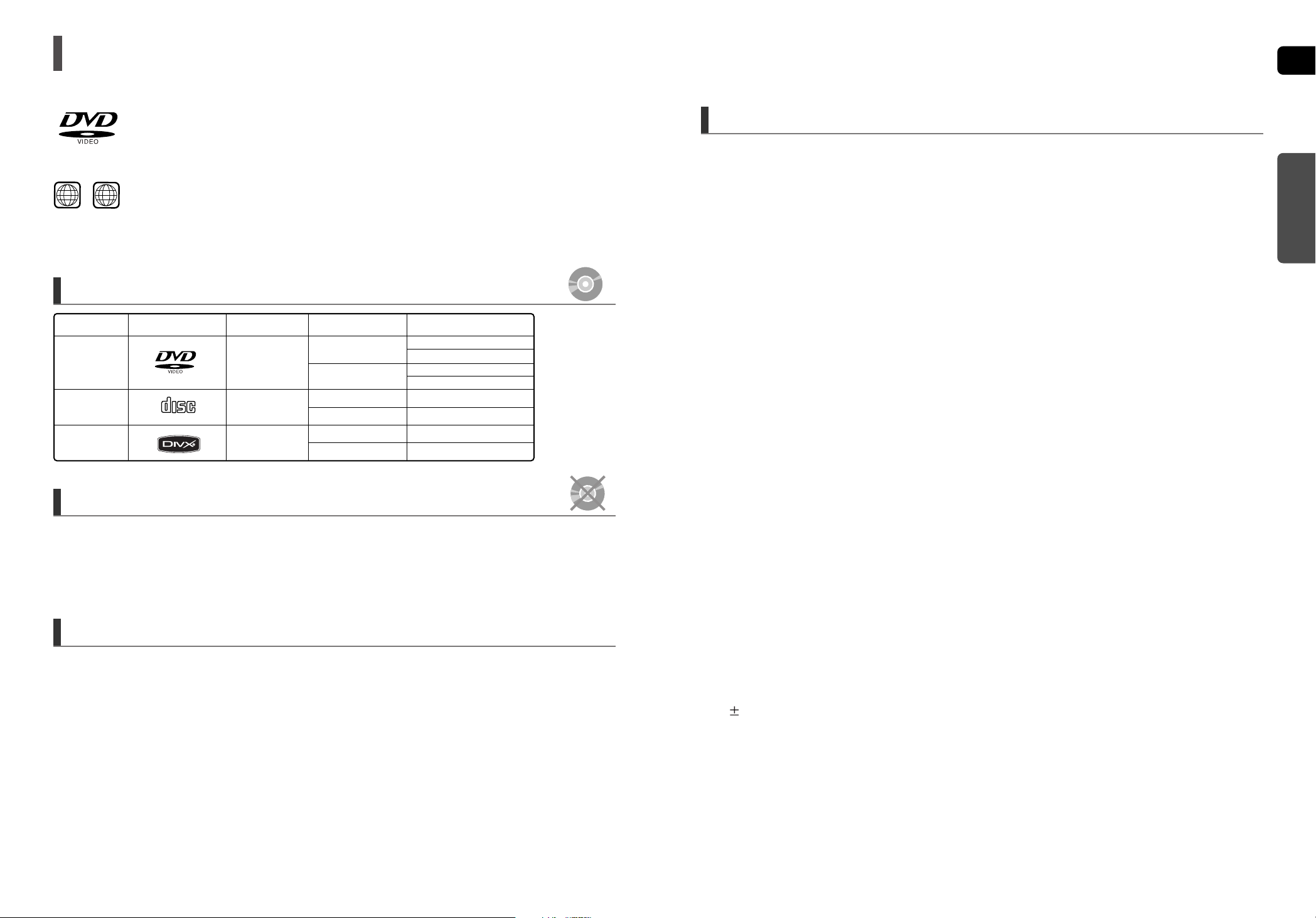
DVD (Digital Versatile Disc) offers fantastic audio and video, thanks to Dolby Digital
surround sound and MPEG-2 video compression technology. Now you can enjoy these
realistic effects in the home, as if you were in a movie theater or concert hall.
DVD players and the discs are coded by region. These regional codes must match in order
for the disc to play. If the codes do not match, the disc will not play.
The Region Number for this player is given on the rear panel of the player.
(Your DVD player will only play DVDs that are labeled with identical region codes.)
1 6
~
•
LD, CD-G, CD-I, CD-ROM and DVD-ROM discs cannot be played on this player.
If such discs are played, a <WRONG DISC FORMAT> message appears on the TV screen.
•
DVD discs purchased abroad may not play on this player.
If such discs are played, a <CAN'T PLAY THIS DISC PLEASE, CHECK REGION CODE> message
appears on the TV screen.
•
Many DVD discs are encoded with copy protection. Because of this, you should only connect your
DVD player directly to your TV, not to a VCR. Connecting to a VCR results in a distorted
picture from copy-protected DVD discs.
•
This product incorporates copyright protection technology that is protected by methods claims of certain U.S.
patents and other intellectual property rights owned by Macrovision Corporation and other rights owners.
Use of this copyright protection technology must be authorized by Macrovision Corporation, and is intended
for home and other limited viewing uses only unless otherwise authorized by Macrovision Corporation.
Reverse engineering or disassembly is prohibited.
Playable Discs
Do not use the following types of disc!
Copy Protection
Mark (Logo)
Audio + Video
DVD-VIDEO
AUDIO-CD
DivX
12cm
Approx. 240 min. (single-sided)
Approx. 480 min. (double-sided)
Approx. 80 min. (single-sided)
Approx. 160 min. (double-sided)
74 min.
20 min.
74 min.
20 min.
8cm
12cm
8cm
12cm
8cm
Audio
Audio + Video
Recorded Signals
Disc Type Disc Size Max. Playing Time
COMPACT
DIGITAL AUDIO
Page 5
GB
9
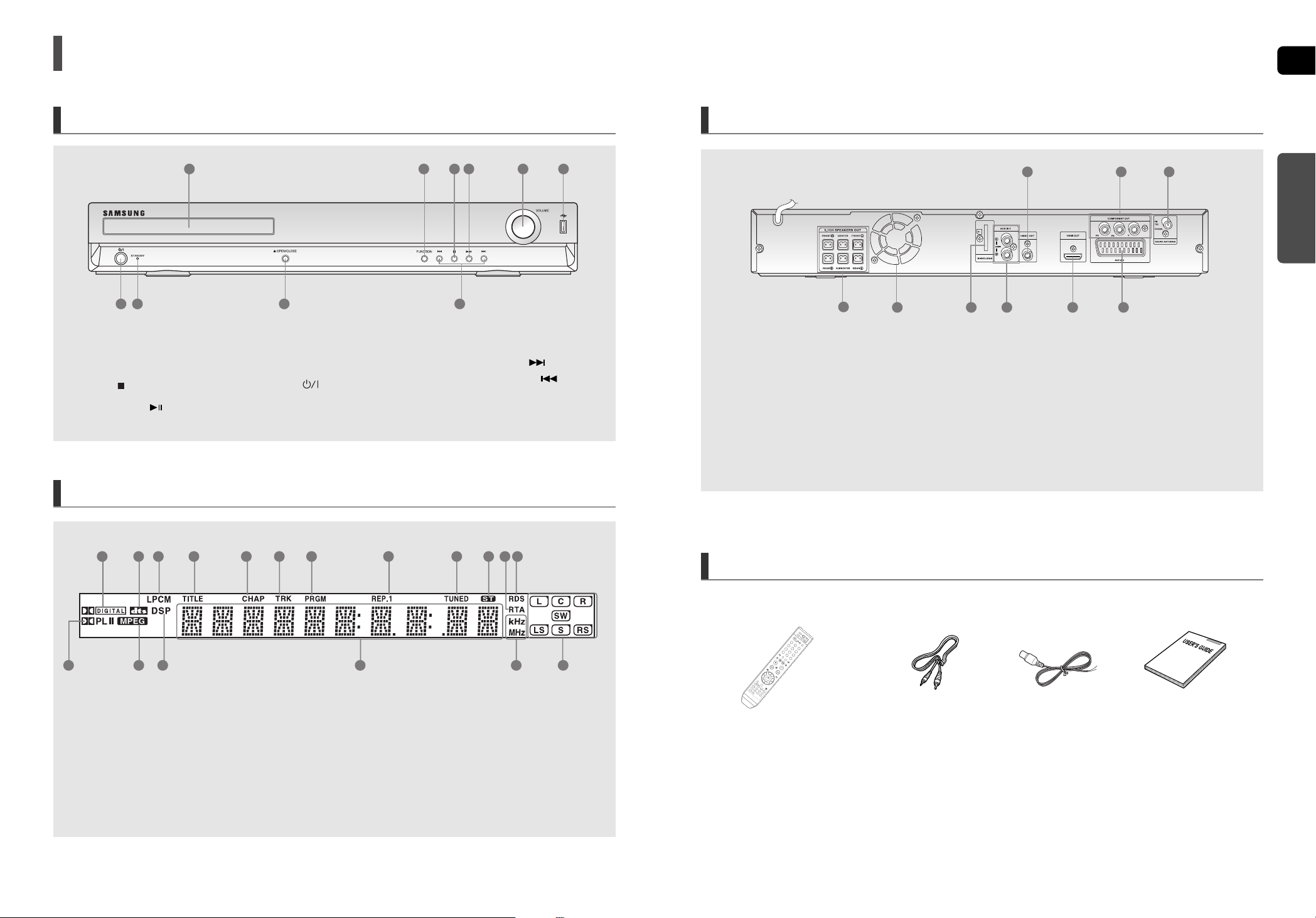
Rear Panel
Accessories
Video CableRemote Control
FM Antenna
User's Manual
1. Video Output Jack
Connect the TV's Video Input jack (VIDEO IN) to
the VIDEO OUT jack.
2. Component Video Output Jacks
Connect a TV with component video inputs to these jacks.
3. FM 75Ω COAXIAL Jack
4. 5.1 Channel Speaker Output Connectors
5. Cooling Fan
6. TX Card Connection (WIRELESS)
7. AUX IN 2 Jacks
8. HDMI Output Jack
9. SCART Jack
Connect to a TV with scart input jack.
9
6
4
1
7 8
32
PREPARATION
8
Description
Front Panel
Display
1. DOLBY DIGITAL indicator
2. DTS Disc indicator
3. LINEAR PCM indicator
4. TITLE indicator
5. CHAPTER indicator
6. TRACK indicator
7. PROGRAM indicator
8. REPEAT indicator
9. TUNER indicator
10. STEREO indicator
11. RTAindicator
12. RDS indicator
13. PRO LOGIC indicator
14. MPEG indicator
15. DSP indicator
16. System Status Display
17. RADIO FREQUENCY indicator
18. SPEAKER indicator
7
8
9 10 11 125 62 31 4
1815 16 1713 14
1. Disc Tray
2. Function button
3. Stop ( ) button
4. Play/Pause ( ) button
5. Volume Control
6. USB Connector
7. Power ( ) button
8. Standby indicator
9. Open/Close button
10.Tuning Up & Skip ( ) button
Tuning Down & Skip ( ) button
1
7 8
3 4
9
10
2 5 6
5
Page 6
GB
11
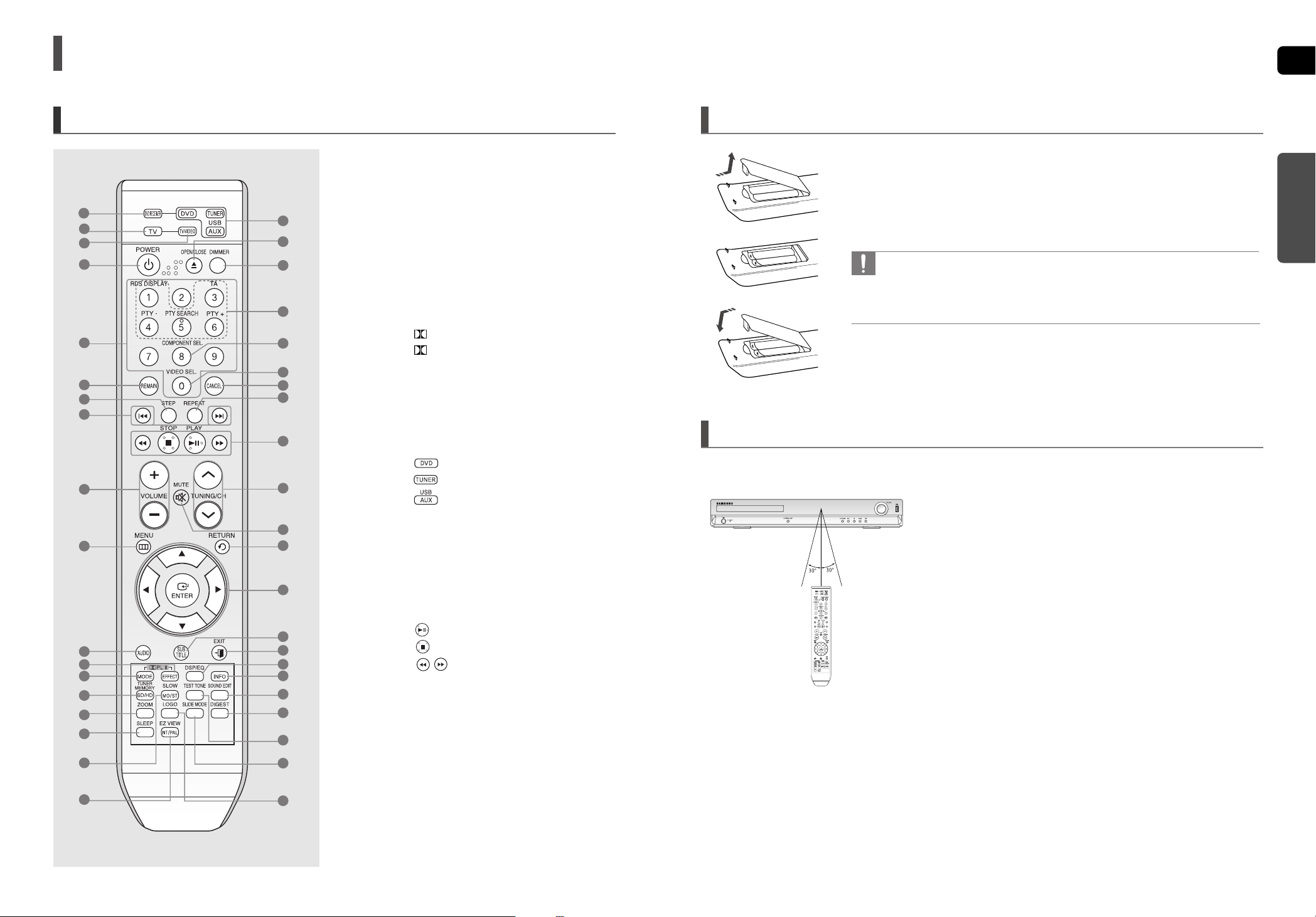
1 Remove the battery cover in the direction of the arrow.
2 Insert two 1.5V AAA batteries, paying attention to the correct polarities
(+ and –).
3 Replace the battery cover.
Follow these precautions to avoid leaking or cracking cells:
• Place batteries in the remote control so they match the polarity : (+) to (+) and (–) to (–).
• Use the correct type of batteries. Batteries that look similar may differ in voltage.
• Always replace both batteries at the same time.
• Do not expose the batteries to heat or a flame.
Insert Remote Batteries
PREPARATION
Operation Range of the Remote Control
The remote control can be used up to approximately 23 feet (7 meters) in a straight line. It can also be
operated at a horizontal angle of up to 30° from the remote control sensor.
10
Description (Con’t)
Remote Control
1. DVD RECEIVER button
2. TV button
3. TV/VIDEO button
4. POWER button
5. Number (0~9) buttons
6. REMAIN button
7. STEP button
8. Tuning Preset/CD Skip buttons
9. VOLUME button
10.MENU button
1 1. AUDIO button
12. PL II EFFECT button
13. PL II MODE button
14.TUNER MEMORY,
SD(Standard Definition)/HD(High Definition) button
15.ZOOM button
16.SLEEP button
17.SLOW, MO/ST button
18. EZ VIEW, NT/PAL button
19. DVD button
TUNER button
USB, AUX button
20.OPEN/CLOSE button
21.DIMMER button
22.RDS Selection buttons
23.COMPONENT SEL. button
24.VIDEO SEL. button
25.CANCEL button
26. REPEAT button
27. PLAY/PAUSE button
STOP button
SEARCH buttons
28.TUNING/CH button
29. MUTE button
30. RETURN button
31. Cursor/ENTER button
32. SUBTITLE button
33. EXIT button
34. DSP/EQ button
35.INFO button
36. SOUND EDIT button
37. DIGEST button
38. TEST TONE button
39. SLIDE MODE button
40. LOGO button
1
6
7
8
3
4
14
15
16
17
18
9
10
13
12
2
11
5
19
24
25
26
27
29
28
30
32
33
34
35
36
37
38
39
40
31
21
20
22
23
Page 7
GB
CONNECTIONS
13
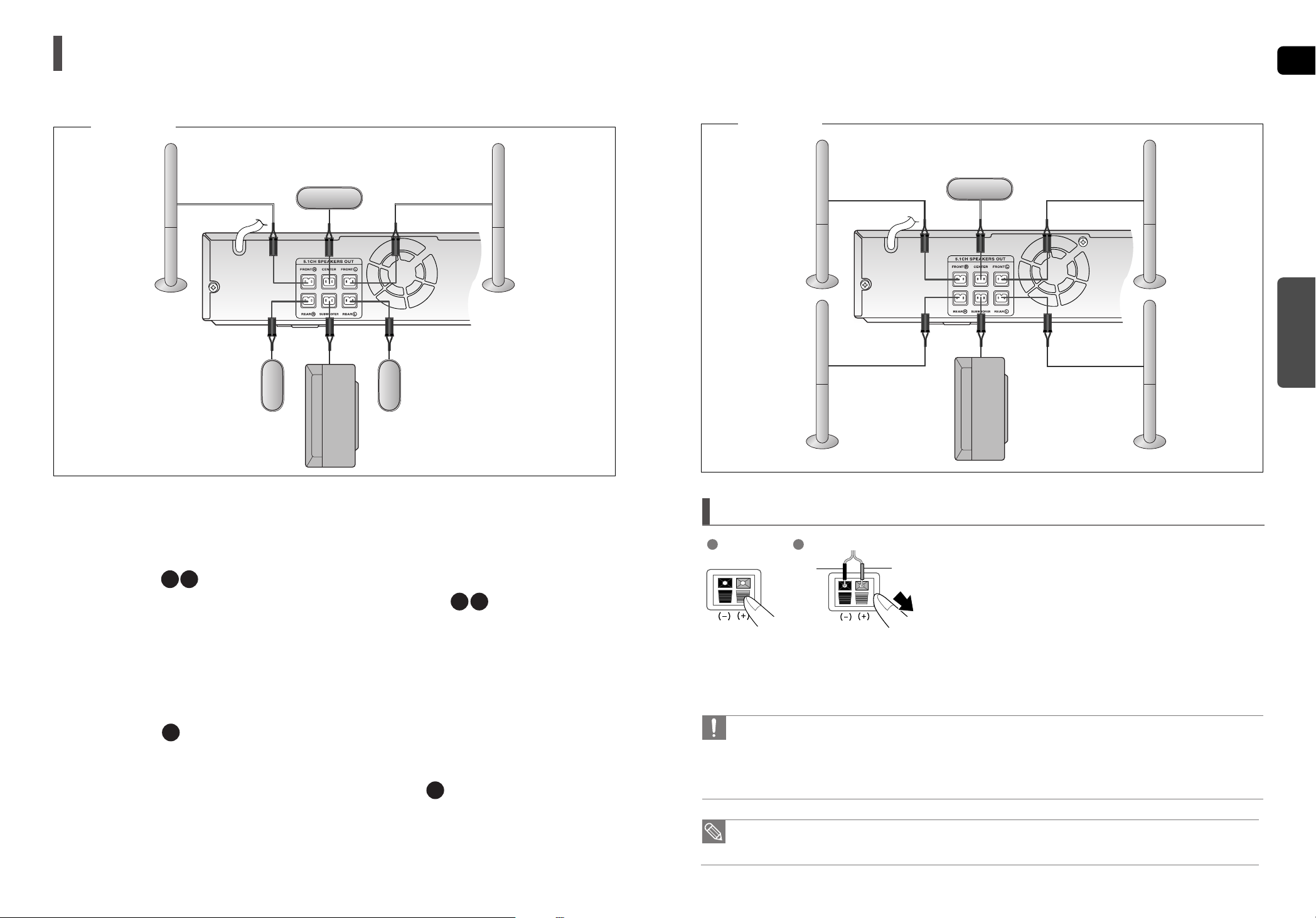
• If you place a speaker near your TV set, screen color may be distorted because of the magnetic field generated
by the speaker. If this occurs, place the speaker away from your TV set.
1 Press down the terminal tab on the back of the speaker.
2 Insert the black wire into the black terminal (–) and the red wire
into the red (+) terminal, and then release the tab.
3 Connect the connecting plugs to the back of the Home Theater.
• Make sure the colors of the speaker terminals match the colors of
the connecting plugs.
• Do not let children play with or near the speakers. They could get hurt if a speaker falls.
• When connecting the speaker wires to the speakers, make sure that the polarity (+/–) is correct.
• Keep the subwoofer speaker out of reach of children so as to prevent children from inserting their hands or alien
substances into the duct (hole) of the subwoofer speaker.
• Do not hang the subwoofer on the wall through the duct (hole).
1 2
Connecting the Speakers
Black Red
HT-THX25
Front Speaker (R)
Rear Speaker (R)
Subwoofer
Center Speaker
Front Speaker (L)
Rear Speaker (L)
12
Connecting the Speakers
Rear Speakers
•
Place these speakers behind your listening position.
•
If there isn't enough room, place these speakers so they face
each other.
•
Place them about 60 to 90cm (2 to 3feet) above your ear,
facing slightly downward.
*
Unlike the front and center speakers, the rear speakers are
used to handle mainly sound effects and sound will not
come from them all the time.
*
Sound will be heard from the rear speakers in
DVD 5.1-CH or Dolby Pro Logic II mode only.
Front Speakers
•
Place these speakers in front of your listening position, facing
inwards (about 45°) toward you.
•
Place the speakers so that their tweeters will be at the same
height as your ear.
•
Align the front face of the front speakers with the front face of
the center speaker or place them slightly in front of the center
speakers.
Center Speaker
•
It is best to install it at the same height as the front speakers.
•
You can also install it directly over or under the TV.
Position of the DVD Player
•
Place it on a stand or cabinet shelf, or under the TV stand.
Selecting the Listening Position
The listening position should be located about 2.5 to 3 times the
distance of the TV's screen size away from the TV. Example :
For 32" TVs 2~2.4m (6~8feet)
For 55" TVs 3.5~4m (11~13feet)
Before moving or installing the product, be sure to turn off the power and disconnect the power cord.
R
L
C
SR
SL
Subwoofer
•
The position of the subwoofer is not so critical.
Place it anywhere you like.
SW
Front Speaker (R)
Rear Speaker (R)
Subwoofer
Center Speaker
Front Speaker (L)
Rear Speaker (L)
HT-THX22
Page 8
GB
CONNECTIONS
15
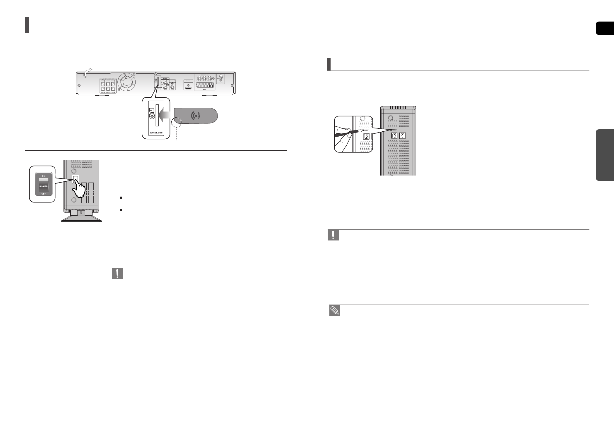
WIRELESS RECEIVER MODULE
To connect the rear speakers wirelessly, you have to purchase the wireless receiving module and
TX card from your Samsung retailer.
Connecting the Optional Wireless Receiving Amplifier
Rear Speaker (L)
Subwoofer
Center Speaker
Rear Speaker (R)
WIRELESS RECEIVER MODULE
Rear Speaker (L)
Rear Speaker (R)
HT-THX22
HT-THX25
Front Speaker (R)
Subwoofer
Center Speaker
Front Speaker (L)
Front Speaker (R)
Front Speaker (L)
When you have Purchased the Wireless Receiving Module (SWA-3000)
14
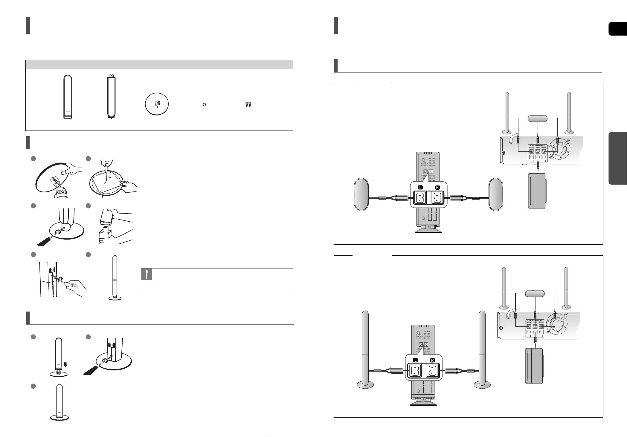
1 Connect the SPEAKER with the STAND BASE.
2 Insert the screw (B) into the hole on the rear of the speaker
using a screwdriver as shown in the illustration.
3 This is the SPEAKER successfully assembled with
the Stand Base.
How to Install the Speaker on the Stand Base
1
3
2
Speaker Installation
1 Turn the STAND upside-down and connect it to
the STAND BASE.
2 Insert two screws (A) into the two holes marked with arrows
using a screwdriver as shown in the illustration.
3 Insert a screw (B), into the hole on the rear of the Speaker
STAND.
4 Connect the assembled stand to the SPEAKER.
5 Insert another screw (B) into the hole on the rear of the
speaker using a screwdriver as shown in the illustration.
6 This is the SPEAKER successfully assembled with
the Stand.
How to Install the Speaker on the Stand
•
Make sure that the speaker is installed on a flat and stable area.
Otherwise it may be easily knocked over.
1
3 4
2
5 6
Speaker Components
Screw (B)Screw (A)STAND BASESTANDSPEAKER
With the HT-THX22front speakers and HT-THX25 front/rear speakers, you have the option of installing the speakers on
Stands, or directly to the Stand Base.
Page 9
GB
CONNECTIONS
17
• Place the wireless receiver module at the rear of the listening position. If the wireless receiver module is too close
to the main unit, some sound interruption may be heard due to interference.
• If you use a device such as a microwave oven, wireless LAN Card, Bluetooth equipment, or any other device that
uses the same frequency (2.4GHz) near the system, some sound interruption may be heard due to interference.
• The transmission distance of a radio wave is about 10m, but may vary depending on your operating environment.
If a steel-concrete wall or metallic wall is between the main unit and the wireless receiver module, the system may
not operate at all, because the radio wave cannot penetrate metal.
• When the wireless receiving module setting is complete, no sound is output from the Rear Speaker Output
Connectors on the back of the main unit.
• The wireless receiving antenna is built into the wireless receiver module. Keep the unit away from water and
moisture.
• For optimal listening performance, make sure that the area around the wireless receiver module location is clear of
any obstructions.
•
Sound will be heard from the wireless rear speakers in DVD 5.1-CH or Dolby Pro Logic II mode
only.
• In 2-CH mode, no sound will be heard from the wireless rear speakers.
Resetting the Wireless Receiving Module
Reset the system if a communication failure occurs, or if the Link indicator (blue LED) on the wireless receiver does not
light up and the "REAR CHECK" message blinks on the main unit's display.
Reset the system while the main unit and the wireless receiver module (SWA-3000) are in Power Standby mode.
1 With the main unit turned off, press and hold the remote
control's REMAIN button for 5 seconds.
■
The STANDBY LED on the front panel of the wireless receiver module
blinks.
2 With the wireless receiver module turned on, use a ball point
pen or a pair of toothpick to press the RESET button on the
back of the unit.
■
The STANDBY LED on the front panel of the wireless receiver module
blinks 2 Times.
3 Turn on the main unit.
■
The LINK LED of the wireless receiver module is lit and the Reset is
completed.
■
If Power Standby mode continues, repeat Steps 1 to 3 above.
16
1 Connect the front, center and Subwoofer speakers to the DVD Player,
reffering to pages 12~14.
2 With the DVD Player turned off, insert the TX card into the TX Card
Connection(WIRELESS) on the back of the main unit.
Hold the TX card so that the slanted side faces downward and insert the card into
the port.
The TX card enables communication between the main unit and the wireless receiver.
3 Connect the left and right rear speakers to the wireless receiving
module.
4 Plug the power cord of the wireless receiving module in the wall outlet
and switch the power switch ‘ON’.
• Do not insert a card other than the TX card dedicated for the product.
The product might be damaged or the card may not be removed easily.
• Do not insert the TX card upside down or in the reverse direction.
• Insert the TX card when the DVD Player is turned off. Inserting the card
when it is turned on may cause a problem.
• If the TX Card is inserted, sound is not output from the Rear Speaker
connectors on the main unit.
TX card
Slanted side faces down
Connecting the Optional Wireless Receiving Amplifier(Con’t)
Page 10

GB
CONNECTIONS
19
Choose one of the four methods for connecting to a TV.
Connecting the Video Out to your TV
18
Connect the supplied Video cable from the VIDEO OUT jack on the back of the DVD Player to the VIDEO IN jack on your TV.
METHOD 4 : Composite Video ....... (Good Quality)
If your television is equipped with an SCART input, connect an Scart Jack (not supplied) from the AV OUT jack on
the back panel of the main unit to the SCART IN jack on your television.
METHOD 3 : Scart ....... (Better Quality)
If your television is equipped with Component Video inputs, connect a Component video cable(not supplied) from
the Component Video Output (Pr, Pb and Y) jacks on the back of the DVD Player to the Component Video Input
jacks on your TV.
COMPONENT SELECT Function
1. With the main unit turned off, press and hold the COMPONENT SEL. button on the remote control for over 5
seconds.
• <Y Pb Pr> and<RGB> will appear in the display.
2. Press the COMPONENT SEL. button shortly to select <Y Pb Pr> to set the main unit to COMPONENT mode.
METHOD 2 : Component Video ....... (Better Quality)
METHOD 4
(supplied)
METHOD 2METHOD 3METHOD 1
1. With the main unit turned off, press and hold the COMPONENT SEL. button on the remote control for over 5 seconds.
• <Y Pb Pr> and<RGB> will appear in the display.
2. Press the COMPONENT SEL. button shortly to select <RGB> to set SCART mode.
VIDEO SELECT Function
Press and hold the VIDEO SEL. button on the remote control for over 5 seconds.
• <COMPOSITE> or <RGB> will appear in the display. At this time, press the VIDEO SEL. button shortly to select
between <COMPOSITE> and <RGB>.
• If Scart (RGB Input) is equipped for your TV, press the VIDEO SEL. button to select RGB mode.
You can get a better picture quality by using Scart setting.
• If Scart (RGB Input) is not equipped for your TV, press the VIDEO SEL. button to select COMPOSITE mode.
Connect the HDMI cable (not supplied) from the HDMI OUT jack on the back of the DVD Player to the HDMI IN
jack on your TV.
METHOD 1 : HDMI ....... (Best Quality)
• This product operates in Interlace scan mode (576i, 480i) for component output.
Page 11
GB
CONNECTIONS
2120
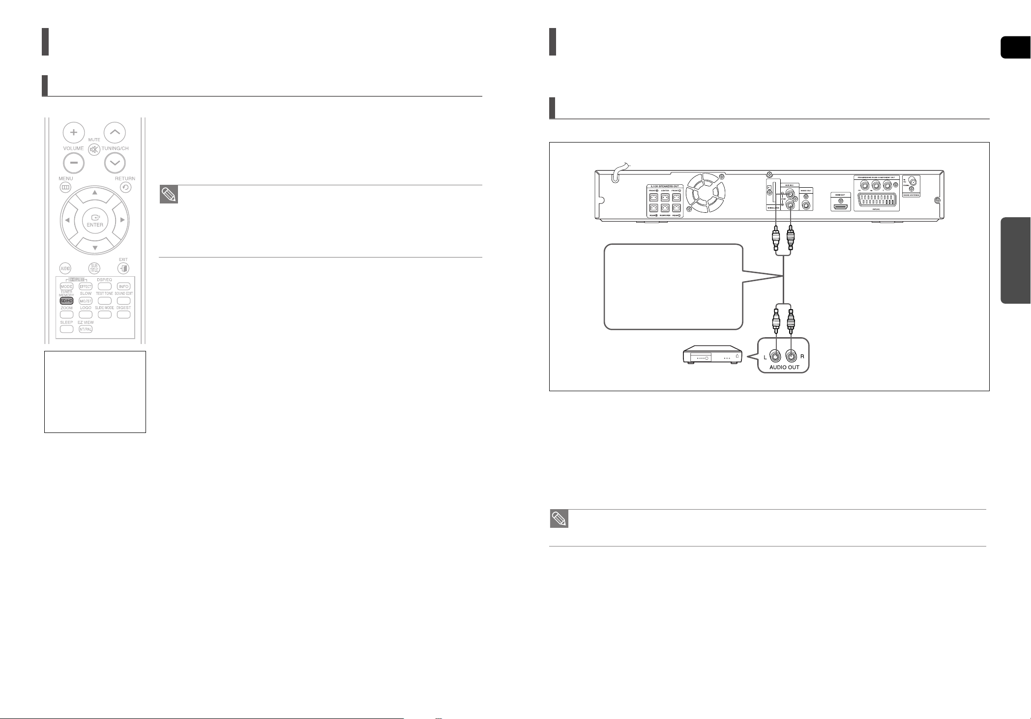
Connecting Audio from External Components
Audio Cable
(not supplied)
If the external analog component
has only one Audio Out, connect
either left or right.
Connecting an External Analog Component
Analog signal components such as a VCR.
1 Connect the AUX IN (Audio) on the Home Theater to the Audio Out of the external analog component.
■
Be sure to match connector colors.
2 Press the AUX button on the remote control to select <AUX> input.
■
You can also use the FUNCTION button on the main unit.
The mode switches as follows : DVD/CD ➝ AUX ➝ USB ➝ FM
• You can connect the Video Output jack of your VCR to the TV, and connect the Audio Output jacks of the VCR to
this product.
HDMI Function
Why use HDMI (High Definition
Multimedia Interface)?
This device transmits a DVD
video signal digitally without
the process of converting to
analog. You will get sharper
digital pictures when using
an HDMI connection.
In Stop mode, press and hold the SD/HD (Standard Definition/High Definition)
button on the remote control.
■
Resolutions available for the HDMI output are 576p(480p), 720p and 1080i.
■
SD(Standard Definition) resolution is 576p(480p) and HD(High Definition) resolution is 720p/1080i.
Resolution Selection
• If the TV does not support the configured resolution, you will not be able to see
the picture properly.
•
When an HDMI cable is connected, composite and component video signals are not
output.
• See your TV owner's manual for more information on how to select the TV's Video
Input source.
This function allows the user to select the screen resolution for HDMI output.
Page 12

GB
23
Before Reading the User's Manual
Icons that will be used in manual
Make sure to check the following terms before reading the user manual.
Icon Term Definition
DVD
CD
MP3
JPEG
DivX
CAUTION
NOTE
DVD
CD
CD
MP3
JPEG
DivX
This involves a function available with DVD or
DVD-R/DVD-RW discs that have been recorded and
finalized in Video Mode.
This involves a function available with a data CD
(CD-R or CD-RW).
This involves a function available with CD-R/-RW discs.
This involves a function available with CD-R/-RW discs.
This involves a function available with MPEG4 discs.
(
DVD R/RW,CD-R or CD-RW)
This involves a case where a function does not
operate or settings may be cancelled.
This involves tips or instructions on the page that help
each function operate.
• In this manual, the instructions marked with "DVD ( )" are applicable to DVD-VIDEO and DVD-R/-
RW discs that have been recorded in Video Mode and then finalized.
Where a particular DVD type is mentioned, it is indicated separately.
• If a DVD-R/-RW disc has not been recorded properly in DVD Video format, it will not be playable.
DVD
OPERATION
22
Connecting the FM Antenna
FM Antenna (supplied)
1 Connect the FM antenna supplied to the FM 75Ω COAXIAL Jack.
2 Slowly move the antenna wire around until you find a location where reception is good, then fasten it
to a wall or other rigid surface.
• This unit does not receive AM broadcasts.
Please observe the following cautions for your safety.
■
Make sure the unit is well-ventilated. If the unit has poor ventilation, the temperature inside the unit
may rise and may damage it.
■
Do not obstruct the cooling fan or ventilation holes. If the cooling fan or ventilation holes are covered
with a newspaper or cloth, heat may build up inside the unit and fire may result.
The cooling fan supplies cool air to the unit to prevent overheating.
Cooling Fan
Page 13

GB
25
OPERATION
Disc Playback
1 Press the OPEN/CLOSE button to open the disc tray.
2 Load a disc.
■
Place a disc gently into the tray with the disc’s label facing up.
3 Close the compartment by pressing the OPEN/CLOSE button again.
■
Playback starts automatically.
• Depending on the content of the disc, the initial screen may appear different.
• Pirated discs will not run in this player because it violates the CSS (Content Scrambling System : a copy protection system)
recommendations.
To stop playback, press the STOP ( ) button during playback.
■
If pressed once, <PRESS PLAY> is displayed and the stop position will be stored in memory.
If the PLAY/PAUSE ( ) button or ENTER button is pressed, playback resumes from the stop position.
(This function works only with DVDs.)
■
If pressed twice, <STOP> is displayed, and if the PLAY/PAUSE ( ) button is pressed, playback starts from
the beginning.
To temporarily pause playback, press the PLAY/PAUSE ()button during playback.
■
To resume playback, press the PLAY/PAUSE ( ) button again.
DVD CD
24
Before Using Your Home Theater
To Operate your Samsung TV and the Home Theater with the HT-THX22/HT-THX25's Remote Control
1 Plug the main unit's power cord into the AC power supply.
■
Before plugging your system into a main socket, you must check the voltage setting.
If the voltage of the socket does not correspond to the setting on the rear of the unit, you
may seriously damage your system.
2 Press the TV button to set the remote to TV mode.
3 Press the POWER button to turn on your Samsung TV
with this remote.
4 Press the TV/VIDEO button to select VIDEO mode on your TV.
5 Press the DVD RECEIVER button to switch to DVD RECEIVER mode to
operate the DVD Home Theater
6 Press the FUNCTION button on the main unit or DVD button
on the remote to enable DVD/CD playback.
Press and hold the NT/PAL button on the remote controller for over 5 seconds
while the power is turned off.
By default, the video format is set to <PAL>.
<NTSC> or <PAL> will appear in the display. At this time, press the NT/PAL button shortly to
select between <NTSC> and <PAL>.
Each country has a different video format standard.
For normal playback, the video format of the disc must be the same as the video format of your TV.
Selecting the Video Format
VIDEO
The DVD Home Theater's remote can be used to control Samsung TVs.
Page 14

GB
OPERATION
27
Images captured with a digital camera or camcorder, or JPEG files on a PC can be stored on a CD and then played
back with this Home Theater.
JPEG File Playback
• The maximum resolutions supported by this product are 5120 x 3480 (or 19.0 MPixel) for
standard JPEG files and 2048 x 1536 (or 3.0 MPixel) for progressive image files.
• If a JPEG file is played when the HDMI output resolution is 720p/1080i, the mode is
automatically converted to 480p/576p mode.
1 Place the JPEG disc on the disc tray.
■
Playback starts automatically. Each image is displayed for 5 seconds and then the next
image is displayed.
2 Press the SLIDE MODE button.
■
Each time the button is pressed, the image makes the transition as follows :
SLIDE SHOW MODE : 1~5 ➝ SLIDE SHOW MODE : RANDOM
➝
SLIDE SHOW MODE : NONE
Press the button to skip to the next slide.
Each time the button is pressed, the slide moves backward or forward.
Slide Mode
1 Press the DIGEST button during playback.
■
JPEG files will be shown in 9 windows.
2 Press the Cursor , , , button to select the desired image and
then press the ENTER button.
■
The selected image is played for 5 seconds before moving to the next image.
To view the previous or next 9 images, press the button.
Digest Function
You can view 9 JPEG images on the TV screen at once.
Press the Cursor , , , button during playback.
Rotate/Flip Function
button: Flip Vertically
button: Flip Horizontally
button: Rotate 90°
Counterclockwise
button: Rotate 90°
Clockwise
Original Image
JPEG
26
MP3/WMA-CD Playback
1 Place the MP3/WMA disc on the disc tray.
■
The MP3/WMA menu screen will appear and playback will start.
■
The appearance of the menu depends on the MP3/WMA disc.
■
WMA-DRM files cannot be played.
2 In Stop mode, use the Cursor , , , button to select the album,
and then press the ENTER button.
■
Use the Cursor ,
button to select the track.
3 To change the album, use the Cursor , , , button to select another
album in Stop mode, and then press the ENTER button.
■
To select another album and track, repeat Steps 2 and 3 above.
4 Press the STOP ( ) button to stop playback.
To play a file icon in the screen,
■
Press the Cursor ,,,button when it is in Stop mode and select a desired icon from the top part of the menu.
Data CDs (CD-R, CD-RW) encoded in MP3/WMA format can be played.
Music File Icon :
To play music files only, select the Icon.
Image File Icon :
To view image files only, select the Icon.
Movie File Icon :
To view movie files only, select the Icon.
All File Icon :
To view movie files only, select the Icon.
• Depending on the recording mode, some MP3/WMA-CDs may not play.
• Table of contents of a MP3-CD varies depending on the MP3/WMAtrack format
recorded on the disc.
MP3
Page 15

GB
OPERATION
29
If the disc has more than one subtitle file, the default subtitle may not match
the movie and you will have to select your subtitle language as follows:
1 In Stop mode, press the Cursor , button, select the desired subtitle ( )
from the TV screen, and then press the ENTER button.
2 When you select the desired DivX file from the TV screen, the movie will be
played normally.
If the Disc has more than One Subtitle File
DivX is a video file format developed by Microsoft and is based on MPEG4 compression technology to provide audio and
video data over the Internet in real-time.
MPEG4 is used for video encoding and MP3 for audio encoding so that the users can watch a movie at near DVD-quality
video and audio.
DivX(Digital internet video eXpress)
1. Supported Formats
This product only supports the following media formats.If both video and audio formats are not supported, the user may
experience problems such as broken images or no sound.
2. Caption Function
• You must have some experience with video extraction and editing in order to use this feature properly.
• To use the caption function, save the caption file (*.smi) in the same file name as that of the DivX media file (*.avi)
within the same folder.
Example. Root Samsung_007CD1.avi
Samsung_007CD1.smi
• Up to 60 alphanumeric characters or 30 East Asian characters (2 byte characters such as Korean and Chinese) for the
file name.
Format MP3 WMA AC3 DTS
Bit Rate 80~384kbps 56~128kbps 128~384kbps 1.5Mbps
Sampling Frequency
44.1khz 44.1/48khz 44.1khz
• DivX files, including audio and video files, created in the DTS format can only support up to 6Mbps.
• Aspect Ratio : Although the default DivX resolution is 640x480 pixels (4:3), this product supports up to 800x600 pixels
(16:9). TV screen resolutions higher than 800 will not be supported.
•
When you play a disc whose sampling frequency is higher than 48khz or 320kbps, you may experience shaking on
the screen during playback.
Supported Audio Formats
Press the SUBTITLE button.
■
Each time you press the button, your selection will toggle between <SUBTITLE (1/N, 2/N ...)>
and <SUBTITLE OFF>.
■
If the disc has only one subtitle file, it will be played automatically.
■
See number 2 (Caption Function) below for more details concerning Subtitle usage with DivX
discs.
Subtitle Display
Format AVI WMV
Supported Versions DivX3.11~DivX5.1, XviD V1/V2/V3/V7
Supported Video Formats
28
The functions on this page apply to DivX disc playback.
DivX Playback
During playback, press the , button.
■
Goes to the next file whenever you press the button, if there are over 2 files in the disc.
■
Goes to the previous file whenever you press the button, if there are over 2 files in the disc.
Skip Forward/Back
During playback, press the Cursor , button.
■
Playback skips 5 minutes forward whenever you press the Cursor button.
■
Playback skips 5 minutes back whenever you press the Cursor button.
5 Minute Skip function
To play back the disc at a faster speed, press the or button during
playback.
■
Each time you press either button, the playback speed will change as follows:
2x ➝ 4x ➝ 8x ➝ 32x ➝ Normal.
Fast Playback
1 Press the ZOOM button.
■
Each time you press the button, your selection will toggle between <ZOOM X2> and
<ZOOM OFF>.
2 Press the Cursor , , , button to move to the area you want to enlarge.
Zoom Function
• ADivX file can be zoomed only in ZOOM X2 mode.
• DivX files have .Avi file extensions, however, not all .Avi files are DivX and may not be
playable in this unit.
DivX
Press the AUDIO button.
■
If there are multiple audio tracks on a disc, you can toggle between them.
■
Each time you press the button, your selection will toggle between <AUDIO (1/N, 2/N ...)> and .
Audio Display
• is displayed when there is one supported language in the disc.
Page 16

GB
OPERATION
31
Press the REMAIN button.
■
For checking the total and remaining time of a title or chapter being played.
Each time the Remain button is pressed
Checking the Remaining Time
Press the , button.
■
Each time the button is pressed during playback, the playback speed changes as follows:
Fast Playback
2X ➝ 4X ➝ 8X ➝ 32X ➝ PLAY
2X ➝ 4X ➝ 8X ➝ 32X ➝ PLAY
Press the SLOW button.
■
Each time the button is pressed during playback, the playback speed changes as follows:
Slow Playback
• No sound is heard during slow playback.
• Reverse slow playback does not work with DivX.
• During fast playback of a CD or MP3-CD, sound is heard only at 2x speed, and not at 4x,
8x, and 32x speeds.
1/2 ➝ 1/4 ➝ 1/8 ➝ 1/2 ➝ 1/4 ➝ 1/8 ➝ PLAY
1/2 ➝ 1/4 ➝ 1/8 ➝ PLAY
DVD CD MP3
DVD CD MP3 DivX
DVD DivX
DVD
DivX
DVD-VIDEO
CD
MP3
TITLE ELAPSED ➝ TITLE REMAIN ➝ CHAPTER ELAPSED ➝ CHAPTER REMAIN
TRACK ELAPSED ➝ TRACK REMAIN ➝ TOTAL ELAPSED ➝ TOTALREMAIN
TRACK REMAIN ➝ TRACK ELAPSED
30
Using the Playback Function
Press the INFO button.
■
Each time the button is pressed, the display changes as follows:
The information
Display disappears
from the screen
The information
Display disappears
from the screen
The information
Display disappears
from the screen
Screen Display
CD display
DVD display
TITLE display
ELAPSED TIME display
SUBTITLE display
TRACK (FILE) display
AUDIO LANGUAGE display
REPEAT PLAYBACK display
ANGLE display
DOLBY DIGITAL display
STEREO (L/R) display
CHAPTER display
Displaying Disc Information
You can view disc playback information on the TV screen.
DVD CD MP3 JPEG DivX
DVD
CD
MP3 JPEG DivX
• Depending on the disc, the disc information display may appear different.
• Depending on the disc, you can also select DTS, DOLBY DIGITAL, or PRO LOGIC.
appears on the TV screen!
If this symbol appears on the TV screen when pressing a button, that operation is not possible with
the disc currently being played.
Page 17

GB
OPERATION
33
CHAPTER : Repeatedly plays the selected chapter.
TITLE : Repeatedly plays the selected title.
RANDOM : Plays tracks in random order.
(Atrack that has already been played may be played again.)
TRACK : Repeatedly plays the selected track.
DIR : Repeatedly plays all tracks in the selected folder.
DISC : Repeatedly plays the entire disc.
OFF : Cancels Repeat Playback.
Repeat Playback Options
Press the REPEAT button.
Each time the button is pressed during playback, the repeat playback mode
changes as follows:
1 Press the INFO button twice.
2 Press the Cursor button to move to REPEAT PLAYBACK ( ) display.
3 Press the Cursor button to select the desired Repeat Playback mode.
To select another album and track, repeat Steps 2 and 3 above.
4 Press the ENTER button.
• For DivX, MP3 and JPEG discs, you cannot select Repeat Play from the information
display screen.
To Select a Repeat Playback Mode in the Disc Information Screen
Repeat playback allows you to repeatedly play a chapter, title, track (song), or directory (MP3 file).
Repeat Playback
DVD CD MP3 JPEG DivX
DVD CD
DVD CD
DVD-VIDEO
CD
MP3 JPEG DivX
REPEAT : CHAPTER ➝ REPEAT : TITLE ➝ REPEAT : OFF
REPEAT : TRACK ➝ REPEAT : DISC ➝ REPEAT : OFF
REPEAT : RANDOM ➝ REPEAT : TRACK ➝ REPEAT : DIR ➝
REPEAT : DISC ➝ REPEAT : OFF
32
Using the Playback Function(Con’t)
Press the , button.
■
Each time the button is pressed during playback, the previous or next chapter, track or
directory (file) will be played.
■
You cannot skip chapters consecutively.
Skipping Scenes/Songs
TITLE 01/05 CHAPTER 002/045 TITLE 01/05 CHAPTER 004/045
DVD MP3
DVD
MP3
Page 18

GB
OPERATION
35
1 Press the INFO button.
2 Press the Cursor button to move to ANGLE ( ) display.
3 Press the Cursor , button or numeric buttons to select the desired angle.
■
Each time the button is pressed, the angle changes as follows:
This function allows you to view the same scene in different angles.
Angle Function
2/3
3/3
1/3
• The Angle function works only with discs on which multiple angles have been recorded.
1 Press the ZOOM button.
2 Press the Cursor , , , button to move to the area you want to enlarge.
3 Press the ENTER button.
■
Each time the button is pressed, the zoom level changes as follows:
ZOOM X 1.5 ➝ ZOOM X 2 ➝ ZOOM X 3 ➝ ZOOM OFF
This function allows you to enlarge a particular area of the displayed image.
Zoom (Screen Enlarge) Function
• When a DivX disc is being played, the screen is enlarged up to twice the normal size.
DVD
DVD DivX
SELECT ZOOM POSITION
34
Using the Playback Function(Con’t)
A-B Repeat Playback
• The A-B Repeat function does not operate with DivX, MP3 or JPEG discs.
• No sound is heard during step motion playback.
1 Press the INFO button twice.
2 Press the Cursor button to move to REPEAT PLAYBACK ( ) display.
3 Press the Cursor , button to select <A-> and then press the ENTER button
at the beginning of the desired segment.
■
When the ENTER button is pressed, the selected position will be stored in memory.
4 Press the ENTER button at the end of the desired segment.
■
The specified segment will be played repeatedly.
To return to normal playback, press the Cursor , button to select
OFF.
You can repeatedly play back a designated section of a DVD.
Press the STEP button.
■
The picture moves forward one frame each time the button is pressed during playback.
A - B
DVD
DVD DivX
Step Function
REPEAT : A-B
Page 19

GB
OPERATION
37
• To operate this function, you can also press the AUDIO or SUBTITLE buttons on
the remote control.
• Depending on the disc, the Subtitle and Audio Language functions may not be available.
1 Press the INFO button twice.
2 Press the Cursor , button or numeric buttons to select the desired audio
language.
■
Depending on the number of languages on a DVD disc, a different audio language
(ENGLISH, SPANISH, FRENCH, etc.) is selected each time the button is pressed.
Audio Language Selection Function
1 Press the INFO button twice.
2 Press the Cursor button to move to SUBTITLE ( ) display.
3 Press the Cursor button or numeric buttons to select the desired subtitle.
Subtitle Language Selection Function
DVD
DVD
36
Using the Playback Function(Con’t)
• This function will not work if the DVD is recorded with multi-camera angle format.
• Black bars may not disappear because some DVD discs have a built-in horizontal to
vertical ratio.
• This feature is not supported for DivX discs.
• During the EZ View operation, some of the left and right sides may be cut slightly.
Press the EZ VIEW button.
Each time the button is pressed, the zoom function will switch between On and Off.
When a movie is played in Widescreen format, black bars at the top and bottom of the TV
screen can be removed by pressing the EZ VIEW button.
EZ VIEW Function
EZ VIEW
EZ VIEW OFF
DVD
SP 2/3
FR 3/3
EN 1/3 EN 01/ 03
SP 02/ 03
FR 03/ 03
OFF / 03
OFF
Page 20

GB
OPERATION
39
Using the Disc Menu
Using the Title Menu
• The disc menu display may be different depending on the disc.
1 In Stop mode, press the MENU button.
2 Press the Cursor , button to move to <Disc Menu> and then press
the ENTER button.
■
When you select Disc Menu and it is not supported by the disc, the <This menu is not
supported> message appears on the screen.
3 Press the Cursor , , , button to select the desired item.
4 Press the ENTER button.
You can use the menus for the audio language, subtitle language, profile, etc.
DVD menu contents differ from disc to disc.
• The Title menu display may be different depending on the disc.
1 In Stop mode, press the MENU button.
2 Press the Cursor , button to move to <Title Menu>.
3 Press the ENTER button.
■
The title menu appears.
Press the EXIT button to exit the setup screen.
Press the EXIT button to exit the setup screen.
For DVDs containing multiple titles, you can view the title of each movie. Depending on the disc, the availability of this feature
may vary.
DVD
DVD
ENTERMOVE EXIT
ENTERMOVE EXIT
38
Using the Playback Function(Con’t)
Moving Directly to a Scene/Song
1 Press the INFO button.
2 Press the Cursor , button or numeric buttons to select the
desired title/track ( ) and then press the ENTER button.
3 Press the Cursor , button to move to the Chapter ( ) display.
4 Press the Cursor , button or numeric buttons to select the
desired chapter and then press the ENTER button.
5 Press the Cursor , button to move to time ( ) display.
6 Press the numeric buttons to select the desired time and then press
the ENTER button.
Press the numeric buttons.
■
The selected file will be played.
■
When playing an MP3 or JPEG disc, you cannot use the Cursor,button to move to a folder.
To move a folder, press the STOP ( ) and then press the Cursor
,
button.
• You can press the button on the remote control to move directly to the desired
title, chapter, or track.
• Depending on the disc, you may not be able to move to the selected title or time.
01/05
001/040 0:00:37 1/1
DVD CD MP3 JPEG
DVD CD
MP3 JPEG
Page 21

GB
OPERATION
41
• CBI (Control/Bulk/Interrupt) is not supported.
• Digital Cameras that use PTP protocol or require additional program installation when connected
to a PC are not supported.
• A device using NTFS file system is not supported. (Only FAT 16/32 (File Allocation Table 16/32) file
system is supported.)
• Some MP3 players, when connected to this product, may not operate depending on the sector size
of their file system.
• The USB host function is not supported if a product that transfers media files by its manufacturer-
specific program is connected.
• Does not operate with Janus enabled MTP (Media Transfer Protocol) devices.
• The USB host function of this product does not support all USB devices. For information on
the supported devices, see page 66.
Supported Formats
File name
File
Bit rate Version Pixel
Sampling
extension Frequency
Still Picture JPG JPG .JPEG ––640x480 –
Music
MP3 .MP3 80~384kbps ––44.1kHz
WMA .WMA 56~128kbps V8 – 44.1kHz
Movie
WMV .WMV 4Mbps V1,V2,V3,V7 720x480 44.1KHz~48KHz
DivX .AVI,.ASF 4Mbps DivX3.11~DivX5.1, XviD 800x600 44.1KHz~48KHz
Compatible Devices
1. USB devices that support USB Mass Storage v1.0. (USB devices that operate as a removable disc
in Windows (2000 or later) without additional driver installation.)
2. MP3 Player: HDD and flash type MP3 players.
3. Digital camera: Cameras that support USB Mass Storage v1.0.
• Cameras that operate as a removable disc in Windows (2000 or later) without additional driver installation.
4. USB HDD and USB Flash Drive: Devices that support USB2.0 or USB1.1.
• You may experience a difference in playback quality when you connect a USB1.1 device.
• For a USB HDD, make sure to connect an auxiliary power cord to the USB HDD for proper operation.
5. USB card Reader: One slot USB card reader and Multi slot USB card reader.
• Depending on the manufacturer. the USB card reader may not be supported.
• If you install multiple memory devices into a multi card reader, you may experience problems.
6. If you use a USB extension cable, the USB device might not be recognized.
40
You can enjoy media files such as pictures, movies and music saved on an MP3 player, USB memory stick or digital camera in
high quality video with 5.1 channel Home Theater sound by connecting the storage device to the USB port of the Home Theater.
Playing Media Files using the USB Host Feature
1 Connect the USB device to the USB port on the front of the unit.
2 Press the FUNCTION button on the DVD Player or the USB button on the
remote control to select the USB mode.
■
<USB> appears on the display screen and then disappears.
■
The USB MENU screen appears on the TV screen and the saved file is played.
3 To stop playback, press the STOP ( ) button.
Safe USB Removal
To prevent damage to the memory stored in the USB device, perform safe removal before
disconnecting the USB cable.
(1) Press the STOP ( ) button twice in a row.
The display will show REMOVE USB.
(2) Remove the USB cable.
During playback, press the button.
■
When there is more than one file and you press the button, the next file is selected.
■
When there is more than one file and you press the button, the previous file is selected.
Skip Forward/Back
To play back the disc at a faster speed, press the button during
playback.
■
Each time you press either button, the playback speed will change as follows:
2x ➝ 4x ➝ 8x ➝ 32x ➝ Normal.
Fast playback
• To listen to your music files with 5.1 channel home theater sound, you must set the Dolby
Pro Logic II mode to Matrix. (See page 53)
Page 22

GB
SETUP
4342
OSD(On-Screen Display) language is set to English by default.
Settings
1 In Stop mode, press the MENU button.
2
Press the Cursor button to move to <Setup> and then press the ENTER button.
3 Select <LANGUAGE> and then press the ENTER button.
4 Press the Cursor , button to select <OSD LANGUAGE> and then press
the ENTER button.
5 Press the Cursor , button to select the desired language and then press
the ENTER button.
Once the setup is complete, the OSD will be English if English has been selected as language.
Press the RETURN button to return to the previous level.
Press the EXIT button to exit the setup screen.
• OSD LANGUAGE : Selecting the OSD Language
• AUDIO : Selecting the Audio Language (recorded on the disc)
• SUBTITLE : Selecting the Subtitle Language (recorded on the disc)
• DISC MENU : Selecting the Disc Menu Language (recorded on the disc)
If the language you selected is not recorded on the disc, menu language will not change even
if you set it to your desired language.
• OTHERS : To select another language, select OTHERS and enter the language code of your country.
(See page 65 for language codes) AUDIO, SUBTITLE and DISC MENU language can be
selected.
Setting the Language
Depending on your TV type (Wide Screen or conventional 4:3), you can select the TV's aspect ratio.
The horizontal to vertical screen size ratio of conventional TVs is 4:3, while that of widescreen and high definition TVs is 16:9. This ratio is
called the aspect ratio. When playing DVDs recorded in different screen sizes, you should adjust the aspect ratio to fit your TV or monitor.
For a standard TV, select either <4:3PS> or <4:3LB> option according to personal preference. Select <WIDE/HDTV> if you have
a widescreen TV.
1 In Stop mode, press the MENU button.
2
Press the Cursor button to move to <Setup> and then press the ENTER button.
3 Press the Cursor button to move to <TV DISPLAY> and then press
the ENTER button.
4 Press the Cursor , button to select the desired item and then press
the ENTER button.
Once the setup is complete, you will be taken to the previous screen.
Press the RETURN button to return to the previous level.
Press the EXIT button to exit the setup screen.
Setting TV Screen Type
Adjusting the TV Aspect Ratio (Screen Size)
MOVE ENTER EXITRETURN
MOVE ENTER EXITRETURN
MOVE ENTER EXITRETURN
MOVE SELECT EXITRETURN
MOVE ENTER EXITRETURN
MOVE SELECT EXITRETURN
4:3PS (4:3 Pan&Scan)
Select this to play a 16:9 picture in the pan & scan mode on a conventional TV .
■
You can see the central portion of the screen only (with the sides of the 16:9 picture cut off).
4:3LB (4:3 Letterbox)
Select this to play a 16:9 picture in the letter box mode on a conventional TV .
■
Black bars will appear at the top and bottom of the screen.
WIDE/HDTV
Select this to view a 16:9 picture in the full-screen mode on your widescreen TV .
■
You can enjoy the widescreen aspect.
• If a DVD is in the 4:3 ratio, you cannot view it in widescreen.
• Since DVD discs are recorded in various image formats, they will look different depending on the software,
the type of TV, and the TV aspect ratio setting.
• When using HDMI, the screen is automatically converted to Wide mode.
Page 23
GB
SETUP
45
Settings (Con’t)
44
Use this to restrict playback of adult or violent DVDs you do not want children to view.
1 In Stop mode, press the MENU button.
2
Press the Cursor button to move to <Setup> and then press the ENTER button.
3
Press the Cursor button to move to <PARENTAL> and then press
the ENTER button.
4 Press the Cursor , button to select the desired rating level and then press
the ENTER button.
If you have selected Level 6, you cannot view DVDs with Level 7 or higher.
The higher the level, the closer the content is to violent or adult material.
5 Enter the password and then press the ENTER button.
The password is set to "7890" by default.
Once the setup is complete, you will be taken to the previous screen.
Press the RETURN button to return to the previous level.
Press the EXIT button to exit the setup screen.
Setting Parental Controls (Rating Level)
You can set the password for the Parental (rating level) setting.
1 In Stop mode, press the MENU button.
2
Press the Cursor button to move to <Setup> and then press the ENTER button.
3 Press the Cursor button to move to <PASSWORD> and then press
the ENTER button.
4 Press the ENTER button.
5 Enter the password and then press the ENTER button.
Enter the old password, a new password, and confirm new password.
The setting is complete.
Setting the Password
• While the player is in No DIsc mode, hold the DVD Players STOP( ) button for longer than 5 seconds. “INITIAL” appears on
the display and all settings will return to the default values.
• Press the POWER button.
Using the RESET function will erase all stored settings.
Do not use this unless necessary.
If you have forgotten the rating level password, do the following
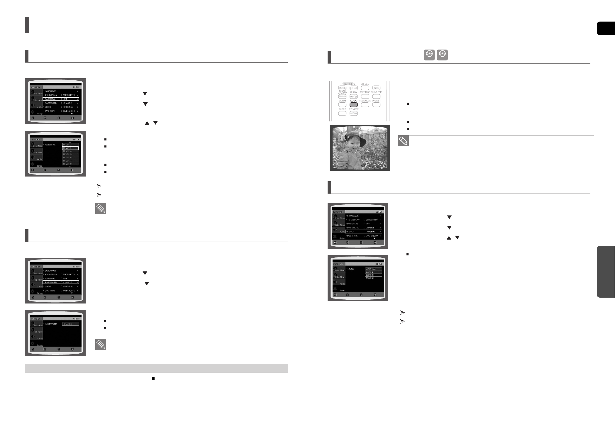
While watching a DVD or JPEG CD, you can set the image you like as background wallpaper.
1
During playback, press the PLAY/PAUSE button when an image you like appears.
2 Press the LOGO button.
<COPY LOGO DATA> will be displayed on the TV screen.
3
The power will turn off and then back on.
The selected wallpaper will be displayed.
You can select up to 3 wallpaper settings.
Setting the Wallpaper
To Select One of the 3 Wallpaper Settings you've made
• This function works only if a DVD disc contains the rating level information.
• The password is set to "7890" by default.
1 In Stop mode, press the MENU button.
2 Press the Cursor button to move to <Setup> and then press the ENTER button.
3 Press the Cursor button to move to <LOGO> and then press the ENTER button.
4
Press the
Cursor , button
select the desired
<USER>
, and then press
the ENTER
button
.
This selects one of the 3 wallpaper screens
5 Press the EXIT button to exit the setup screen.
• ORIGINAL: Select this to set the Samsung Logo image as your wallpaper.
• USER : Select this to set the desired image as your wallpaper.
Press the RETURN button to return to the previous level.
Press the EXIT button to exit the setup screen.
MOVE ENTER EXITRETURN
MOVE SELECT EXITRETURN
MOVE SELECT EXITRETURN
MOVE ENTER EXITRETURN
MOVE ENTER EXITRETURN
MOVE SELECT EXITRETURN
DVD JPEG
COPY LOGO DATA
• This function will not work when the HDMI output is 720p or 1080i.
Page 24

GB
SETUP
4746
• Depending on PRO LOGIC and STEREO settings, the speaker mode may vary
(see page 53).
Signal outputs and frequency responses from the speakers will automatically be adjusted according to your speaker
configuration and whether certain speakers are used or not.
1 In Stop mode, press the MENU button.
2
Press the Cursor button to move to <Audio> and then press the ENTER button.
3
In the
<SPEAKER SETUP>
, press the ENTER button again.
4 Press the Cursor , , , button to move to the desired speaker and then
press the ENTER button.
For C, SL, and SR, each time the button is pressed, the mode switches alternately as follows :
SMALL
➝
NONE.
For L and R, the mode is set to SMALL.
• SMALL : Select this when using the speakers.
• NONE : Select this when no speaker is connected.
Press the RETURN button to return to the previous level.
Press the EXIT button to exit the setup screen.
Setting the Speaker Mode
Settings (Con’t)
If the speakers cannot be placed at equal distances from the listening position, you can adjust the delay time of the audio
signals from the center and rear speakers.
1 In Stop mode, press the MENU button.
2
Press the Cursor button to move to <Audio> and then press the ENTER button.
3 Press the Cursor button to move to <DELAY TIME> and then press
the ENTER button.
4 Press the Cursor , , , button to move to the desired speaker and then
press the ENTER button.
5 Press the Cursor , to set the Delay time.
You can set the delay time for C between 00 and 05mSEC and for SL and SR between 00 and
15mSEC.
Press the RETURN button to return to the previous level.
Press the EXIT button to exit the setup screen.
Setting the Delay Time
When 5.1CH Surround Sound is played, you can enjoy the best sound if the distance between you and each speaker is the same.
Since the sounds arrive at the listening position at different times depending on the placement of speakers, you can adjust this difference by
adding a delay effect to the sound of the Center and Surround Speakers.
Setting CENTER SPEAKER
If the distance of Dc is equal to or longer than the distance of Df in the figure,
set the mode as 0ms. Otherwise, change the setting according to the table.
Setting REAR (SURROUND) SPEAKERS
If the distance of Df is equal to the distance of Ds in the figure, set the mode
as 0ms. Otherwise, change the setting according to the table.
Setting up the Speaker Delay Time
Df: The distance from FRONT SPEAKER
Dc: The distance from CENTER SPEAKER
Ds: The distance from SURROUND SPEAKER
Ideal CENTER SPEAKER
placement
It is desirable to place all speakers within this circle.
Ideal
SURROUND
SPEAKER
placement
Distance between Df and Dc
Delay Time
0.00 m 0.34 m 0.68 m 1.02 m 1.36 m 1.70 m
0 ms 1 ms 2 ms 3 ms 4 ms 5 ms
Distance between Df and Dc
Delay Time
0.00 m 1.02 m 2.04 m 3.06 m 4.08 m 5.10 m
0 ms 3 ms 6 ms 9 ms 12 ms 15 ms
• With (Dolby Pro Logic II), the delay time may be different for each mode.
• With AC-3 and DTS, the delay time can be set between 00 and 15mSEC.
• The Center channel is only adjustable on 5.1 channel discs.
MOVE ENTER EXITRETURN
MOVE CHANGE EXITRETURN
MOVE ENTER EXITRETURN
MOVE CHANGE EXITRETURN
Please use the Registration code to register this player with the DivX (R) video on demand format.
To learn more, go to www.divx.com/vod.
DivX (R) Registration
Page 25

GB
SETUP
4948
Settings (Con’t)
You can adjust the balance and level for each speaker.
1 In Stop mode, press the MENU button.
2
Press the Cursor button to move to <Audio> and then press the ENTER button
.
3 Press the Cursor button to move to <SOUND EDIT> and then press
the ENTER button.
4 Press the Cursor , button to select and adjust the desired item.
Press the Cursor , button to adjust the settings.
Press the RETURN button to return to the previous level.
Press the EXIT button to exit the setup screen.
Setting the Audio
Press the SOUND EDIT button and then press the Cursor , button.
Adjusting Front/Rear Speaker Balance
• You can select between 00, -06, and OFF.
• The volume decreases as you move closer to –6.
Adjusting Center/Rear/Subwoofer Speaker Level
• The volume level can be adjusted in steps from +6dB to –6dB.
• The sound gets louder as you move closer to +6dB and quieter as you get closer to -6dB.
Manually Adjusting the Speaker V olume and Balance with the SOUND EDIT Button.
Use the Test Tone feature to check the speaker connections.
1 In Stop mode, press the MENU button.
2
Press the Cursor button to move to <Audio> and then press the ENTER button.
3 Press the Cursor button to move to <TEST TONE> and then press
the ENTER button.
The test tone will be sent to L ➝ C ➝ R ➝ SR ➝ SL ➝ SW in order.
If the ENTER button is pressed again at this time, the test tone will stop.
Press the RETURN button to return to the previous level.
Press the EXIT button to exit the setup screen.
Setting the Test Tone
Press the TEST TONE button.
■
Test tone will be produced as follows:
When playing a DVD or CD, this will work only in Stop mode.
■
Use this function to check that each speaker is correctly connected and that there is
no problem.
■
When HDMI AUDIO is on (audio is produced through TV speakers),
the TEST TONE function is not available.
To end the test tone, press the TEST TONE button again.
Alternative method: press the TEST TONE button on the remote.
Multi-Channel Pro Logic Mode
Start
L: Front Speaker (L) C: Center Speaker SW: Subwoofer
R: Front Speaker (R) SL: Rear Speaker (L) SR: Rear Speaker (R)
MOVE ENTER EXITRETURN
STOP EXIT
MOVE ENTER EXITRETURN
MOVE CHANGE EXITRETURN
Page 26

GB
SETUP
5150
Settings (Con’t)
Video may look slower than the audio if it is connected to a digital TV. If this occurs, adjust the audio delay time to to match
the video.
1 In Stop mode, press the MENU button.
2
Press the Cursor button to move to <Audio> and then press the ENTER button.
3 Press the Cursor button to move to <AV-SYNC> and then press
the ENTER button.
4 Press the Cursor , button to select the AV-SYNC Delay Time and then
press the ENTER button.
You can set the audio delay time between 0 ms and 300 ms. Set it to the optimal status.
Press the RETURN button to return to the previous level.
Press the EXIT button to exit the setup screen.
Setting the AV SYNC
This feature balances the range between the loudest and quietest sounds. You can use this function to enjoy Dolby Digital
sound when watching movies at low volume at night.
1 In Stop mode, press the MENU button.
2
Press the Cursor button to move to <Audio> and then press the ENTER button.
3
Press the Cursor button to move to <DRC> and then press the ENTER button.
4 Press the Cursor , to adjust the DRC.
When the Cursor button is pressed, the effect is greater, and when the Cursor button is
pressed, the effect is smaller.
Press the RETURN button to return to the previous level.
Press the EXIT button to exit the setup screen.
Setting the DRC (Dynamic Range Compression)
MOVE ENTER RETURN EXIT
CHANGE EXITRETURN
MOVE ENTER EXITRETURN
MOVE SELECT EXITRETURN
The audio signals transmitted over the HDMI Cable can be toggled ON/OFF.
1 In Stop mode, press the MENU button.
2
Press the Cursor button to move to <Audio> and then press the ENTER button.
3 Press the Cursor button to move to <HDMI AUDIO> and then press
the ENTER button.
4 Press the Cursor , button to select <ON> or <OFF> and then press
the ENTER button.
•
ON : Both video and audio signals are transmitted over the HDMI connection cable, and audio
is output through your TV speakers only.
• OFF : Video is transmitted over the HDMI connection cable only, and audio is output through
the home theater speakers only.
Press the RETURN button to return to the previous level.
Press the EXIT button to exit the setup screen.
Setting the HDMI Audio
MOVE ENTER EXITRETURN
MOVE SELECT EXITRETURN
• The default setting of this function is HDMI AUDIO OFF.
• HDMI AUDIO is automatically down-mixed to 2ch for TV speakers.
Page 27

GB
SETUP
5352
Settings (Con’t)
DSP(Digital Signal Processor) : DSP modes have been designed to simulate different acoustic environments.
EQ : You can select ROCK, POP, or CLASSIC to optimize the sound for the genre of music you are playing
Press the DSP/EQ button.
<DSP> appears on the display panel.
Each time the button is pressed, the selection changes as follows:
Sound Field (DSP)/EQ Function
• The DSP/EQ function is only available in STEREO mode.
Press the PL II mode button to show STEREO on the display.
• This feature works with CDs, MP3-CDs, DivX and Dolby Digital discs.
• When playing a DVD disc encoded with two or more channels, multi-channel mode will be
selected automatically and DSP/EQ function does not work.
• POP, JAZZ, ROCK : Depending on the genre of music, you can select POP, JAZZ, and ROCK.
• STUDIO : Provides a sense of presence as if in a studio.
•
CLUB : Simulates the sound of a dance club with a throbbing bass beat.
• HALL : Provides a clear vocal as if listening in a concert hall.
• MOVIE : Provides the feeling of a movie theater.
•
CHURCH : Gives the feel of being in a grand church.
• PASS : Select this for normal listening.
You can select the desired Dolby Pro Logic II audio mode.
Press the PL II MODE button.
Each time the button is pressed, the mode changes as follows.
Dolby Pro Logic II Mode
PRO LOGIC II
• MUSIC: When listening to music, you can experience sound effects as if you are listening to the
actual performance.
• CINEMA : Adds realism to the movie soundtrack.
• PRO LOGIC : You will experience a realistic multi-channel effect, as if using five speakers, while
using just the front left and right speakers.
• MATRIX : You will hear 5.1 channel surround sound.
STEREO : Select this to listen to sound from the front left and right speakers and the subwoofer only.
• When selecting Pro Logic II mode, connect your external device to the AUDIO INPUT jacks
(L and R) on the player. If you connect to only one of the inputs (L or R), you cannot listen to
surround sound.
Page 28

GB
5554
Settings (Con’t)
• When playing a DVD disc encoded with two or more channels, multi-channel mode will be
selected automatically and the (Dolby Pro Logic II) button does not work.
This function works only in Dolby Pro Logic MUSIC mode.
1 Press the PL II MODE button to select <MUSIC> mode.
2 Press the PL II EFFECT button to select <PANORAMA>, then press
the Cursor , button to select the desired effect setting.
You can select either 0 or 1.
This mode extends the front stereo image to include the surround speakers for an exciting
"wraparound" effect with side wall imaging.
3 Press the PL II EFFECT button to select <C-WIDTH>, then press
the Cursor , button to select the desired effect setting.
You can select between 0 and 7.
This sets the width of the center image. The higher the setting, the less sound comes from
the center speaker.
4 Press the PL II EFFECT button to select <DIMENS>, then press the Cursor
, button to select the desired setting
You can select between 0 and 6.
Incrementally adjusts the sound field (DSP) from the front or rear.
Dolby Pro Logic II Effect
Listening to Radio
1 Press the TUNER button to select the FM band.
2 Tune in to the desired station.
Automatic Tuning 1 : When the button is pressed, a preset broadcast station is selected.
Automatic Tuning 2 : Press and hold the button to automatically search for active
broadcasting stations.
Manual Tuning : Briefly press the button to increase or decrease the frequency incrementally.
1 Press the FUNCTION button to select the FM band.
2 Select a broadcast station.
Automatic Tuning 1 : Press the STOP ( ) button to select <PRESET> and then press
the button to select the preset station.
Automatic Tuning 2 : Press the STOP ( ) button to select <MANUAL> and then press and hold
the button to automatically search the band.
Manual Tuning : Press the STOP ( ) button to select <MANUAL> and then briefly press
the button to tune in to a lower or higher frequency.
Press the MO/ST button to listen in Mono/Stereo.
Each time the button is pressed, the sound switches between <STEREO> and <MONO>.
In a poor reception area, select MONO for a clear, interference-free broadcast.
,
,
Remote Control
Main Unit
MISCELLANEOUS
Page 29

GB
MISCELLANEOUS
57
Listening to Radio (Con’t)
56
Presetting Stations
Example : Presetting FM 89.10 in the memory
• This unit does not receive AM broadcasts.
1 Press the TUNER button to select the FM band.
2 Press the button to select <89.10>.
3 Press the TUNER MEMORY button.
<PRGM> flashes in the display.
4 Press the button to select preset number.
You can select between 1 and 15 presets.
5 Press the TUNER MEMORY button again.
Press the TUNER MEMORY button before <PRGM> disappears from the display.
<PRGM> disappears from the display and the station is stored in memory.
6 To preset another station, repeat steps 2 to 5.
To tune in to a preset station, press the button on the remote
control to select a channel.
,
About RDS broadcasting
RDS allows FM stations to send an additional signal along with their regular program signals. For example, the stations
send their station names, as well as information about what type of program they broadcast, such as sports or music, etc.
You can see the RDS signals the station sends on the display.
Press RDS DISPLAY while listening to an FM station.
Each time you press the button, the display change to show you the following information:
About characters shown in the display
When the display shows PS,or RT signals,the following characters are used.
•
The display window cannot differentiate upper case and lower case letters and always uses
upper case letters.
•
The display window cannot show accented letters, “A,” for instance, may stands for accented
“A’s” like “À, Â, Ä, Á, Å and Ã.”
Using the RDS (Radio Data System) to receive FM stations
TO show the RDS signals
• RDS may not operate correctly if the station tuned is not transmitting RDS signal properly or if
the signal strength is weak.
• If searching finishes at once, “PS”, and “RT” will not appear on the display.
When tuned to an FM station which provides the RDS service, the RDS
indicator lights up on the display.
Description on RDS function
• PTY (Program Type) : Displays the type of programme currently being broadcast
• PS NAME (Program Service Name) : Indicates the name of broadcasting station and is composed
of 8 characters.
• RT (Radio Text) : Decodes the text broadcast by a station (if any) and is composed of maximum
64 characters.
• CT (Clock Time) : Decodes the real time clock from the FM frequency.
Some stations may not transmit PTY, RT or CT information therefore this may
not be displayed in all cases.
• TA (Traffic Announcement) : When this symbol flashes it shows that the traffic announcement is in
progress.
• PS (Program Service) : While searching, "PS" appears and then the station names will be
displayed. "NO PS" appears if no signal is sent.
• RT(Radio Text) : while searching, "RT" appears and then text messages the station sends will be
displayed. "NO RT" appears if no signal is sent.
• Frequency : station frequency (non-RDS service)
PS NAME ➝ RT ➝ CT ➝ Frequency
Page 30

58
GB
59
Convenient Functions
You can set the time that the Home Theater will shut itself off.
Press the SLEEP button.
<SLEEP> will be displayed. Each time the button is pressed, the preset time changes as follows :
10 ➝ 20➝ 30➝ 60➝ 90➝ 120➝ 150➝ OFF.
To confirm the sleep timer setting, press the SLEEP button.
The remaining time before the Home Theater will shut itself off is displayed.
Pressing the button again changes the sleep time from what you have set earlier.
To cancel the sleep timer, press the SLEEP button until <OFF> appears on
the display.
Sleep Timer Function
You can adjust the brightness of the display on the main unit so it won't interfere with your movie viewing.
Press the DIMMER button.
Each time the button is pressed, the brightness of front display will be adjusted.
Adjusting Display Brightness
This is useful when answering a doorbell or telephone call.
Press the MUTE button.
<MUTE> appears in the display.
To restore the sound, press the MUTE button again.
Mute Function
MISCELLANEOUS
About RDS broadcasting(Con’t)
One of the advantages of the RDS service is that you can locate a particular kind of program from the preset channels by
specifying the PTY codes.
PTY (Program Type) indication and PTY-SEARCH function
To search for a program using the PTY codes
Before you start, remember...
•
The PTY Search is only applicable to preset stations.
•
To stop searching any time during the process, press PTY SEARCH while searching.
•
There is a time limit in doing the following steps. If the setting is cancelled before you finish, start from step 1 again.
•
When pressing the buttons on the primary remote control, make sure that you have selected the FM
station using the primary remote control.
Display
NEWS
AFFAIRS
INFO
SPORT
EDUCATE
DRAMA
CULTURE
SCIENCE
VARIED
POP M
ROCK M
M.O.R.M
LIGHT M
Program Type
News including an announced opinion and
report
Several matters including a current incident,
documentary, discussion and analysis.
Information including weights and measures,
returns and forecast, matters interesting the customer, medical information, etc.
Sports
Education
Drama-Radio serial, etc.
Culture-National or local culture including the
religious problem, social science, language,
theater, etc.
Natural science and technology
Others-Speech, amusing program (quiz, game),
interview, comedy and satirical play, etc.
Pop music
Rock music
Current contemporary music considered to be
“easy listening.”
Light classical music- Classical music and
instrumental and chorus music
CLASSICS
OTHER M
WEATHER
FINANCE
CHILDREN
SOCIAL A
RELIGION
PHONE IN
TRAVEL
LEISURE
JAZZ
COUNTRY
NATION M
OLDIES
FOLK M
DOCUMENT
Heavy classical music-Orchestra music,
symphony, chamber music and opera
Other music - Jazz, R&B country music
Weather
Finance
Children’s programmes
Social affairs
Religion
Phone in
Travel
Leisure
Jazz Music
Country Music
National Music
Oldies Music
Folk Music
Documentary
Display Program Type
1 Press PTY SEARCH while listening to an FM station.
2 Press the PTY- or PTY+ until the PTY code you want appears on the display.
•
The display gives you the PTY codes described to the right.
3 Press PTY SEARCH again, while the PTY code selected in the previous step
is still on the display.
•
The center unit searches 15 preset FM stations, stops when it finds the
one you have selected, and tunes in that station.
Page 31

GB
6160
Operating a TV with the Remote Control
1 Press the TV button to set the remote to TV mode.
2 Press the POWER button to turn on the TV.
3 While holding down the POWER button, enter the code corresponding
to your brand of TV.
If there is more than one code listed for your TV in the table, enter one at a time to
determine which code works.
Example: For a Samsung TV
While holding down the POWER button, use the number buttons to enter 00, 15, 16, 17
and 40.
4 If the TV turns off, the setting is complete.
You can use the TV POWER, VOLUME, CHANNEL, and Numeric buttons (0~9).
When Operating a TV with the Remote Control
• The Remote control may not work on some brands of TVs. Also, some operations may
not be possible depending on your brand of TV.
• If you do not set the remote control with the code for your brand of TV, the remote control
will work on a Samsung TV by default.
MISCELLANEOUS
TV Brand Code List
1
2
3
4
5
6
7
8
9
10
11
12
13
14
15
16
17
18
19
20
21
22
23
24
25
26
27
28
29
30
31
32
33
34
35
36
37
38
39
40
41
42
43
Admiral (M.Wards)
A Mark
Anam
AOC
Bell & Howell (M.Wards)
Brocsonic
Candle
Cetronic
Citizen
Cinema
Classic
Concerto
Contec
Coronado
Craig
Croslex
Crown
Curtis Mates
CXC
Daewoo
Daytron
Dynasty
Emerson
Fisher
Funai
Futuretech
General Electric (GE)
Hall Mark
Hitachi
Inkel
JC Penny
JVC
KTV
KEC
KMC
LG (Goldstar)
Luxman
LXI (Sears)
Magnavox
Marantz
Matsui
MGA
Mitsubishi/MGA
No.
Brand
Code
56, 57, 58
01, 15
01, 02, 03, 04, 05, 06, 07, 08, 09, 10, 11, 12,
13, 14
01, 18, 40, 48
57, 58, 81
59, 60
18
03
03, 18, 25
97
03
18
46
15
03, 05, 61, 82, 83, 84
62
03
59, 61, 63
03
02, 03, 04, 15, 16, 17, 18, 19, 20, 21, 22, 23, 24,
25, 26, 27, 28, 29, 30, 32, 34, 35, 36, 48, 59, 90
40
03
03, 15, 40, 46, 59, 61, 64, 82, 83, 84, 85
19, 65
03
03
06, 40, 56, 59, 66, 67, 68
40
15, 18, 50, 59, 69
45
56, 59, 67, 86
70
59, 61, 87, 88
03, 15, 40
15
01, 15, 16, 17, 37, 38, 39, 40, 41, 42, 43, 44
18
19, 54, 56, 59, 60, 62, 63, 65, 71
15, 17, 18, 48, 54, 59, 60, 62, 72, 89
40, 54
54
18, 40
18, 40, 59, 60, 75
44
45
46
47
48
49
50
51
52
53
54
55
56
57
58
59
60
61
62
63
64
65
66
67
68
69
70
71
72
73
74
75
76
77
78
79
80
81
82
83
84
85
86
MTC
NEC
Nikei
Onking
Onwa
Panasonic
Penney
Philco
Philips
Pioneer
Portland
Proton
Quasar
Radio Shack
RCA/Proscan
Realistic
Sampo
Samsung
Sanyo
Scott
Sears
Sharp
Signature 2000 (M.Wards)
Sony
Soundesign
Spectricon
SSS
Sylvania
Symphonic
Tatung
Techwood
Teknika
TMK
Toshiba
Vidtech
Videch
Wards
Yamaha
York
Yupiteru
Zenith
Zonda
Dongyang
No.
Brand
Code
18
18, 19, 20, 40, 59, 60
03
03
03
06, 07, 08, 09, 54, 66, 67, 73, 74
18
03, 15, 17, 18, 48, 54, 59, 62, 69, 90
15, 17, 18, 40, 48, 54, 62, 72
63, 66, 80, 91
15, 18, 59
40
06, 66, 67
17, 48, 56, 60, 61, 75
18, 59, 67, 76, 77, 78, 92, 93, 94
03, 19
40
00, 15, 16, 17, 40, 43, 46, 47, 48, 49, 59, 60,
98
19, 61, 65
03, 40, 60, 61
15, 18, 19
15, 57, 64
57, 58
50, 51, 52, 53, 55
03, 40
01
18
18, 40, 48, 54, 59, 60, 62
61, 95, 96
06
18
03, 15, 18, 25
18, 40
19, 57, 63, 71
18
59, 60, 69
15, 17, 18, 40, 48, 54, 60, 64
18
40
03
58, 79
01
03, 54
Page 32

GB
6362
•
Is the TV power on?
•
Are the video cables connected properly?
•
Is the disc dirty or damaged?
•
A poorly manufactured disc may not be playable.
• Disc is rotating but no
picture is produced.
• Picture quality is poor and
picture is shaking.
•
Audio language and subtitles will not work if the disc does not
contain them.
Audio language and subtitles
do not work.
•
Are you using a disc that does not contain menus?
Menu screen does not appear
even when the menu function is
selected.
•
While “NO DISC” message appears on the display of main unit, hold
the main unit's STOP ( ) button for longer than 5 seconds. “INITIAL”
appears on the display and all settings will return to the default values.
•
Press the POWER button.
Using the RESET function will erase all stored settings.
Do not use this unless necessary.
•
Turn off the power and hold the
STOP ()
button on the main unit
for longer than 5 seconds.
Using the RESET function will erase all stored settings.
Do not use this unless necessary.
The password for rating level
has been forgotten.
• The main unit is not working.
(Example: The power goes out
or strange noise is heard.)
• The DVD player is not working
normally.
•
Is the antenna connected properly?
•
If the antenna's input signal is weak, install an external FM
antenna in an area with good reception.
Can't receive radio broadcast.
Symptom Check/Remedy
•
You can play 16:9 DVDs in 16:9 WIDE mode, 4:3 LETTER BOX
mode, or 4:3 PAN SCAN mode, but 4:3 DVDs can be seen in 4:3
ratio only. Refer to the DVD disc jacket and then select the
appropriate function.
Aspect ratio cannot be changed.
MISCELLANEOUS
Refer to the chart below when this unit does not function properly. If the problem you are experiencing is not listed below
or if the instruction below does not help, turn off the unit, disconnect the power cord, and contact the nearest authorized
dealer or Samsung Electronics Service Center.
Troubleshooting
•
Is the power cord plugged securely into the outlet?
•
Turn off the power and then turn it back on.
•
Check the region number of the DVD.
DVD discs purchased from abroad may not be playable.
•
CD-ROMs and DVD-ROMs cannot be played on this DVD
player.
•
Make sure that the rating level is correct.
•
Are you using a deformed disc or a disc with scratches on
the surface?
•
Wipe the disc clean.
Disc tray does not open.
Playback does not start.
Playback does not start
immediately when the
Play/Pause button is pressed.
•
No sound is heard during fast playback, slow playback, and step
motion playback.
•
Are the speakers connected properly? Is the speaker setup
correctly customized?
•
Is the disc severely damaged?
Sound is not produced.
Sound can be heard only from a
few speakers and not all six.
•
When listening to a CD or radio, sound is output to the front
speakers (L/R) only. Select "PRO LOGIC II" by pressing
PL II
(Dolby Pro Logic II) on the remote control to use all six speakers.
•
Make sure that the DVD disc is 5.1-CH compatible.
•
If you set C, SL, and SR to NONE in the speaker mode in the
audio setup of the setup screen, no sound is heard from the
center speaker and the front left and right speakers. Set C, SL,
and SR to SMALL.
•
Is there "Dolby Digital 5.1 CH" mark on the disc? Dolby Digital
5.1 CH Surround Sound is produced only if the disc is recorded
with 5.1 channel sound.
•
Is the audio language correctly set to DOLBY DIGITAL 5.1-CH in
the information display?
Dolby Digital 5.1 CH Surround
Sound is not produced.
Symptom Check/Remedy
•
Is the remote control being operated within its operation range of
angle and distance?
•
Are the batteries exhausted?
•
Have you selected the mode(TV/DVD) functions of the remote
control (TV or DVD) correctly?
The remote control does not
work.
Page 33

GB
6564
Small scratches on the disc may reduce sound and picture quality or cause skipping.
Be especially careful not to scratch discs when handling them.
Cautions on Handling and Storing Discs
Do not touch the playback side of the disc.
Hold the disc by the edges so that fingerprints will not get on
the surface.
Do not stick paper or tape on the disc.
Do not keep in
direct sunlight
Keep in a cool
ventilated area
Keep in a clean
Protection jacket.
Store vertically.
When you get fingerprints or dirt on the disc, clean it with a mild
detergent diluted in water and wipe with a soft cloth.
•
When cleaning, wipe gently from the inside to the outside of the
disc.
• Condensation may form if warm air comes into contact with cold parts inside
the player. When condensation forms inside the player, the player may not
operate correctly. If this occurs, remove the disc and let the player stand for
1 or 2 hours with the power on.
• Do not allow the discs to become contaminated with dirt.
• Do not load cracked or scratched discs.
Handling discs
Disc Storage
Handling and Storing Discs
MISCELLANEOUS
Enter the appropriate code number for the initial settings “Disc Audio”, “Disc Subtitle” and/or “Disc Menu” (See page 42).
Language Code List
Code Language Code Language Code Language Code Language
1027 Afar 1181 Frisian 1334 Latvian, Lettish 1506 Slovenian
1028 Abkhazian 1183 Irish 1345 Malagasy 1507 Samoan
1032 Afrikaans 1186 Scots Gaelic 1347 Maori 1508 Shona
1039 Amharic 1194 Galician 1349 Macedonian 1509 Somali
1044 Arabic 1196 Guarani 1350 Malayalam 1511 Albanian
1045 Assamese 1203 Gujarati 1352 Mongolian 1512 Serbian
1051 Aymara 1209 Hausa 1353 Moldavian 1513 Siswati
1052 Azerbaijani 1217 Hindi 1356 Marathi 1514 Sesotho
1053 Bashkir 1226 Croatian 1357 Malay 1515 Sundanese
1057 Byelorussian 1229 Hungarian 1358 Maltese 1516 Swedish
1059 Bulgarian 1233 Armenian 1363 Burmese 1517 Swahili
1060 Bihari 1235 Interlingua 1365 Nauru 1521 Tamil
1069 Bislama 1239 Interlingue 1369 Nepali 1525 Tegulu
1066 Bengali; Bangla 1245 Inupiak 1376 Dutch 1527 Tajik
1067 Tibetan 1248 Indonesian 1379 Norwegian 1528 Thai
1070 Breton 1253 Icelandic 1393 Occitan 1529 Tigrinya
1079 Catalan 1254 Italian 1403 (Afan) Oromo 1531 Turkmen
1093 Corsican 1257 Hebrew 1408 Oriya 1532 Tagalog
1097 Czech 1261 Japanese 1417 Punjabi 1534 Setswana
1103 Welsh 1269 Yiddish 1428 Polish 1535 Tonga
1105 Danish 1283 Javanese 1435 Pashto, Pushto 1538 Turkish
1109 German 1287 Georgian 1436 Portuguese 1539 Tsonga
1130 Bhutani 1297 Kazakh 1463 Quechua 1540 Tatar
1142 Greek 1298 Greenlandic 1481 Rhaeto-Romance 1543 Twi
1144 English 1299 Cambodian 1482 Kirundi 1557 Ukrainian
1145 Esperanto 1300 Kannada 1483 Romanian 1564 Urdu
1149 Spanish 1301 Korean 1489 Russian 1572 Uzbek
1150 Estonian 1305 Kashmiri 1491 Kinyarwanda 1581 Vietnamese
1151 Basque 1307 Kurdish 1495 Sanskrit 1587 Volapuk
1157 Persian 1311 Kirghiz 1498 Sindhi 1613 Wolof
1165 Finnish 1313 Latin 1501 Sangro 1632 Xhosa
1166 Fiji 1326 Lingala 1502 Serbo-Croatian 1665 Yoruba
1171 Faeroese 1327 Laothian 1503 Singhalese 1684 Chinese
1174 French 1332 Lithuanian 1505 Slovak 1697 Zulu
Page 34

GB
USB Host Feature Supported Products
6766
Finepix-A340 Fuji Digital Camera
Finepix-F810 Fuji Digital Camera
Finepix-F610 Fuji Digital Camera
Finepix-f450 Fuji Digital Camera
Finepix S7000 Fuji Digital Camera
Finepix A310 Fuji Digital Camera
KD-310Z Konica Digital Camera
Finecam SL300R Kyocera Digital Camera
Finecam SL400R Kyocera Digital Camera
Finecam S5R Kyocera Digital Camera
Finecam Xt Kyocera Digital Camera
Dimage-Z1 Minolta Digital Camera
Dimage Z1 Minolta Digital Camera
Dimage X21 Minolta Digital Camera
Coolpix4200 Nikon Digital Camera
Coolpix4300 Nikon Digital Camera
Coolpix 2200 Nikon Digital Camera
Coolpix 3500 Nikon Digital Camera
Coolpix 3700 Nikon Digital Camera
Coolpix 4100 Nikon Digital Camera
Coolpix 5200 Nikon Digital Camera
Stylus 410 digital Olympus Digital Camera
300-digital Olympus Digital Camera
U300 Olympus Digital Camera
X-350 Olympus Digital Camera
C-760 Olympus Digital Camera
C-5060 Olympus Digital Camera
X1 Olympus Digital Camera
U-mini Olympus Digital Camera
Lumix-FZ20 Panasonic Digital Camera
DMC-FX7GD Panasonic Digital Camera
Lumix LC33 Panasonic Digital Camera
LUMIX DMC-F1 Panasonic Digital Camera
Optio-S40 Pentax Digital Camera
Optio-S50 Pentax Digital Camera
Optio 33LF Pentax Digital Camera
Optio MX Pentax Digital Camera
Digimax-420 Samsung Digital Camera
Digimax-400 Samsung Digital Camera
Sora PDR-T30 Toshiba Digital Camera
Coolpix 5900 Nikon Digital Camera
Coolpix S1 Nikon Digital Camera
Coolpix 7600 Nikon Digital Camera
DMC-FX7 Panasonic Digital Camera
Dimage Xt Minolta Digital Camera
AZ-1 Olympus Digital Camera
Product Company Type
Digital Camera
Cruzer Micro Sandisk USB 2.0 USB Flash Drive 128M
Cruzer Mini Sandisk USB 2.0 128M
Cruzer Mini Sandisk USB 2.0 256M
SONY Micro Vault Sony USB 2.0 64MB
FLEX DRIVE Serotech USB 2.0 32MB
AnyDrive A.Ltech USB 2.0 128MB
XTICK LG USB 2.0 128M
Micro Mini Iomega USB 2.0 128M
iFlash Imation USB 2.0 64M
LG XTICK(M) USB 2.0 64M
RiDATA EZDrive USB 2.0 64M
Product Company Type
USB Flash Disc
Creative MuVo NX128M Creative 128 MB MP3 Player
Iriver H320 Iriver 20G HDD MP3 Player
YH-920 Samsung 20G HDD MP3 Player
YP-T7 Samsung MP3 Player
YP-MT6 Samsung MP3 Player
YP-T6 Samsung MP3 Player
YP-53 Samsung MP3 Player
YP-ST5 Samsung MP3 Player
YP-T5 Samsung MP3 Player
YP-60 Samsung MP3 Player
YP-780 Samsung MP3 Player
YP-35 Samsung MP3 Player
YP-55 Samsung MP3 Player
iAUDIO U2 Cowon MP3 Player
iAUDIO G3 Cowon MP3 Player
iAudio M3 Cowon HDD MP3 Player
SI-M500L Sharp 256MB MP3 Player
H10 Iriver MP3 Player
YP-T5 VB Samsung MP3 Player
YP-53 Samsung 256MB MP3 Player
Product Company Type
MP3 Player
Specifications
MISCELLANEOUS
Power Consumption
Weight
Dimensions (W x H x D)
Operating Temperature Range
Operating Humidity Range
Usable Sensitivity
S/N Ratio
Distortion
Composite Video
Scart Jack
Component Video
HDMI
Front speaker output
Center speaker output
Rear speaker output
Subwoofer speaker output
Frequency range
S/N Ratio
Channel separation
Input sensitivity
GENERAL
FM
TUNER
VIDEO
OUTPUT
AMPLIFIER
80W
3.3Kg
430 x 65 x 351.5 mm
+5°C~+35°C
10% ~ 75%
10dB
60dB
0.5%
1.0Vp-p(75Ω load)
Compositive Video : 1.0Vp-p(75Ω load)
RGB Signal : 0.714Vp-p(75Ω load)
Y:1.0Vp-p(75Ω load)
Pr:0.70Vp-p(75Ω load)
Pb:0.70Vp-p(75Ω load)
Impedance: 85~115Ω
100W x 2(3Ω)
100W(3Ω)
100W x 2(3Ω)
100W(3Ω)
20Hz~20KHz
75dB
60dB
(AUX)400mV
Page 35

68
Specifications
Contact SAMSUNG WORLD WIDE
If you have any questions or comments relating to Samsung products, please contact the SAMSUNG customer care centre.
Region Country Customer Care Center Web Site
Speaker system
Impedance
Frequency range
Output sound pressure level
Rated input
Maximum input
Dimensions (W x H x D)
Weights
SPEAKER
Subwoofer speaker
3Ω
45Hz ~160Hz
86dB/W/M
100W
200W
175 x 320 x 390 mm
4.6kg
Front
Rear
Center
90 x 1045 x 95 mm
(Stand : 270)
90 x 168 x 95 mm
250 x 90 x 95 mm
3.25kg/0.5kg
0.7kg
Front/Rear
Center
Front/Center/Rear speaker
3Ω x 5
140Hz ~20kHz
86dB/W/M
100W
200W
5.1ch speaker system
HT-THX22
Speaker system
Impedance
Frequency range
Output sound pressure level
Rated input
Maximum input
Dimensions (W x H x D)
Weights
SPEAKER
Subwoofer speaker
3Ω
45Hz ~160Hz
86dB/W/M
100W
200W
175 x 320 x 390 mm
4.6kg
Front/Rear
Center
90 x 1045 x 95 mm
(Stand : 270)
250 x 90 x 95 mm
3.25kg/3.0kg
0.7kg
Front/Rear
Center
Front/Center/Rear speaker
3Ω x 5
140Hz ~20kHz
86dB/W/M
100W
200W
5.1ch speaker system
HT-THX25
 Loading...