

Page 1
Instruction Manual
Page 2
Safety Warnings
Note to CATV system installer :
LASSE 1 LASER PRODUKT
OKAN 1 LASER LAITE
LASS 1 LASER APPARAT
LASS 1 LASER PRODUCT I I
RODUCTO LASER CLASE 1
This reminder is provided to call the CATV system
installer's attention to Section 820_40 of the NEC
which provides guidelines for proper grounding and,
in particular, specifies that the cable ground shall be
connected to the grounding system of the building,
as close to the point of cable entry as practical
CLASS 1 LASER PRODUCT
CAUTION:
TO REDUCE THE RISK OF ELECTRIC
SHOCK, DO NOT REMOVE REAR COVER.
NO USER SERVICEABLE PARTS INSIDE.
REFER SERVICING TO QUALIFIED
SERVICE PERSONNEL.
//_ This symbol indicates that dangerous voltage which can cause electricshock is present insidethis unit.
This symbol alerts you to important operating and maintenance instructions accompanying
the unit.
This Compact Disc player is classified as a CLASS 1
LASER product.
Use of controls, adjustments or performance of
procedures other than those specified herein may result
in hazardous radiation exposure.
CAUTION-INVISIBLE LASER RADIATIONWHEN OPEN
AND INTERLOCK8 DEFEATED,AVOID
EXPOSURE TO BEAM.
WARNING: To reduce the risk of fire or electric shock, do not expose this appliance to rainor moisture.
CAUTION: TO PREVENT ELECTRIC SHOCK, MATCH WIDE BLADE OF PLUGTO WIDE SLOT, FULLY
INSERT.
Page 3
Precautions
"_iiii iii_ii iiiiiiiiiiiiiiiiiiiiiiiiiiiiiiiiiiiiii _
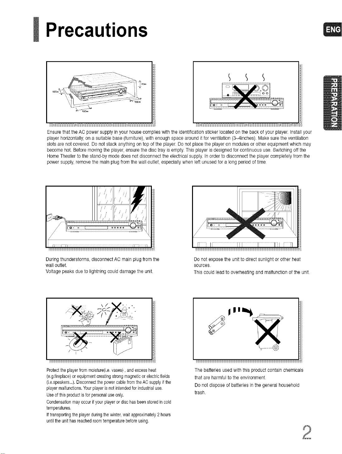
Ensure that the AO power supply in your house complies with the identification sticker located on the back of your player. Install your
player horizontally, on a suitable base (furniture), with enough space around itfor ventilation (3N4inches). Make sure the ventilation
slots are not covered. Do not stack anything on top of the player. Do not place the player on modules or other equipment which may
become hot. Before moving the player, ensure the disc tray is empty. This player is designed for continuous use. Switching off the
Home Theater to the stand-by mode does not disconnect the electrical supply. In order to disconnect the player completely from the
power supply, remove the mainplug from the wal! outlet, especially when left unused for a long period of time
/ . /' / /'
/ / / /
J
During thunderstorms, disconnect AC main plug from the
wal! outlet.
Voltage peaks due to lightning could damage the unit.
\ / V',' •
Protecttheplayerfrommoisture(i.e,vases),andexcessheat
(e,g.fireplace)orequipmentcreatingstrongmagneticor electricfields
(i.e.speakers...).DisconnectthepowercablefromtheAOsupplyif the
playermalfunctions.Yourplayerisnotintendedfor industrialuse.
Useof this productis forpersonaluseonly.
Oondensationmayoccurifyour playeror dischas beenstoredincold
temperatures.
Iftransportingthe playerduringthewinter,waitapproximately2 hours
untiltheunithasreachedroomtemperaturebefore using.
Do not expose the unit to direct sunlight or other heat
sources.
This could lead to overheating and malfunction of the unit.
The batteries used with this product contain chemicals
that are harmful to the environment.
Do not dispose of batteries inthe general household
trash.
Page 4
SafetyInstructions
READ INSTRUCTIONS
All the safety and operating instructions should be
read before the appliance is operated.
RETAIN INSTRUCTIONS
The safety and operating instructions should be
retained for future reference.
HEED WARNINGS
All warnings on the appliance and in the operating
instructions should be adhered to.
FOLLOW INSTRUCTIONS
All operating and use instructions should be
followed.
WATER AND MOISTURE
Do not use this video product near water-
for example, near a bathtub, wash bowl,
kitchen sink, or laundry tub, in a wet basement,
or near a swimming poo!, and the like.
OVERLOADING
De net overload wall outlets and extension cords as
this can result in the risk of fire
or electric shock.
VENTILATION
Slots and openings in the cabinet are provided
for ventilation and to ensure reliable operation of the
video product and to protect it from overheating
these openings must net be blocked or covered.
The openings should never be blocked
by placing the video product on a bed, sofa, rug, or
other similar surface. This video product
should never be placed near or over a radiator or
heat register.
This video product should not be placed
in a built-in installation such as a bookcase
or rack unless proper ventilation is provided
or the manufacturer's instructions have been fol-
lowed.
POWER CORD PROTECTION
Power-supply cords should be routed so that
they are net likely to be walked on or pinched
by items placed upon or against them paying
particular attention to cords at plugs,
convenience receptacles, and the point where
they exit from the appliance.
CLEANING
Unplug this video product from the wall outlet
before cleaning. Do net use liquid cleaners
or aerosol cleaners. Usea damp cloth for cleaning.
LIGHTNING
For added protection of this video product
receiver during a lightning storm, or when
it is left unattended and unused for long
periods of time, unplug it from the wall outlet
and disconnect the antenna or cable system.
This will prevent damage to the video product
due to lightning and power-line surges.
OBJECT AND LIQUID ENTRY
Never push objects of any kind into this
product through openings as they may touch
dangerous voltage points or short-out parts
that could result in a fire or electric shock.
Never spill liquid of any kind on the video
product.
ACCESSORIES
Do not place this video product on an unstable cart,
stand, tripod, bracket, or table.
The video product may fall, causing serious injury to
a child or adult, and serious damage
to the appliance.
Use only with a cart, stand, tripod, bracket,
or table recommended by the manufacturer,
or sold with the video product. Any mounting
of the appliance should follow the manufacturer's
instructions and should use a mounting accessory
recommended by the manufacturer.
CART
An appliance and cart combination should be moved
with care. Quick stops, excessive force, and uneven
surfaces may cause the appliance and cart combina-
tion to overturn.
POWER SOURCES
This video product should be operated only from the
type of power source indicated
on the marking label. If you are not sure
of the type of supply to your home, consult your
appliance dealer or local power company.
For video products intended to be operated from bat-
tery power, or other sources, refer
to the operating instructions.
Page 5
POWERLINES
Anoutsideantennasystemshouldnotbelocatedin
thevicinityofoverheadpowerlinesorotherelectric
lightorpowercircuits,
orwhereitcanfallintosuchpowerlines
orcircuits.Wheninstallinganoutsideantennasys-
tem,extreme care should be taken to keep from
touching such power lines or circuits as contact with
them might be fatal.
POLARIZATION
This video product is equipped with a polarized
alternating current line plug (a plug having one
blade wider than the other.) This plug will fit into the
power outlet only one way.
This is a safety feature. If you are unable
to insert the plug fully into the outlet, try reversing the
plug. tf the plug should still fail to fit, contact your
electrician to replace your obsolete outlet. Do not
defeat the safety purpose of the polarized plug.
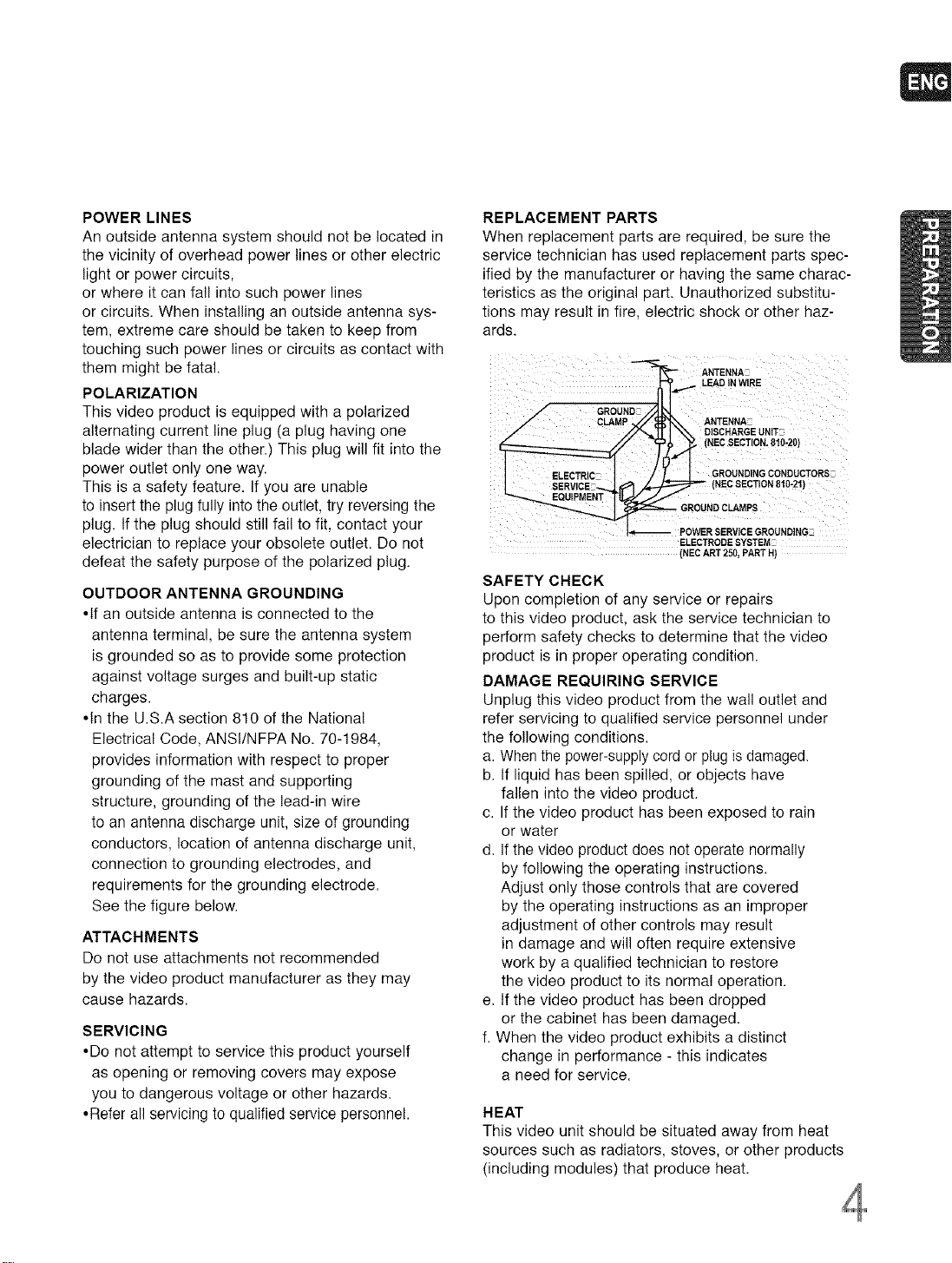
OUTDOOR ANTENNA GROUNDING
•If an outside antenna is connected to the
antenna terminal, be sure the antenna system
is grounded so as to provide some protection
against voltage surges and built-up static
charges.
•In the U.S.A section 810 of the National
Electrical Code, ANSt/NFPA No. 70-1984,
provides information with respect to proper
grounding of the mast and supporting
structure, grounding of the lead-in wire
to an antenna discharge unit, size of grounding
conductors, location of antenna discharge unit,
connection to grounding electrodes, and
requirements for the grounding electrode.
See the figure below.
ATTACHMENTS
Do not use attachments not recommended
by the video product manufacturer as they may
cause hazards.
SERVICING
•Do not attempt to service this product yourself
as opening or removing covers may expose
you to dangerous voltage or other hazards.
•Refer all servicing to qualified service personnel.
REPLACEMENT PARTS
When replacement parts are required, be sure the
service technician has used replacement parts spec-
ified by the manufacturer or having the same charac-
teristics as the original part. Unauthorized substitu-
tions may result in fire, electric shock or other haz-
ards.
ANTENNA
_,_ LEAD IN WIRE
GROUND
CLAMP ANTENNA-
_ GROUNDCLAMPS
DISCHARGE UNIT-
(NECSECTION,810-20)
(NECSECTION810-21)
POWER SERV]CEGROUNDING_
ELECTRODE SYSTEM-
(NECART 250, PART H)
SAFETY CHECK
Upon completion of any service or repairs
to this video product, ask the service technician to
perform safety checks to determine that the video
product is in proper operating condition.
DAMAGE REQUIRING SERVICE
Unplug this video product from the wall outlet and
refer servicing to qualified service personnel under
the following conditions.
a. When the power-supply cord or plug is damaged.
b. If liquid has been spilled, or objects have
fallen into the video product.
c. If the video product has been exposed to rain
or water
d. If the video product does not operate normally
by following the operating instructions.
Adjust only those controls that are covered
by the operating instructions as an improper
adjustment of other controls may result
in damage and will often require extensive
work by a qualified technician to restore
the video product to its normal operation.
e. tf the video product has been dropped
or the cabinet has been damaged.
f. When the video product exhibits a distinct
change in performance - this indicates
a need for service.
HEAT
This video unit should be situated away from heat
sources such as radiators, stoves, or other products
(including modules) that produce heat.
Page 6
Features
_ii_;Multi-Disc Playback & FM Tuner
The HT-Q70 combinesthe convenienceof multi-disc playback capability, including
DVD-AUDIO, DVD-VIDEO,CD, MP3-CD. WMA-CD. DivX.CD-R/RW. and DVD-R/RW.with a
sophisticated FMtuner, all in a single player.
_II_USB Host Play
Youcan enjoy mediafiles such as pictures, movies and tunes saved inan MP3 player digital _ ra
or USB memory by connecting the storage device to the USB port of the home theater.
©Dolby Pro Logic II
Dolby ProLogic II is a newform
that improves uponexisting
signal decoding technology
©DTS (Digital Theater
and set it as your background wallpaper.
HDMI transmits DVD video and audio signals simultaneously, and provides a clearer picture.
@AV SYNC Function
Video may lag behindthe audio ifthe unit is connected to a digital TV.
Tocompensate for this, you can adjustthe audio delay timeto sync up withthe video.
,:_ii;_Optional XM radio
Samsung's XM Ready HomeTheater Systems give youthe opportunity to enjoyAmerica's
leading satellite radio service in CD-quality sound.
_;_Optional Wireless receiver amplifier
Samsung's optional rear-channel wireless module does awaywith cables running between
your DVDreceiver and rear-channelspeakers. Instead,the rear speakers connect to a com-
pact wireless module thatcommunicates with your DVD receiver.
Page 7
Contents
PREPARATION
SafetyWarnings........:
Sa!ety InStrUCtions..i.
Feat es... ;..i!i ..,.L..i.
Noteson Discs .i..1...
Description..:,,:::..,L
} C()NNE !101 ..............................ii .....
* Co,,r_ecti_g 7_p;[ i .16 Range rb_ _,:/.
fio_i_n<J;;:! .... E L.._.t.,_L.L..LI ......6_
:: MP }._A _ :: : __::,/, _ tliteRadio .......................................68
_R_ t._;: i_. : .i.i. :_. ,!.i_i,._, ! riteRadio.............................................72
_ _ ii,,};:../!L:;i.:'.: i ons.........................................................7_
_at P!a _ _..... .>_,. ....... ..... ththe RemoteControl...........................75
;i_ "B_ i__b_ ,i... :ii.i.i......i ........... _ BeforeCalling for Se_'ice:..................................................77
';8te __unction................................................... 37 cautions on Handlingand Storing Discs............................79
An_ _eFunction......................................................................37
Zoom(Screen Enlarge) Function..........'.._., ,.....................38 USB Host Feature Supported Products.......................... 8_
EZ VtEW Function..............................................................38
BonusGroup I Navigating Pages.......................................39
SelectingAudiofSubtitleLanguage.....................................40
Playing Media Filesusing the USB HOST feature.............41
Moving Directtyto aScenetSong.......................................43
UsingDisc Menu................................................................44
Usingthe Titie Menu...........................................................44
LanguageCode List .....................................................80
Specifications.....................................................................82
Page 8
Notes on Discs
DVD (Digital Versatile Disc) offers fantastic audio and video, thanks to Dolby Digital sur-
VIDEO
round sound and MPEG-2 video compression technology. Now you can enjoy these realistic
effects in the home, as if you were in a movie theater or concert hall.
DVD players and the discs are coded by region. These regional codes must match in order
for the disc to play. If the codes do not match, the disc will not play.
The Region Number for this player is given on the rear panel of the player.
(YourDVDplayerwill only playDVDsthat are labeled with identical regioncodes.)
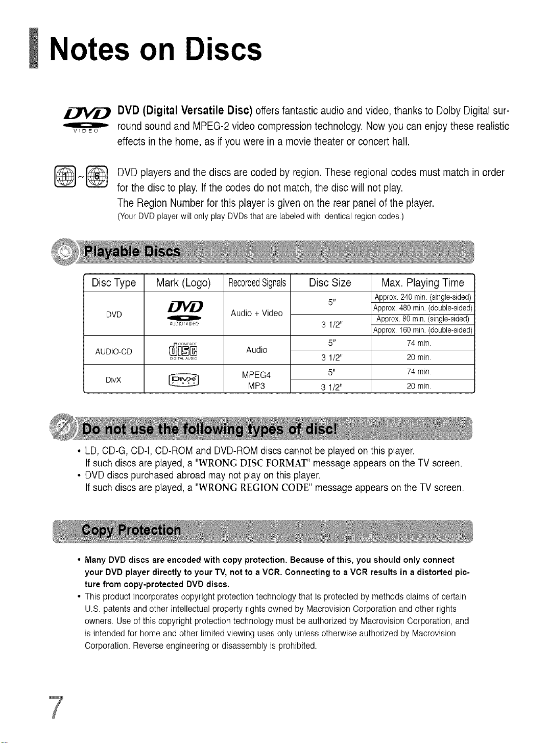
Disc Type
DVD
AUDIO-CD
DivX
Mark (Logo)
o
AUDIO/VIDeO
DIGITALAUDIO
RecordedSignals
Audio + Video
Audio
MPEG4
MP3
Disc Size
5"
3 1/2"
5"
3 1/2"
5"
3 1/2"
Max. Playing Time
Approx.240rain.(single-sided)
Approx.480min.(double-sided)
Approx.80 rain.(single-sided)
Approx.160min.(double-sided)
74min.
20min.
74rain.
20rain.
• LD,CD-G, CD-t, CD-ROM and DVD-ROM discs cannot be played on this player.
If such discs are played, a "WRONG DISC FORMAT" message appears onthe TV screen.
• DVDdiscs purchased abroad may not play on this player.
If such discs are played, a "WRONG REGION CODE" message appears on the TV screen.
Many DVD discs are encoded with copy protection. Because of this, you should only connect
your DVD player directly to your TV, not to a VCR. Connecting to a VCR results in a distorted pic-
ture from copy-protected DVD discs.
This product incorporates copyright protection technology that is protected by methods claims of certain
U.S. patents and other intellectualproperty rights owned by Macrovision Corporation and other rights
owners. Use of this copyright protection technology must be authorized by Macrovision Corporation, and
is intended for homeand other limited viewing uses only unless otherwise authorized by Macrovision
Corporation. Reverse engineering or disassembly is prohibited.
Page 9
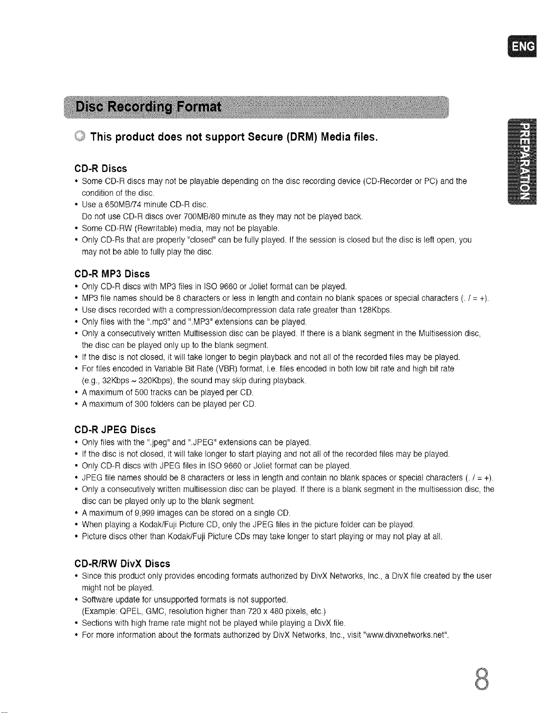
_ This product does not support Secure (DRM) Media files.
CD-R Discs
• Some CD-R discs may notbe playable depending on the disc recording device (CD-Recorder or PC) and the
condition of the disc.
• Use a 650MB/74 minuteCD-R disc.
Do not useOD-R discs over 700MB/80 minute asthey may not be played back.
• Some OD-RW (Rewritable) media, may not be playable.
• Only CD-Rs that are properly "closed" can be fully played. Ifthe session is closed butthe disc is left open, you
may not be able to fully play the disc.
CD-R MP3 Discs
• Only CD-R discs with MP3 files in ISO 9660 or Joliet format can be played.
• MP3 file names should be 8 characters or less in length and contain no blank spaces or special characters (. / = +).
• Use discs recorded with a compressiontdecompression data rate greater than 128Kbps.
• Only files with the "rap3" and ".MP3" extensions can be played.
• Only aconsecutively written Multisession disc can be played. If there is ablank segment inthe Multisession disc,
the disc can be played only upto the blank segment.
• If the disc is not closed, it will take longer to begin playback and not allof the recorded files may be played.
• For files encoded in Variable Bit Rate (VBR) format, i.e.files encoded in both low bit rate and high bit rate
(e.g., 32Kbps ~ 320Kbps), thesound may skip during playback.
• A maximum of 500 tracks can be played per CD.
• A maximum of 300 folders can be played per OD.
CD-R JPEG Discs
• Only files with the ".jpeg" and ".JPEG" extensions can be played.
• If the disc is not closed, it will take longer to start playing and not all of the recorded files may be played.
• Only CD-R discs with JPEG files in ISO9660 or Joliet format can be played.
• JPEG file names should be 8 characters or less in length andcontain no blankspaces or special characters (. / = +).
• Only aconsecutively written multisession disc can be played. If there is ablank segment inthe multisession disc, the
disc can be played only up to the blank segment.
• A maximum of 9,999 images can be stored on a single OD.
• When playing a Kodak/Fuji Picture CD_only the JPEGfiles in the picture folder can be played.
• Picture discs other than Kodak/Fuji PictureODs maytake longer to start playing or may not play at all.
CD-R/RW DivX Discs
• Since this product only provides encoding formats authorized by DivX Networks, Inc., a DivX file created by the user
might not be played.
• Software update for unsupported formats is not supported.
(Example: QPEL, GMO,resolution higher than 720 x 480 pixels, etc.)
• Sections with highframe rate might not be played while playing a DivX file.
• For more information about the formats authorized by DivX Networks, Inc.,visit "www.divxnetworks.net'.
Page 10
Description
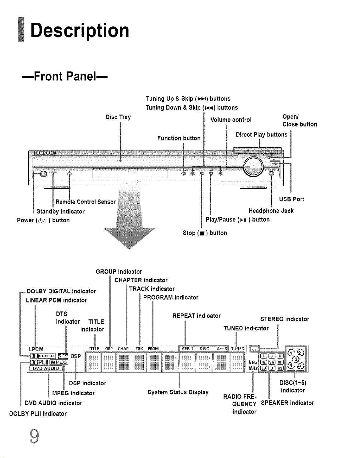
--Front Panel--
Standby indicator
Power (0/I) button
Disc Tray
Tuning Up & Skip (=,_l) buttons
Tuning Down & Skip(_) buttons
Volume control
Play/Pause (H) button
Open/
Close button
• ) button
Stop
GROUP indicator
CHAPTER indicator
DOLBY DIGITALindicator
LINEAR PCMindicator
DTS
indicator TITLE
DOLBY PLII indicator indicator
TRACK indicator
PROGRAM indicator
REPEAT indicator
QUENCY SPEAKER indicator
STEREO indicator
Page 11
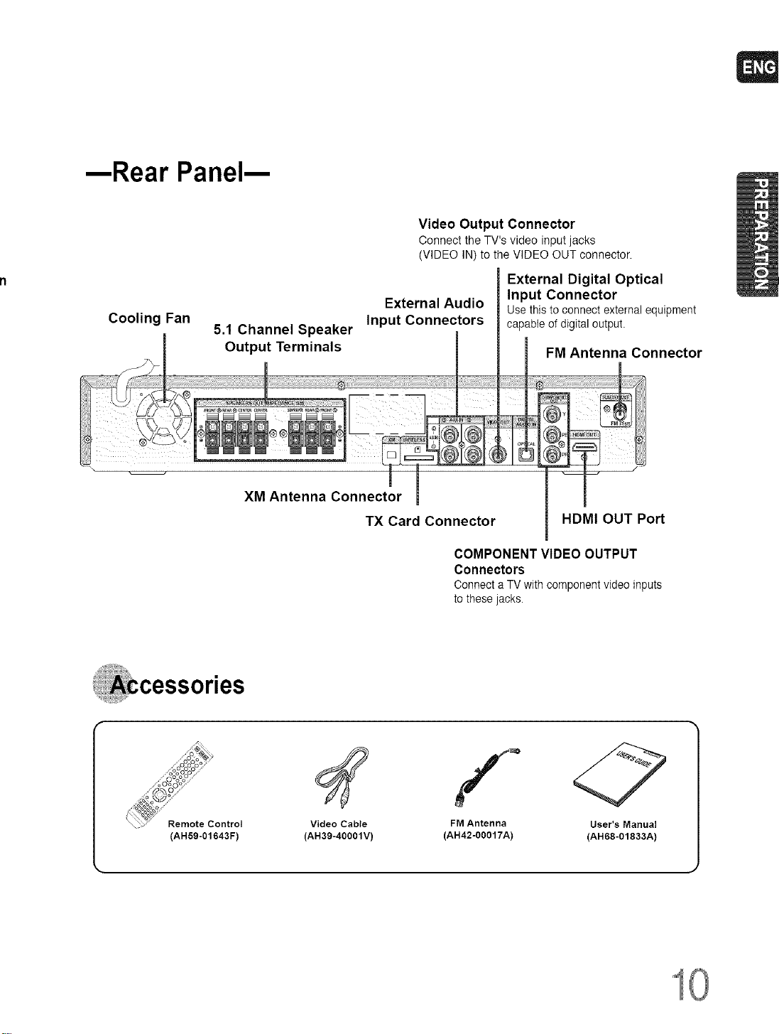
--Rear Panel--
Cooling Fan
5.1 Channel Speaker
Output Terminals
XM Antenna Connector
Video Output Connector
Connect the TV's video input jacks
(VIDEO IN) to the VIDEO OUT connector.
External Audio
Input Connectors
TX Card Connector
COMPONENT VIDEO OUTPUT
Connectors
ConnectaTV with componentvideoinputs
to these jacks.
External Digital Optical
Input Connector
Usethis toconnect externalequipment
capableofdigital output.
FM Antenna Connector
HDMI OUT Port
_OooOo_
......oO:Oo:_.....
......._o ......
...._o_
Remote Control
(AH59-01643F)
Video Cable
(AH39-40001V)
FM Antenna User's Manual
(AH42-00017A) (AH68-01833A)
10
Page 12
Description
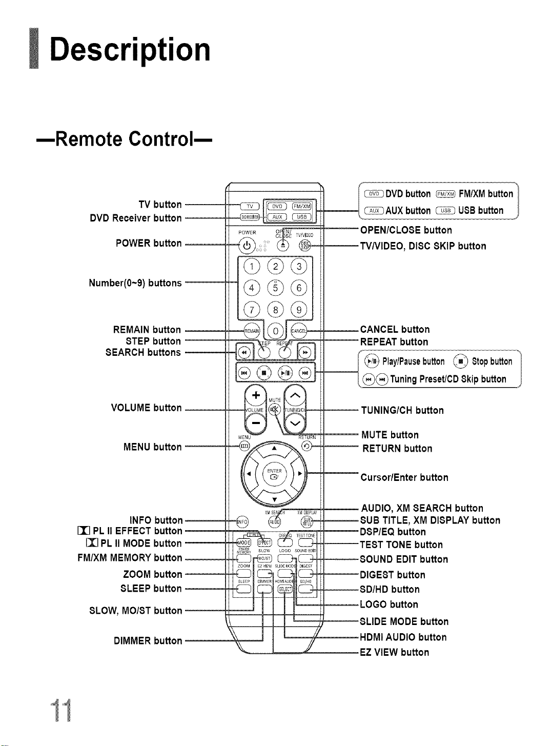
--Remote Control--
TV button
DVD Receiver button
POWER button
Number(O~9)buttons
REMAIN button
STEP button
SEARCH buttons
button
DISC 8KIP button
button
__ Play/Pausebutton_ 8topbutton"
/,@(_)Tuning Preset/CD8kip button J
VOLUME button
MENU button
INFO button
II] PLII EFFECT button
[I] PL II MODE button
FM/XM MEMORY button
ZOOM button
SLEEP button
SLOW, MO/ST button
DIMMER button
MUTE button
RETURN button
XM SEARCH button
XM DISPLAYbutton
button
TONE button
EDIT button
button
button
button
MODE button
HDMIAUDIO button
EZVIEW button
Page 13
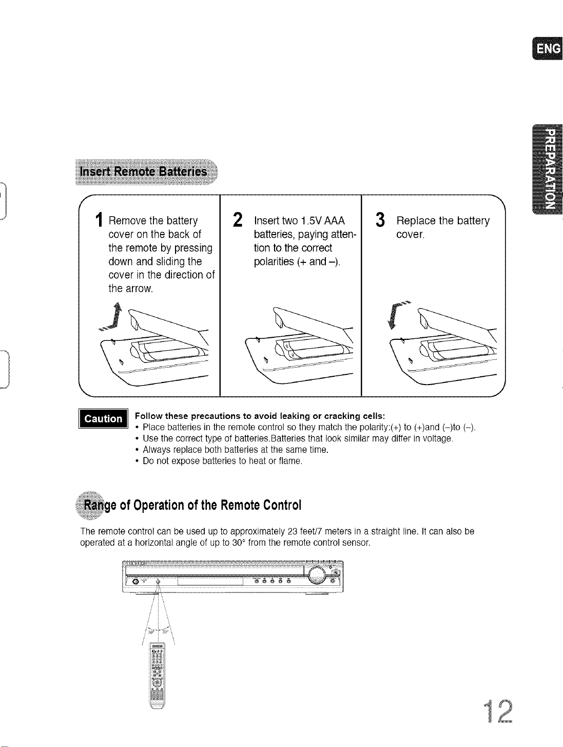
Remove the battery
cover on the back of
the remote by pressing
down and sliding the
cover in the direction of
the arrow.
Follow these precautions to avoid leaking or cracking cells:
• Place batteries in the remote control so they match the polarity:(+) to (+)and (-)to (-).
• Use the correct type of batteries.Batteries that look similar may differ in voltage.
• Always replace both batteries at the same time.
• Do not expose batteries to heat or flame.
2 Insert two 1.5V AAA
batteries, paying atten-
tion to the correct
polarities (+ and -).
_ge ofOperationof theRemoteControl
3 Replace the battery
cover.
J
The remote control can be used upto approximately 23 feet/7 meters in a straight line. It can also be
operated at a horizontal angle of up to 30° from the remote control sensor.
12
Page 14
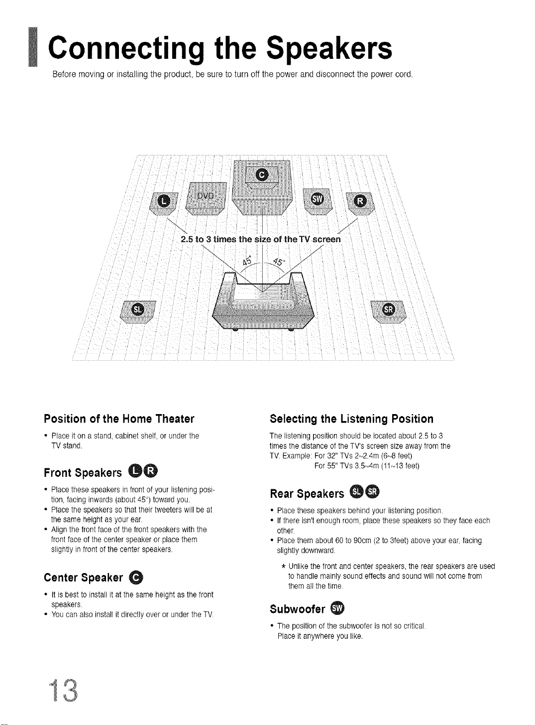
Connecting the Speakers
Before movingor installingthe product, be sure to turn off the power and disconnect the power cord.
2.5 to 3 times the size of theTV screen
Position of the Home Theater
• Place iton a stand, cabinet shelf, or under the
TV stand.
Front Speakers _O
• Place these speakers in front of your listening posi-
tion, facing inwards (about 45°) toward you.
• Place the speakers so that their tweeters will be at
the same height asyour ear.
• Align the front face of the front speakers with the
front face of the center speaker or place them
slightly infront of the center speakers
Center Speaker
• it is best to install it atthe same height as the front
speakers.
• You can also install it directly over orunder the TV
/
Selecting the Listening Position
The listening position should be located about 2.5 to 3
times the distance of the TV's screensize away from the
TV. Example: For 32" TVs 2_2.4m (6_8 feet)
For 55" TVs 3.5_4m (11_!3 feet)
Rear Speakers _)
• Place these speakers behind your listening position.
• If there isn't enough room, place these speakers so they face each
other
• Place them about 60 to 90cm (2 to 3feet) above your ear, facing
slightly downward.
* Unlike the front and center speakers, the rear speakers are used
to handle mainly sound effects and sound wil! not come from
them al! the time.
Subwoofer
• The position of the subwoofer is not so critical
Place it anywhere you like
13
Page 15
f
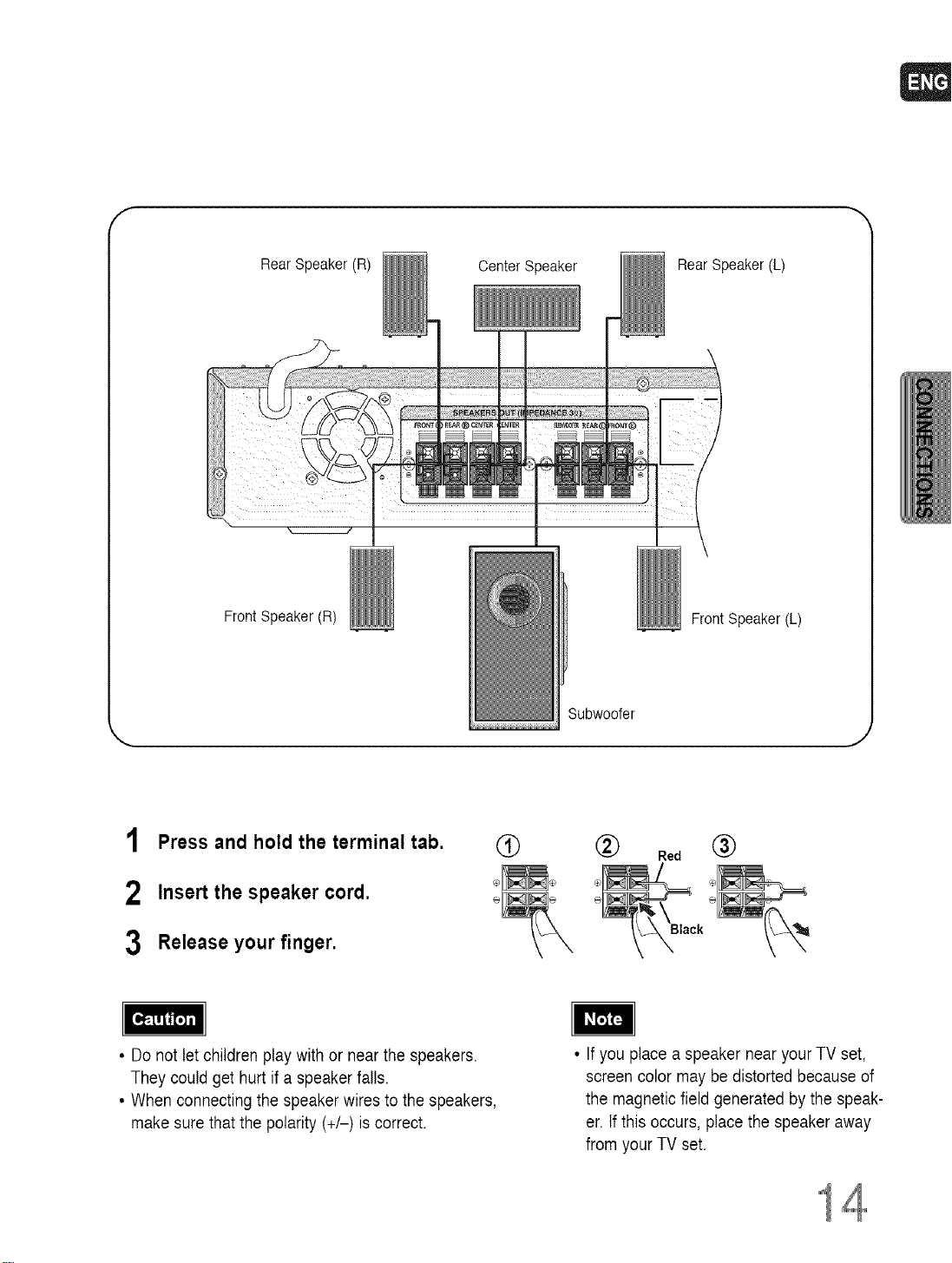
Rear Speaker (R)
Front Speaker(R)
Center Speaker Rear Speaker (L)
Front Speaker (L)
Subwoofer
1 Press and hold the terminal tab.
2 Insert the speaker cord.
3 Release your finger.
• Do not let children play with or near the speakers.
They could get hurt if a speaker falls.
• When connecting the speaker wires to the speakers,
make sure that the polarity (+/-) iscorrect.
®
(_) Red @
Black
• Ifyou place a speaker near your TV set,
screen color maybe distorted because of
the magnetic field generated bythe speak-
er. Ifthis occurs, place the speaker away
from your TV set.
14
Page 16
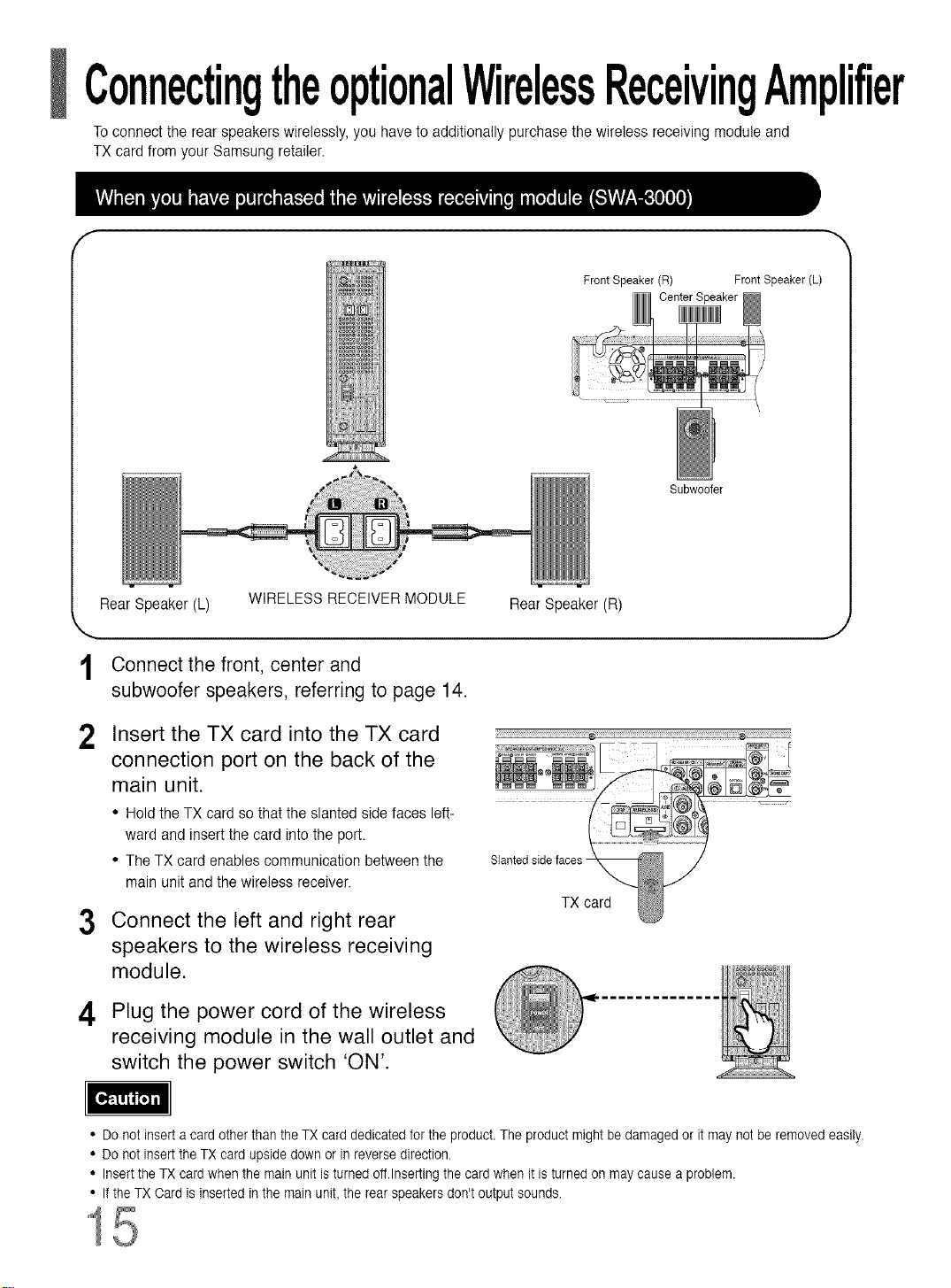
ConnectingtheoptionalWirelessReceivingAmplifier
Toconnect the rear speakers wirelessly, you have to additionally purchase the wireless receiving module and
TX card from your Samsung retailer.
f
Rear Speaker (L) WIRELESS RECEIVERMODULE Rear Speaker (R)
Connect the front, center and
1
subwoofer speakers, referring to page 14.
Insert the TX card into the TX card
2
connection port on the back of the
main unit.
• Hold the TX card so that the slanted side faces left-
ward and insert the card into the port.
• The TX card enables communication between the
main unit and the wireless receiver.
Connect the left and right rear
3
speakers to the wireless receiving
module.
ii¸¸ _ _iiiiiii;i;i ¸
Slanted side faces -
TX card
FrontSpeaker(R) FrontSpeaker(L)
CenterSpeaker
Subwoofer
Plug the power cord of the wireless
4
receiving module in the wall outlet and
switch the power switch 'ON'.
• Do not insert a card other than the TX card dedicated for the product. The product might be damaged or it may not be removed easily.
• Do not insert the TX card upside down or in reverse direction.
• Insert the TX card when the main unit is turned off.Inserting the card when it is turned on may cause a problem.
• If the TX Card is inserted in the main unit,the rear speakers don't output sounds
15
Page 17
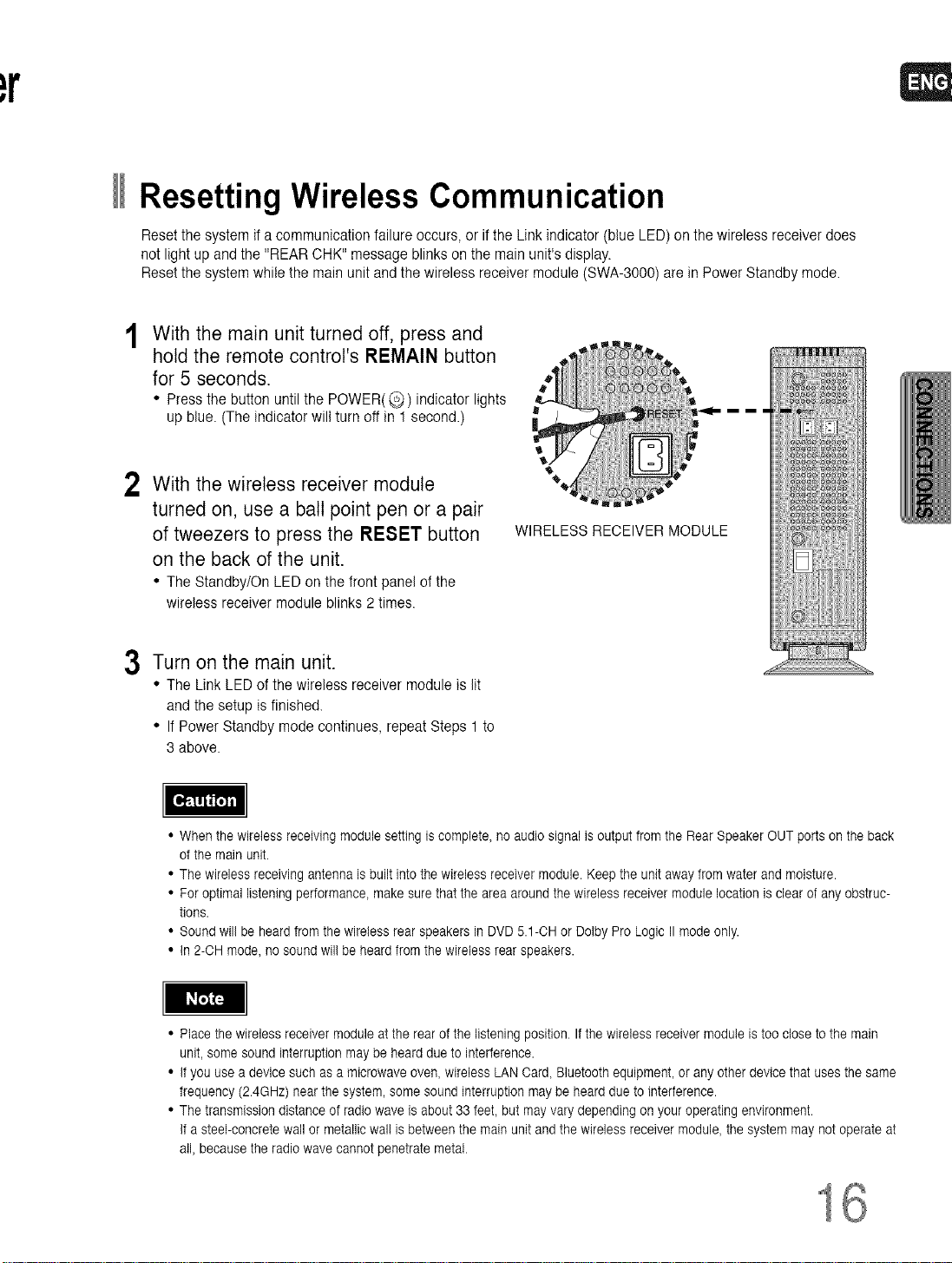
Resetting Wireless Communication
Reset the system if a communication failure occurs, or ifthe Link indicator (blue LED)on the wireless receiver does
not light up and the "REAR CHK" message blinks on the main unit's display.
Reset the system while the main unit and the wireless receiver module (SWA-3000) are in Power Standby mode.
With the main unit turned off, press and
hold the remote control's REMAIN button
for 5 seconds.
• Press the button until the POWER( @ ) indicator lights
up blue. (The indicator will turn oft in 1 second.)
With the wireless receiver module
2
turned on, use a ball point pen or a pair
of tweezers to press the RESET button
on the back of the unit.
• The Standby/On LED on the front panel of the
wireless receiver module blinks 2 times.
Turn on the main unit.
3
• The Link LED of the wireless receiver module is lit
and the setup is finished.
• If Power Standby mode continues, repeat Steps 1 to
3 above.
WIRELESS RECEIVER MODULE
• When the wireless receiving module setting is complete, no audio signal is output from the Rear Speaker OUT ports on the back
of the main unit.
• The wireless receiving antenna is built into the wireless receiver module. Keep the unit away from water and moisture.
• For optimal listening performance, make sure that the area around the wireless receiver module location is clear of any obstruc-
tions.
• Sound will be heard from the wireless rear speakers in DVD 5.1-OH or Dolby Pro Logic II mode only.
• in 2-OH mode, no sound wil! be heard from the wireless rear speakers.
I_J_
• Place the wireless receiver module at the rear of the listening position. If the wireless receiver module is too close to the main
unit, some sound interruption may be heard due to interference.
• if you use a device such asa microwave oven, wireless LAN Card, Bluetooth equipment, or any other device that uses the same
frequency (2.4GHz) near the system, some sound interruption may be heard due to interference.
• The transmission distance of radiowave is about 33 feet, but may vary depending on your operating environment.
if a steel-concrete wallor metallic wal! is between the mainunit and the wireless receiver module, the system may not operate at
all, because the radio wave cannot penetrate metal.
Page 18
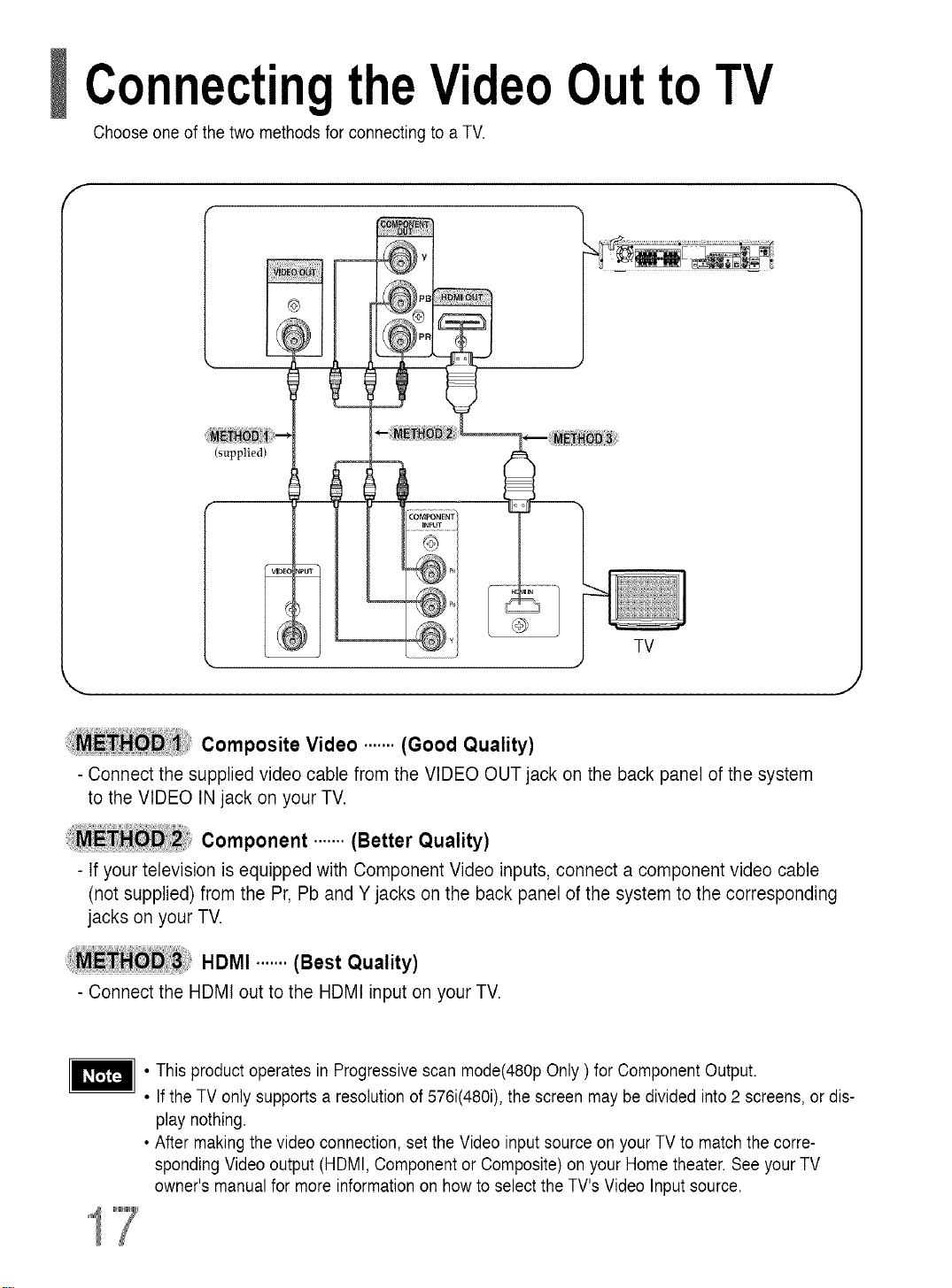
ConnectingtheVideoOutto TV
Choose one of the two methods for connecting toa TV.
f
(supplied)
TV
i_iE_ Composite Video ....... (Good Quality)
- Connect the supplied video cable from the VIDEO OUT jack on the back panel of the system
to the VIDEO IN jack on your TV.
Component ....... (Better Quality)
- If your television is equipped with Component Video inputs, connect a component video cable
(not supplied) from the Pr, Pb and Y jacks on the back panel of the system to the corresponding
jacks on your TV.
HDMI .......(Best Quality)
- Connectthe HDMI out to the HDMI input on yourTV.
• Thisproduct operates in Progressive scan mode(480p Only ) for Component Output.
• Ifthe TV only supports a resolution of 576i(480i), the screen may be divided into 2 screens, or dis-
play nothing.
• After making the video connection, setthe Video input source on your TV to match the corre-
sponding Videooutput (HDMI, Component or Composite) on your Home theater. See your TV
owner's manual for more information on how to select the TV's Video Input source.
Page 19
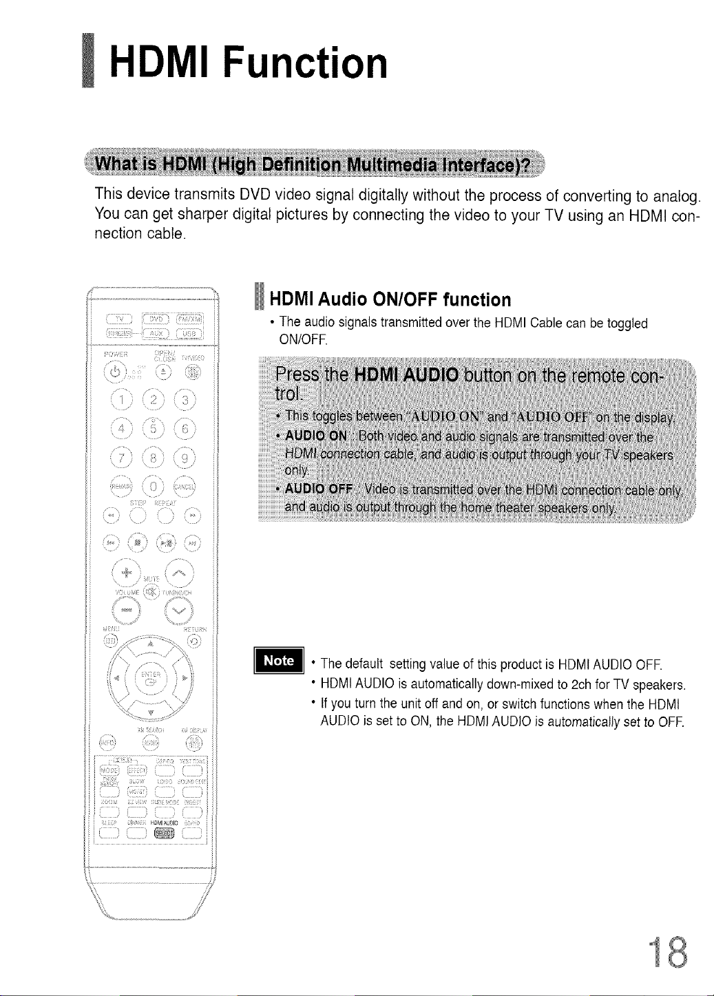
HDMI Function
This device transmits DVD video signal digitally without the process of converting to analog.
You can get sharper digital pictures by connecting the video to your TV using an HDMI con-
nection cable.
HDMI Audio ON/OFF function
• The audio signalstransmitted over the HDMI Cable can be toggled
ON/OFR
• The default setting value of this product is HDMtAUDIO OFR
• HDMtAUDIO is automatically down-mixed to 2ch for TV speakers.
• Ifyou turn the unit off and on, or switchfunctions when the HDMt
AUDIO is set to ON, the HDMI AUDIO is automatically set to OFF.
Page 20
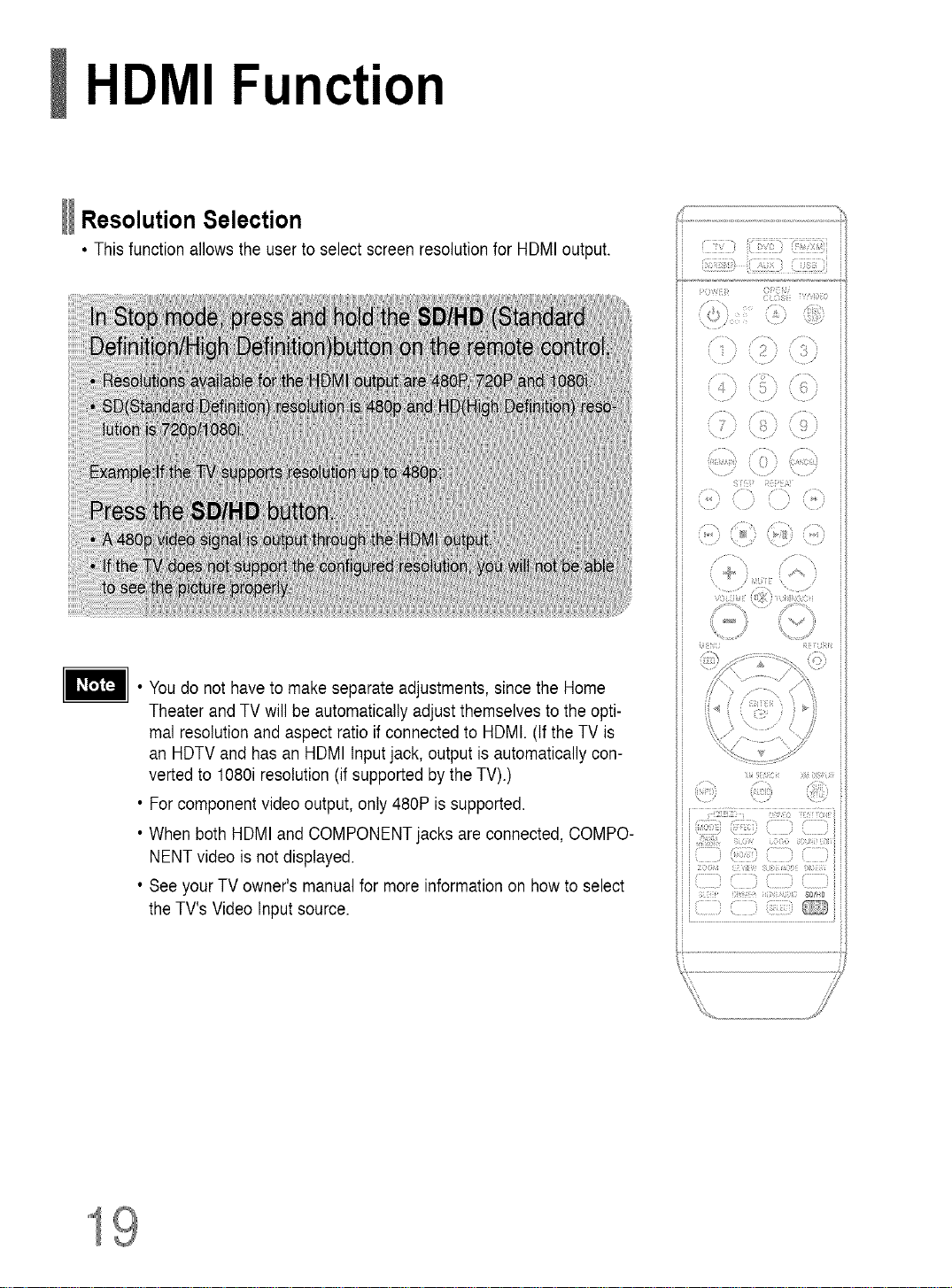
HDMI Function
Resolution Selection
• This function allows the user to select screenresolution for HDMI output.
r¸ :_:_} i1]!77!}(7!!7!iii!7!i!_i
• Youdo not have to make separate adjustments, sincethe Home
Theater and TV will beautomatically adjust themselvesto the opti-
mal resolution andaspect ratio if connected to HDMI. (If the TV is
an HDTV and has an HDMI Inputjack, output is automatically con-
verted to 1080i resolution(if supportedby the TV).)
• For component video output, only 480P is supported.
• When both HDMI and COMPONENTjacks are connected, COMPO-
NENT video is not displayed.
• Seeyour TV owner's manual for more information on how to select
the TV's Video Input source.
(, ( /
x, \ ,,
i + 7) /
c
/
U ) i) )
( , ; }
/ /
\
I"
{71r{ i r,i
..... x.....
\
/
::: ()
ii77L i i{J i
_;i!;i,i...... !i!Ti;] , ........_,_
(!iiTii))(ZI)
_rO_b4 _7,ii; i;iii)ir4)!:i i)_tK
........_ _ il]]ilr ,
i_i:_!iuf;i; SOlO
71_iiii7
19
Page 21
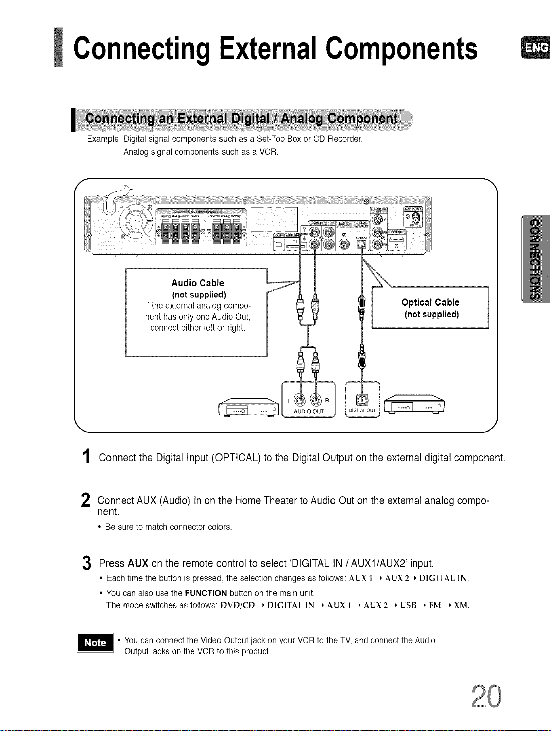
ConnectingExternalComponents
Example: Digital signal components such as a Set-Top Box or CD Recorder.
Analog signal components such as a VCR
Audio Cable
(not supplied)
Ifthe external analog compo-
nent hasonly one Audio Out,
connect either left or right.
Optical Cable
(notsupplied)
AUDIO OUT
Connect the Digital Input (OPTICAL) to the Digital Output on the external digital component.
2 Connect AUX (Audio) Inon the Home Theater to Audio Out on the external analog compo-
nent.
• Be sure to match connector colors.
3 Press AUX on the remote control to select 'DIGITAL IN /AUX1/AUX2' input.
• Each time the button is pressed, the selection changes as follows: AUX 1 -* AUX 2-* DIGITAL IN.
• You can also use the FUNCTION button on the main unit.
The mode switches as follows: DVD/CD -* DIGITAL IN -* AUX 1 -* AUX 2 -* USB -* FM -* XM.
You can connect the Video Output jack on your VCR to theTV, and connect the Audio
Output jacks on the VCRto this product.
Page 22
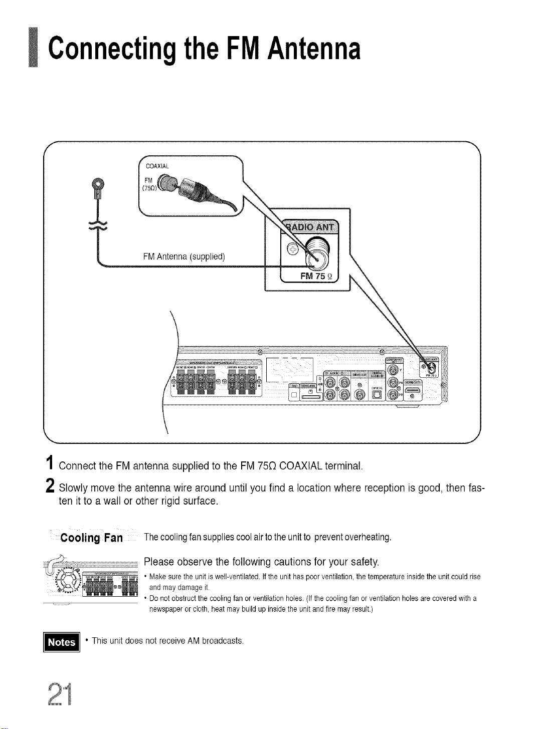
ConnectingtheFMAntenna
f
COAXIAL
FMAntenna (supplied)
1Connect the FM antenna supplied to the FM 750 COAXIAL terminal.
2 Slowly move the antenna wire around until you find a location where reception is good, then fas-
ten it to a wall or other rigid surface.
Cooling Fan Thecoolingfansuppliescool airtotheunitto preventoverheating.
Please observe the following cautions for your safety.
• Makesure the unit is well-ventilated.If the unit haspoor ventilation,the temperature inside the unit could rise
and may damage it.
• Donot obstructthe coolingfan or ventilation holes.(If thecooling fan or ventilationholes arecovered with a
newspaperorcloth, heat may buildup insidethe unit and fire may result.)
• This unitdoes not receive AM broadcasts.
Page 23
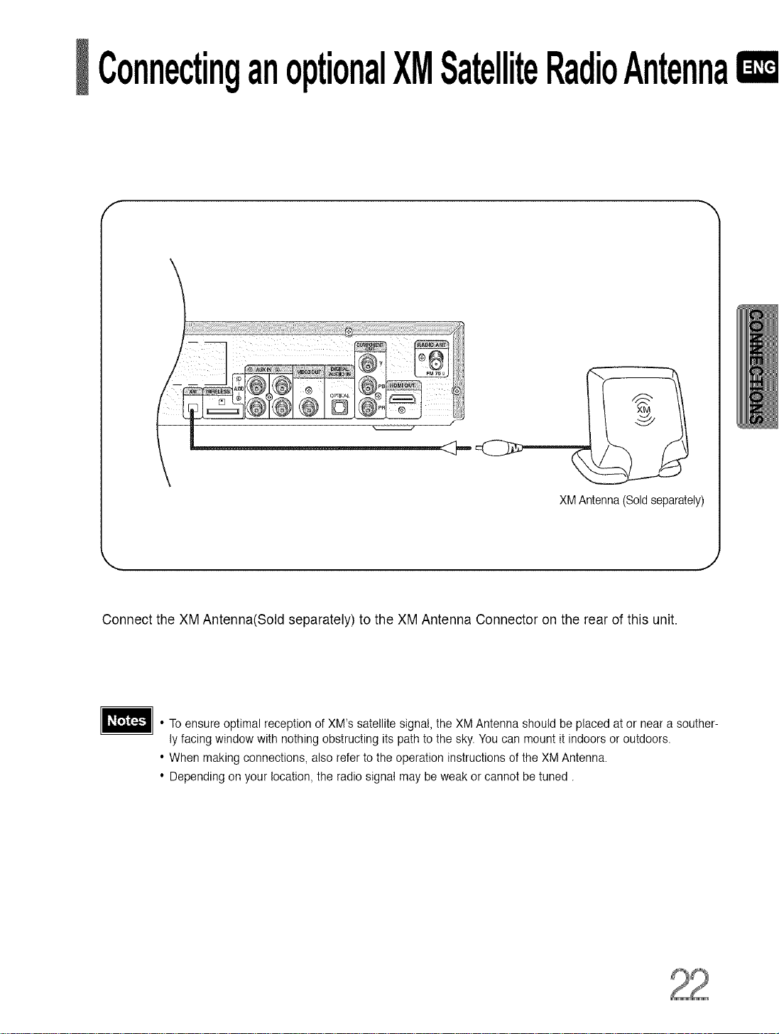
ConnectinganoptionalXMSatelliteRadioAntennaIXD
XMAntenna(Soldseparately)
Connect the XM Antenna(Sold separately) to the XM Antenna Connector on the rear of this unit.
• To ensure optimal reception of XM's satellite signal, the XM Antenna should be placed at or near a souther-
ly facing window with nothing obstructing itspath to the sky. You can mount it indoors or outdoors.
• When making connections, also referto the operation instructions of the XM Antenna.
• Depending on your location, the radio signal may be weak or cannot be tuned.
Page 24
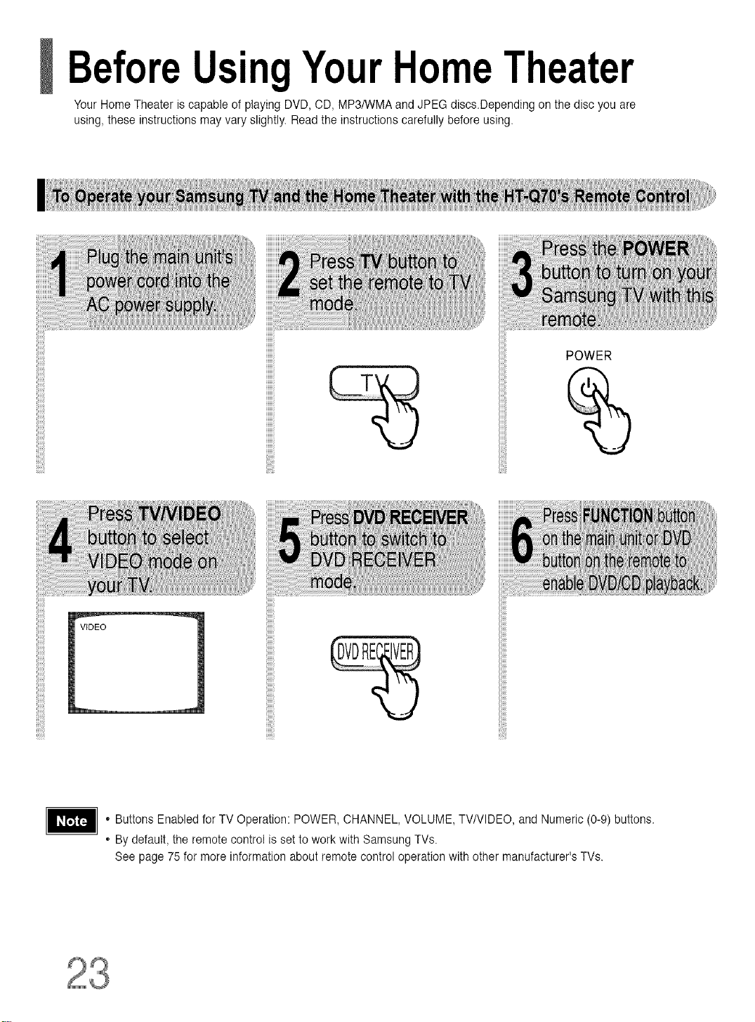
BeforeUsingYourHomeTheater
Your Home Theater iscapable of playing DVD, CD, MP3/WMA and JPEG discs.Depending on the disc youare
using, these instructions may vary slightly. Readthe instructions carefully before using.
POWER
, Buttons Enabled forTV Operation: POWER, CHANNEL, VOLUME, TV/VlDEO, and Numeric (0-9) buttons.
, Bydefault, the remote control is set to work with Samsung TVs.
See page 75 for more information about remote control operation with other manufacturer's TVs.
Page 25
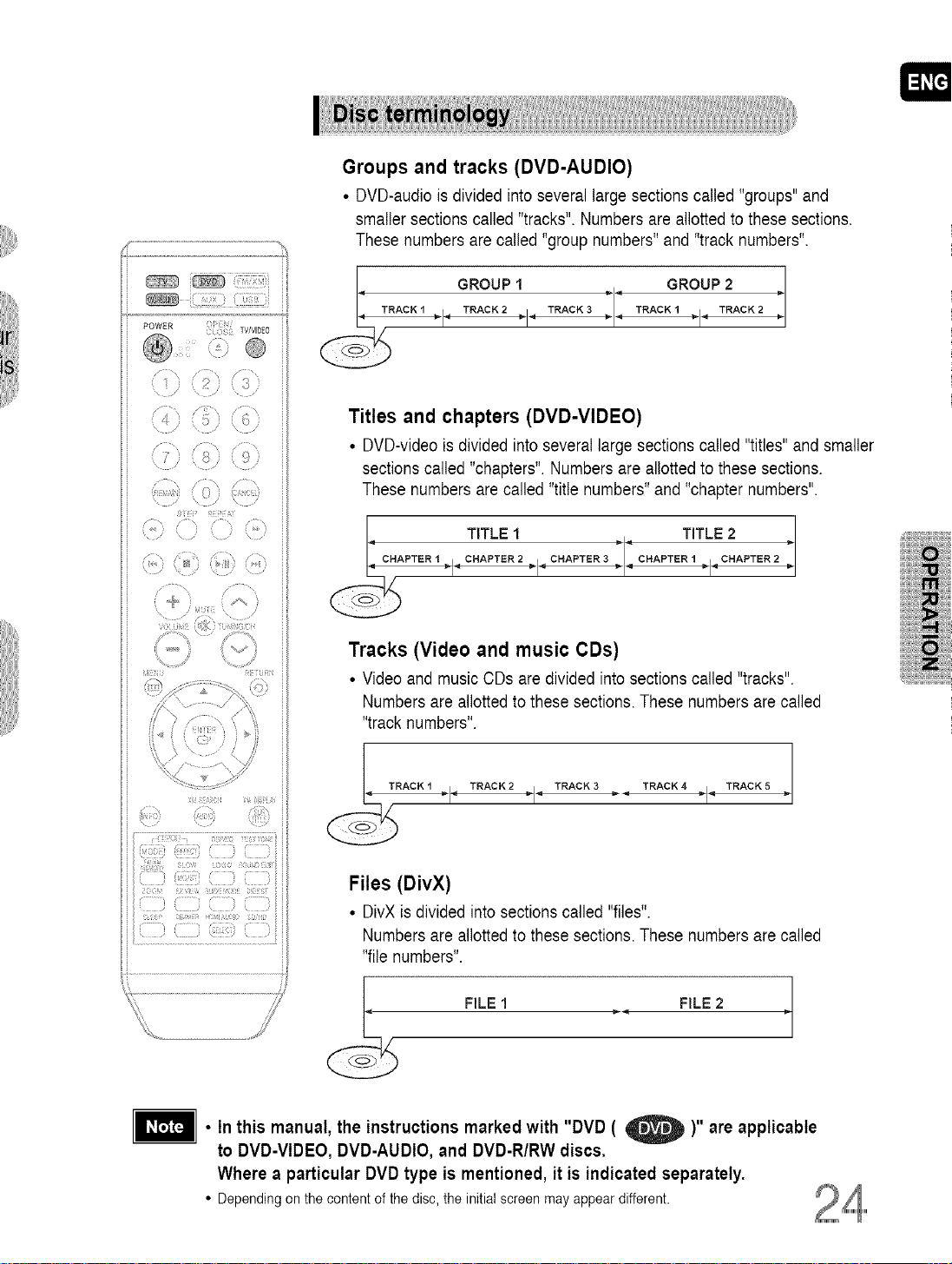
Groups and tracks (DVD-AUDIO)
• DVD-audiois divided into several large sections called "groups"and
smaller sections called "tracks". Numbers are allotted to these sections,
These numbers are called"group numbers" and "track numbers",
POWER ( /
C S_ TWVlD_O
® ®
© (#
@
_E_8 dR
I TRACKI < GROUPTRACK2._1 TRACK3 :: TRAcKIGROUPTRACK22
Titles and chapters (DVD-VIDEO)
• DVD-video is divided into several large sections called "titles" andsmaller
sections called "chapters". Numbers are allotted to these sections.
These numbers are called "title numbers" and "chapter numbers".
TITLE1 TITLE2
Tracks (Video and music CDs)
• Videoand music CDs are divided into sections called "tracks".
Numbers are allottedto these sections. These numbers arecalled
"track numbers",
Files (DivX)
• DivXis divided into sections called "files".
Numbers are allottedto these sections. These numbers arecalled
"file numbers".
FILE1 FILE 2
• In this manual, the instructions marked with "DVD ( _ )" are applicable
to DVD-VIDEO, DVD-AUDIO, and DVD-R/RW discs.
Where a particular DVD type is mentioned, it is indicated separately.
• Depending on the content of the disc, the initial screen may appear different.
Page 26
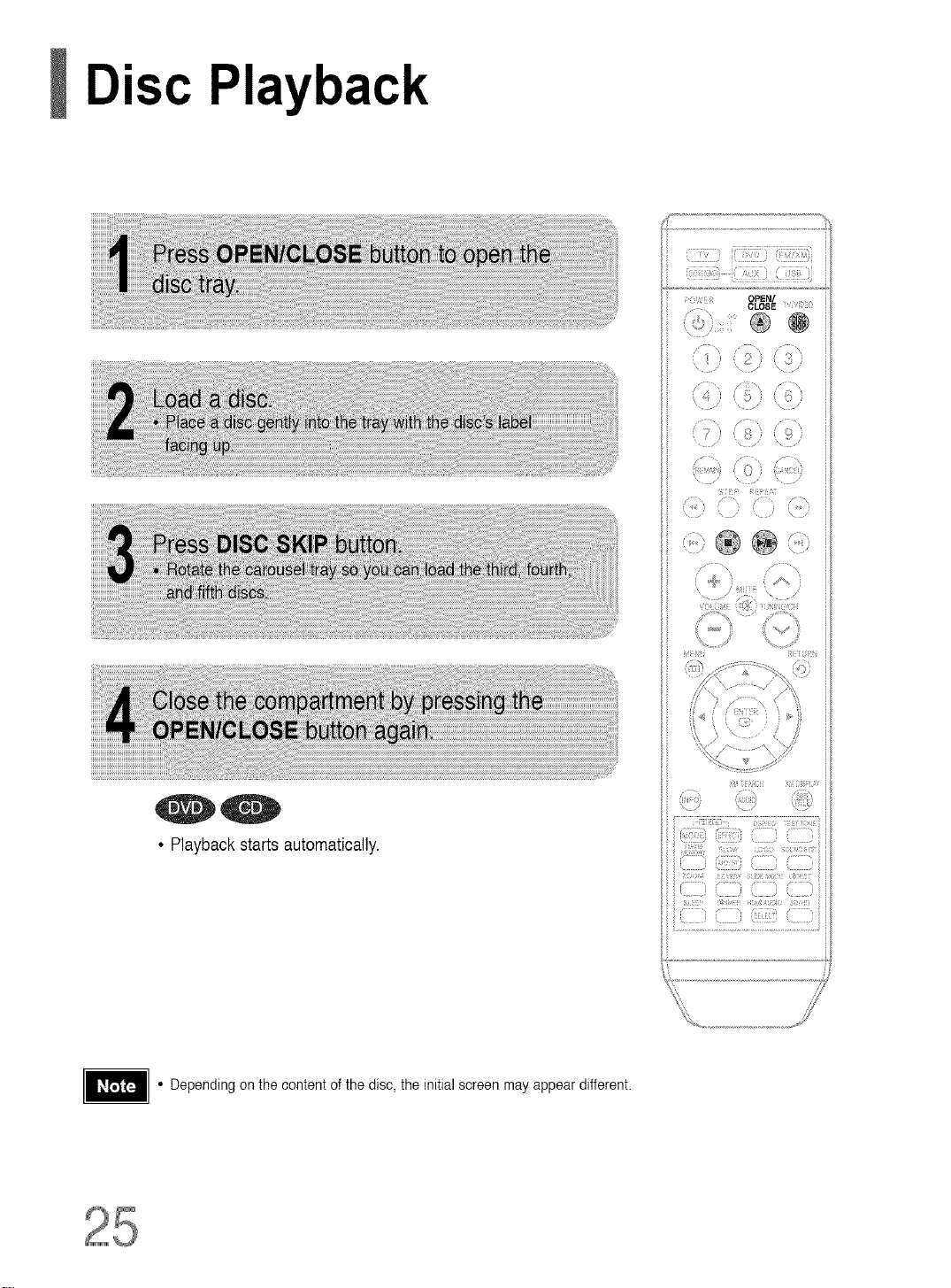
Disc Playback
L
• Playback starts automatically.
• Depending on the content of the disc, the initial screen may appear different.
: I
)
,/
Page 27

Selectinga DiscintheDiscchanger
The DVD/CD function is automatically selected when Disc Skip is pushed.
• if the disc selected is not loaded, the nextdisc is played automatically.
To stop playback, press STOP during playback.
• If pressed once, "PRESSPLAY" is displayed and the stop position will be stored in memory.
IfPLAY/PAUSE ( I_ll ) button or ENTER button is pressed, playback resumes from the stop position.
(This function works only with DVDs.)
• If pressed twice, "STOP" is displayed, and if PLAY/PAUSE(l_l) button is pressed, playback starts from the
beginning.
To temporarily pause playback, press PLAY/PAUSE during playback.
• To resume playback, press PLAY/PAUSE (_bill) button again.
Page 28

MP3/WMA-CD Playback
Data CDs CD-ROM, CD-R, CD-RW) encoded in MP3/WMA format can be played.
{:¸:!17:}}i(::_7:!7}},{:!!_71!_!i!;_i
OPEN/
CLOSE D0
®
(5)
} 0 }
J::' b
/ /
(7} )
rT}}: <[:i
i
® @ (?::>
• The MP3/WMA menu screenwill appear
and playback will start.
• The appearance of the menu depends on
the MP3/WMA disc.
• WMA-DRM files cannot be played.
• To select another album and track,
repeat Steps 2 and 3 above.
• Use A _' to select the track.
• Depending on the recording mode, some MP3/WMA-CDs may not play.
• Table of contents of a MP3-CD varies depending onthe MP3/WMA track for-
mat recorded on the disc.
To play a file icon in the screen
Press the 4 !,. A T button when it is in stop
statusand select a desired iconfrom the top
part of the menu.
• To play music files only, select the _ Icon.
• To view image files only,select the _ Icon.
• To view movie files only, select the _ Icon.
• To select all files select the _ Icon.
• MusicFile Icon
• ImageFile Icon
• MovieFile Icon
• All FileIcon
Page 29

DisplayingDiscInformation
You can view disc playback information on the TV screen.
0 0
0 0 0
The information DisP!aydisap_ ]-he information Display disap_
pears from the screen pears from the screen
0
The info[mation DisPlaydisap-
pears from the screen
• Depending on the disc, the disc informa-
tion display may appear different.
• Depending on the disc, you can also
select DTS, DOLBY DIGITAL,or PRO
LOGIC.
DVDdisplay
_D CDdisplay
TITLEdisplay _ LR STEREO(L/R)disphy
GROUPdisplay [][][_ DOLBYDIGITALdisplay
,ql'& _ ANGLEdisplay
_,I,V CHAPTERdisplay
• t_ appears on the TV screen!
Ifthis symbol appears onthe TV screen while buttons are being operated,
that operation is not possible with the disc currently being played.
• What is a Group?
Asection of tracks contained in a DVD-AUDIO disc.
• What is a Title?
A moviecontained in a DVD-VlDEO disc.
• What is a Chapter?
Each title on a DVD disc is divided into severalsmaller sections called
"chapters".
• What is a Track (File)?
Asection of video or amusic file recordedon a DVD-AUDIO,CD, or MP3-
C,D
ELAPSEDTIMEdisplay
(_ _) REPEATPLAYBACKdisplay
]AUDIO LANGUAGEdisphy
DIGITAL
TRACK(FILE)display
SUBTITLEdisplay
Page 30

JPEG File Playback, ,
Images captured with a digital camera or camcorder,or JPEG files on a PC can be stored on a CD and then
played backwith this Home Theater.
Slide Mode
OPEN/
CLOSE L7
\ ,/
i _ ) 0 i t ,J
\ " i: \ ,
,4 ;
{ 7 g )
........................' 0};
[;F 2} :J ;r
• Playback starts automatically.
• Each time the button is pressed, the image makes the transition as follows:
Fromtoptobottom
From bottom to top
0
®
Q
Rectangular shape in the center
41-
Vertical blinds effect
Each time a new image is displayed, slide modes
(1_11) wil! be applied randomly and automatically.
Cancels the slide mode
ts _ _ to skip to the next slide.
i; ti }ii)
=i7_
Digest Function
You can view 9 JPEG images on the TV screen.
• JPEG files will beshown in
9 windows.
• The selected image is playedfor 5 seconds before moving
to the next image.
O
-_iew the previous or next image with 9 windows, press_
Rotate/Flip Function
,& button: Flip Vertically
®@@÷@@@@®
4 button: Rotate 90°
Counterclockwise
Original Image
V button: Flip Horizontalty
• The maximum resolutions supported bythis product are 5120 x 3480 (or 19.0 MPixel)for
standard JPEG files and 2048 x 1536 (or 3.0 MPixel) for progressive image files.
_. button: Rotate 90° Clockwise
Page 32

DivX Playback
The functions on this page applyto DIVX disc playback.
Skip Forward/Back
/," ",\ i,"L:, /" ,,,
4
7;
Fast playback
5 Minute Skip function
Zoom Function
7
\ ,
\ ......... \ /
);
® ®
® @ ®
i iii ii [)ii
• Each time you press the button,
your selection will toggle between
"ZOOM X2" and "ZOOM OFF".
• DIVX file can be zoomed only in ZOOM X2 mode.
• DivX files have .Avi file extensions, however,not all .Avi files are DivX
and may not be playable inthis unit.
Page 33

Subtitle Display
• Each time you pressthe button,your selection will toggle between "SUBTITLE (1/1, 1/2 ...)"and
"SUBTITLE OFF".
• If the disc has only one subtitle file, it will be played automatically
• See number 2 (Caption Function) below for more details concerning Subtitle usage with DIVX discs.
Audio Display
• If there are multiple audio tracks on a disc, you can toggle between them.
...........• Each time you pressthe button,your selection will toggle between "AUDIO (1/1, 1/2 ...)"and ,,I__".
• " _ "is displayed when there is one supported languagein the disc.
DivX(Digital internet video eXpress)
DivX is a video file format developed by Microsoft and is based on MPEG4 compression technology
to provide audio and videodata over the Internet in real-time.
MPEG4 is usedfor video encoding and MP3 for audio encoding so that the users can watch a movie
at near DVD-qualityvideo and audio,
1. Supported Formats
• This product only supportsthe following media formats.If both video and audio formats are not support-
ed, the user may experience problems such as broken images or no sound.
• Supported Video Formats
WMV
Format t AVI
Supported Versions DivX3,11 ~ 5,1
• Supported Audio Formats
Format MP3 WMA
Bit Rate 80~384kbps 56~128kbps
SamplingFrequency 44.1khz
• DivX files, including audio and video files, created in the DTS format can only support up to 6Mbps.
• Aspect Ratio: Although default DivX resolution is 640*480 pixels (4:3),this product supports up to
720*480 pixels (16:9). TV screen resolutions higher than 800 will not be supported.
• When you play a disc whose sampling frequency is higher than 48khz or 320kbps, you may experi-
ence shaking on the screen during playback.
VlN2N3N7
AC3 DT8
128~384kbps 1.5Mbps
44.1/48khz 44.1khz
2. Caption Function
• You must have some experience with video extraction and editing in order to use this feature properly.
• To use the caption function, save the captionfile (*.smi) inthe samefile name as that of the DivX
media file (*.avi) within the same folder.
Example. Root Samsung_0O7CDl.avi
Samsung_007CD1.smi
• Up to 60alphanumeric characters or 30 EastAsian characters (2 byte characters such as Korean and
Chinese) for the file name.
Page 34

Checkingthe RemainingTime
Each time the REMAIN button is pressed
i! { i; fi ii L
)
i7!!7!1!7!!_ !11111!!_7!77!!17'/i
i ))(IIZ) 1)i
N(N Ngfili ii;11!i{111 Nii[7 i
, [i7i;itii}
, 7 i i .....
..............................................................................................J
Page 35

Fast/Slow Playback
Fast Playback
Slow Playback
..... ,.
• During fast playback of a CD or MP3-CD, sound is
heard only at 2x speed, and not at 4x, 8x, and 32x
speeds.
"0-
• Nosoundisheardduringslowplay-
backandstepmotionplayback.
• Reversestowplaybackdoesnot
workwith DivX.
Skipping Scenes/Songs
_ PREVIOUS
Page 36

Repeat Playback
Repeat playback allows you to repeatedly play a chapter, title, track (song), ordirectory (MP3 file).
@
@
CHAPTER
@
Repeatedly plays the selected chapter.
,O-
41,
4_
TITLE
Repeatedly plays the selected title.
GROUP
Repeatedly plays the selected group.
RANDOM
Playstracks in random order.
(Atrackthat has already been played maybe
playedagain.)
TRACK
Repeatedly plays the selected track.
DIR
Repeatedly plays all tracks inthe selected folder.
DISC
Repeatedly plays the entire disc.
OFF
OancelsRepeat Playback.
a Repeat Playback Mode in the Disc InformationScreen
1 Press INFO button twice.
2 Press Cursor _ button to move to
REPEAT PLAYBACK (_;)) display.
3 Press Cursor'v button to select the
desired Repeat Playback mode.
4 Press ENTER button.
* For MP3andJPEG discs,youcannot select Repeat
Playfrom the informationdisplayscreen.
Page 37

A-B Repeat Playback
You can repeatedly play back a designated section of a DVD.
:i
(
f_s ¸ \ / \
,,, i•_•i(!!•\>
5[ REPEAT
:> ,i @
} }
i } ?i
(1111(ii
• When ENTER button is pressed,
the selected position will be stored
in memory.
• The specified segment will be
played repeatedly.
REPEAT :A--B
O
REPEAT :A--
playback,
oetUrnto normal Cursor A
ns to select (_# OFF.
• The A-B Repeatfunction does not operate with MP3, CD or JPEG discs.
press
,T
Page 38

Step Function
Angle Function
This function allows you to view the same scene in different angles.
• Each time the button is pressed, the angle changes as follows:
(::::]ii_:::)i(::!!!!]!b(!!!:!i!]!!:!!i!)il
7
i¸¸¸¸ _"
i " ]:
_ ) ,2;
/
i:)
STEP i:)
@
...... < ,
x
iiiiiiii iiiiiij[i;_
• The Angle function works only with discs on which multiple
angles havebeen recorded, i
ii i ) iii
(,,
[ } = =: :
:i
() !)}?:........,
Page 39

Zoom(ScreenEnlarge)Function
This function allows you to enlarge a particular areaof the displayed image.
• Each time the button is pressed, the
zoom level changes as follows:
41-
• When a DivX disc is being played, only the 2:1 zoom-in is available.
EZ VIEW Function
• Each time the button is pressed, the zoom function will switch between On
and Off.
• When a movie is played in Widescreen format, black bars at the top and bot-
tom of the TV screen can be removed by pressing the EZ VIEW button.
• This function will not work if the DVD is recorded with multi-camera angle format.
• Black bars may not disappear because some DVD discs have a built-in horizontal to vertical ratio.
• This feature is not supported for DivX discs.
Page 40

BonusGroup/ NavigatingPages
Bonus Group
Some DVD-Audio discs have an extra 'bonus' group that requires a 4-digit key
number to access. See the disc packaging for details and the-key number.
• If you eject the disc, switch the power off, orunplug the player,you will need to re-enter
the key number.
Navigating Pages
• You can select the desired image from a DVD-Audio disc containing still images.
• With some discs, you may not beable to select images.
Page 41

SelectingAudio/SubtitleLanguage
AudioLanguageSelectionFunction
• Dependingonthenumberoflanguagesona
DVDdisc,a differentaudiolanguage(ENG-
LISH,SPANISH,FRENCH,etc.)isselected
eachtimethebuttonis pressed.
1
........... [] F_ I
SubtitleLanguageSelectionFunction
• To operatethisfunction,youcanalso
presstheSelectAUDIOorSelectSUB-
TITLEbu_onsonthe remotecontrol.
• Depending on the disc, the Subtitle
andAudio Language functions may
_ _o_o_|
FR (_/03 /
OFF_
not be available.
i
Page 42

PlayingMediaFilesusingtheUSBHOSTfeature
You can enjoy media files such as pictures, movies and music saved in an MP3 player, USB memory or digital camera in high
quality video with 5.1 channel home theater sound by connecting the storage device to the USB port of the home theater•
QWR (3 Ii
• "USB" appears on thedisplay screen
and then disappears.
• USB MENUscreen appears on the TV
screen and the saved file is played.
,_ LeI I_Be
) To stop playback, press the STOP (=) button.
Safe USB Removal
Toprevent damage to the memory stored in the USB device, perform safe removal
before disconnecting the USB cable.
(1) Press the Stop button twice in a row.
The display will show REMOVE 4 USB.
(2) Remove the USB cable.
Skip Forward/Back
" /) " /22;
4) ) :_
, , / ::: ) \
/ J
) ( '? } ?,rcr)
i>
® ®
f1 :[ ; J
, [i :
)
..... 3
:(r ;)r: C? r::;?
() (illl ;:
Fast playback
4"1
Page 43

1. USB devices that support USB Mass Storage vl.0.
(USB devices that operate as a removable disk in Windows
(2000 or later) without additional driver installation.)
2. MP3 Player: HDD and flash type MP3 players.
3. Digital camera: Cameras that support USB Mass Storage v1.0.
• Cameras that operate as a removable disk in Windows (2000or later) without additional driver installation.
4. USB HDD and USB Flash Drive: Devices that support USB2.0 or USBI.1.
• You may experience a difference in playback quality when you connect a USB1.1 device.
• For a USB HDD, make sure to connect an auxiliary power cord to the USB HDD for proper operation.
5. USB card Reader: One slot USB card reader and Multi slot USB card reader
• Depending on the manufacturer,the USB card reader may not be supported.
• If you install multiple memory devices into a multi card reader, you may experience problems.
6. If you use a USB extension cable, the USB device might not be recognized.
• Supported Formats
JPG
MP3
WMA
illlllllllllll_lllllllilll_lllllil_lli_lllil_lllllil_lil_llllllllllllllllllllilil
WMV
DivX
JPG .JPEG
.MP3
WMA
WMV
AVl,.ASF
80N384kbps
56N128kbps
4Mbps
4Mbps
- 640*480
- 441kHz
V8 441kHz
Vl,V2,V3,V7 720*480 441KHz_48KHz
DivX3.11_DivX5.1,Xvid 720*480 441KHz_48KHz
• CBI (Control/Bulk/Interrupt) is not supported.
• Digital Cameras that use PTP protocol or require additional program installation
when connected to a PC are not supported.
• A device using NTFS file system is not supported.
(Only FAT 16/32 (File Allocation Table 16/32) file system is supported.)
• Some MP3 players, when connected to this product,may not operate depending
on the sector size of their file system.
• The USB HOST function is not supported if a product that transfers media files by
its manufacturer-specific program is connected.
• Does not operate with Janus enabled MTP(Media Transfer Protocol) devices.
• The USB host function of this product does not support all USB devices.
For information on the supported devices, see pages 81.
Page 44

MovingDirectlyto a Scene/Song
0_
.......ii_ii_ii_ii_ii_ii_ii_ii_ii_ii_ii_ii_!ii£_!_!i_!i_!!£!!i_i!i!i!i!_i;£_!_i_i_!£i_!i_!_!_!_!_!_i!!i!!!_!i!_i_!_!i!_!_!!_!_i_
_iiiiiiiiiiiiiiiiiiiii!i!i!_ii_i_iiiiiiiiiiiiii!i_!i_!i_!i_!i_!i_!i_!i_!i_!i_!i_!i_ii_!i_!i_!_!i_!_!i_!_!i_!_!i_!!_!i_ii!i_!i!!i!!i!!i!!i!!i!!i!!i!!i!!i!!i!!i!!i!!i!!i!!i!!i!!i!!i!!i!ii_!_!_i_!_!_!_!_!_!
• The selectedfile will be played.
• When playing an MP3or JPEG disc, you
cannot use A ,V to move to a folder.
Tomove a folder, press • (Stop) and
then press A ,V.
ROOT a'_ Someth ng Ike you
,Y_ Back for g_d
More th_n word_
,_ I need you
J_ My love
• Youcan press I.._ D,._Ion the
remote control to move directly to the
desired title, chapter,or track.
• Depending on the disc, you may not
be able to move to the selected title
or time.
Page 45

Using Disc Menu
You can use the menus for the audio language, subtitle language, profile, etc.
DVD menu contents differ from disc to disc.
• WhenyouselectDiscMenuanditisnot
supportedbythedisc,the"Thismenuisnotst....
ported"messageappearsonthescreen.
• Disc menu display may be different depending on the disc.
Using the Title Menu
For DVDs containing multiple titles, you can view the title of each movie.
Depending on the disc, the availability of this feature mayvary.
iiiiiii
iiiiiii• PressENTERbutton.
MENU button to exit the setup screen.
• Title menu display may be differentdepending on the disc.
• The title menu appears.
Page 46

Settingthe Language
OSD (On-Screen Display)languageis set to Englishby default.
i_iii!ii
i_iii!ii
{
, / \
i
iiiiiii
iiiiiii
iiiiii!i
_iiilii
ii_iili
iiiiili
iiiiiiii
iiiiiiii
)]iiiiii
ii_iiii
ii_iiii
ii_iiii
iiliili
ii!iili
ii_iili
_Nd kETURN
_ _ii!il, c_ii_i!i:_........
Page 47

• Oncethesetupiscomplete,theOSDwiitbe
Engiishif EnglishhasbeenseIectedaslanguage.
RETURNbuttonto returnto the previous level.
MENU buttonto exitthe setupscreen.
Page 48

SettingTV type
Depending on your TV type (Wide Screen or conventional 4:3), you can select the TV's aspect ratio.
iii!iiii
f
_ENU RETURN
UI;
( i£
• Oncethe setup iscomplete, you will
be taken to the previousscreen.
Page 49

ThehorizontaltoverticalscreensizeratioofconventionalTVsis4:3,whilethatofwidescreenandhigh
definitionTVsis16:9.Thisratioiscalledtheaspectratio.WhenplayingDVDsrecordedindifferent
screensizes,youshouldadjusttheaspectratiotofityourTVormonitor.
• For a standard TV, select either "4:3LB" or "4:3P8" option according to personal preference.
8elect "16:9" ifyou have a widescreen TV.
•Select this to view a 16:9 picture in the full-screen
mode on your widescreen TV.
• You can enjoy the widescreen aspect.
•Select this to play a 16:9 picture in the letter box
mode on a conventional TV.
• Black bars will appear at the top and bottom of the screen.
: Select this to play a 16:9 picture in the pan & scan
mode on a conventional TV.
• You can see the central portion of the screenonly (withthe
sides of the 16:9 picture cut off).
• If a DVDis in the 4:3 ratio, you cannotview itin widescreen.
• Since DVD discs are recorded in various image formats, theywill look different depending on
the software, the type of TV, and the TV aspect ratio setting.
Page 50

SettingParentalControls(RatingLevel)
Usethisto restrict playbackof adultor violent DVDsyoudo not want childrento view.
• tf you haveselectedLevel6,you
cannotviewDVDswith Level7or
higher.
• Thehigherthelevel,thecloserthe
contentisto violentoradultmaterial.
• This function works only if a DVDdisc contains the ratinglevel information.
RETURN button to return to the previous level.
_sMENU button to exit the setup screen.
• The passwordisset to'7890"bydefault.
• Oncethesetupiscomplete,youwil!be
takento thepreviousscreen.
Page 51

Settingthe Password
You can set the 3assword for the Parental (rating level) setting.
MENU RETURN
• Entertheoldpassword,anew
password,andconfirmnewpassword.
• Thesettingiscomplete.
• The password isset to 7890 by default.
i1 i1
If you have forgotten the rating level password, do the following:
[]
• While theplayer is in the nodisc mode, hold the main unit's Q button for longer than 5 seconds. "INITIALIZE" appears
on the display andall settings will returnto the default values.
• Press the POWER button.
Using the RESET function will erase allstored settings.
Do not use this unless necessary.
Page 52

SettingtheWallpaper
While watching a DVD or JPEG CD, you can set the image you like as background wallpaper.
Setting the Wallpaper
• "COPY LOGO DATA" wi!lbe
displayedonthe TV screen.
Theselectedwallpaperwill be
displayed.
• Youcan select upto 3 wallpaper
settings.
\ \
,_,,, .... ,f'u
M[NU RETURN
_[_i_i_i[ii :i iLi [i!;;_i ;;!
...........i!!!!!!!:;ill_._
Page 53

To select one of the 3 wallpaper settings you've made
!iiiiii
!iiiiii
• Thisselectsone ofthe 3
wallpaperscreens
Page 54

DVDPlaybackMode
Some DVD-Audio discs contain DVD-Video as well as DVD-Audio.
To play back the DVD-Video portion of the DVD-Audio disc, set the unit to DVD-Video mode.
:; 4
¢
?
\ ' / \
' :i ( _,
) ):
R" }
..... , , ,J
) N ) ( } ,,_
(:
/
MENU RETURN
i_i;:'i i!)!!!ii!;
i(i;? ii!!!i!!i2!;i;;ii:i2112121i
i _ ' iiiiiii
i211111111111,,12121127(::ii;iiii:
• DVD Playmode isset to DVD Audio as
factory default setting.
• Powering offthe main unit wiii automatically
switch to the DVD Audio mode.
DivX (R) registration
• Set steps 1 ~ 4 again if you want to
switch to DVDAUDIO Play mode.
When Selecting DVD Play Mode:
• DVD VIDEO : set to play the DVD video
contents contained on a
DVD audio disc.
• DVD AUDIO : set to play the default
DVD audio.
• Please use the Registration code to register this
player with the DivX (R) video on demand
format. To learn more,go to www.divx.com/vod.
Page 55

Setting the Speaker Mode
Signal outputs and frequency responses from the speakerswill automatically be adjusted accordingto your
speaker configuration and whether certain speakers are usedor not.
i
\ /
( ) : ) ,
"1 ( _; ) :?
/ /
; t C
/
it; rs i
?
"
\ ,
• ForC,SL,andSR,eachtimethebutton
ispressed,themodeswitches
alternatelyas follows:SMALL-_NONE.
• ForL andR,themodeissettoSMALL.
Select this when usingthe speakers.
Select this when nospeakers are connected.
• Depending on PRO LOGIC and STEREO settings, the speaker mode may vary (see page 63).
Page 56

Setting the Delay T"
If the s )eakers cannot be placed at equal distances from the listening position, you can adjust the delay time of
the audio signals from the center and rear speakers.
: , : /
j ....
\
MENU RETURN
_;i _i!_;_¸ !_%}[>i! _¸_¸
[ " ......
iiiiiiii iiiii_ii
iiiiiiii iiiiiii!
ijii!ji! iiiiii!i
Page 57

• Youcanset the delaytime for C
between00and 05mSEC and for
SL and SR between00and
15mSEC.
f : ........ _
Ideal CENTER
placement
/
Dc
I
SL
it is desirable to place all speakers within thiscircle
Dr: The distance from FRONT SPEAKER
Dc: The distance from CENTER SPEAKER
Ds: The distance from SURROUND SPEAKER
/
Ideal
SURROUND
SPEAKER
placement
Page 58

Setting the Test Tone
Usethe TestTone feature to check the speaker connections.
The test tone will be sent to L-* C -*
R -* SR _ SL -* SW in order.
Ifthe ENTER buttonis pressed again
at this time, the test tone will stop.
RETURNbuttonto returnto the previouslevel.
MENUbuttonto exitthe setup screen.
Press TEST TONE button.
• Test tone will be produced as follows:
When playing a DVD or CD, this will work only in Stop mode.
• Use this function to check thateach speaker iscorrectly
connected and that there is no problem.
To end the test tone,
press TEST TONE button again.
Start 1
Page 59

SettingtheDRC(DynamicRangeCompression)I_
This feature balances the range between the loudest and quietist sounds.
You can use this function to enjoy Dolby Digital sound when watching movies at low volume at night.
• WhentheCursor_, buttonispressed,
theeffectisgreater,andwhenthe
CursorT buttonispressed,theeffectis
smaller.
RETURNbuttonto returnto the previouslevel.
MENUbuttonto exitthe setupscreen.
Page 60

SettingtheAudi
You can adjust the balance and level for each speaker.
C' '
,- \ ?5 /
, , , \ /
N, )
\
(
4 ::5 5
\
/ ......
/ _'}? r; ,:::?
* r
(,,,[ ........ <,
.--. /;¸i / ,
/
MENU RETURN
iiiiii!!
iiiiil
!!!1!!
i}iii
........ ......../
ill; L]]D CZ i
Page 61

iiiiiiii
Page 62

AV SYNC Setu
Video may look slower than the audio if it is connected to a digital TV.
If this occurs, adjust the audio delay time to to match the video.
• Setupmenu appears.
!iiiiiii
iiiiiii"¥ouc_osettheaod,ode,ayt,mebo_oenOms
.......... ii!!!ii_!
and 300 ms. Set it tothe optimal status.
Page 63

SoundField(DSP)/EQFunctio
DSP(Digital Signal Processor) DSP modes have been designed to simulate different acoustic environments.
EQ: You can select ROOK, POP, or CLASSIC to optimize the sound forthe genre of music you are playing
i'
(,;} : * ?
\
( ) (::;?
z /
i ? ) ; :, i
( ;
T _
J;2" .....
(+ (_,-.
\ .....
MENU RETURN
ti
- "DSP"appears on thedisplay panel.
• Each time the button is pressed, the selection changes as follows:
4_
4_
,O"
4_
i:,}) i ;: (;
i ...........,.... (i:;i)
• DSPiEQfunction isonly availablein STEREOmode.
Pressthe IX]PL II mode buttonto showSTEREOon thedisplay.
• Thisfeatureworks with CDs, MP3-CDs, 2 channelDVD-Audio,
DivX and Dolby Digitaldiscs.
• Whenplayinga DVDdisc encoded with two or more channels,
multi-channelmodewillbe selected automaticallyand DSPIEQ
functiondoes notwork.
Page 64

DolbyProLogicII Mode
You can select the desired Dolby Pro Logic II audio mode.
F{ :i i!{!i
,o-
4_
t
• When selecting Pro Logic IImode,connect your external device to the
AUDIO INPUT jacks (L and R)on the player. If you connect to only one of
the inputs (L or R), you cannot listen to surround sound.
, / ....
=_ , (]]
I] ; ,, ,/
!i!i_Go
[_5
N)
14111111 iiiiidiii{
!1[si ii )!i i)111i;
Page 65

DolbyP Logic!!Effect
This function works only in DolbyPro LogicMUSIC mode.
• Youcanselect either0 or 1.
• Thismodeextendsthe front stereo imageto
includethe surroundspeakersfor an exciting
"wraparound"effect with sidewall imaging.
° Youcan selectbetween 0 and 7.
° Thissetsthe width of the center image.
The higher the setting,the less soundcomes from
thecenter speaker.
• Whenplayinga DVDdisc encodedwith two or more channels,multi-channel modewill be
selectedautomaticallyand I]BPLII (Dolby Pro LogicII) buttondoes not work.
il_iOQ
° Youcan selectbetween0 and 6.
° Incrementallyadjuststhe sound field (DSP)from
the front or rear.
Page 66

Listening to Radio
_When _ _ is
presetbroadcaststationis
selected.
pressed,
(L•i:iiL)iC!i!_!•i!i:)_i ¸
a
_ PressandholdTUNING/CHto
_ BrieflypressTUNING/OHto
_ Pressthe STOP (m)
PRESET and then press I_1_11_1
automaticallysearchforactive
broadcastingstations,
increaseordecreasethe
frequencyincrementally.
buttonto select
buttontoselectthepresetst°t_en
_ Pressthe STOP (m)
andthen pressand holdI_ t,,._1
buttonto automaticallysearchthe band•
_ PressSTOP (n) toselect
press I_ _ totune in to alower or
higherfrequency•
buttontoselect "MANUAL"
MANUALand then briefly
t /_ TUNING/CH
•\• _ _d_¸
1:ii !}i)i
<i !iiii i :ii)i
Page 67

PresettingStations
Example: Presetting FM 89.1 in the memory
• You can select between 1and
15 presels.
• Referto Step 2 on page 65 to
automatically or manually tune in
to a station.
• PresstheFMIXMMEMORYbuttonbelore
'PRGM'disappearsfromthedisplay.
• 'PRGM'disappearsfromthedisplayand
thestationisstoredinmemory.
• "PRGM" flashes in the display.
• This unit does not receive
AM broadcasts.
iiiiiiiiiiiiiiiiiiiiiiiiiiiiiiii
Page 68

Before Using XM Satellite Radio
XM Satellite Radio is the satellite radio service with millions of listeners acrossthe U.S., broadcasting live daily.
XM's channel lineup includes more than 160digital channels ofchoice fromcoast to coast: 68 commercial-free
music channels, featuring hip hop to opera, classical to country, bluegrass to blues; 33 channels of premier sports,
talk, comedy, children's and entertainment programming; and more than 20 channels of the traffic and weather
information for major metropolitanareas nationwide.
f
XM Antenna (Sold separately)
• The XM Satellite Radio service isonly available in the 48 contiguous United States (not available
in Alaska and Hawaii).
• XM Antenna and monthly subscription are sold separately.
For details, see the XM Satellite Radio website at "http:llwww.xmradio.com"
• To ensure optimal reception of XM's satellite signal,the XM Antenna should be placed at or neara
southerly facing window with nothing obstructing its path to the sky. You can mountit indoors or outdoors.
Page 69

Listeningto XM Satellite Radio
i ii,!i!il _i
;i
i }'i Fifi
1i { { [ i[i[
=, ,
........ ;i] ",
,. ?)
/,
\ , .... \ ....
,......... ,
</i
()?
ri : x :?
;>
(\ p
?
i [i ii
! i
,) ))
[iii!ii ; ;i i
< )i!i!i!i!)=,,
i [i(ID i [ ii{, ii{ii ti{ii ! ili< ! iii
,= = ]/)
? r2 :?
i]illll ?_ <Jill?
• Each time the FM/XM button is
pressed, the band switches between
"FM-* XM".
• If "CHECK ANTENNA" appearsin the display, theXM Antenna may not
be connected to the XM Antenna Connector on the rear of this unit
properly.
• When the selected channel is not available, "CH---" is displayed.
• You can select the channel directly by
pressing the number buttons(1 to 255).
Page 70

XM DisplayMode
The XM features described here only operate when the optional XM antenna is connected to the
main unit.
• Each time the XM DISPLAY button is pressed, the mode changes as follows:
• When the Channel Name/Number is displayed
• When the Channel Category is displayed
• When the Artist Name/Song Title is displayed
.............iE!!i,7!!7!!!!?i!!!!!!!7i
( )
_i_i ¸ f)i_i_1i:_ iib_D,4Ji;% i)i]i_b
• When the Signal Strength is displayed
Page 71

,! i ,,_j i3i
Checking the XM signal strength
•The display changesas shown below according to the receiving condition,
,, ...... k /_!,/ ( Q i
S'I i_F_ iii! _i_AT"
i E
:_i #L DISPLAY
iii;.ii,)i;_)!!_!/:!:_;i;
_i!i);;!!!!
i;i111;_
i¸_ i
Display
Condition
Signal strength Jsgood
Signal strengthis marginal
Signal strength _spoor
Loss of signal
Checking the Radio ID
• The Radio ID is displayed. The ID below is just an example.
:'_;_i:i if'_ i¸_ ¸¸¸¸_/'!_ ;i ;<!! ! _ ? i_
iB_
! _h_ ac _ _ _i_ _! i
Page 72

XM SearchMode
PresstheXM SEARCHbutton.
• Each tEmethe XM SEARCH button Espressed, the mode changes as follows
CHANNELSEARCH
CATEGORY SEARCH
PRESETSEARCH
,f_-,
IA/
-JLIrJC ,__
• Channel Search Mode " Press TUNING/OH (or _
button on the main unit) to move to the desired channel.
• Category Search Mode Press TUNING/CH (or _
button on the main unit) to select the channel within the selected
category.
• Preset Search Mode Press TUNING/CH (or _ _ button
on the main unit) to select the channel within the memorized
channels.
Page 73

PresettingXMSatelliteRadio
TIIIIIIIIIIIIIIIIIIIIIIIIL , .71L IT_. T .L _ 7 !,
• Eachtime the FM/XMbutton is
pressed,the band switchesbetween
"FM-* XM"
• "PRGM"flashesin the display.
• Whenthechannel number'20' is
selected.
iiiiiii• You can selectbetween 1and15.
!iii!i!
i!iiiii
N_H_7
• Pressthe FM!XM MEMORYbutton
before 'PRGM' disappearsform the
display.
• 'PRGM'disappearsfrom the display
and the station is stored in memory.
• Upto 15stationscan be saved in memory. Ifyousave more than 15 stations,
theoldest station previouslysaved isremovedand a new stationis stored in
its place.
• Youcan select between land 15
Page 74

ConvenientFunctions
IISleep Timer Function
i ¸¸!¸7!) ii !i!!i!!i!il_i!!!7!77!i_i
You can set the time that the Home Theater wiltshut itself off.
>W ©F !_i
C ©S YiY;
I '
\ / / \
/2
...... /
_9 7
+'" +" > _:LI!777
s
:T><> _>
77 > ) }
7 ,{
I"
/ ................
0ii 171
• "SLEEP" will be displayed. Each time the button is pressed, the preset
time changes as follows: 10 -* 20-* 30 -* 60-+ 90-* 120-* 150-* OFF.
nfirmthe sleeptimer setting, press SLEEP button.
• The remaining timebefore the Home Theater will shut itself off is displayed.
• Pressing the button again changes the sleep time from whatyou haveset earlier.
the sleeptimer,press SLEEPbutton until
OFF appearson the display.
)
;?r ii i ii ( ti
, )< ;7;;;;;;;7
SLE[P )IMMER [ : } :?
(ZII
IIAdj usting Display Brightness
Youcanadjustthebrightnessofthedisplayonthemainunitsoitwon'tinterfere
withyourmovieviewing.
• Each time the button is pressed, the brightness changes as follows:
DARK _ BRIGHT.
Page 75

IIMute Function
This is useful when answering a doorbell or telephone call.
• 'MUTE ON' appears in the display.
• To restore the sound, press the button again to
select 'MUTE OFF'.
IIUsingHeadphones
Use headphones (not supplied) for private listening pleasure.
• To prevent hearing damage, do not increase the
volume excessively when using headphones.
Page 76

OperatingaTVwiththeRemoteControl
ii¸ !ii!!!::)_i_i
POWER
{: i
®®@
00@
o@@
® )
); P :
' ( N ) ( )
, (
u i i i
/
Z:
((11
C:::) ;iZ) IZIII
i;11;2 (ii?::iiiZ
• If the code matches the TV's code, the TV wilt be turned off.
• If there is more than one code listed for your TV in the table,
enter one at a time to determine which code works.
Example: For a Samsung TV
While holding down POWER, use the number buttons to enter 00_
01,02, 03, 04, and 05.
• You can usethe TV POWER,VOLUME,CHANNEL,andNumeric
buttons (0~9).
• The remote controlmay notwork on some brands of TVs. Also, some operations may not be
possible depending on your brand of TV.
• If you do not set the remote control with the code for your brand of TV, the remote control will
work on a Samsung TV by default.
Page 77

1
Admiral (M.Wards)
2
3
A Mark
Anam
4 AOC
5 Bell & Howell (M.Wards)
6 Brocsonic
7 Candle
8 Cetronic
9 Citizen
10 Cinema
11 Classic
12 Concerto
13 Contec
14 Coronado
15 Craig
16 Croslex
17 Crown
18 Curtis Mates
19 CXC
20 Daewoo
21 Daytron
22 Dynasty
23 Emerson
24 Fisher
25 Funai
26 Futuretech
27 General Electric (GE)
28 Hall Mark
29 Hitachi
30 lnkel
31 JC Penny
32 JVC
33 KTV
34 KEC
35 KMC
36 LG (Goldstar)
37 Luxman
38 LXI (Sears)
39 Magnavox
40 Marantz
41 Matsui
42 MGA
43 Mitsubishi/MGA
056, 057, 058 44 MTC 018
001,015 45 NEC 018, 019, 020, 040, 059, 080
001,002, 003,004, 005, 006, 007, 008, 009, 010, 46 Nikei 003
011,012, 013, 814 47 Onking 003
001,018, 040,148 48 Onwa 003
057, 058, 081 49 Panasonic 006, 007, 008, 009, 054, 066, 067. 073. 074
059, 060 50 Penney 018
018 51 Philco 003, 015,017, 018, 048, 054, 059, 082, 089, 090
003 52 Philips 015,017, 018,040, 048, 054, 062. 072
003, 018, 025 53 Pioneer 063, 066, 080, 091
097 54 Portland 018, 018, 059
003 55 Proton 040
018 56 Quasar 006, 066, 067
048 57 Radio Shack 017, 048, 086, 060, 061,075
015 58 RCA/Proscan 018, 859, 067, 076, 077, 078, 092. 093. 094
003, 005, 061,082, 083,084 59 Realistic 003, 019
062 60 Sampo 040
003 61 Samsung 000, 018, 016, 017, 040, 043, 046, 047, 048, 049,
059, 061,063 089, 060, 098
003 62 Sanyo 019, 061,065
002003 004 015 016 017 018 019 020 821,022,823,024, 63 Scott 003, 040, 060, 061
825 826,828,829030 032034 035036 048059 090 64 Sears 018, 018, 019
040 65 Sharp 018, 087, 064
003 66 Signature 2000 (M.Wards) 087,058
003, 015. 040,046, 059, 061,064, 082, 083. 084. 085 67 Sony 050, 081,082, 053, 055
019, 065 68 Soundesign 003, 040
003 69 Spectricon 001
003 70 SSS 018
006, 040, 056, 059, 066, 067, 068 71 Sylvania 018, 040, 048, 084, 059, 060. 062
040 72 Symphonic 061,098, 096
015, 018, 050. 059. 069 73 Tatung 006
045 74 Techwood 018
056, 059, 067, 086 75 Teknika 003,018, 018, 025
070 76 TMK 018, 040
059, 061,087, 088 77 Toshiba 019, 087, 063, 071
003, 015, 040 78 Vidtech 018
015 79 Videch 059, 060, 069
001 018 016,017,037 038 039 040 041 042 043,044 80 Wards 015,017, 018, 040, 048, 054, 060. 064
018 81 Yamaha 018
019, 054, 056, 059, 060, 062, 063, 065, 071 82 York 040
015, 017, 018, 048, 054, 059, 060, 062, 072, 089 83 Yupiteru 003
040, 054 84 Zenith 088, 079
054 85 Zonda 001
018, 040 86 Dongyang 003, 054
018, 040, 059, 060, 075
Page 78

BeforeCallingforService
Refer to the chart below when this unit does not function properly. Ifthe problem you are experiencing is not listed below or
if the instruction below does not help, turn offthe unit,disconnect the power cord, and contact the nearest authorized dealer
or Samsung Electronics Service Oenter.
!!!!!!!!!!!!!!!!!!!!!!!!!!!!!!!!!!!!!!!!!!!!!!!!!!!!!!!!!!!!!!!!!!!!!!!!!!!!!!!!!!!!!!!!!!!!!!!!!!!!!!!!!!!!!!!!!!!!!!!!!!_i!_!!!!!!!!!!!!!!!!!!!!!!!!!!!!!!!!!!!!!!!!!!!!!!!!!!!!!!!!!!!!!!!!!!!!!!!!!!!!!!!!!!!!!!!!!!!!!!!!!!!!!!!!!!!!!!!!!i!!!!!!!!!!!!!!!!!!!!!!!!!!!!!!!!!!!!!!!!!!!!!!!!!!!!!!!!!!!!!!!!!!!!!!!!!!!!!!!!!!!!!!!!!!!!!!!!!!!!!!!!!!!!!!!!!!!!!!!!!!!_i__i_i_i_i _i_ii!ii!ii!ii!ii!ii!ii!ii!ii!ii!ii!ii!ii!ii!ii!ii!ii!ii!ii!ii!ii!ii!ii!ii!ii!ii!ii!ii!ii!ii!ii!ii!ii!ii!ii!ii!ii!ii!ii!ii!ii!ii!ii!ii!ii!ii!ii!ii!ii!ii!ii!ii!ii!ii!ii!ii!ii!ii!ii!ii!ii!ii!ii!ii!ii!ii!ii!ii!ii!ii!ii!ii!ii!ii!ii!ii!ii!ii!ii!ii!ii!ii!ii!ii!ii!ii!ii!ii!ii!ii!ii!ii!ii!ii!ii!ii!ii!ii!ii!ii!ii!ii!ii!ii!ii!ii!ii!ii!ii!ii!iii!i!i!i!i!i!i!i!ii!ii!il
Disctraydoesnotopen.
Playbackdoesnotstart.
Playbackdoesnotstart
immediatelywhenthe
Play/Pausebuttonispressed.
Soundisnotproduced.
Soundcanbeheardonly
fromafewspeakersand
notallsix.
• Isthe power cord pluggedsecurely into the outlet?
• Turn off the power and then turn it back on.
• Check the region number ofthe DVD.
DVD discs purchased from abroad may not be playable.
• CD-ROMs and DVD-ROMs cannot be played on this DVD
player.
• Make sure that the rating level is correct.
• Are you using a deformed disc or a disc with scratches on
the surface?
• Wipe the disc clean.
• No sound is heard during fast playback, slow playback, and step
motion playback.
• Arethe speakersconnected properly? Is the speaker setup
correctly customized?
• tsthe disc severely damaged?
• When listening to a CD or radio, sound is output to the front
speakers (L/R) only.Select "PROLOGIC tt"by pressing []3PL II
(Dolby Pro Logic II)on the remote control to use allsix speakers.
• Make surethat the DVD disc is 5.1-CH compatible.
• tfyou setC, SL, and SR to NONE in the speaker modein the
audio setup of the setup screen, no sound is heard from the
center speaker and the front left andright speakers. Set C, SL,
and SRto SMALL.
Picturedoesnotappear,sound
isnotproduced,orthedisc
trayopens2to5secondslater,
DolbyDigital5.1CH
SurroundSoundisnot
produced.
Theremotecontroldoesnot
work.
• Wasthe DVDplayer suddenly moved from acold place to a warm
one? When condensationforms insidethe player, removethe disc
and letthe playerstand for 1or 2 hourswith the power on.
(You can usethe player again after condensation disappears.)
• Isthere "Dolby Digital 5.1 CH" mark on the disc? Dolby Digital 5.1
CH Surround Sound isproducedonly ifthe discis recorded with
5.1 channel sound.
• tsthe audiolanguage correctly set to DOLBY DIGITAL 5.1-CH in
the information display?
• tsthe remote control being operated within its operation range of
angle and distance?
• Arethe batteries exhausted?
• Haveyou selected the mode(TV/DVD) functions of the remote
control (TV or DVD) correctly?
Page 79

o Discisrotatingbutno
pictureisproduced.
o Picturequalityispoorand
pictureisshaking.
• Isthe TV power on?
• Are the video cables connected properly?
• Isthe disc dirty or damaged?
• A poorly manufactured disc may not be playable.
Audiolanguageand
subtitlesdonotwork.
Menuscreendoesnotappeareven
whenthemenufunctionisselected,
Aspectratiocannotbe
changed.
oThemainunitisnotworking.
(Example:Thepowergoesoutor
strangenoiseisheard.)
o TheDVDplayerisnot
workingnormally.
Thepasswordforrating
levelhasbeenforgotten.
• Audio languageand subtitles will not work for DVDs not containing
them. And dependingon the disc, they may work differently.
• Are you using a disc that does notcontain menus?
• You can play 16:9 DVDs in 16:9 WiDE mode, 4:3 LETTER BOX
mode, or 4:3 PANSCAN mode, but 4:3 DVDscan be seen in 4:3
ratio only. Referto the DVDdisc jacket and then select the
appropriate function.
m
• Turn off the power and hold the © button on the main unit for
longerthan 5 seconds.
Using the RESETfunction will erase all stored settings.
Do not use this unless necessary.
• While"NO DISC"messageappearsonthe displayof mainunit, hold
themain unit's _ buttonfor longerthan5 seconds,"INITIALIZE"
appearsonthe displayandallsettingswill returnto the defaultvalues.
• Pressthe POWERbutton,
UsingtheRESETfunctionwill eraseall storedsettings,
Do not usethisunless necessary.
Can'treceiveradio • ts the antenna connected properly?
• tfthe antenna%inputsignal is weak, install an external FM
broadcast, antenna inan area withgood reception.
"CHECKANTENNA" is • XM Antenna Connector and theXM Antenna is not properly
displayed, connected. Check the connections.
"ON SIGNAL"is displayed. • Repositionyour XM Antenna.
"OFF AIR" is displayed. • The selected channel isnot currently broadcasting.
ReceivingonlyXMchannel • XM Antennais not activated.
0andchannel1. • Accessthe website at "http://activate.xmradio.com"with a credit
card to sign up.
Page 80

CautionsonHandlingandStoringDiscs
Small scratches on the disc may reduce sound and picture quality or cause skipping.
Be especially careful not to scratch discs when handling them.
@ Handling discs .................................................................................................................................................
Do not touch the playback side of the disc. Hold
the disc by the edges so that fingerprints will not
get on the surface.
Do not stick paper or tape on the disc.
@ Disc Storage .......................................................................................................................................................
Do not keep in
direct sunlight
ventilated area
• Do not allow the discs to become contaminated with dirt.
• Do not load cracked or scratched discs.
@ Handling and Storing Discs .......................................................................................................
When you get fingerprints or dirt on the disc, clean it
with a mild detergent diluted in water and wipe with a
soft cloth.
• When cleaning, wipe gently from the inside to the outside of the disc.
• Condensation may form if warm air comes into contact with cold parts
inside the player. When condensation forms inside the player, the player
may not operate correctly. If this occurs, remove the disc and let the
player stand for 1 or 2 hours with the power on.
Page 81

Language Code List
Enter the appropriate code number for the initial settings "Disc Audio", "Disc Subtitle"
and/or "Disc Menu" (See page 45).
1027 Afar 1181 Frisian 1334 Latvian, Lettish 1506 Slovenian
1028 Abkhazian 1183 Irish 1345 Malagasy 1507 Samoan
1032 Afrikaans 1186 Scots Gaelic 1347 Maori 1508 Shona
1039 Amharic 1194 Galician 1349 Macedonian 1509 Somali
1044 Arabic 1196 Guarani 1350 Malayalam 1511 Albanian
1045 Assamese 1203 Gujarati 1352 Mongolian 1512 Serbian
1051 Aymara 1209 Hausa 1353 Moldavian 1513 Siswati
1052 Azerbaijani 1217 Hindi 1356 Marathi 1514 Sesotho
1053 Bashkir 1226 Croatian 1357 Malay 1515 Sundanese
1057 Byelorussian 1229 Hungarian 1358 Maltese 1516 Swedish
1059 Bulgarian 1233 Armenian 1363 Burmese 1517 Swahili
1060 Bihari 1235 Interlingua 1365 Nauru 1521 Tamil
1069 Bislama 1239 Interlingue 1369 Nepali 1525 Tegulu
1066 Bengali; Bangla 1245 Inupiak 1376 Dutch 1527 Tajik
1067 Tibetan 1248 Indonesian 1379 Norwegian 1528 Thai
1070 Breton 1253 Icelandic 1393 Occitan 1529 Tigrinya
1079 Catalan 1254 Italian 1403 (Alan) Oromo 1531 Turkmen
1093 Corsican 1257 Hebrew 1408 Oriya 1532 Tagalog
1097 Czech 1261 Japanese 1417 Punjabi 1534 Setswana
1103 Welsh 1269 Yiddish 1428 Polish 1535 Tonga
1105 Danish 1283 Javanese 1435 Pashto, Pushto 1538 Turkish
1109 German 1287 Georgian 1436 Portuguese 1539 Tsonga
1130 Bhutani 1297 Kazakh 1463 Quechua 1540 Tatar
1142 Greek 1298 Greenlandic 1481 Rhaeto-Romance 1543 Twi
1144 English 1299 Cambodian 1482 Kirundi 1557 Ukrainian
1145 Esperanto 1300 Kannada 1483 Romanian 1564 Urdu
1149 Spanish 1301 Korean 1489 Russian 1572 Uzbek
1150 Estonian 1305 Kashmiri 1491 Kinyarwanda 1581 Vietnamese
1151 Basque 1307 Kurdish 1495 Sanskrit 1587 Volapuk
1157 Persian 1311 Kirghiz 1498 Sindhi 1613 Wolof
1165 Finnish 1313 Latin 1501 Sangro 1632 Xhosa
1166 Fiji 1326 Lingala 1502 Serbo-Croatian 1665 Yoruba
1171 Faeroese 1327 Laothian 1503 Singhalese 1684 Chinese
1174 French 1332 Lithuanian 1505 Slovak 1697 Zulu
Page 82

USBHostFeatureSupportedProducts
I Digital Camera I USB Flash Disk
Finep{x-A340 Fuji Digital Camera
Finep{x-F810 Fuji Digital Camera
Finep{x-F6t 0 Fuji Digital Camera
Finepix-f450 Fuji Digital Camera
Finepix S7000 Fuji Digital Camera
Finepix A3t0 Fuji Digital Camera
KD-310Z Konica Digital Camera
Finecam SL300R Kyocera Digital Camera
Finecam SL400R Kyocera Digital Camera
Finecam SSR Kyocera Digital Camera
Finecam Xt Kyocera Digital Camera
Dimage-Z1 Minolta Digital Camera
Dimage Z1 Minoita Digital Camera
Dimage X21 Mino{ta Digital Camera
Cooipix4200 Nikon Digital Camera
Coo{pix4300 Nikon Digital Camera
Coo{pix 2200 Nikon Digital Camera
Coo{pix 3500 Nikon Digital Camera
Coo{pix 3700 Nikon Digital Camera
Coolpix 4100 Nikon Digital Camera
Coolpix 5200 Nikon Digital Camera
Stylus 410digital Olympus Digital Camera
300-digital O{ympus Digital Camera
U300 Olympus Digital Camera
X-350 Olympus Digital Camera
C-760 Olympus Digital Camera
C-5060 O{ympus Digital Camera
Xt O{ympus Digital Camera
U-mini O{ympus Digita_ Camera
Lumix-FZ20 Panasoeic Digital Camera
DMC-FX7GD Panasonic Digital Camera
Lum{x LC33 Panasoeic Digital Camera
LUMiX DMC-F1 Panason{c Digital Camera
Optic-S40 Pentax Digital Camera
Optio-SS0 Pentax Digital Camera
Optic 33LF Pentax Digital Camera
Optic MX Pentax Digital Camera
Digimax-420 Samsung Digital Camera
Digimax-400 Samsung Digital Camera
Sofa PDR-T30 Toshiba Digital Camera
Coolpix 5900 Nlkon Digital Camera
Ceolplx Sl Nlken Digital Camera
Ceolplx 7600 Nlkon Digital Camera
DMC-FX7 Panasonic Digital Camera
Dimage Xt Mlnolta Digital Camera
AZ-1 Olympus Digital Camera
Cruzer Micro Sandisk JSB 20 USB Flash Drive 128M
Cruzer Mini Sandisk USB 20 128M
Cruzer Mini Sandisk USB 20 256M
SONY Micro Vault Sony USB 20 64MB
FLEX DRIVE Serotech USB 2.0 32MB
AnyDdve AL tech USB 20 128MB
XTICK LG USB 20 128M
Micro Mini Iomega USB 2.0 128M
iFlash Imation USB 20 64M
LG XTICK(M) USB 20 64M
RiDATA EZDfive USB 20 64M
I MP3 Player
Creative MuVo NX128M Creative 128 MS MP3 Player
_river H320 lriver 20G HDD MP3 Player
YH-920 Samsung 20G HDD MP3 Player
YP-T7 Samsung MP3 Player
YP-MT6 Samsung MP3 Player
YP-T6 Samsung MP3 Player
YP-53 Samsung MP3 Player
YP-ST5 Samsung MP3 Player
YP-T5 Samsung MP3 Player
YP-60 Samsung MP3 Player
YP-780 Samsung MP3 Player
YP-35 Samsung MP3 Player
YP-55 Samsung MP3 Player
iAUD{O U2 Cowon MP3 Player
iAUDiO G3 Cowon MP3 Player
iAudio M3 Cewon HDD MP3 Player
St-MS00L Sharp 256MB MP3 Player
H10 Ibver MP3 Player
YP-T6 VB Samsung MP3 Player
YP-63 Samsung 256MB MP3 Player
Multi Card Reader
UNICORN Unicorn
USB 2.0 Card Reader Billionton(Taiwan}
I USB External HDD
Page 83

Specifications
T
A
L:::
I tt
F
1
E /
R (
Usable Sensitivity -
S/NRatio
Distortion
Front speaker output ................
Center speaker output
Rear speaker Output
Subwoofer speaker output
Frequency range
S/N Ratio
Channel separation
Input sensitivity ..............
10da
40W x 2(30)
140Wx 2(30)
q40Wx 2(3["))
q60W(3Q)
20Hz~20KHz"
75dB
60dB
(AUX)400mV
Page 84

SAlVISUNG Home Theater
This SAMSUNGbrandproduct, as suppliedand distributed bySamsungElectronicsAmerica,Inc. (SAMSUNG)and deliverednew, inthe original
carton to the originalconsumer purchaser, is warrantedby SAMSUNGagainst manufacturingdefectsin materials andworkmanshipfor a limited
warrantyperiodof:
One (1) Year Parts and Labor*
(*90 DaysPartsand Laborfor CommercialUse)
This limitedwarrantybegins on the original date ofpurchase,and is valid onlyon products purchasedandused in the UnitedStates. To receive
warrantyservice,the purchasermustcontactSAMSUNGfor problemdetermination and service procedures. Warrantyservicecan onlybe
performedby a SAMSUNGauthorizedservice center. The original dated bill of sate must be presentedupon requestas proofof purchaseto
SAMSUNGor SAMSUNG'sauthorizedservicecenter. Transportationof the product to and fromthe servicecenter isthe responsibilityof the
purchaser.
SAMSUNGwilt repair or replace this product,atour optionand at no chargeas stipulated herein,with new or reconditionedparts or productsif
found to be defectiveduringthelimitedwarranty periodspecifiedabove. All replaced parts and products become the property of SAMSUNGand
must bereturnedto SAMSUNG. Replacementpartsandproductsassumethe remainingoriginalwarranty, or ninety (90) days, whichever is
longer.
SAMSUNG'sobligationswith respecttosoftware products distributedby SAMSUNG underthe SAMSUNGbrand nameare set forth in the
applicableend user iicense agreement. Non-SAMSUNGhardwareand software products, if provided,are onan "AS IS" basis. Non-SAMSUNG
manufacturers,suppliers,publishers,and service providers mayprovidetheirown warranties.
This limitedwarrantycovers manufacturingdefects in materialsand workmanshipencounteredin normal,andexcept to the extentotherwise
expresslyprovidedfor in this statement, noncommercialuseof this product,andshall not applyto the following, including,but notlimitedto:
damagewhich occursin shipment;deliveryand installation;applicationsand usesfor which this product was notintended;altered productor
serialnumbers;cosmeticdamageorexterior finish; accidents,abuse, neglect,fire,water, lightningor other acts of nature;use of products,
equipment,systems,utilities, services, parts,supplies, accessories, applications, installations,repairs,external wiring or connectorsnotsupplied
andauthorized by SAMSUNG,orwhichdamage thisproduct or resultin service problems; incorrectelectrical line voltage,fluctuationsand surges;
customeradjustmentsand failure to follow operatinginstructions,cleaning,maintenanceandenvironmentalinstructionsthatare covered and
prescribedinthe instructionbook;productremovalor reinstatlation;reception problems anddistortionrelatedtonoise, echo,interferenceor other
signaltransmissionand deliveryproblems. SAMSUNGdoes notwarrant uninterruptedor error-freeoperation ofthe product.
THEREARE NO EXPRESSWARRANTIESOTHER THANTHOSE LISTEDAND DESCRIBEDABOVE,AND NO WARRANTIESWHETHER
EXPRESSORIMPLIED,INCLUDING,BUT NOTLIMITEDTO, ANY IMPLIED WARRANTIESOF MERCHANTABILITYOR FITNESS FOR A
PARTICULARPURPOSE, SHALLAPPLY AFTERTHE EXPRESSWARRANTYPERIODSSTATED ABOVE,AND NOOTHEREXPRESS
WARRANTYORGUARANTYGIVENBY ANY PERSON,FIRMORCORPORATIONWITHRESPECTTOTHIS PRODUCTSHALL BE BINDING
ON SAMSUNG. SAMSUNG SHALLNOTBE LIABLE FOR LOSS OF REVENUEOR PROFITS,FAILURETO REALIZESAVINGSOR OTHER
BENEFITS,ORANY OTHER SPECIAL,INCIDENTALORCONSEQUENTIALDAMAGESCAUSED BY THEUSE, MISUSE OR INABILITYTO
USE THIS PRODUCT,REGARDLESSOFTHE LEGALTHEORY ON WHICHTHECLAIM IS BASED,AND EVEN IF SAMSUNGHASBEEN
ADVISEDOFTHE POSSIBILITYOF SUCHDAMAGES. NOR SHALL RECOVERYOF ANY KINDAGAINST SAMSUNGBE GREATER IN
AMOUNTTHAN THEPURCHASEPRICEOF THEPRODUCTSOLDBY SAMSUNG AND CAUSING THEALLEGEDDAMAGE. WITHOUT
LIMITINGTHE FOREGOING,PURCHASERASSUMESALLRISKAND LIABILITYFORLOSS, DAMAGEORINJURY TOPURCHASERAND
PURCHASER'SPROPERTYAND TO OTHERS AND THEIRPROPERTYARISING OUT OFTHE USE,MISUSEORINABILITYTO USETHIS
PRODUCTSOLDBY SAMSUNGNOTCAUSED DIRECTLYBY THE NEGLIGENCEOF SAMSUNG. THIS LIMITEDWARRANTYSHALL NOT
EXTENDTO ANYONEOTHER THANTHE ORIGINAL PURCHASEROF THIS PRODUCT,IS NONTRANSFERABLEAND STATESYOUR
EXCLUSIVEREMEDY.
Some states donotallow limitationsonhow longan impliedwarrantylasts, or theexclusionor limitationof incidentalor consequentialdamages,
so the above limitationsorexclusionsmay not apply to you. Thiswarranty givesyou specific legaIrights,andyou mayalso haveotherrights
whichvary from state to state.
To obtainwarrantyhardwareservice, pleasecontact SAMSUNGat:
SAMSUNGCUSTOMER CARE CENTER
400 ValleyRoad, Suite 20t, Mt.Arlington,NJ 07856
1-800-SAMSUNG(1-800-726-7864)and www,eameung.com
Page 85

SAMSUNG ELECTRONICS AMERICA, INC.
SERVICE DIVISION
400 Valley Road, Suite 201
Mount Arlington, NJ 07856
1-800-SAMSUNG (1-800-726-7864)
www.samsung.com
 Loading...