

Page 1
DIGITAL HOME
THEATER SYSTEM
HT-DL70D
HT-DL80D
R
V I D E O
COMPACT
DIGITAL AUDIO
COMPACT
DIGITAL VIDEO
Instruction Manual
AH68-01133B
HT-DL70D
HT-DL80D
Page 2
PrecautionsSafety Warnings
V
I
D
E
O
V
o
l
u
m
e
F
unct
i
o
n
R
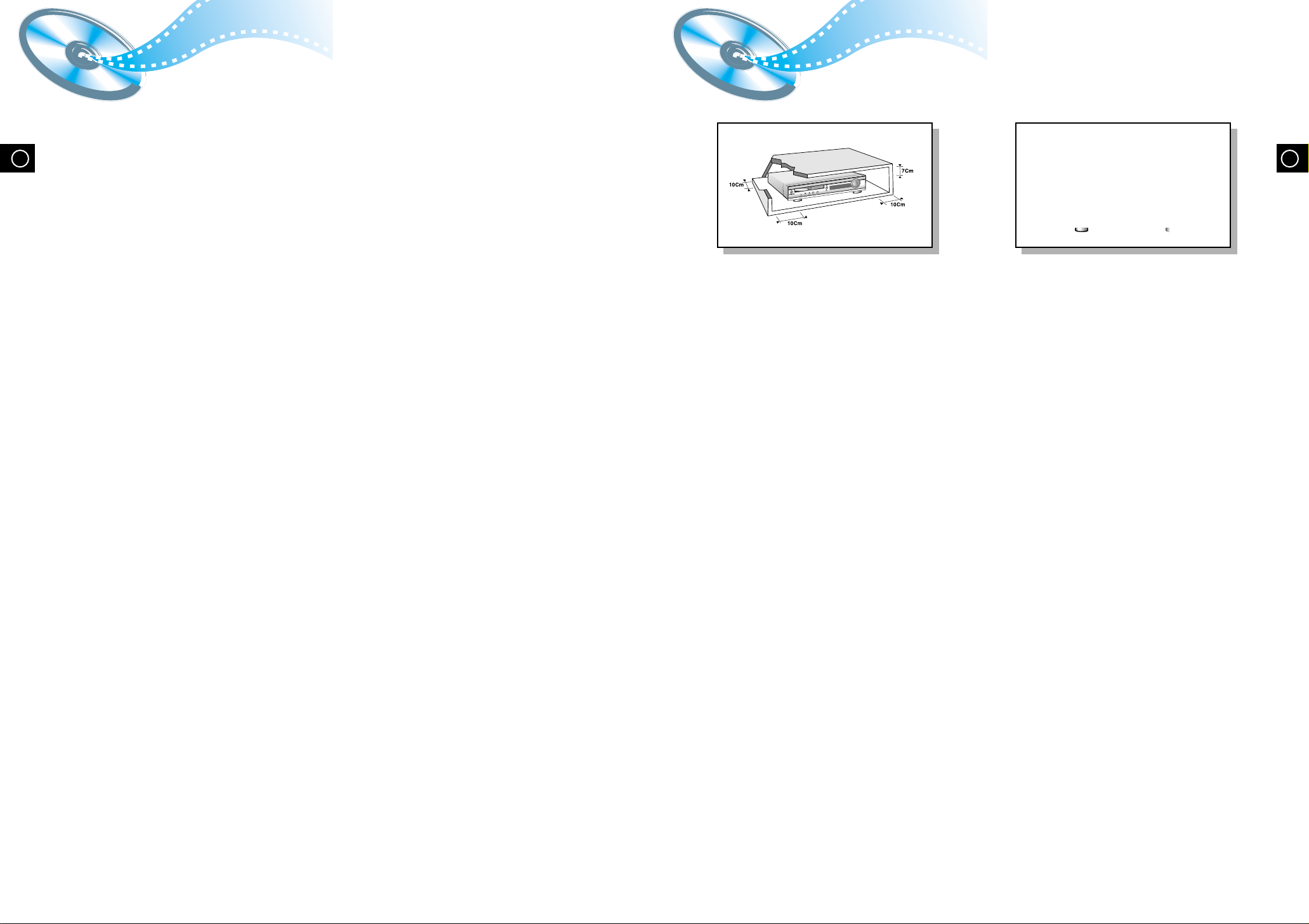
Ensure that the AC power supply in your house complies with the identification sticker located on the back of your player. Install your player
horizontally, on a suitable base (furniture), with enough space around it for ventilation (3~4inches). Make sure the ventilation slots are not
covered. Do not stack anything on top of the player. Do not place the player on amplifiers or other equipment which may become hot.
Before moving the player ensure the disc tray empty. This player is designed for continuous use. Switching off the DVD player to the stand-by
mode does not disconnect the electrical supply. In order to disconnect the player completely from the power supply, remove the main plug
from the wall outlet, especially when left unused for a long period of time.
GBGB
Protect the player from moisture(i.e. vases) , and excess heat(e.g.fireplace) or
equipment creating strong magnetic or electric fields (i.e.speakers...).
Disconnect the power cable from the AC supply if the player malfunctions.
Your player is not intended for industrial use.
Use of this product is for personal use only.
Condensation may occur if your player or disc has been stored in a cold
1
atmosphere.
If transporting the player during the winter, wait approximately 2 hours until
the unit has reached room temperature before using.
Page 3

GB
Page 4
R
Description
SURROUND
PRO LOGIC
LINEAR PCM
TITLE
TUNED
PROGRAM PBC
MHZ
KHZ
DSP
ST
LCR
LS
LFE
SRS
D I G I T A L
AUX IN
VIDEO
VIDEO OUT
ANTENN
A
S-VIDEO
SPEAKERS
SPEAKERS
AV OUT
L
R
AUX IN
VIDEO
Y/C
COMP.
VIDEO OUT
ANTENNA
S-VIDEO
AM
R-FRONT-L
R-REAR-L WOOFER CENTER
66 63
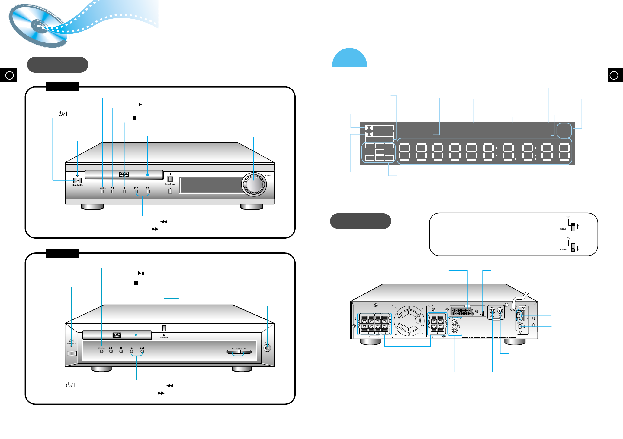
Front P anel
HT-DL70D
Power ( ) button
Standby indicator
HT-DL80D
Function button
Play/Pause ( ) button
Stop ( ) button
Open/Close button
Disc Tray
Tuning Down & Skip ( ) button
Tuning Up & Skip ( ) button
Volume control
Display
LINEAR PCM indicator
PRO LOGIC indicator
DOLBY DIGITAL
indicator
Rear Panel
TUNER indicator
TITLE indicator
SPEAKER indicator
For using the SCART cable
• If S-Video (Y/C-separation) is equipped for your TV, set Y/C-COMP.
selector of the center unit to Y/C. You can get a better picture quality
by using S-Video (Y/C-separation) setting.
• If S-Video (Y/C-separation) is not equipped for your TV,
set Y/C-COMP. selector to COMP.
STEREO indicator
PROGRAM
indicator
System Status Display
PBC
indicator
indicator
GBGB
RADIO
FREQUENCY
indicator
DSP
Function button
Standby indicator
Power ( ) button
Play/Pause ( ) button
Stop ( ) button
Disc Tray
Open/Close button
Tuning Down & Skip ( ) button
Tuning Up & Skip ( ) button
Headphone Jack
Volume button
SCART JACK
Connect to a TV with scart input jack.
5.1 Channel Speaker
Output Terminals
External Audio
Component Input
Connector
VIDEO OUT SELECT SWITCH
Use the switch to set video out
AM Antenna
Connector
FM Antenna
Connector
S-Video Output Connector
If the TV is equipped with an S-Video
input connector (S-VIDEO IN), connect it
to the player's S-Video output jack.
Video Output Connector
Connect the TV's video input jacks
(VIDEO IN) to the VIDEO OUT
connector.
65
Page 5
GBGB
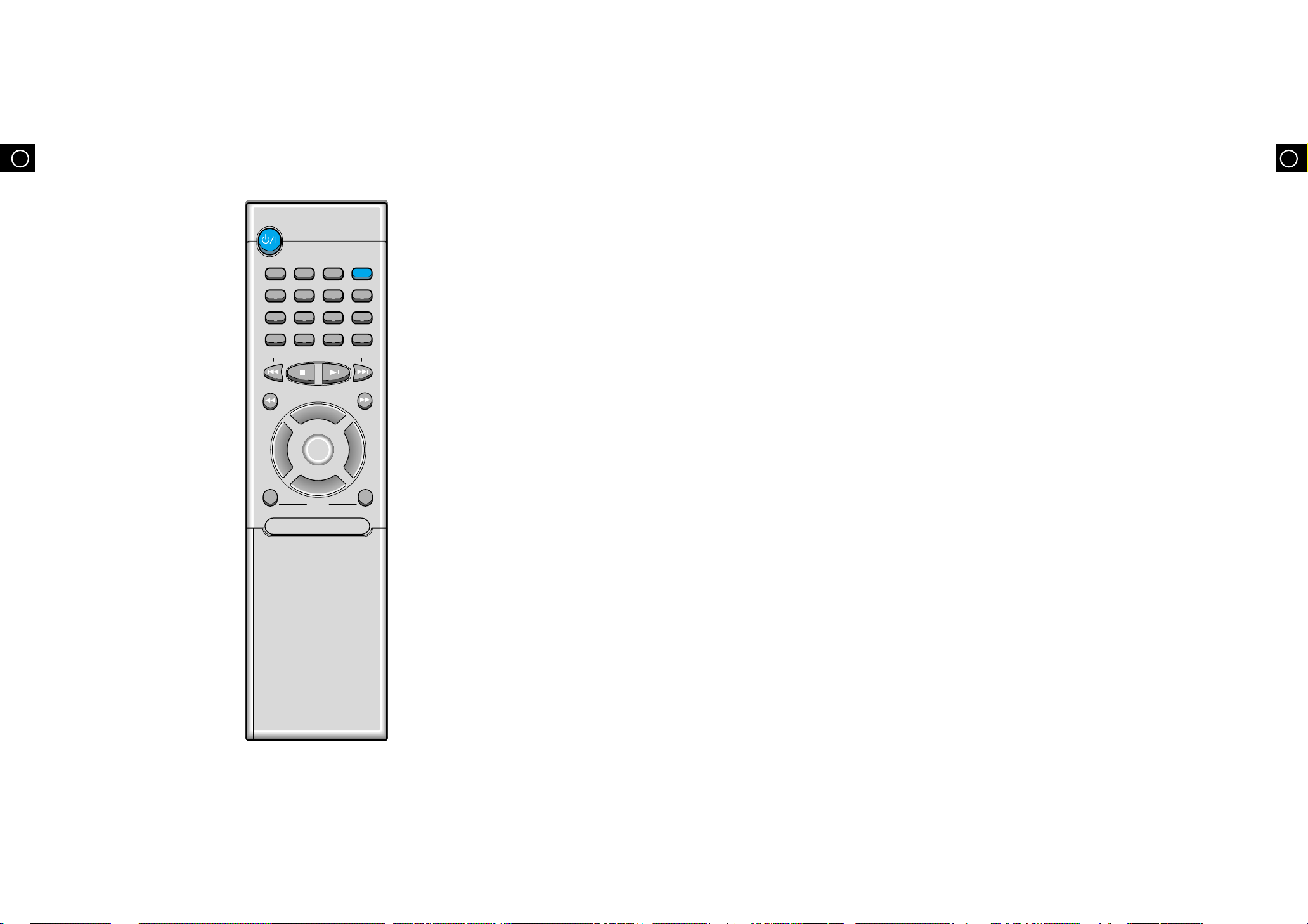
DVD
Band
A<->B
AUX Open/Clse
Display Return
DVD/CD/TUNER
Volume
DSP/EQ Power Sound Mute Sleep
Go To Zoom
Title Menu
StepRemain
SubtitleAudio
MO/ST
RepeatRepeat
7 8
Page 6

Connecting the Speakers
GBGB
9
Page 7
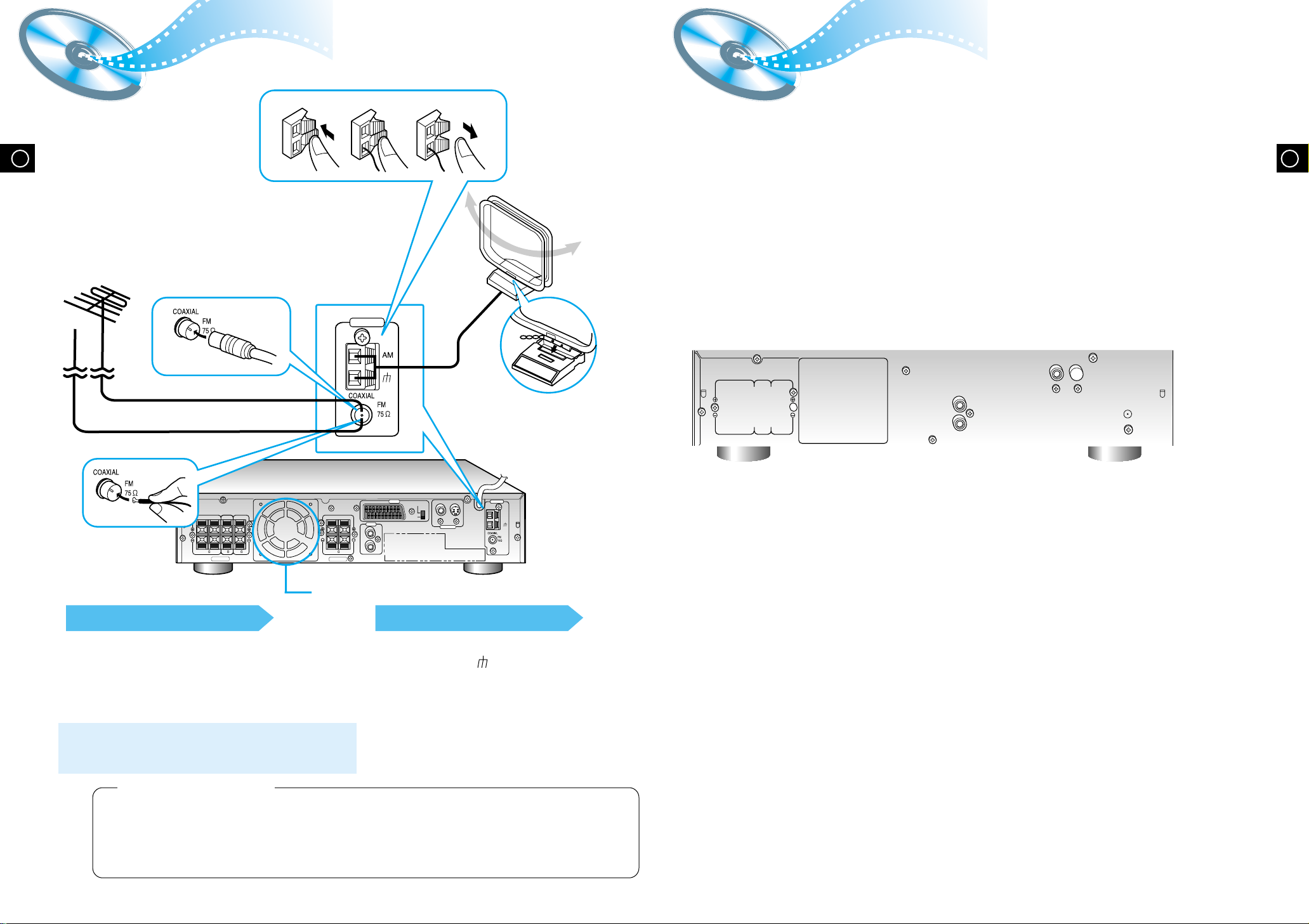
Connecting the FM and AM
AUX IN
VIDEO
VIDEO OUT
ANTENN
A
S-VIDEO
SPEAKERS
SPEAKERS
AV OUT
L
R
AUX IN
VIDEO
Y/C
COMP.
VIDEO OUT
ANTENNA
S-VIDEO
AM
R-FRONT-L
R-REAR-L WOOFER CENTER
66 63
123
ANTENNA
(
MW/LW
)
Antennas
If AM reception is
poor, connect an
outdoor AM
antenna(not
supplied).
If FM reception is poor,
connect outdoor FM antenna
(not supplied).
AM Loop Antenna
(supplied)
AUX Connections
GBGB
FM Antenna (supplied)
FM antenna connection
1. Connect the FM antenna supplied to the FM 75Ω
COAXIAL terminal.
2. Slowly move the antenna wire around until you
find a location where reception is good, then
fasten it to a wall or other rigid surface.
•
If reception is poor, connect an outdoor antenna.
Before attaching a 75Ω coaxial cable (with a standard
type connector), disconnect the supplied FM antenna.
Snap the tabs on the loop into the
slots of the base to assemble the
AM loop antenna.
AM(MW/LW) antenna connection
1. Connect the AM loop antenna supplied
to the AM and terminals.
2. If reception is poor, connect an outdoor
single vinyl-covered wire to the AM
terminal. (Keep the AM loop antenna
connected).
11
(About the cooling fan)
A cooling fan is mounted on the rear panel of the center unit to
prevent abnormal temperature inside the center unit, thus assuring
normal operation. The cooling fan automatically starts rotating to
supply external cool air to the inside of the center unit when the
internal temperature exceeds the specified limit.
For safety, observe the following carefully.
• Make sure there is good ventilation around the center unit. Poor
ventilation could overheat and damage the canter unit.
• DO NOT block the cooling fan and the ventilation openings or
holes. (If they are blocked by a newspaper or cloth, etc., the heat
may not be able to escape.)
12
Page 8

The “WAIT” message that appears on the display for about seven to eight seconds when
•
turning on the power or selecting a DVD function indicates a stabilization period for
optimizing the condition of your DVD player. While the message is being displayed, other
buttons remain inactive.
When the power is not turned on, press down the Stop ( ) button on the main unit for
•
over 5 seconds.
The product will be initialized to its optimum state.
Certain operational features such as the Speaker mode, Test tone, Volume, etc.
•
will not be displayed on the TV screen.
GBGB
Page 9

DVD Playback
Display
Display
Display
Display
V I D E O
1/2 1/8 00:00:00
TC
V I D E O
ENG ENG OFF1/3 1/1
Mute
V I D E O
GB
1
Press the Open/Close( ) button
to open the disc tray.
The button is located on the Front Panel
•
of the player (not on the remote).
2
Insert a disc.
Place a disc gently into the tray with the
•
disc’s label facing up.
3
Press the Open/Close( ) button
again to close the disc tray.
Playback starts automatically.
•
Using the On-Screen Display
Press the Display button on the remote.
DVD indicator
SUBTITLE LANGUAGE
indicator
The On-Screen Display disappears.
TITLE indicator
CHAPTER indicator
AUDIO LANGUAGE
indicator
GB
TITLE ELAPSED
indicator
ANGLE indicator
REPEAT indicator
DISC TYPE indicator
Pausing Playback
Press the Play/Pause ( ) button during
playback.
To resume, press the Play/Pause ( )
•
button again.
Depending on the disc, the initial disc
•
information screen may look different
from disc to disc.
When playing a DVD containing MPEG
•
format, video may not be reproduced
correctly and you may get picture
distortion.
15
Stopping Playback
Press the Stop ( ) button during playback.
During playback, when the Stop ( )button is pressed,
•
the position is stored in the memory, and STOP is
shown on the display.
When the Play/Pause ( ) button or Return button is
pressed subsequently, playback resumes from the
position at which it was stopped.
If the Stop ( ) button is pressed a second time, the
•
‘resume play’ memory function is canceled, and
STOP is shown on the display. When the Play/Pause
( )button is pressed, playback starts from the
beginning.
What is a Title?
A movie contained in a
DVD disc.
What is a Chapter?
Each Title on a DVD
disc is divided into
several smaller sections
called "chapters".
Turning the sound off temporarily?
Press the Mute button during playback.
This operation may be useful when you need
•
to greet guests or answer the telephone.
If the player is left for more than 3 minutes
in pause mode, it will stop.
16
Page 10

Page 11

Using Disc Menu/Title
GB
20
Page 12

GB22GBGB
Page 13

Selecting the Audio Language/Subtitle Language
V I D E O
OFF 1/1
ENGENG
SPA
FRE
1/3
2/3
3/3
V I D E O
OFF1/1 1/1
SPA
ENG
FRE
OFF
ENG
1/3
2/3
3/3
Various DVD Functions
Selecting the Audio Language
Depending on the number of languages recorded on a DVD disc, a
•
different audio language (ENGLISH, SPANISH, FRENCH, etc.) is
selected each time the button is pressed.
Depending on the disc, DTS or DIGITAL PRO LOGIC can be
•
selected.
Selecting the Subtitle Language
To enlarge an image
Images can be enlarged 2x and 4x.
•
During DVD playback, press the Zoom button
•
to zoom in 2X/4X/normal, in that order.
Press
•
portion you want to watch.
/ / ▲ / ▼ to move the enlarged
Selecting the desired Screen Angle
This function only works with discs on which multiple angles have been recorded.
•
During playback, press the Angle button to select the desired angle in 1/3, 2/3, 3/3,
•
normal, in that order.
DOLBY
D I G I T A L
OFF 1/3
2/3
Depending on the number of languages recorded on a DVD disc, a
•
different subtitle language (ENGLISH, SPANISH, FRENCH etc.) is
selected each time the button is pressed.
To make the subtitles disappear, select "OFF".
•
3/3
2423
Page 14

GB
MP3 Playback
This system has a built-in MP3 decoder.
You can play back MP3 tracks (files)recorded on CD-Rs, CD-RWs, and CD-ROMs.
Starting Playback
It is recommended you turn on your
•
TV when playing back an MP3 disc.
1
Press the Open/Close( ) button
to load a disc.
2
Press the Play/Pause( ) button.
After detecting the disc, playback starts.
•
The on-screen bar and the contents
•
recorded on the MP3 disc will be shown
on the TV if it is turned on.
GB
25
26
Page 15

4:3 LB
OFF
RATING LEVEL
BITSTREAM
OUTPUT
DIGITAL
TV SCREEN
: Move Setup : Exit
LANGUAGES SYSTEM
4:3 LB
BITSTREAM
OUTPUT
DIGITAL
TV SCREEN
RATING LEVEL
: Move Setup : Exit
LANGUAGES SYSTEM
OUTPUT
DIGITAL
TV SCREEN
RATING LEVEL
: Move Setup : Exit
LANGUAGES SYSTEM
4:3 LB
You can use the DVD player's Setup function to select the TV screen ratio,
rating limit, or digital output mode.
GBGB
TV SCREEN(TV SCREEN RATIO)
Select when you want to watch a 16:9 screen ratio DVD movie on a TV with a 4:3 ratio screen.
4:3LB
4:3PS
16:9
If the movie is recorded in 4:3 ratio, you cannot view the full 16:9 picture with the above
•
functions.
RATING LEVEL
The Rating Level function works in conjunction with DVDs which have been assigned
a rating, to help control the type of DVD that your family watches.
LANGUAGES SYSTEM
TV SCREEN
RATING LEVEL
DIGITAL
4:3 LB
OFF
BITSTREAM
OUTPUT
: Move Setup : Exit
1. Select RATING LEVEL, then press the
Enter button.
2. Use the number(0~9) buttons to input
a 4-digit password.
•
You can see the full 16:9 picture, but black bars will appear at the
top and bottom of the screen.
You can only view the central portion of the 16:9 screen.
You can view in widescreen, but the top and bottom of the picture
will be cut off.
The player’s password is set to "7890" by
default.
When the rating level
password has been forgotten
While the player is in the stop
mode, hold the Stop ( ) button
down on the main unit for more than
5 seconds.
"INITIAL" appears on the display and
•
all default settings will return to
Factory Preset.
Press the Power button.
•
27
3. Use the Up/Down (▲ / ▼ ) button to select either RATING LEVEL or
NEW PASSWORD, and then press the Enter button.
There are up to 8 rating levels on a disc.
•
If LEVEL 6 is selected, a disc which contains rating LEVEL 7 and above cannot
•
be played.
If you select NEW PASSWORD, the screen changes and enables you to enter
•
the new password.
28
Page 16

Setting up the Language Features
Setup
Setup
D.R.C
TITLE
TUNED
PROGRAM PBC
MHZ
KHZ
SURROUND DSP
ST
PRO LOGIC
LINEAR PCM
LCR
LS
LFE
SRS
D I G I T A L
Using the DVD player's Setup function, you can customize the Menu
Language, Subtitle Language, and Disc Menu Language.
To set up the language feature
12
Press the Setup button from the stop mode.
LANGUAGES
OSD LANGUAGE
AUDIO
SUBTITLE
MENU LANGUAGE
: Move Setup : Exit
SYSTEM
ENGLISH
CHINESE
CHINESE
CHINESE
Press the Up/Down ( ▲ / ▼ ) button to select
the desired item.
SYSTEM LANGUAGES
OSD LANGUAGE
AUDIO
SUBTITLE
MENU LANGUAGE
: Move Setup : Exit
ENGLISH
CHINESE
CHINESE
CHI NESE
Activating Dynamic Range Compression
Activating Dynamic Range Compression
You can enjoy a powerful sound even at a low volume level by
compressing the dynamic range (difference between the maximum and
minimum sounds).
om the remote control ONLY:
Fr
Press the D.R.C button.
Each time you press the button,the dynamic range
•
compression mode alternates between on and off. Select
“D.R.C.ON ” while watching the DVD at night.
(You can obtain a powerful sound at a low volume.)
This function takes effect only when Dolby Digital or DTS
•
Digital Surround is activated.
GBGB
34
Press the Enter button or Right ( ) button.
LANGUAGES
OSD LANGUAGE
AUDIO
SUBTITLE
MENU LANGUAGE
: Move Setup : Exit
SYSTEM
ENGLISH
CHINESE
CHINESE
ENGLISH
▲
OSD LANGUAGE
AUDIO
SUBTITLE
MENU LANGUAGE
(PLAYER MENU LANGUAGE)
(AUDIO LANGUAGE)
(SUBTITLE LANGUAGE)
(DISC MENU LANGUAGE)
Press the Up/Down ( ▲ / ▼ ) button to select
the desired language and then press the Enter
button.
LANGUAGES
OSD LANGUAGE
AUDIO
SUBTITLE
MENU LANGUAGE
: Move Setup : Exit
SYSTEM
ENGLISH
ENGLISH
CHINESE
CHINESE
CHINESE
FRENCH
GERMAN
JAPANESE
To End the Language Features Setup
Press the Setup button again.
•
29
30
Page 17

Speaker Setup
SPK Mode
DIGITAL
L
LS RS
C
LFT
R
F SP SMALL
C SP SMALL
R SP SMALL
SW SP USE
DIGITAL
L
LS RS
C
LFT
R
DIGITAL
L
LS RS
C
LFT
R
DIGITAL
L
LS RS
C
LFT
R
DIGITAL
L
LS RS
C
LFT
R
RMS
DIGITAL
L
LS RS
C
LFT
R
DEL
GB
Setting up Speaker Mode and Delay Time
Press the SPK Mode button.
Each time the button is pressed, a different mode selection is
•
displayed on the front panel display as shown below.
S
p
e
a
k
e
r
M
o
d
e
Delay
Time
Front speaker: Small
Center speaker: Small
Rear speaker: Small
Subwoofer: Use
Setting up Delay Time from 00~05ms
Center Speaker Delay Time
Setting up Delay Time from 00~15ms
Rear Speaker Delay Time
To set the delay time
When 5.1 Channel Surround Sound is played, you
•
can enjoy the best sound if the distance between
you and each speaker is the same. You can set
Delay Time in the Center/Rear Speaker to
customize the sound to the acoustics of your room.
Setting Center Speaker
•
If the distance of Dc is equal to or longer than the
distance of Df in the figure, set the mode as 0ms.
Otherwise, change the setting according to the
table on the table.
Setting Rear Speakers
•
If the distance of Df is equal to the distance of Ds
in the figure, set the mode as 0ms.
Otherwise, change the setting according to the
table.
Speaker Setting Methods
R
(A)=Df-Dc
Distance of (A)
50
100
150
200
(B)=Df-Ds
Distance of (B)
200
400
600
Dc: Distance from center speaker to
listening position
Df: Distance from front speakers to
listening position
Ds: Distance from rear speakers to
listening position
Value
1.3ms
2.6ms
3.9ms
5.3ms
Value
5.3ms
10.6ms
15.9ms
Ideal Center Speaker Position
Dc
Ideal Rear Speaker Position
Arrange all speakers within a circle
as shown in the figure.
Df
Ds
Front Speakers
Set the front speakers so that their tweeters (high-range) are
aligned at about ear level and at a horizontal angle of 45° to the
prime listening position.
Center Speaker
GB
•
•
The display changes depending on the current audio output
•
mode (DSP, PRO LOGIC, 3-STEREO, STEREO, etc.).
When in the speaker mode, the center and rear speakers and
•
the subwoofer cannot be selected.
31
SMALL: When this setting is selected, low frequencies of below 200 Hz are assigned to
the subwoofer only.
USE: Select when using speakers.
Ideally the center speaker should be positioned with its top
surface flush with the front speakers. However, you may place
the speaker either on top or near the bottom of your TV set.
Rear Speakers
Set the rear speakers further back, parallel to the walls,
at 60 to 90 centimeters (2 to 3 feet) above prime listening
position ear level.
If the space behind the listening position is insufficient
(i.e., too close to the wall), place the rear speakers facing
each other on either side.
Subwoofer Speaker
Place the subwoofer at any convenient location within
the vicinity of the listening position.
32
Page 18

GBGB
3433
Page 19

GBGB
3635
Page 20

Listening to the Radio
Audio
MO/ST
You can listen to the chosen band (FM, MW or LW broadcast stations) by using either
the automatic tuning or manual tuning operation.
1
2
Presetting stations
You can store up to:
15 FM stations
8 MW stations
7 LW stations
Example: Presetting FM 89.1 in the memory
• FM Frequency Modulation
• AM(MW) Medium Wave
• LW Long Wave
GBGB
Remote
Control
Unit
Main
Unit
Press the Tuner(Band)
button.
The selection toggles back
•
and forth between "FM" "MW"
and "LW" each time the
Tuner(Band) button is
pressed.
1
Press the Function button to
select the desired band (FM,
MW or LW).
Select a broadcast station.
Auto Station 1
Auto Station 2
Manual Station
Auto Station 1
Auto Station 2
When the button is pressed, a preset
broadcast station is selected.
Hold in the button. Automatic searching
begins, and then stops when a station is tuned in.
Press the button to tune to the chosen
station. The frequency changes incrementally in either
direction each time the corresponding button is pressed.
Select a broadcast station.
Press the Stop ( ) button to select the PRESET
mode. Then press the button to select a
station stored in the preset. See the instructions on the
next page to preset stations.
Press the Stop ( ) button to select the MANUAL
mode on the front panel. Then hold in the
button to make the unit begin automatically searching for
broadcast stations.
2
1
Press the Tuner(Band) button
and select the FM band.
The selection toggles back and forth between “ ”
•
each time the Tuner(Band) button is pressed.
LR
Select MANUAL by pressing
the Stop ( ) button on the
main unit.
MH
Z
LR
2
456
Press the Program button on
the remote control, FM1 will
flash. If you want to save 89.1
to FM1, press Program again.
PROGRAM
LR
If you want to save 89.1 to another
preset location(FM2~FM15), press
Program to save it to that location.
MH
Z
LR
LR
▲
▲
or , then press
▲
▲
PROGRAM
MH
Z
MH
Z
3
▲
Use the and
button to tune to 89.1
LR
To preset other stations,
follow steps 1~4 again.
▲
▲
▲
MH
Z
Manual Station
Press the Stop ( ) button to select the MANUAL mode
on the front panel. Press the button to tune
to the desired station. The frequency changes
incrementally in either direction each time the
corresponding button is pressed.
To store other Channels
Follow steps 3~5 again.
•
To tune in a preset station
See the previous page.
•
To Listen in Mono/Stereo
Press the MO/ST button. (FM only)
The selection toggles back and forth between “STEREO” and “MONO”
•
each time the MO/ST button is pressed.
In a poor reception areas, select Mono mode for a clear, interference-free
•
broadcast.
37 38
Page 21

About RDS broadcasting
Using the RDS (Radio Data System) to receive FM stations
RDS allows FM stations to send an additional signal along with their regular program signals.
For example, the stations send their station names, as well as information about what type of program
they broadcast, such as sports or music,etc.
When tuned to an FM station which provides the RDS service, the RDS indicator lights up on the display.
Description on RDS function
•
1. PTY (Program Type) : Displays the type of programme currently being broadcast
2.
PS NAME (Program Service Name) : Indicates the name of broadcasting station and is composed of 8 characters.
3. RT (Radio Text) :
4. CT (Clock Time) : Decodes the real time clock from the FM frequency.
5. TA (Traffic Announcement) :
RDS is not available for MW/LW broadcasts.
•
RDS may not operate correctly if the station tuned is not transmitting RDS
•
signal properly or if the signal strength is weak.
Decodes the text broadcast by a station (if any) and is composed of maximum 64 characters.
Some stations may not transmit PTY, RT or CT information therefore this may not be displayed in all cases.
•
When this symbol flashes it shows that the traffic announcement is in progress.
What information can RDS signals provide?
You can see the RDS signals the station sends on the display.
GBGB
TO show the RDS signals
Press RDS DISPLAY while listening to an FM ststion.
Each time you press the button, the display change to show you the following information:
PS (Program Service) : While searching,"PS"appears and then the station names will be
displayed."NO PS" appears if no signal is sent.
PTY (Program Type) : while searching,"PTY" appears and then the type of the broadcast program will
be displayed. "NO PTY"appears if no signal is sent.
RT(RadioText) : while searching,"RT"appears and then text messages the station sends will be
displayed. "NO RT"appears if no signal is sent.
Frequency : station frequency (non-RDS service)
About characters shown in the display
When the display shows PS,PTY,or RT signals,the following haracters are used.
The display window cannot differentiate upper case and lower case lrtters and always uses upper
•
case letters.
The display window cannot show accented letters, “A,” for instance, may stans for accented “A’s” like
•
“À, Â, Ä, Á, Åand Ã.”
If searching finishes at once,“PS”,“PTY”,and “RT” will not appear on the display.
39
40
Page 22

GB GB42GBGB
41
Page 23

Problem Check
• The disc revolves but no
picture appears.
• Picture shows interference
and quality is poor.
Remote control unit does
not operate.
Audio or subtitle language
does not operate.
Is the TV power turned on?
•
Are the video cables properly connected?
•
Is it the player in PAUSE mode?
•
Is there any dirt on the disc, or is the disc damaged?
•
It may not be possible to play some DVD discs due to poor
•
manufacture.
When a dark scene changes to a bright scene during playback, the
•
screen may flicker vertically. Some disturbance is normal.
Is the remote control being used within the appropriate distance
•
and angle of operation for the unit?
• Are there any obstacles between the remote control unit and the
remote control sensor?
Are the batteries dead? Is it time to replace the batteries with new
•
ones?
The audio or subtitle language features does not operate with
•
DVDs that do not include multiple audio or subtitle languages.
Cautions on Handling and Storing Discs
Small scratches on the disc may reduce sound and picture quality or cause breaks
in playback. Be especially careful not to scratch discs when handling them.
Handling and Storing Discs
When you get fingerprints or dirt on the
disc, clean it with a mild detergent diluted
in water and wipe with a soft cloth.
When cleaning, wipe gently from the inside to the
•
outside of the disc.
Condensation may form if warm air comes into
contact with cold parts inside the player. When
condensation forms inside the player, the
player may not operate correctly. If this occurs,
remove the disc and let the player stand for 1
or 2 hours with the power on.
The Menu button is
pressed but the Menu
screen does not appear.
The screen ratio cannot
be changed.
The desired radio station
cannot be tuned in.
The system is
malfunctioning (the
system does not work or
no sound).
Is the remote control being used within the appropriate distance
•
and angle of operation for the unit?
Are the batteries dead?
•
Does the disc have a Menu?
•
You can play 16:9 wide DVDs in 16:9 WIDE mode or 4:3 LETTER
•
BOX mode or 4:3 PAN-SCAN mode; but 4:3 encoded DVDs only
show in 4:3 ratio. Refer to the DVD disc jacket and then select the
appropriate function.
Is the antenna installed properly?
•
When the antenna's input signal is weak, install an external FM
•
antenna in an area with good reception quality.
While the player is in the stop mode, hold the Stop ( ) button
•
down on the main unit for over 5 seconds."INITIAL" appears on the
display and all settings will return to the Factory Preset condition.
The RESET function erases all settings; do not use this
function unless necessary.
Disc Storage
Do not keep in direct
sunlight
Do not allow the discs to become contaminated
•
with dirt.
Do not load cracked discs or discs that are
•
scratched.
Keep in a cool
ventilated area
Keep in a clean
Protection jacket.
Store vertically.
4443
Page 24

GBGB
4645
Page 25

GB
GB
47
48
 Loading...