

Samsung HT-AS601T, HT-AS601B User Manual
ELECTRONICS
Instruction Manual
Digital Surround
AV Receiver System
HT-AS601
AH-01751K
GB
2
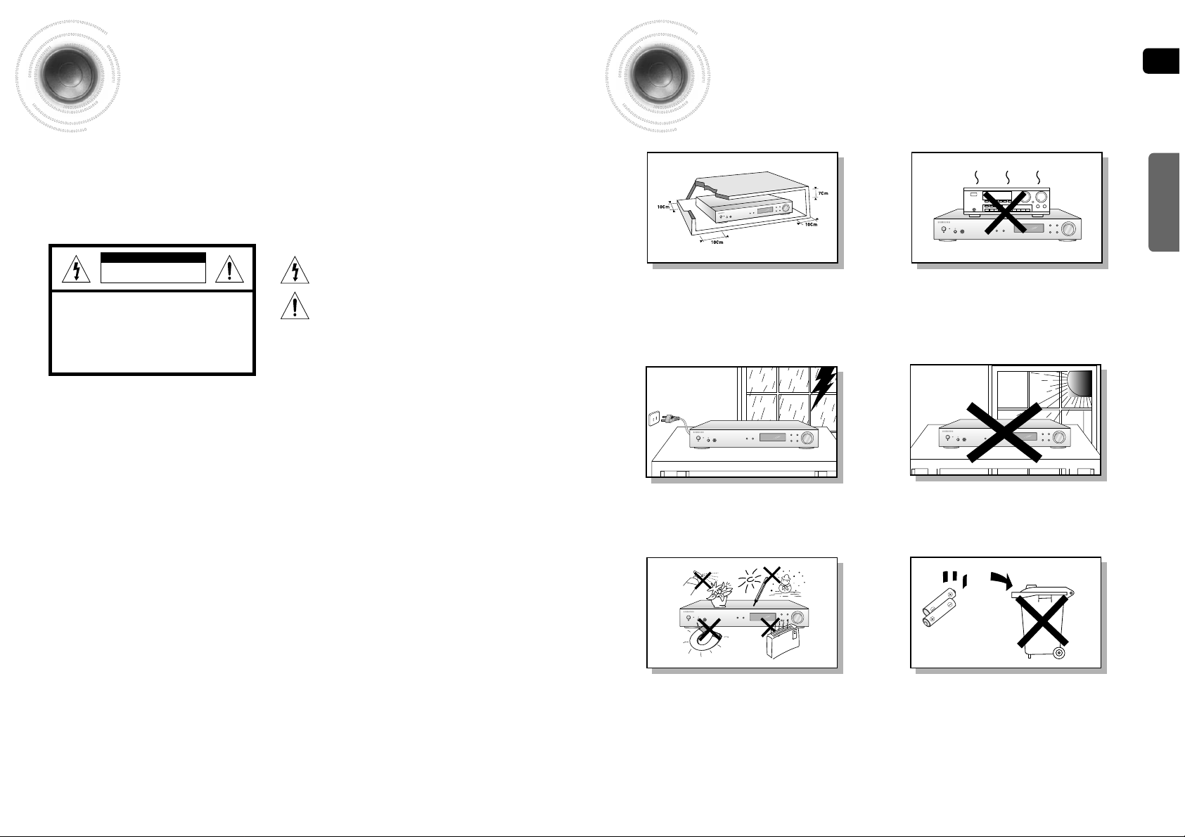
Precautions
Ensure that the AC power supply in your house complies with the identification sticker located on the back of your player. Install
your player horizontally, on a suitable base (furniture), with enough space around it for ventilation (3~4inches). Make sure the
ventilation slots are not covered. Do not stack anything on top of the player. Do not place the player on amplifiers or other
equipment which may become hot. Before moving the player, ensure the disc tray is empty. This player is designed for
continuous use. Switching off the DVD player to the stand-by mode does not disconnect the electrical supply. In order to
disconnect the player completely from the power supply, remove the main plug from the wall outlet, especially when left unused
for a long period of time.
Protect the player from moisture(i.e. vases) , and excess
heat(e.g.fireplace) or equipment creating strong magnetic or
electric fields (i.e.speakers...). Disconnect the power cable from
the AC supply if the player malfunctions. Your player is not
intended for industrial use.
Use of this product is for personal use only.
Condensation may occur if your player or disc have been
stored in cold temperatures.
If transporting the player during the winter, wait approximately 2
hours until the unit has reached room temperature before using.
During thunderstorms, disconnect AC main plug from
the wall outlet.
Voltage peaks due to lightning could damage the unit.
Do not expose the unit to direct sunlight or other heat
sources.
This could lead to overheating and malfunction of the
unit.
The battery used with this product contain chemicals
that are harmful to the environment.
Do not dispose of batteries in the general household
trash.
PREP ARATION
1
Safety Warnings
This symbol indicates that dangerous voltage which
can cause electric shock is present inside this unit.
This symbol alerts you to important operating and
maintenance instructions accompanying the unit.
WARNING: To reduce the risk of fire or electric shock, do not
expose this appliance to rain or moisture.
CAUTION: TO PREVENT ELECTRIC SHOCK, MATCH
WIDE BLADE OF PLUG TO WIDE SLOT, FULLY
INSERT.
RISK OF ELECTRIC SHOCK.
DO NOT OPEN
CAUTION:
TO REDUCE THE RISK OF ELECTRIC SHOCK, DO NOT
REMOVE REAR COVER. NO USER SERVICEABLE
PARTS INSIDE. REFER SERVICING TO QUALIFIED
SERVICE PERSONNEL.
CLASS 1 LASER PRODUCT
This Compact Disc player is classified
as a CLASS 1 LASER product.
CAUTION
Contents
4
PREPARATION
Safety Warnings..............................................................................................................1
Precautions......................................................................................................................2
Features ..........................................................................................................................3
Description ......................................................................................................................5
CONNECTIONS
Connecting the Speakers................................................................................................9
Connecting External Components ..................................................................................11
Connecting the FM and AM Antennas.............................................................................14
OPERATION
Before Using the AV Receiver.........................................................................................15
Selecting External Component Input ..............................................................................16
Setting the Speaker Mode...............................................................................................17
Setting the Speaker Listening Distance...........................................................................19
Setting DRC (Dynamic Range Compression) .................................................................21
Test Tone ........................................................................................................................22
Setting Speaker Level .....................................................................................................25
Dolby Pro Logic llx Mode................................................................................................27
Dolby Pro Logic llx Effect................................................................................................29
NEO:6 Mode....................................................................................................................31
SFE Mode........................................................................................................................33
EX/ES Mode....................................................................................................................35
Stereo Mode....................................................................................................................37
RADIO OPERATION
Listening to Radio ...........................................................................................................39
Presetting Radio Stations ...............................................................................................40
MISCELLANEOUS
Convenient Functions .....................................................................................................41
Operating TV with Remote Control..................................................................................43
Operating your VCR (DVD) with Remote Control............................................................45
Before Calling for Service................................................................................................47
Specifications ..................................................................................................................49
PREP ARATION
Dolby Pro Logic ll x
Dolby Pro Logic ll x is a new type of multiple channel audio signal decoding method that
improves upon existing Dolby Pro Logic.
DTS 96/24
DTS is the surround format implementing 5.1 channel multi channel sounds at 96KHz/24bit
without losing the image quality of DVD. In addition, it can reproduce the matrix 6.1 of DTS
96/24 decoder signal.
DOLBY DIGITAL EX
Adds a rear center channel for more spacious sound compared to regular 5.1 channel Dolby
Digital.
Features
3
DTS (Digital Theater Systems)
DTS play backs 5.1 channel sound with less compression than Dolby Digital for richer
sound.
DTS-ES
DTS-ES is the surround format implementing 6.1 channels while preserving compatibility to
existing DTS Digital Sound formats.
DTS
Reproduces digital PCM or analog stereo over 6.1 channels using a high precision DTS
digital matrix.
GB
GB
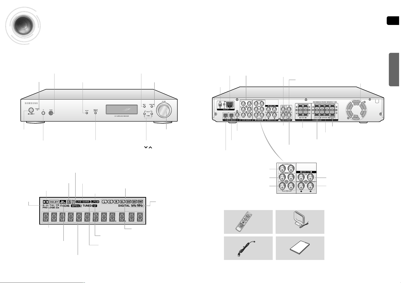
6
COOLING FAN
VCR/SAT VIDEO INPUT
JACK
5.1 CH ANALOG
AUDIO JACKS
AM ANTENNA
JACK
FM ANTENNA
JACK
DVD OPTICAL DIGITAL
AUDIO INPUT JACK
SAT(SETTOP BOX) OPTICAL
DIGITAL AUDIO INPUT JACK
CD COAXIAL DIGITAL
AUDIO INPUT JACK
VCR VIDEO OUTPUT
JACK
FRONT SPEAKER
TERMINALS
SURROUND BACK SPEAKER TERMINALS
[
Rear Panel
]
CD AUDIO INPUT JACKS
DVD AUDIO INPUT JACKS
VCR/SAT AUDIO INPUT JACKS
VCR AUDIO OUTPUT JACKS
SUBWOOFER OUTPUT JACKS 1, 2
PREP ARATION
DVD VIDEO INPUT
JACK
CENTER SPEAKER TERMINALS
SURROUND SPEAKER TERMINALS
Description
[
Front Panel
]
[
Display
]
POWER button VOLUME CONTROL
REMOTE CONTROL Sensor ANALOG / DIGITAL BUTTON SELECTION button
TUNER ( ) button
POWER STANDBY Indicator SETUP button SURROUND button
HEADPHONE Jack
INPUT button
5
SPEAKER INDICATOR
DOLBY PRO
LOGIC II
X
INDICATOR
RADIO BROADCASTING
RECEIVING INDICATOR
RADIO STEREO INDICATOR
DIGITAL INDICATOR
RADIO FREQUENCY
INDICATOR
DTS ES 96/24
INDICATOR
LIVE SURROUND
INDICATOR
L.PCM
INDICATOR
NEO:6
INDICATOR
DOLBY DIGITAL
EX INDICATOR
MPEG2
INDICATOR
,
FRONT DISPLAY
DOLBY
INDICATOR
MONITOR VIDEO
OUTPUT JACK
Accessories
√√
œœ
Remote Control
FM Antenna User’s Manual
AM Antenna
GB
8
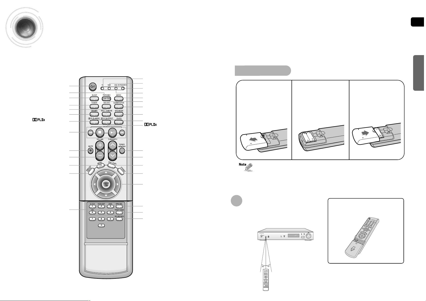
To open the remote control cover,
push the top of the cover, then slide
downward.
Insert Remote Batteries
The remote control can be used up to approximately 23
feet/7 meters in a straight line. It can also be operated at
a horizontal angle of up to 30° from the remote control
sensor.
Range of Operation of the Remote Control
Remove the battery
cover on the back of
the remote by
pressing down and
sliding the cover in
the direction of the
arrow.
1
Insert two 1.5V AAA
batteries, paying
attention to the correct
polarities (+ and –).
2
Replace the battery
cover.
3
Follow these precautions to avoid leaking or cracking batteries:
•
Place batteries in the remote control so they match the polarity:(+) to (+)and (–)to (–).
•
Use the correct type of batteries.Batteries that look similar may differ in voltage.
•
Always replace both batteries at the same time.
•
Do not expose batteries to heat or flame.
PREP ARATION
Description
VOLUME CONTROL button
MUTE button
MENU button
ANALOG/DIGITAL button
POWER button
TV VIDEO, FUNCTION button
SLEEP button
TUNER button
NEO : 6 button
EXTERNAL DEVICE PLAYBACK button
DIMMER button
MODE button
Direct Function Select button
TV Indicator
VCR Indicator
AV RECEIVER Indicator
DVD Indicator
MODE button
MO/ST button
SUBWOOFER button
SFE MODE button
EX/ES button
EFFECT button
STEREO button
MOVE/SELECT button
TUNER MEMORY button
TUNING/CHANNEL button
SPEAKER LEVEL button
TEST TONE button
SPEAKER SETUP button
SPEAKER DISTANCE button
[
Remote Control
]
7
GB
10
CONNECTIONS
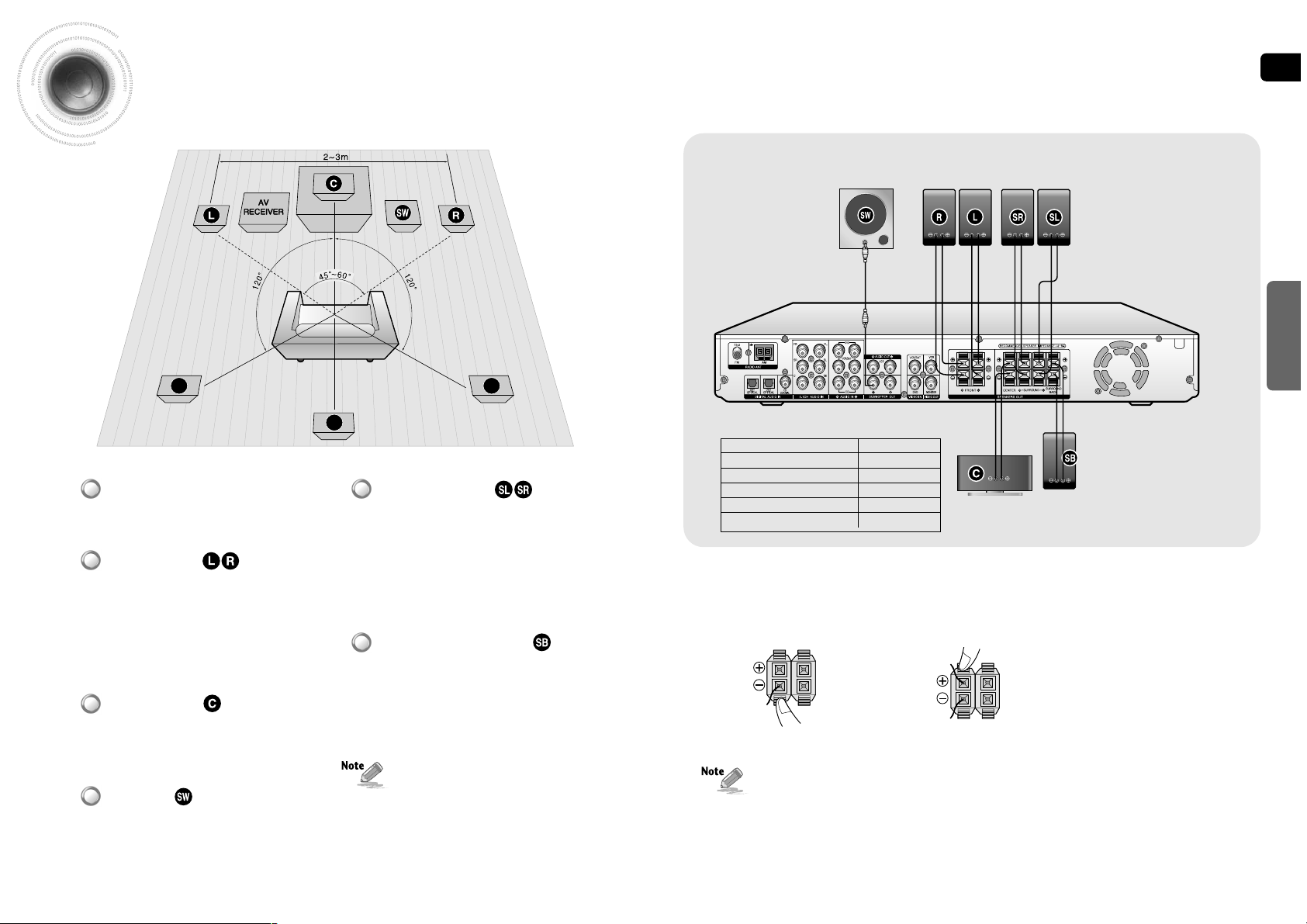
•
Never touch speaker terminals while the power is on.
Doing so could result in electric shock.
•
Make sure the polarities (+ and -) are correct.
MAIN UNIT AV-R601
FRONT SPEAKER PS-AF601
CENTER SPEAKER PS-AC601
SURROUND SPEAKER PS-AR601
SURROUND BACK SPEAKER
PS-AB601
ACTIVE SUBWOOFER PS-AW601
SYSTEM MODEL NAME : HT-AS601
√ Connecting Speaker Wire
ACTIVE SUBWOOFER
(BUILT-IN POWER AMPLIFIER)
PS-AW601
FRONT (R)
PS-AF601
FRONT (L)
PS-AF601
SURROUND(R)
PS-AR601
SURROUND (L)
PS-AR601
MAIN UNIT
AV-R601
CENTER
PS-AC601
SURROUND
BACK
PS-AB601
1
Press the tab of the
speaker connector.
2
Insert the black wire into the black(-)
terminal and the gray wire into the
gray(+) terminal.
Connecting the Speakers
Before moving or installing the product, be sure to turn off the power and disconnect the power cord.
•
Place these speakers behind your listening position.
•
If there isn't enough room, place these speakers so they
face each other.
•
Place them about 60 to 90cm (2 to 3feet) above your ear,
facing slightly downward.
❈ Unlike the front and center speakers, the surround
speakers are used to handle mainly sound effects and
sound will not come from them all the time.
Surround Speakers
•
Place it so it faces forward towards the back of the listener.
•
Place the surround center speaker about 70 cm to 1 m
(2.3~3.3feet) above rear speakers, facing slightly
downwards.
Surround Center Speaker
SL SR
SB
•
Place these speakers in front of your listening
position, facing inwards (about 45°) toward you.
•
Place the speakers so that their tweeters will be at
the same height as your ear.
•
Align the front face of the front speakers with the
front face of the center speaker or place them
slightly in front of the center speakers.
Front Speakers
•
It is best to install it at the same height as the front
speakers.
•
You can also install it directly over or under the TV.
Center Speaker
•
Place AV Receiver on a dedicated stand or rack.
Position of A V Receiver
•
The position of the subwoofer is not so critical.
Place it anywhere you like.
Subwoofer
•
When you place the speaker on the wall, make sure to
fasten it tightly so that it may not fall off.
9

GB
SA T(Settop Box)
VCR
TV
•
Since Analog Audio In and Video In jack of the main
unit are used for both SAT and VCR, you cannot
connect 2 devices at the same time.
•
If the external component has only one Audio Output
jack, connect it to either the right or left Audio Input jack
of the main unit.
•
Connect the audio cable's red plug to the red jack and
white cable to the white jack.
12
CONNECTIONS
Connecting External Components
DVD Player
•
Disconnect the power plug from the outlet if you do not use this unit for long period of time.
Before moving or installing the product, be sure to turn off the power and disconnect the power cord.
Connecting Video Component
11
Video Projector

GB
14
1. Connect the FM antenna supplied to the FM
75ΩCOAXIAL terminal as a temporary measure.
2. Slowly move the antenna wire around until you find
a location where reception is good, then fasten it to
a wall or other rigid surface.
1. Connect the AM loop antenna supplied to the AM
and terminals.
2. If reception is poor, connect an outdoor single vinyl-
covered wire to the AM terminal.
(Keep the AM loop antenna connected).
The cooling fan dissipates the heat generated inside the unit so that the unit can
be operated normally. The cooling fan is activated automatically to supply cool air
to the unit.
Please observe the following cautions for your safety .
•
Make sure the unit is well-ventilated. If the unit has poor ventilation, the temperature inside the
unit could rise and may damage it.
•
Do not obstruct the cooling fan or ventilation holes. (If the cooling fan or ventilation holes are
covered with a newspaper or cloth, heat may build up inside the unit and fire may result.)
Connecting the FM and AM Antennas
FM antenna connection
If AM reception is poor, connect an
outdoor AM antenna(not supplied).
FM Antenna (supplied)
AM Loop Antenna
(supplied)
Snap the tabs on the loop into the
slots of the base to assemble the
AM loop antenna.
COOLING FAN
AM antenna connection
CONNECTIONS
Connecting External Component
CD Player
DVD or 5.1 Channel Player
Before moving or installing the product, be sure to turn off the power and disconnect the power cord.
Connecting Audio Component/ 5.1 Channel
13
GB
You can listen to sound in Analog 2 Channels or Dolby Digital 5.1 Channel using this unit.
16
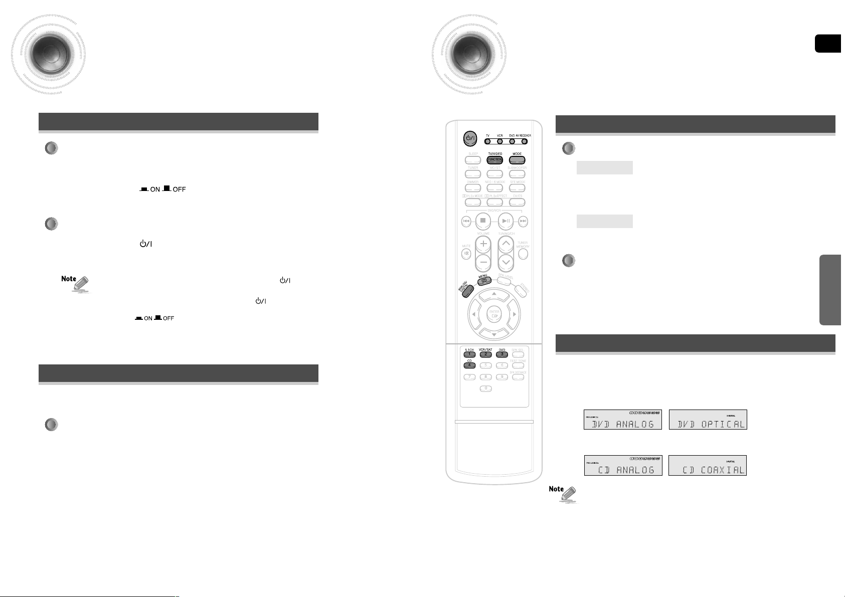
Selecting External Component Input
• You can enjoy Dolby Digital only if you connect the Audio Output jack of an
external audio component to the optical/coaxial digital Audio Input jack on the
main unit.
• You can operate this function only with the remote control.
• This function will be selected in analog only for VCR function, and will not work for 5.1CH
MULTI CH function.
To Select the Function
To Select Analog/Digital Input
REMOTE CONTROL
•
You can directly select 5.1CH, VCR/SAT, DVD, CD.
•
For DVD, VCR/SAT Function
ANALOG and OPTICAL (DVD OPTICAL, V/S OPTICAL) will be selected repetitively.
•
For CD Function
ANALOG and COAXIAL will be selected repetitively.
MAIN UNIT
Press INPUT button.
•
Each time you press the this button, 5.1CH MULTI CH ➝CD ➝DVD ➝ VCR/SAT ➝
FM ➝AM will be selected in turn.
Press the ANALOG/DIGIT AL button.
Method 1
Press DIRECT FUNCTION Select button.
Method 2
Press the FUNCTION button.
•
Each time you press the this button, 5.1CH MULTI CH ➝CD ➝DVD ➝ VCR/SAT ➝
FM ➝AM will be selected in turn.
OPERA TION
Before Using the AV Receiver
Turning On/Of f
Functions of Dedicated Remote Control
Connect the power plug to the outlet.
1
Press the POWER ( ) button of the main unit.
•
This unit will be turned on or off.
2
MAIN UNIT
REMOTE CONTROL
Press MODE button.
•
Each time you press this button, it will select and blink TV indicator ➝VCR indicator
➝DVD indicator ➝ AV Receiver indicator in turn.
•
This unit will not turned on or off even if you press the POWER ( ) button on the
remote control while the main unit is turned off.
•
When you turn off the power by pressing the POWER ( ) button on the remote
control, the unit will be in standby mode.To completely turn off the power, press the
POWER ( ) button of the main unit. Standby indicator will be turned off.
You can operate TV, VCR, DVD, AV Receiver with one remote control.
See pages 45-48 for more details.
15
REMOTE CONTROL
Press the POWER ( ) button of the remote control while main unit is turned on.
•
This unit will be turned on or set to Standby mode.
 Loading...