

Samsung hlr4667w service manual

DLP TV
Chassis : L64C(N_VE Model)_Hurricane-2
Basic Model : HLR5067WX/XAA (HL-R5067W)
Model : HLR4667W1X/XAA (HL-R4667W)
HLR5067W1X/XAA (HL-R5067W)
HLR5667W1X/XAA (HL-R5667W)
HLR6167W1X/XAA (HL-R6167W)
DLP TV FEATURES
■■
HD Built in TV
■
NTSC/ATSC Tuner Embedded
■■
AV network system (Anynet, D-Net)
■
TV Guide On Screen™™system
(Gemstar EPG)
■
Digital Audio output (OPTICAL) jack
■■
Cable CARD™slot
■■
Firmware upgrade by USB Port
SERVICE
Manual
HL-R5067W

This Service Manual is a property of Samsung Electronics Co.,Ltd.
Any unauthorized use of Manual can be punished under applicable
International and/or domestic law.
© Samsung Electronics Co., Ltd. Jul. 2005
Printed in Korea
AA82-02823A
ELECTRONICS

Table of Contents
Chapter 1 Precaution
■ 1-1 Safety Precautions . . . . . . . . . . . . . . . . . . . . . . . . . . . . . . . . . . . . . . . . . . . . . . . . . . . . . . . . . . . 1-1
■ 1-2 Servicing Precautions . . . . . . . . . . . . . . . . . . . . . . . . . . . . . . . . . . . . . . . . . . . . . . . . . . . . . . . . 1-3
■ 1-3 Static Electricity Precautions . . . . . . . . . . . . . . . . . . . . . . . . . . . . . . . . . . . . . . . . . . . . . . . . . . . 1-4
■ 1-4 Installation Precautions . . . . . . . . . . . . . . . . . . . . . . . . . . . . . . . . . . . . . . . . . . . . . . . . . . . . . . . 1-5
Chapter 2 Product Specification
■ 2-1 Product Features . . . . . . . . . . . . . . . . . . . . . . . . . . . . . . . . . . . . . . . . . . . . . . . . . . . . . . . . . . . . 2-1
■ 2-2 Key Features . . . . . . . . . . . . . . . . . . . . . . . . . . . . . . . . . . . . . . . . . . . . . . . . . . . . . . . . . . . . . . . 2-2
■ 2-3 Specifications Analysis . . . . . . . . . . . . . . . . . . . . . . . . . . . . . . . . . . . . . . . . . . . . . . . . . . . . . . . . 2-4
■ 2-4 Accessories . . . . . . . . . . . . . . . . . . . . . . . . . . . . . . . . . . . . . . . . . . . . . . . . . . . . . . . . . . . . . . . . 2-5
Chapter 3 Alignment & Adjustment
■ 3-1 Service Instruction . . . . . . . . . . . . . . . . . . . . . . . . . . . . . . . . . . . . . . . . . . . . . . . . . . . . . . . . . . . 3-1
■ 3-2 How to Access Service Mode . . . . . . . . . . . . . . . . . . . . . . . . . . . . . . . . . . . . . . . . . . . . . . . . . . . 3-2
■ 3-3 Factory Data . . . . . . . . . . . . . . . . . . . . . . . . . . . . . . . . . . . . . . . . . . . . . . . . . . . . . . . . . . . . . . . . 3-3
■ 3-4 Service Adjustment . . . . . . . . . . . . . . . . . . . . . . . . . . . . . . . . . . . . . . . . . . . . . . . . . . . . . . . . . . 3-13
■ 3-5 Software Upgrade . . . . . . . . . . . . . . . . . . . . . . . . . . . . . . . . . . . . . . . . . . . . . . . . . . . . . . . . . . . 3-16
■ 3-6 Replacements & Calibration . . . . . . . . . . . . . . . . . . . . . . . . . . . . . . . . . . . . . . . . . . . . . . . . . . . . 3-17
Chapter 4 Exploded View & Part List
■ 4-1 HLR4667W1X/XAA . . . . . . . . . . . . . . . . . . . . . . . . . . . . . . . . . . . . . . . . . . . . . . . . . . . . . . . . . . 4-1
■ 4-2 HLR5067W1X/XAA . . . . . . . . . . . . . . . . . . . . . . . . . . . . . . . . . . . . . . . . . . . . . . . . . . . . . . . . . . 4-2
■ 4-3 HLR5667W1X/XAA . . . . . . . . . . . . . . . . . . . . . . . . . . . . . . . . . . . . . . . . . . . . . . . . . . . . . . . . . . 4-3
■ 4-4 HLR6167W1X/XAA . . . . . . . . . . . . . . . . . . . . . . . . . . . . . . . . . . . . . . . . . . . . . . . . . . . . . . . . . . 4-4
■ 4-5 L620 Engine Ass'y . . . . . . . . . . . . . . . . . . . . . . . . . . . . . . . . . . . . . . . . . . . . . . . . . . . . . . . . . . . 4-5
Chapter 5 Electrical Part List
■ 5-1 HLR4667W1X/XAA Service Item . . . . . . . . . . . . . . . . . . . . . . . . . . . . . . . . . . . . . . . . . . . . . . . . 5-1
■ 5-2 HLR5067W1X/XAA Service Item . . . . . . . . . . . . . . . . . . . . . . . . . . . . . . . . . . . . . . . . . . . . . . . . 5-2
■ 5-3 HLR5667W1X/XAA Service Item . . . . . . . . . . . . . . . . . . . . . . . . . . . . . . . . . . . . . . . . . . . . . . . . 5-3
■ 5-4 HLR6167W1X/XAA Service Item . . . . . . . . . . . . . . . . . . . . . . . . . . . . . . . . . . . . . . . . . . . . . . . . 5-4
Chapter 6 Troubleshooting
■ 6-1 Checkpoints by Error Mode . . . . . . . . . . . . . . . . . . . . . . . . . . . . . . . . . . . . . . . . . . . . . . . . . . . . 6-1
■ 6-2 Troubleshooting Procedures by Error Modes . . . . . . . . . . . . . . . . . . . . . . . . . . . . . . . . . . . . . . . 6-7
■ 6-3 Troubleshooting Procedures by ASS'Y . . . . . . . . . . . . . . . . . . . . . . . . . . . . . . . . . . . . . . . . . . . 6-9

Chapter 7 Block Diagram
■ 7-1 Overall Block Diagram . . . . . . . . . . . . . . . . . . . . . . . . . . . . . . . . . . . . . . . . . . . . . . . . . . . . . . . . 7-1
■ 7-2 Partial Block Diagram . . . . . . . . . . . . . . . . . . . . . . . . . . . . . . . . . . . . . . . . . . . . . . . . . . . . . . . . . 7-2
Chapter 8 Wiring Diagram
■ 8-1 Overall Wiring . . . . . . . . . . . . . . . . . . . . . . . . . . . . . . . . . . . . . . . . . . . . . . . . . . . . . . . . . . . . . . . 8-1
■ 8-2 Connection between Analog and Digital Board . . . . . . . . . . . . . . . . . . . . . . . . . . . . . . . . . . . . . 8-2
Chapter 9 PCB Diagram
■ 9-1 Power Board . . . . . . . . . . . . . . . . . . . . . . . . . . . . . . . . . . . . . . . . . . . . . . . . . . . . . . . . . . . . . . . 9-1
■ 9-2 Digital Board . . . . . . . . . . . . . . . . . . . . . . . . . . . . . . . . . . . . . . . . . . . . . . . . . . . . . . . . . . . . . . . . 9-3
■ 9-3 Analog Board . . . . . . . . . . . . . . . . . . . . . . . . . . . . . . . . . . . . . . . . . . . . . . . . . . . . . . . . . . . . . . . 9-6
■ 9-4 DMD Board . . . . . . . . . . . . . . . . . . . . . . . . . . . . . . . . . . . . . . . . . . . . . . . . . . . . . . . . . . . . . . . . 9-10
Chapter 10 Schematic Diagram
■ 10-1 Analog Board . . . . . . . . . . . . . . . . . . . . . . . . . . . . . . . . . . . . . . . . . . . . . . . . . . . . . . . . . . . . . . 10-1
■ 10-2 Digital Board . . . . . . . . . . . . . . . . . . . . . . . . . . . . . . . . . . . . . . . . . . . . . . . . . . . . . . . . . . . . . . . 10-10
■ 10-3 DMD Board . . . . . . . . . . . . . . . . . . . . . . . . . . . . . . . . . . . . . . . . . . . . . . . . . . . . . . . . . . . . . . . 10-28
■ 10-4 Actuator Board . . . . . . . . . . . . . . . . . . . . . . . . . . . . . . . . . . . . . . . . . . . . . . . . . . . . . . . . . . . . . 10-35
■ 10-5 Ballast . . . . . . . . . . . . . . . . . . . . . . . . . . . . . . . . . . . . . . . . . . . . . . . . . . . . . . . . . . . . . . . . . . . 10-36
■ 10-6 Power Board . . . . . . . . . . . . . . . . . . . . . . . . . . . . . . . . . . . . . . . . . . . . . . . . . . . . . . . . . . . . . . 10-37
■ 10-7 Combined Bridge and Control Module . . . . . . . . . . . . . . . . . . . . . . . . . . . . . . . . . . . . . . . . . . . 10-38
■ 10-8 Detect . . . . . . . . . . . . . . . . . . . . . . . . . . . . . . . . . . . . . . . . . . . . . . . . . . . . . . . . . . . . . . . . . . . . 10-39
■ 10-9 Side-AV . . . . . . . . . . . . . . . . . . . . . . . . . . . . . . . . . . . . . . . . . . . . . . . . . . . . . . . . . . . . . . . . . . 10-40
■ 10-10 Key Control . . . . . . . . . . . . . . . . . . . . . . . . . . . . . . . . . . . . . . . . . . . . . . . . . . . . . . . . . . . . . . 10-40
■ 10-11 RMC-LED . . . . . . . . . . . . . . . . . . . . . . . . . . . . . . . . . . . . . . . . . . . . . . . . . . . . . . . . . . . . . . . . 10-40
Chapter 11 Operation Instruction & Installation
■ 11-1 Product Features and Functions . . . . . . . . . . . . . . . . . . . . . . . . . . . . . . . . . . . . . . . . . . . . . . . 11-1
■ 11-2 New Features . . . . . . . . . . . . . . . . . . . . . . . . . . . . . . . . . . . . . . . . . . . . . . . . . . . . . . . . . . . . . . 11-5
Chapter 12 Disassembly & Reassembly
■ 12-1 Overall Disassembly & Reassembly . . . . . . . . . . . . . . . . . . . . . . . . . . . . . . . . . . . . . . . . . . . . 12-1
Chapter 13 Circuit Description
■ 13-1 Overall Block Description . . . . . . . . . . . . . . . . . . . . . . . . . . . . . . . . . . . . . . . . . . . . . . . . . . . . . 13-1
■ 13-2 Partial Block Description . . . . . . . . . . . . . . . . . . . . . . . . . . . . . . . . . . . . . . . . . . . . . . . . . . . . . 13-2
■ 13-3 New Circuit Description . . . . . . . . . . . . . . . . . . . . . . . . . . . . . . . . . . . . . . . . . . . . . . . . . . . . . . 13-7
Chapter 14 Reference Information
■ 14-1 Other issues related to other products . . . . . . . . . . . . . . . . . . . . . . . . . . . . . . . . . . . . . . . . . . . 14-1
■ 14-2 Technical Terms . . . . . . . . . . . . . . . . . . . . . . . . . . . . . . . . . . . . . . . . . . . . . . . . . . . . . . . . . . . . 14-3
1. Make sure all protective devices are properly installed
including non-metallic handles and compartment covers
when installing or re-installing the chassis or chassis
assemblies.
2. Make sure that no gaps exist between the cabinets for
children to insert their fingers in to prevent children from
receiving electric shocks.
Errors may occur when the resistance is below 1.0 ㏁ or
over 5.2 ㏁.
In these cases, make sure that the device is repaired
before sending it back to the customer.
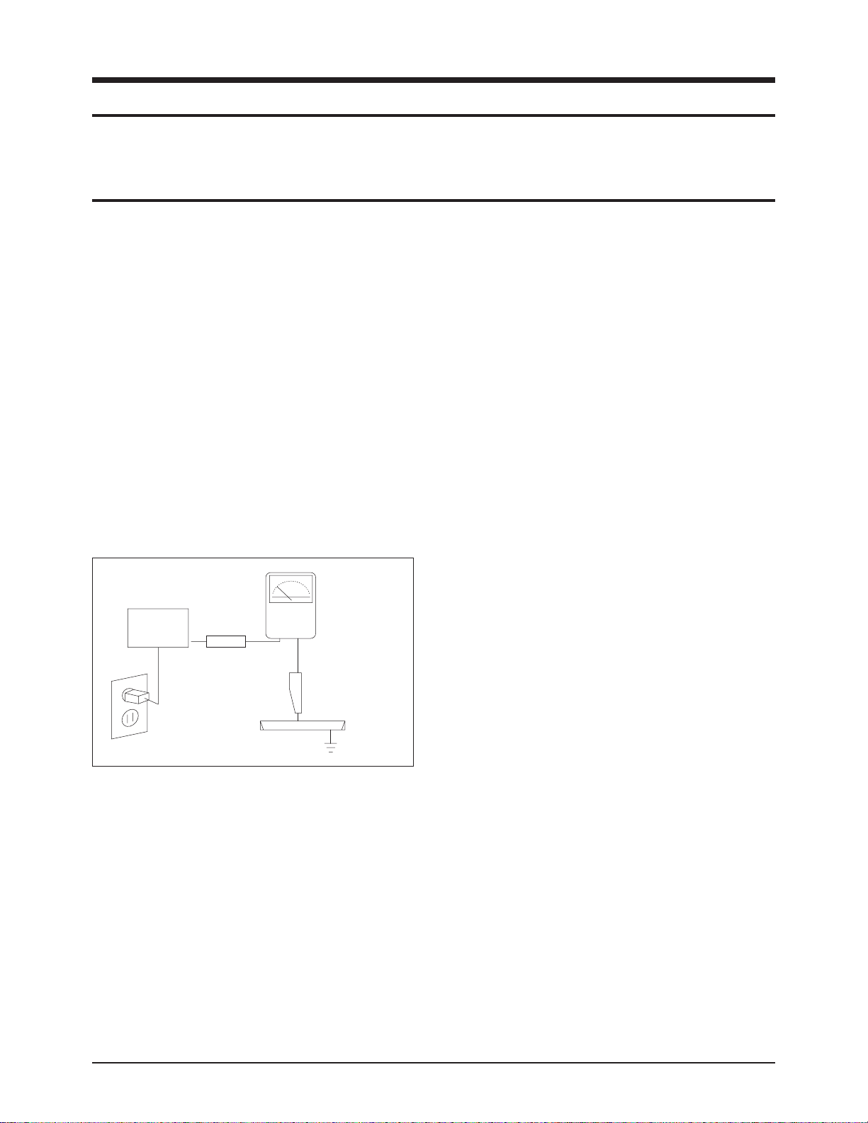
3. Check for Electricity Leakage (Figure 1-1)
Warning: Do not use an insulated transformer for checking the leakage. Use only those current leakage testers
or mirroring systems that comply with ANSIC 101.1 and
the Underwriter Laboratory's specifications (UL1410,
59.7).
Fig. 1-1 AC Leakage Test
4. Ahigh voltage is maintained within the specified limits
using safety parts, calibration and tolerances. When
voltage exceeds the specified limits, check each special
part.
5. Warning for Engineering Changes:
Never make any changes or additions to the circuit
design or the internal part for this product.
Ex: Do not add any audio or video accessory
connectors. This might cause physical damage.
Furthermore, any changes or additions to the original
design/engineering will invalidate the warranty.
6. Warning - Hot Chassis:
Some TV chassis are directly connected to one end of
the AC power cord for electrical reasons.
Without insulated transformers, the product can only be
repaired safely when the chassis is connected to the
earthed end of the AC power source.
To make sure the AC power cord is properly connected,
follow the instructions below. Use the voltmeter to
measure the voltage between the chassis and the
earthed ground. If the measurement is over 1.0V, unplug
the AC power cord and change the polarity before reinserting it. Measure the voltage between the chassis
and the ground again.
7. Some TV chassis are shipped with an additional
secondary grounding system. The secondary system is
adjacent to the AC power line. These two grounding
systems are separated in the circuit using an
unbreakable/unchangeable insulation material.
8. When any parts, material or wiring appear overheated or
damaged, replace them with new regular ones
immediately. When any damage or overheating is
detected, correct this immediately and make a regular
check of possible errors.
9. Check for the original shape of the lead, especially that
of the antenna wiring, any sharp edges, the AC power
and the high voltage power. Carefully check if the wiring
is too tight, incorrectly placed or loose. Never change the
space between the part and the printed circuit board.
Check the AC power cord for possible damages. Keep
the part or the lead away from any heat-emitting
materials.
Precaution
Samsung Electronics 1-1
To avoid possible damages or electric shocks or exposure to radiation, follow the instructions below with regard to safety,
installation, service and ESD.
1. Precaution
1-1 Safety Precautions
(READING SHOULD
DEVICE
UNDER
TEST
EXPOSED METAL
2-WIRE CORD
ALSO TEST WITH
PLUG REVERSED
(USING AC ADAPTER
PLUG AS REQUIRED)
TEST ALL
SURFACES
LEAKAGE
CURRENT
TESTER
NOT BE ABOVE
0.5mA)
EARTH
GROUND

10. Safety Indication:
Some electrical circuits or device related materials
require special attention to their safety features, which
cannot be viewed by the naked eye. If an original part is
replaced with another irregular one, the safety or
protective features will be lost even if the new one has a
higher voltage or more watts.
Critical safety parts should be bracketed with ( ).
Use only regular parts for replacements (in particular,
flame resistance and dielectric strength specifications).
Irregular parts or materials may cause electric shock or
fire.
11. Pay additional attention to the current leakage as the
voltage between the power board and the ballast is 220
to 440v, i.e. very high.
And also beware of possible electric shock from the
primary power source.
Precaution
1-2 Samsung Electronics
!

1. The service instructions are printed on the cabinet, and
should be followed by any service personnel.
2. Make sure to unplug the AC power cord from the power
source before starting any repairs.
(a) Remove or re-install parts or assemblies.
(b) Disconnect the electric plug or connector, if any.
(c) Connect the test part in parallel with the electrolytic
capacitor.
3. Some parts are placed at a higher position than the
printed board. Insulated tubes or tapes are used for this
purpose. The internal wiring is clamped using buckles to
avoid contact with heat emitting parts. These parts are
installed back to their original position.
4. After the repair, make sure to check if the screws, parts
or cables are properly installed. Make sure no damage is
caused to the repaired part and its surroundings.
5. Check for insulation between the blade of the AC plug
and that of any conductive materials (i.e. the metal
panel, input terminal, earphone jack, etc).
6. Insulation Check Process: Unplug the power cord from
the AC source and turn the switch on. Connect the insulating resistance meter (500v) to the AC plug blade.
The insulating resistance between the blade of the AC
plug and that of the conductive material should be more
than 1 ㏁.
7. Any B+ interlock should not be damaged.
If the metal heat sink is not properly installed, no
connection to the AC power should be made.
8. Make sure the grounding lead of the tester is connected
to the chassis ground before connecting to the positive
lead. The ground lead of the tester should be removed
last.
9. Beware of risks of any current leakage coming into
contact with the high-capacity capacitor.
10. The sharp edges of the metal material may cause
physical damage, so ensure wearing protective gloves
during the repair.
Precaution
Samsung Electronics 1-3
Warning 1: First carefully read the "Safety Instruction" in this service manual.
When there is a conflict between the service and the safety instructions, follow the safety instruction at all times.
Warning 2: Any electrolytic capacitor with the wrong polarity will explode.
1-2 Servicing Precautions

1-3 Static Electricity Precautions
1. Some semi-conductive ("solid state") devices are
vulnerable to static electricity. These devices are known
as ESD. ESD includes the integrated circuit and the field
effect transistor. To avoid any materials damage from
electrostatic shock, follow the instructions described
below.
2. Remove any static electricity from your body by
connecting the earth ground before handling any
semi-conductive parts or ass'ys. Alternatively, wear a
dischargeable wrist-belt.
(Make sure to remove any static electricity before
connecting the power source - this is a safety instruction
for avoiding electric shock)
3. Remove the ESD ass'y and place it on a conductive
surface such as aluminum foil to prevent accumulating
static electricity.
4. Do not use any Freon-based chemicals.
Such chemicals will generate static electricity that
causes damage to the ESD.
5. Use only grounded-tip irons for soldering purposes.
6. Use only anti-static solder removal devices.
Most solder removal devices do not support an
anti-static feature. Asolder removal device without an
anti-static feature can store enough static electricity to
cause damage to the ESD.
7. Do not remove the ESD from the protective box until the
replacement is ready. Most ESD replacements are
covered with lead, which will cause a short to the entire
unit due to the conductive foam, aluminum foil or other
conductive materials.
8. Remove the protective material from the ESD
replacement lead immediately after connecting it to the
chassis or circuit ass'y.
9. Take extreme caution in handling any uncovered ESD
replacements. Actions such as brushing clothes or lifting
your leg from the carpet floor can generate enough static
electricity to damage the ESD.
Precaution
1-4 Samsung Electronics
CAUTION
These servicing instructions are for use by
qualified service personnel only.
To reduce the risk of electric shock do not
perform any servicing other than that contained in the
operating instructions unless you are qualified to do so.

Precaution
Samsung Electronics 1-5
1-4 Installation Precautions
1. For safety reasons, more than two people are required
for carrying the product.
2. Keep the power cord away from any heat emitting
devices, as a melted covering may cause fire or electric
shock.
3. When installing the product, make sure to keep it away
from the wall (more than 10cm/4 inches) for ventilation
purposes.
Poor ventilation may cause an increase in the internal
temperature of the product, resulting in a shortened
component life and degraded performance.
4. Bend the external antenna cable when connecting it to
the product. This is a measure to protect it from being
exposed to moisture. Otherwise, it may cause a fire or
electric shock.
5. Make sure to turn the power off and unplug the power
cord from the outlet before repositioning the product.
Also check the antenna cable or the external connectors
if they are fully unplugged. Damage to the cord may
cause fire or electric shock.
6. Keep the antenna far away from any high-voltage cables
and install it firmly. Contact with the high-voltage cable or
the antenna falling over may cause fire or electric shock.
7. When connecting the RF antenna, check for a DTV
receiving system and install a separate DTV reception
antenna for areas with no DTV signal.
8. Check the basics of the screen test.
- Image position/size, Tilt adjustment, Actuator activation

1-6 Samsung Electronics
MEMO
Product Specification
Samsung Electronics 2-1
2. Product Specification
2-1 Product Features
Block Specfication Major IC Remark
DMD - Panel Resolution : 1280 x 720 (Diamond Pixel) HD4 DMD Panel(L620 Engine)
RF
- Integrated HDTV Tuner
(NTSC/ATSC/QAM TUNER Embedded)
ATI T313
Power
- Input Voltage : AC110V
- Stand-By : under 30W
Stand-by (KA1M0565)
Video
-DNIe3-NTSC, ATSC-HDMI, PC
-3D Comb filter
ADV7401, ATI X226B,
uPD64083
Sound
- Speaker : 20W x 2
- Trusurround XT, Dolby Digital
MSP4440
Cabinet - L6 Design
■ Chip Description
- ATI x226B : Xilleon 226 is the most advanced and highly integrated component for digital set-top boxes, information appliances,
and televisions. Xilleon 226 provides dual-stream high-definition decode and display, an assortment of peripheral
device controllers, and an embedded microprocessor.
- ADV7401 : The ADV7401 is an integrated video decoder that automatically indicates and converts High Definition or Standard
Definition analog baseband television signal into a 4:2:2 component digital video data stream compatible with 20/16bit or 10/8-Bit CCIR601/CCIR656 outputs for standard definition & SMPTE293M/296M/274M & ITU-R.BT1358 for
High definition. All RGB graphics signals are output as 30-bit 4:4:4 RGB or 20-bit 4:2:2 YCrCb.
- MSP4440 : The MSP 44x0G family of single-chip Multistandard Sound Processors covers the sound processing of all analog
TV-Standards worldwide, as well as the NICAM digital sound standards.
- ATI T313 : ATI T313 is an advanced QAM, NTSC, and VSB demodulator chip designed to operate in the Digital Cable Ready,
analog NTSC, and ATSC terrestrial broadcast environments. ATI T313 also incorporates a QPSK forward data
channel (FDC) receiver and a BTSC/Dual-FM demodulator and decoder enabling a complete digital and analog TV
solution with a minimum number of components.
- uPD64083 : uPD64083 realizes a high precision Y/C separation and a noise reduction by the three-dimension signal
processing for NTSC signal.
Product Specification
2-2 Samsung Electronics
2-2 Key Features
■ H/W Configuration
- DMD Panel : 0.55" (1280 x 720p, TI)
- 1 Optical Engine for the Panel : Slim and Cost-effective
- Color Wheel : R/G/B Color Implementation
- Lamp : 100W (10,000 hours) → Dynamic Mode 120W Drive (6,000 hours)
- 2 NTSC/ATSC/QAM Tuners : NTSC/DTV Reception
- Support HDMI Interface : Adopts DVI/HDMI systems for digital HDs including STB.
- DNIe3 : High quality image implementation
- AnyNet Feature : An enhanced interface for various external devices
- USB Interface : Use the USB interface for service purposes (S/W Upgrade)
■ S/W Configuration
- MCU : Built-in 300 MHz MIPS X226B CPU
- 4-Layered Architecture : Device Driver/OS/Hardware Abstraction/Application
- OSD : 32Bit True Color Graphics OSD
- Enhanced system stability by separating the DTV control and the application control systems into multi-processes.
■ Picture
- DMD Panel
*Panel Size : 0.55"
*Panel Resolution : 1280 x 720 (Diamond Pixel)
- Tuner : Integrated HDTV Tuner (NTSC/ATSC/QAM TUNER Embbeded)
- Display Format : 1280 x 720 (Diamond Pixel)
■ Sound
- Sound System : Dolby Digital
- Amp/Channel : 2 Channel Digital Amp
- Speaker System & Output(RMS)
*Main L/R : 15W + 15W
*Sound (RMS) : 15W + 15W
■ In/Out Terminals
- Side : 1 CVBS In, 1 S-VHS In
- Rear : 2 RF In, 2 CVBS In, 2 S-VHS In, 2 Component In,
1 HDMI In(DVI Comportable With Adaptive Jack Only), 1 Anynet port, 2 IEEE1394, 1 Gemstar IR out, 1 Optical audio,
1 POD Card slot
Model HL-R4667W HL-R5067W HL-R5667W HL-R6167W
Voltage AC 110~120V
Frequency of Operation 60Hz
Power Consumption 230 watts
Dimensions
(W x D x H)
42.83 x 13.44 x 32.05 inches
1088 x 341.5 x 814 mm
46.54 x 14.00 x 34.25 inches
1182 x 355.5 x 870 mm
52.36 x 15.26 x 37.87 inches
1330 x 387.5 x 962 mm
56.93 x 18.37 x 41.59 inches
1446 x 466.5 x 1056.5 mm
Weight 30.3 Kg / 66.80 lbs 33 Kg / 72.75 lbs 36.7 Kg / 80.91 lbs 42.9 Kg / 94.58 lbs
Product Specification
Samsung Electronics 2-3
■ Feature
- Component Interface (480i/480p/720p/1080i, Y/Pb/Pr)
- Digital Interface : HDMI
- Graphic Interface : PC
- Language : English/French/Spanish
- PIP : HD/SD PiP
- Picture Size : 4:3/16:9/Zoom1/Zoom2/Panorama
- V-CHIP
- Closed Caption
- Sleep Timer : 180 Min.
- Anynet Interface
- IEEE1394
- Optical sound output
- Gemstar IR output
- POD
■ Remocon
- TM76
■ Power Supply
- 110V
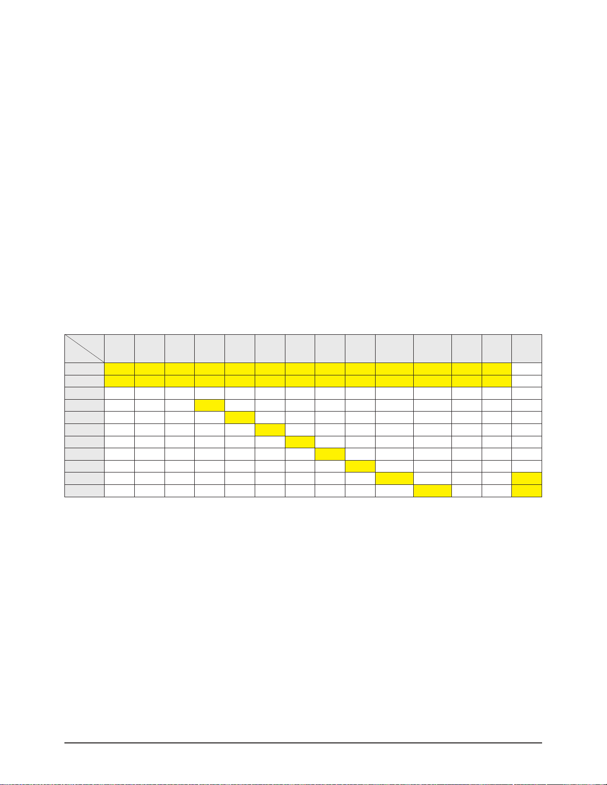
■ PIP Settings (X : PIP doesn't operate, ▲: PIP operate and swap doesn't operate, ○: PIP and swap operate)
Main
Sub
ATSC QAM NTSC AV1 AV2 AV3 S-Video1 S-Video2 S-Video3 Component1 Component2 HDMI PC D-Net
ATSC
X X X X X X X X X X X X X ▲
QAM
X X X X X X X X X X X X X ▲
NTSC
▲ ▲ O O O O O O O O O ▲ ▲ ▲
AV1
▲ ▲ O X O O O O O O O ▲ ▲ ▲
AV2
▲ ▲ O O X O O O O O O ▲ ▲ ▲
AV3
▲ ▲ O O O X O O O O O ▲ ▲ ▲
S-Video1
▲ ▲ O O O O X O O O O ▲ ▲ ▲
S-Video2
▲ ▲ O O O O O X O O O ▲ ▲ ▲
S-Video3
▲ ▲ O O O O O O X O O ▲ ▲ ▲
Component1
▲ ▲ O O O O O O O X O ▲ ▲ X
Component2
▲ ▲ O O O O O O O O X ▲ ▲ X
Product Specification
2-4 Samsung Electronics
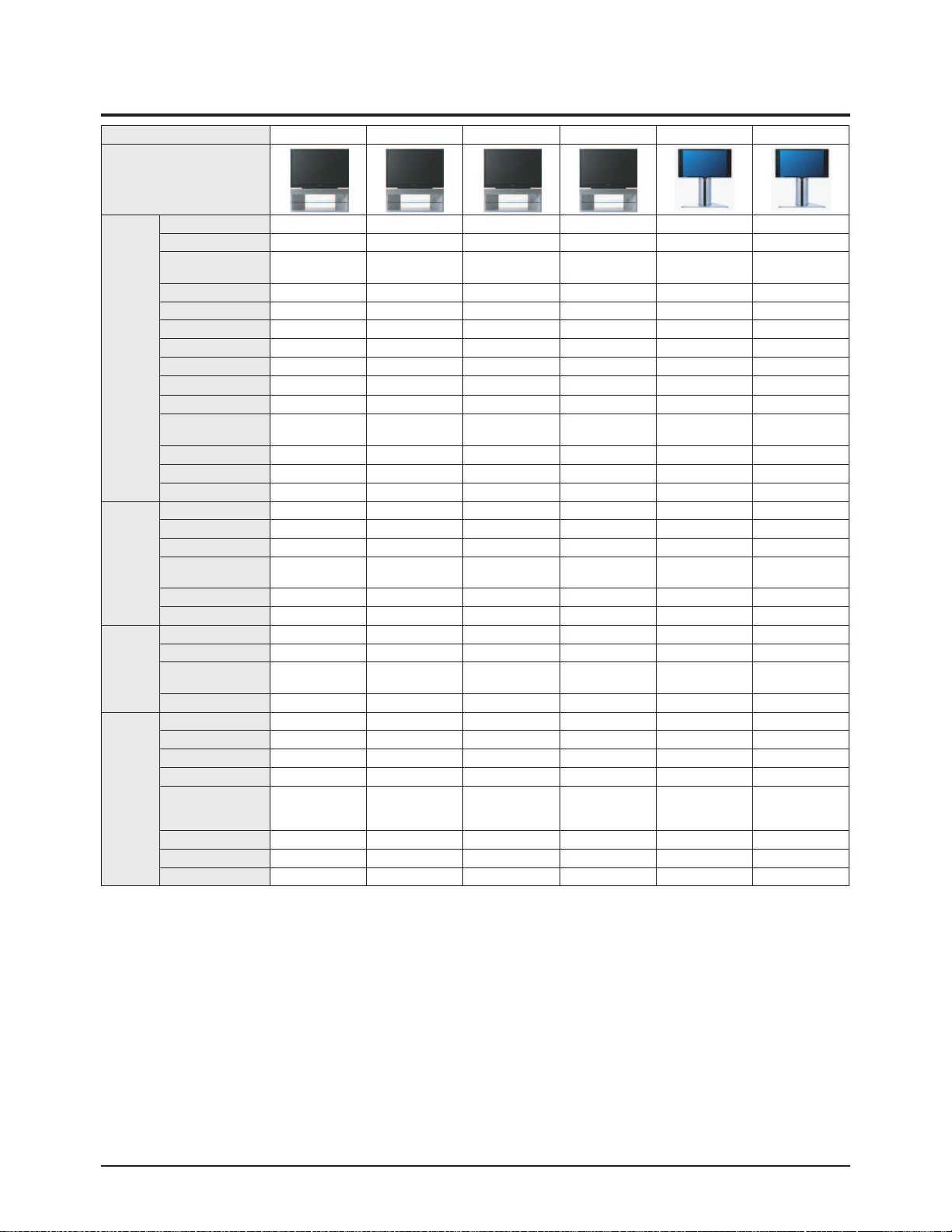
2-3 Specifications Analysis
Model HL-R4667W HL-R5067W HL-R5667W HL-R6167W HL-R5087W HL-R5687W
Design
Picture
Display Device DLP DLP DLP DLP DLP DLP
Built-in Tuner ATSC, NTSC ATSC, NTSC ATSC, NTSC ATSC, NTSC ATSC, NTSC ATSC, NTSC
Display Format
1080i, 720p, 480p,
480i
1080i, 720p, 480p,
480i
1080i, 720p, 480p,
480i
1080i, 720p, 480p,
480i
1080i, 720p, 480p,
480i
1080i, 720p, 480p,
480i
Screen Size 46 inch 50 inch 56 inch 61 inch 50 inch 56 inch
Aspect ratio 16:9 16:9 16:9 16:9 16:9 16:9
Progressive scan Yes Yes Yes Yes Yes Yes
Digital Comb Filter 3D Comb 3D Comb 3D Comb 3D Comb 3D Comb 3D Comb
First Surface Mirror Yes Yes Yes Yes Yes Yes
Brightness
750cd/㎡ 750cd/㎡ 750cd/㎡ 750cd/㎡ 800cd/㎡ 800cd/㎡
Contrast 1500:1 1500:1 1500:1 1500:1 2500:1 2500:1
Color Wheel Size/Bearing
7segment/65¢,
Air Bearing
7segment/65¢,
Air Bearing
7segment/65¢,
Air Bearing
7segment/65¢,
Air Bearing
7segment/65¢,
Air Bearing
7segment/65¢,
Air Bearing
Anti-glare Sun Screen Yes Yes Yes Yes Yes Yes
Screen Pitch 0.098mm 0.098mm 0.098mm 0.098mm 0.098mm 0.098mm
Image enhancer DNIe3 DNIe3 DNIe3 DNIe3 DNIe3 DNIe3
Audio
Base/Tremble/Balance No No No No No No
Equalizer 5 Band 5 Band 5 Band 5 Band 5 Band 5 Band
Auto Volume Leveler Yes Yes Yes Yes Yes Yes
Surround Sound
TruSurround XT
Dolby Digital
TruSurround XT
Dolby Digital
TruSurround XT
Dolby Digital
TruSurround XT
Dolby Digital
TruSurround XT
Dolby Digital
TruSurround XT
Dolby Digital
Speaker system 2 Way 4 Speaker 2 Way 4 Speaker 2 Way 4 Speaker 2 Way 4 Speaker 2 Way 4 Speaker 2 Way 4 Speaker
Output Power 15Wx2 15Wx2 15Wx2 15Wx2 15Wx2 15Wx2
Features
2-Tuner Split-Screen PIP Yes(HD/SD) Yes(HD/SD) Yes(HD/SD) Yes(HD/SD) Yes(HD/SD) Yes(HD/SD)
Split-screen Side-by-Side Yes Yes Yes Yes Yes Yes
MTS with dbx Noise
Reduction/SAP
Yes Yes Yes Yes Yes Yes
Still Picture Yes Yes Yes Yes Yes Yes
Connections
Plug & Play Yes Yes Yes Yes Yes Yes
EPG Gemstar EPG Gemstar EPG Gemstar EPG Gemstar EPG Gemstar EPG Gemstar EPG
Anynet Yes Yes Yes Yes Yes Yes
S-Video In Rear 2/Side 1 Rear 2/Side 1 Rear 2/Side 1 Rear 2/Side 1 Rear 2 Rear 2
HDTV Component
Video Input (Y, Pb, Pr)
1080i/480P/480i
Rear 2 Rear 2 Rear 2 Rear 2 Rear 2 Rear 2
PC Yes Yes Yes Yes No No
HDMI Yes Yes Yes Yes Yes Yes
Digital Sound Optical 1 Optical 1 Optical 1 Optical 1 Optical 1 Optical 1
Product Specification
Samsung Electronics 2-5
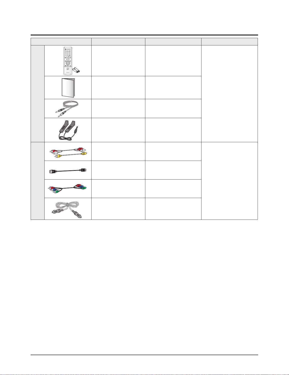
2-4 Accessories
Accessories Item Item code Remark
SuppliedAccessories
Remocon
Alkaline Battery
BP59-00071B
4301-000103
Samsung Service center
Manual BP68-00469A
ANYNET cable BN39-00518B
G-Link Cable MD96-00036A
Accessories that canbepurchased
additionally
Video Cable /
Audio Cable
-
Internal shopping mall
Antenna Cable -
Component Cable -
Optical Cable -

2-6 Samsung Electronics
MEMO
Alignment & Adjustment
Samsung Electronics 3-1
3. Alignment & Adjustment
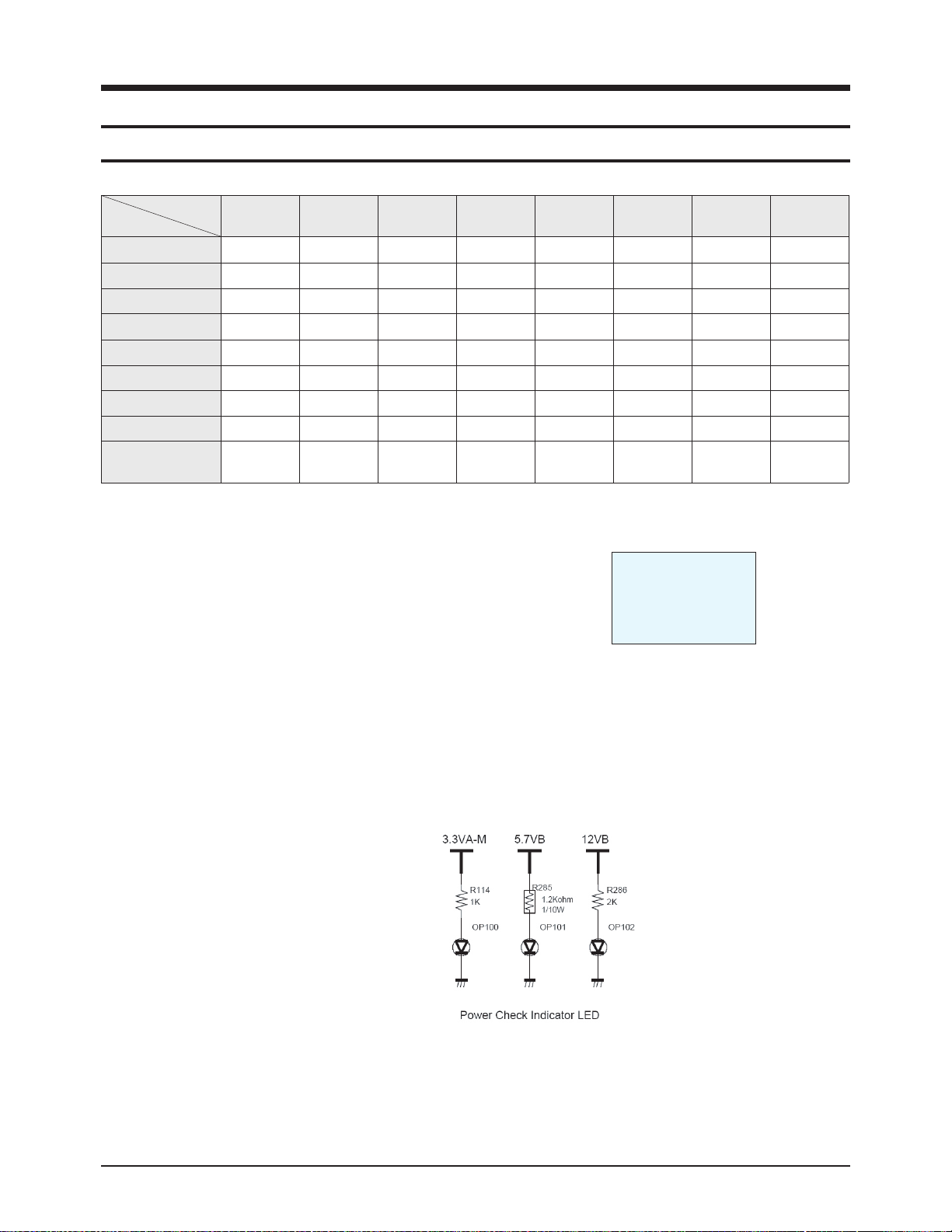
3-1 Service Instruction
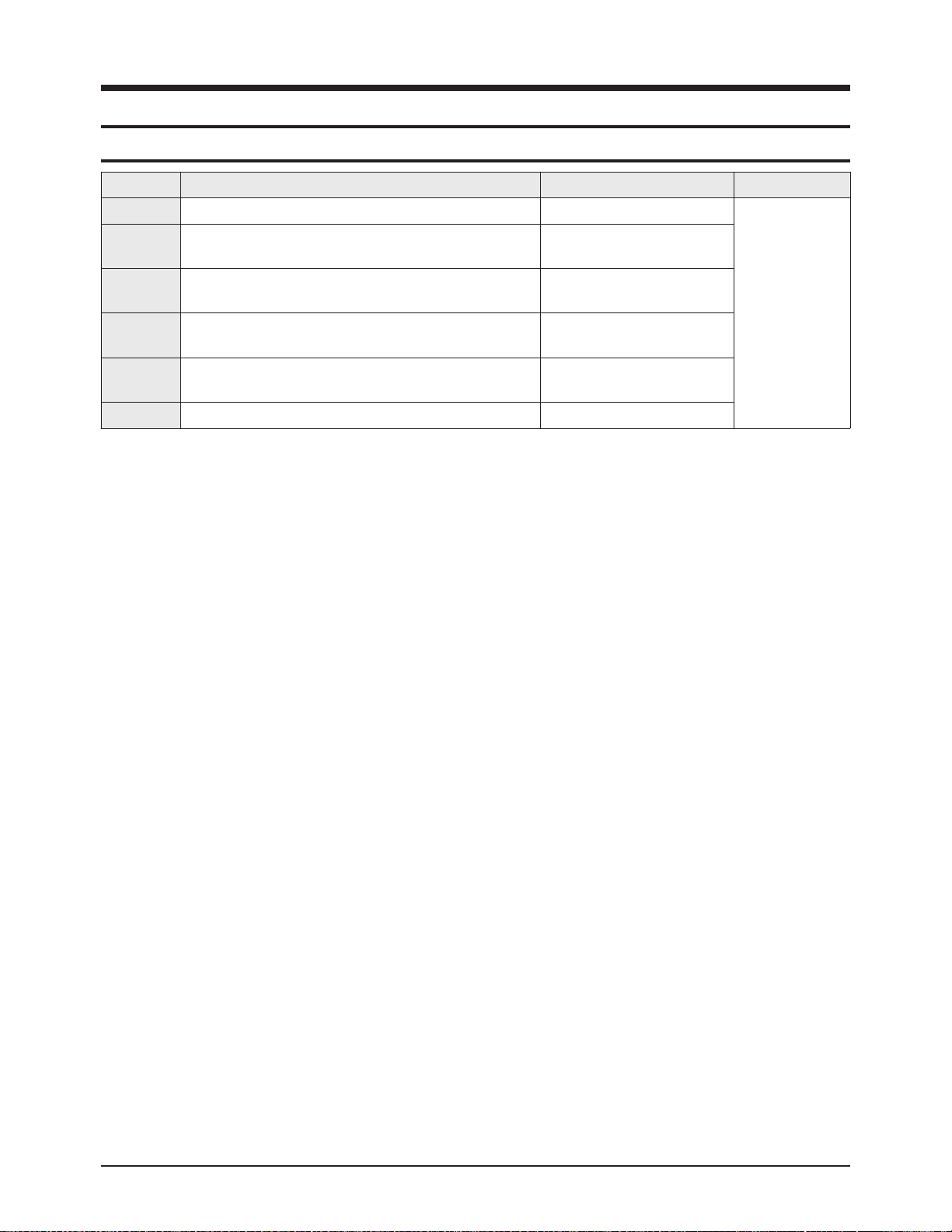
■ Check items listed after changing each
※ If you change digital board and optical engine, check in order.
( For example, in case of "D/B", first 'S/W', second 'V/H position' and third 'Index'...)
1. Software version check :
After Entering the Service mode, Check the list below
* S/W Notation
"T_HURRAUS0_0004" indicates "HURRICANE BASIC MODEL USA, ver. 0004".
2. Front LED check : See page 6-11.
3. Index Delay adjustment : See page 3-13.
4. Actuator Gain adjustment : See page 3-15.
5. Vertical / Horizontal Position adjustment : See page 3-13.
6. CCA: See page 3-14.
7. Board LED check : Check all the LED are turned on.
8. Tilt/Focus adjustment : See page 3-17.
Check Items
Replaced Items
S/W Version Front LED Index Delay
Actuator
Gain
V-Position
H-Position
CCA Board LED Tilt Focus
Digital Board
●(1st) ●(3rd) ●(5th) ●(2nd) ●(4th)
Analog Board
● ●
Power Board
● ●
Optical Engine
●
●(3rd) ●(5th) ●(2nd) ●(4th) ●(1st)
DMD Board
● ●
Lamp
● ●
Color Wheel
●
Front LED Assy
●
Actuator
Subdetector Board
●
T_HURRAUS0_0004
2005_XX_XX
T-DTVUCOM5-00XX
T-HURRAUS0_00XX
Alignment & Adjustment
3-2 Samsung Electronics
3-2 How to Access Service Mode
1. Turn off the power to put the unit into the STAND-BY mode.
2. In order to enter the Service Mode, Press "Mute" → "1” → "8" → "2" → "POWER" button on the Remote Control.
In case entry into SERVICE MODE is unsuccessful, repeat the procedures above.
3. Initial DISPLAYState in times of Service Mode Switch overs
4. Buttons operations within Service Mode
DDP1011(L6)
DNIe
ADV7401(M)
ADV7401(S)
Xilleon226
uPD64083
MSP4440
CCA(ON)
Cinema CCA
SP Actuator
ESP
CHECKSUM 0000
OPTION
SERVICE
T_HUR2AUS0_XXXX
200X_XX_XX
T-HURUCOM5-XXXX
T-HUR2AUS1_XXXX
MENU Full Menu Display / Move to Parent Menu
Direction keys ▲ / ▼
Item Selection by Moving the Cursor
Direction keys ◀ / ▶
Data Increase/Decrease for the Selected Item
Source Cycles through the active input source that are connected to the unit
Alignment & Adjustment
Samsung Electronics 3-3
3-3 Factory Data
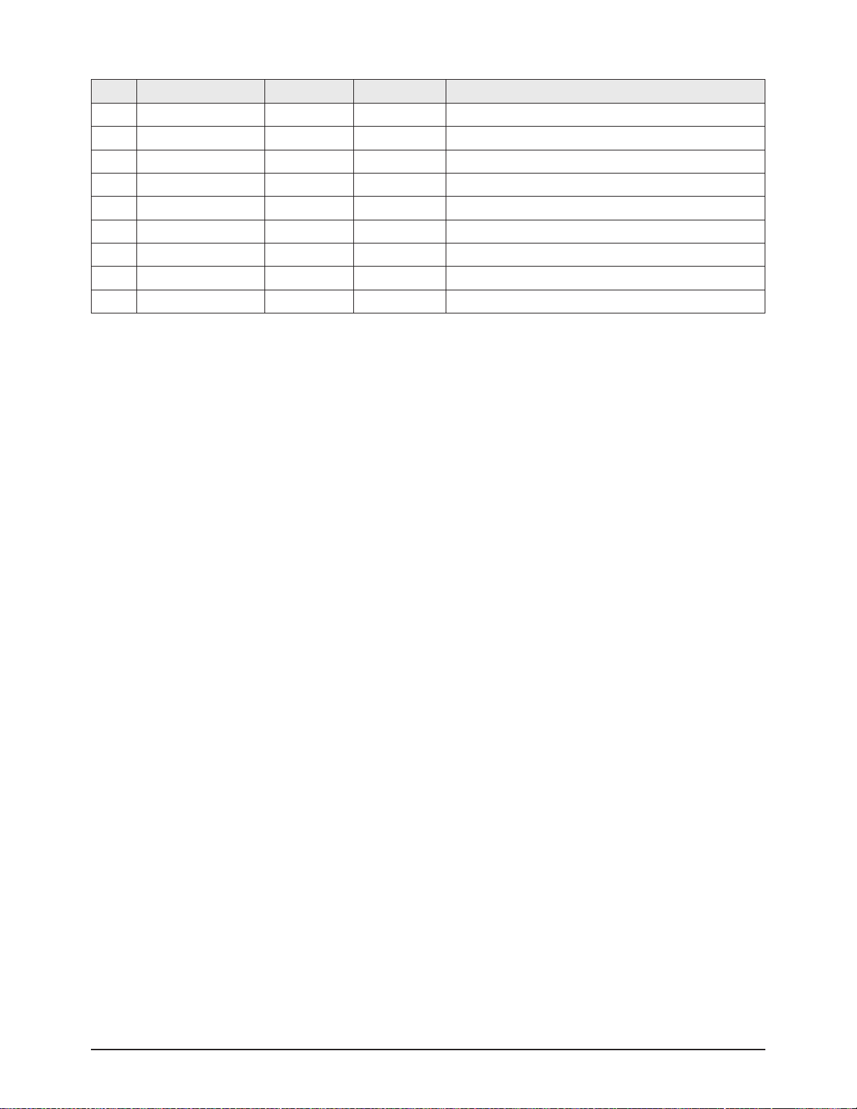
1. DDP1011
No Item Range Default Remark
1 V
-Position
0-60 36 Screen upper and lower adjustment
2 H-Position 0~120 60 Screen left and right adjustments
3 LAMPSYNC Pulse(P) Pulse(P), Pass(T)
4 INDEX DELAY 0~359 40
Synchronizes the base position of the color wheel with the
corresponding color signal.
This is critical to the natural color display. If the index delay
is not properly set, even the correct CCAcordinates will not
help when displaying natural colors.
5 SEQ SELECT 0~15 5 Sequence Selection
6 V-FLIP Normal/Flip Normal Vertica Flip Operation
7 H-FLIP Normal/Flip Normal Horizontal Flip Operation
8 GAMMA 0 ~ 15 2 Gamma Table Selection
9 SLR OFF/ON OFF SLR Funcion On/Off
10 DMD_BIAS B,C,D,E E DMD Bias pin voltage selection
11 Lamp Boost 0~63 20 Lamp Boost value selection
12 Lamp Sync Delay 0~4095 0 Lamp Sync delay value selection
13 Engine Select SAMSUNG SAMSUNG and ZEISS Selection
14 Lamp Watt 120W 120W/132W Selection
15 Lamp Select Philips Philips/Osram/Ushio
16 T
est Pattern
0
This displays the built-in pattern of the DDP1011 chip.
DDP1011 drives the DMD panel, so displaying this pattern
means there is no error in the DDP1011 projection function
and the panel itself.
★ The underlined are items applied during the service adjustment. None of the others should be adjusted.
Alignment & Adjustment
3-4 Samsung Electronics
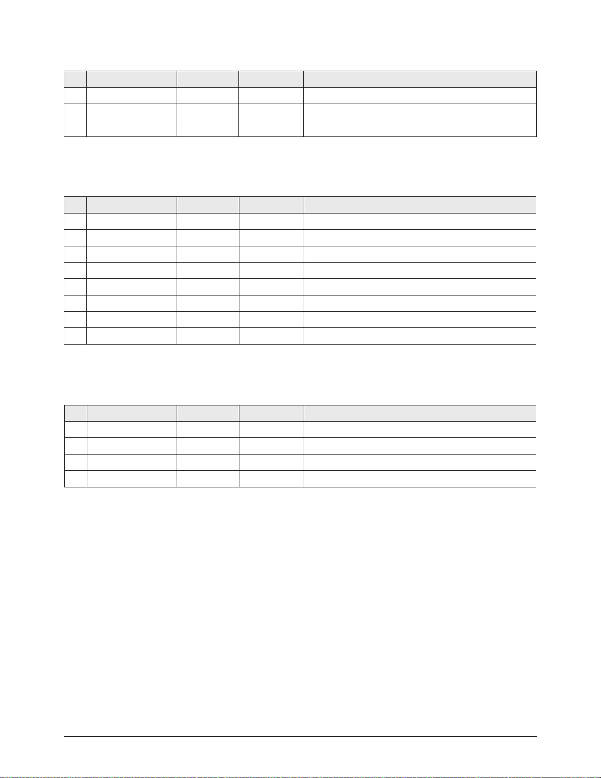
2. DNIe
No Item Range Default Remark
1 Test Pattern 0 Test Pattern Selection
2 NR_MAX Y/C 0~255 48 Temporal NR Gain
3 NR_MIN Y/C 0~255 16 Temporal NR Gain
4 Core 0~15 4 NEOnDCE User Set Up
5 B_RATIO 12000 Low level information for the minimum value
6 BLACK_TILT 0~255 120 Black Stretch Area
7 W_RATIO 12000 High level information for the minimum value
8 WHITE_TILT 0~255 200 White Stretch Area
9 GAIN1X 0~63 30 Gain of horizontal high frequency region
10 GAIN1Y 0~63 20 Gain of vertical high frequency region
11 GAIN2X 0~63 17 Gain of horizontal middle frequency region
12 GAIN2Y 0~63 13 Gain of vertical middle frequency region
13 GAIN3X 0~63 11 Gain of horizontal low frequency region
14 NDON ON ON,OFF Background Noise Detection ON/OFF Switch
15 CORING_ON ON ON,OFFCoring On/Off
16 SCALE_R 0~255 160 Log Mapping Gain
17 WTE_CSC YCCRGB YCCRGB,YPPRGB
18 DITHER_MOD 0 1,2,3
19 RED_C_COEFF 128 Gain adjustment of the contrast for the Red signal
20 GRN_C_COEFF 128 Gain adjustment of the contrast for the Green signal
21 BLU_C_COEFF 128 Gain adjustment of the contrast for the Blue signal
22 RED_B_COEFF 128 Gain adjustment of the brightness for the Red signal
23 GRN_B_COEFF 128 Gain adjustment of the brightness for the Green signal
24 BLU_B_COEFF 128 Gain adjustment of the brightness for the Blue signal
25 Sub Contrast 0~150 120 Brightness adjustment for the high-light parts of the screen
26 Sub Brightness 230 Brightness adjustment for the low-light parts of the screen
27 ALPMAU/L 0~255 50

Alignment & Adjustment
Samsung Electronics 3-5
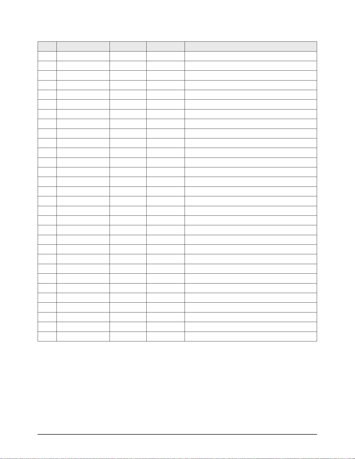
3. ADV7401(M)
No Item Range Default Remark
1 AUTO COLOR Auto Color function execution
2 SOG_SYNC_LEV Embedded Sync Trigger Level
3 AGC_TIM AGC Time Constant Selection
4 GAIN_MAN ON,OFF Manual Gain Control Enable
5 A_GAIN Manual Gain Value for Channel A
6 B_GAIN Manual Gain Value for Channel B
7 C_GAIN Manual Gain Value for Channel C
8 A_OFFSET Channel A Offset
9 B_OFFSET Channel B Offset
10 C_OFFSET Channel C Offset
11 YPM 0~7 4 Y Peaking Filter Mode
12 YSFM 0~32 1 Y Shaping Filter Mode
13 WYSFM 0~32 19 Wide Band TY Shaping Filter Mode
14 CSFM 0 C Shaping Filter Mode
15 Contrast 0~255 128 Contrast Adjust
16 Brightness 0~255 128 Brightness Adjust
17 Hue 0~255 128 Hue Adjust
18 CKILLTHR 0~7 3 Colour Kill Threshold
19 SD_OFF_Cb 0~255 128 SD Offset Cb Channel
20 SD_OFF_Cr 0~255 128 SD Offset Cr Channel
21 SD_SAT_Cb 0~255 128 Saturation Cb Channel
22 SD_SAT_Cr 0~255 128 Saturation Cr Channel
23 IFFILTSEL 0~7 3 IF Filter Select
24 LTA 0~3 0 Luma Timing Adjust
25 CTA 0~7 2 Chroma Timing Adjust
26 DNR_TH1 0~255 0 DNR Noise Threshold
27 DCT 0~3 0 Digital Clamp Timing
28 LAGC 0~7 0 Luma Automatic Gain Control
29 LAGT 0~3 3 Luma Automatic Gain Timing
30 LMG 1144 Luma Manual Gain
31 CAGC 0~7 5 Chroma Automatic Gain Control
32 CAGT 0~3 3 Chroma Automatic Gain Timing
33 CMG 2458 Chroma Manual Gain
34 CTI_AB_EN ON
ON,OFF Chroma Transient Improvement Alpha Blend
Enable
35 CTI_AB 0~3 3 Chroma Transient Improvement Alpha Blend
Alignment & Adjustment
3-6 Samsung Electronics
No Item Range Default Remark
36 CTI_C_TH 0~255 8 CTI Chroma Threshold
37 NSFSEL 0~3 0 Split Filter Selection NTSC
38 CTAPSN 0~3 2 Chroma Comb Taps NTSC
39 CCMN 0~7 0 Chroma Comb mode NTSC
40 YCMN 0~7 0
41 HSSLICE
42 VSSLICE
43 DLL_PH
44 ST_NOISE OxFFFF
45 ALIAS_FILTER_EN
46 DNR_TH2 4
Alignment & Adjustment
Samsung Electronics 3-7
4. ADV7401(S)
No Item Range Default Remark
1 AUTO COLOR Auto Color function execution
2 SOG_SYNC_LEV 0~31 11 Embedded Sync Trigger Level
3 AGC_TIM 0~7 0 AGC Time Constant Selection
4 GAIN_MAN ON ON,OFF Manual Gain Control Enable
5 A_GAIN 0~1024 275 Manual Gain Value for Channel A
6 B_GAIN 0~1024 287 Manual Gain Value for Channel B
7 C_GAIN 0~1024 287 Manual Gain Value for Channel C
8 A_OFFSET 0~1024 0 Channel A Offset
9 B_OFFSET 0~1024 512 Channel B Offset
10 C_OFFSET 0~1024 512 Channel C Offset
11 YPM 0~7 4 Y Peaking Filter Mode
12 YSFM 0~32 1 Y Shaping Filter Mode
13 WYSFM 0~32 19 Wide Band TY Shaping Filter Mode
14 CSFM (0~7) 0 C Shaping Filter Mode
15 Contrast 0~255 128 Contrast Adjust
16 Brightness 0~255 126 Brightness Adjust
17 Hue 0~255 128 Hue Adjust
18 CKILLTHR 0~7 3 Colour Kill Threshold
19 SD_OFF_Cb 0~255 128 SD Offset Cb Channel
20 SD_OFF_Cr 0~255 128 SD Offset Cr Channel
21 SD_SAT_Cb 0~255 128 Saturation Cb Channel
22 SD_SAT_Cr 0~255 128 Saturation Cr Channel
23 IFFILTSEL 0~7 3 IF Filter Select
24 LTA 0~3 0 Luma Timing Adjust
25 CTA 0~7 3 Chroma Timing Adjust
26 DNR_TH 0~255 0 DNR Noise Threshold
27 DCT 0~3 0 Digital Clamp Timing
28 LAGC 0~7 0 Luma Automatic Gain Control
29 LAGT 0~3 3 Luma Automatic Gain Timing
30 LMG 0~4096 1064 Luma Manual Gain
31 CAGC 0~7(0~3) 2 Chroma Automatic Gain Control
32 CAGT 0~3 3 Chroma Automatic Gain Timing
33 CMG 0~4096 2458 Chroma Manual Gain
34 CTI_AB_EN ON
ON,OFF Chroma Transient Improvement Alpha Blend
Enable
35 CTI_AB 0~3 3 Chroma Transient Improvement Alpha Blend
Alignment & Adjustment
3-8 Samsung Electronics
No Item Range Default Remark
36 CTI_C_TH 0~255 8 CTI Chroma Threshold
37 NSFSEL 0~3 0 Split Filter Selection NTSC
38 CTAPSN 0~3 2 Chroma Comb Taps NTSC
39 CCMN 0~7 0 Chroma Comb mode NTSC
40 YCMIN 0~7 0
41 HSSLICE 0~3 1
42 VSSLICE 0~3 3
43 DLL_PH
44 ST_NOISE OxFFFF
Alignment & Adjustment
Samsung Electronics 3-9
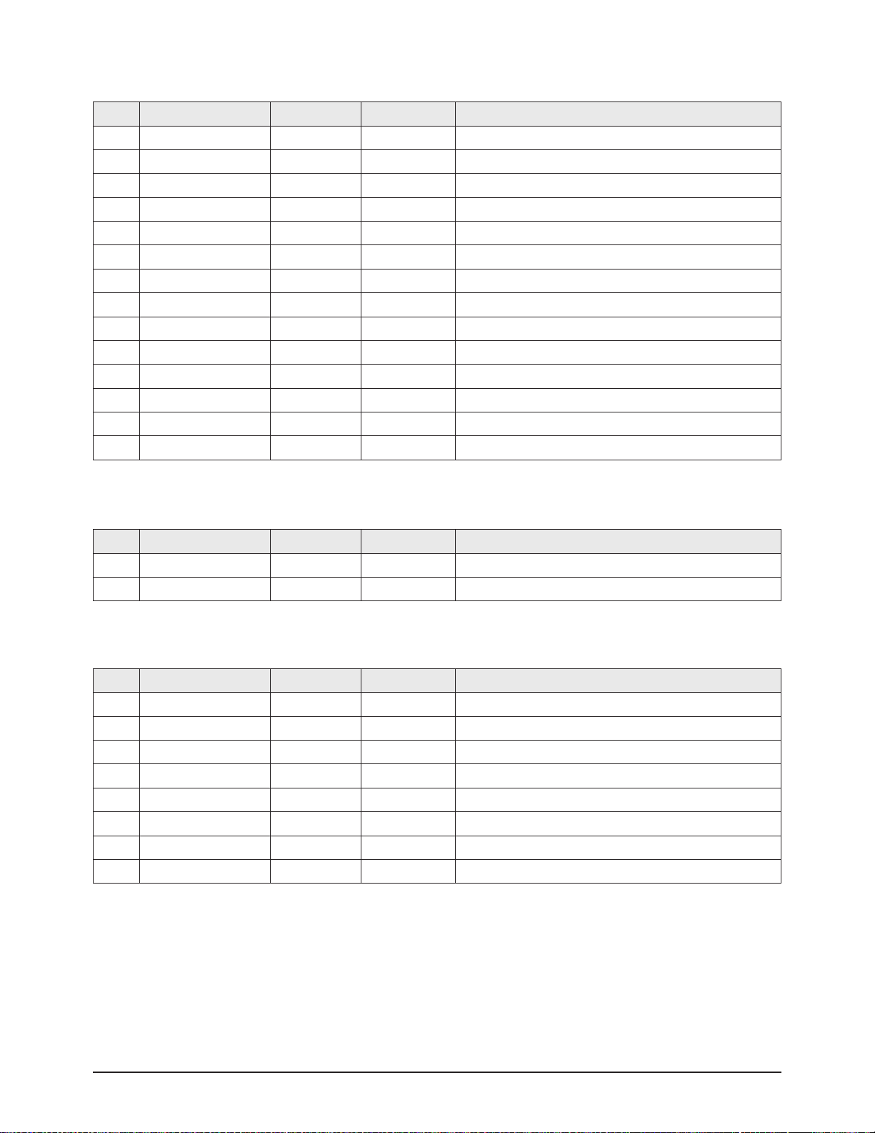
6. Upd64083
No Item Range Default Remark
1 DYCOR 0 ~ 15 2 DY detection coring level
2 DYGAIN 0 ~ 15 9 DY detection gain
3 DCCOR 0 ~ 15 3 DC detection coring level
4 DCGAIN 0 ~ 15 6 DC detection gain
5 YHCOR 0 ~ 3 1 Y output high frequency component coring
6 CDELAY 0 ~ 3 4 C signal output delay
7 YPFT 3 YPFT adjustment
8 YPFG 8 YPFG adjustment
7. MSP4440
No Item Range Default Remark
1 MDB Effect 0~127 56 Micronas Dynamic Bass
2 SRS Dialog 0~127 64 SRS Dialog clarity adjustment
3 PLL Pilot low adjustment
4 PLH Pilot high adjustment
5. Xilleon226
No Item Range Default Remark
1 Main/Sub Main
2 Y/UV Y
3 Filter gh121a
Alignment & Adjustment
3-10 Samsung Electronics
8. CCA(ON)
No Item Range Default Remark
1 CCA On/Off On CCA On/Off Selection
2 Red-x 0~32768 640 Red-x adjustment
3 Red-y 0~32768 340 Red-y adjustment
4 Red-Y 0~32768 86 Red-Y adjustment
5 Green-x 0~32768 300 Green-x adjustment
6 Green-y 0~32768 620 Green-y adjustment
7 Green-Y 0~32768 300 Green-Yadjustment
8 Blue-x 0~32768 150 Blue-x adjustment
9 Blue-y 0~32768 60 Blue-y adjustment
10 Blue-Y 0~32768 53 Blue-Y adjustment
11 White-x 0~32768 291 White-x adjustment
12 White-y 0~32768 300 White-y adjustment
13 White-Y 0~32768 439 White-Y adjustment
14 WB Spread Spread CCAvalue to all mode
15 Move HDMI Move to the HDMI Mode
16 DRedX Target Red X value for CCA
17 DRedY Target Red Y value for CCA
18 DGreenX Target Green X value for CCA
19 DGreenY Target Green Y value for CCA
20 DBlueX Target Blue X value for CCA
21 DBlueY Target Blue Y value for CCA
22 DCyanX Target Cyan X value for CCA
23 DCyanY Target Cyan Y value for CCA
24 DMagentaX Target Magenta X value for CCA
25 DMagentaY Target Magenta Y value for CCA
26 DYellowX Target Yellow X value for CCA
27 DYellowY Target Yellow Y value for CCA
28 D_White_X Target White X value for CCA
29 D_White_Y Target White Y value for CCA
30 ATV/AV/SV
Alignment & Adjustment
Samsung Electronics 3-11
9. Cinema CCA
No Item Range Default Remark
1 DRedX 640 Target Red X value for CCA
2 DRedY 340 Target Red Y value for CCA
3 DGreenX 300 Target Green X value for CCA
4 DGreenY 620 Target Green Y value for CCA
5 DBlueX 150 Target Blue X value for CCA
6 DBlueY 60 Target Blue Yvalue for CCA
7 DCyanX 205 Target Cyan X value for CCA
8 DCyanY 270 Target Cyan Y value for CCA
9 DMagentaX 290 Target Magenta X value for CCA
10 DMagentaY 140 Target Magenta Y value for CCA
11 DYellowX 425 Target Yellow X value for CCA
12 DYellowY 515 Target Yellow Y value for CCA
13 D-White-X 313 Target White X value for CCA
14 D-White-Y 329 Target White Y value for CCA
11. ESP
No Item Range Default Remark
1 Dynamic Con Off Dynamic Contrast On/Off
2 Dynamic Strength Medium Low/Mid/Mas
3 Dynamic Con Gain 0~100 0 Dynamic Contrast Gain Adjustment
4 Dynamic Sat Off Dynamic Saturation On/Off
5 Dynamic Sat Gain 0~255 176 Dynamic Saturation Gain Adjustment
6 Sharp Picture Off Sharp Picture On/Off
7 Sharp Filter HD Low HD High/HD Low/SD Image
8 Sharp Picture Gain 0~255 176 Sharp Picture Gain Adjustment
10. SPActuator
12. CHECKSUM 0000
Excute Checksum calcuation
No Item Range Default Remark
1 Actuator Gain 0~175 115 Actuator Gain adjustment
2 Actuator On/Off On Actuator On/Off selection

Alignment & Adjustment
3-12 Samsung Electronics
13. OPTION
No Item Range Default Remark
1 Lamp Clear Initialize lamp usage time. Lamp Life is set to zero
2 All setting is back to the default
3 WB Reset OFF Initialize the White Balance value
4 EER Reset Clear the EEPROM
5 Lamp Life 0h Lamp on time counter
6 AUTO POWER ON/OFF ON
The sets turns on automatically when the power cord is
plugged in
7 DNle DEMO ON/OFF ON DNle Demo function selection
8 Lamp Control Dynamic Dynamic, Always
9 MUTE TIME 600ms
Time which the screen will be black while switching
channels
10 EDID WRITE
11 DELAY MOD ON/OFF OFF Sound Delay Module ON/OFF selection
12 DBG/ANY SEL Debug/AnyNet Select the use of the Anynet jack
13 GEM/GEMIR SEL GemIR/Gemstar Not used
14 226 TEST PATT Xilleon 226 test pattern
15 Set Default Data Initialize Service Data
16 DDC protection OFF DDC write ON/OFF selection
17 LNA Default AUTO LNAsetting OFF/Auto selection
18 PROTECT ON Protection ON/OFF selection
19 WATCH DOG Watch Dog ON/OFF selection
20 WD COUNT 0 Count for Watch Dog event
21 Auto Pgm Range 8 Not used
22
DIGITAL→DMD
Transfer engine adjustment data from digital to DMD
23
DMD→DIGITAL
Transfer engine adjustment data from DMD to digital
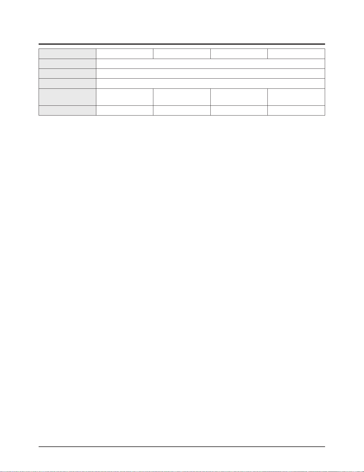
14. SERVICE
No Item Range Default Remark
1 V-Position 0 ~ 60 30 Screen upper and lower adjustment
2 H-Position 0 ~ 120 60 Screen left right adjustment
3 LAMPSYNC Pulse/Pass Pulse
4 Actuator Gain 105 Actuator Gain adjustment
5 INDEX DELAY 0 ~ 1023 166 Index delay adjustment
6 AUTO COLOR OFF Auto Color function execution
7 CCA CCAmenu
8 Lamp Clear Initialize Lamp usage time
9 User Reset All setting is back to the default
10 Engine Select SAMSUNG SAMSUNG and ZEISS Selection
11 Lamp Watt 120W 120W/132W Selection
12 Lamp Select Philips Philips/Osram/Ushio

Alignment & Adjustment
Samsung Electronics 3-13
3-4 Service Adjustment
3-4-1 Vertical / Horizontal Position Adjustment
1. Turn off the power to put the unit into the STAND-BY mode.
2. In order to enter the Service Mode, Press "Mute" → "1" → "8" → "2" → "POWER" button on the Remote Control.
3. Select "Service" on the first display of the Service mode menu.
4. Select the V-position for vertical positioning and H-position for horizontal positioning by using the ▲▼(up, down) buttons.
※ Do not set the V-position value to 34 or 35. (Setting to these values will cause horizontal lines on the right side of the screen.)
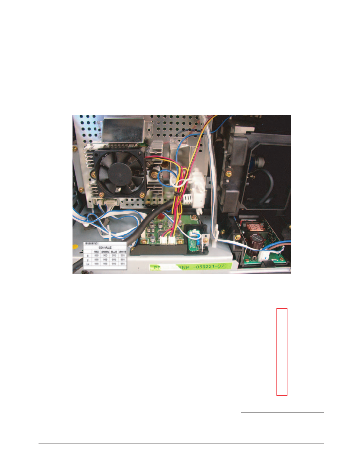
3-4-2 INDEX DELAY Adjustment
1. Turn off the power to put the unit into the STAND-BY mode.
2. In order to enter the Service Mode, Press "Mute" → "1" → "8" → "2" → "POWER" button on the Remote Control.
3. Select "Service" on the first display of the Service mode menu.
4. Press the ▲▼(Up or Down) button to move to INDEX DELAY, then press ENTER to select.
5. The INDEX DELAY setup screen (with a red bar at the bottom of the screen) will be displayed.
6. Press the ◀▶ (Left of Right) button to check the red color at the bottom of the screen at its minimum and maximum values of
changing from red to magenta, then adjust to the mean value.
Alignment & Adjustment
3-14 Samsung Electronics
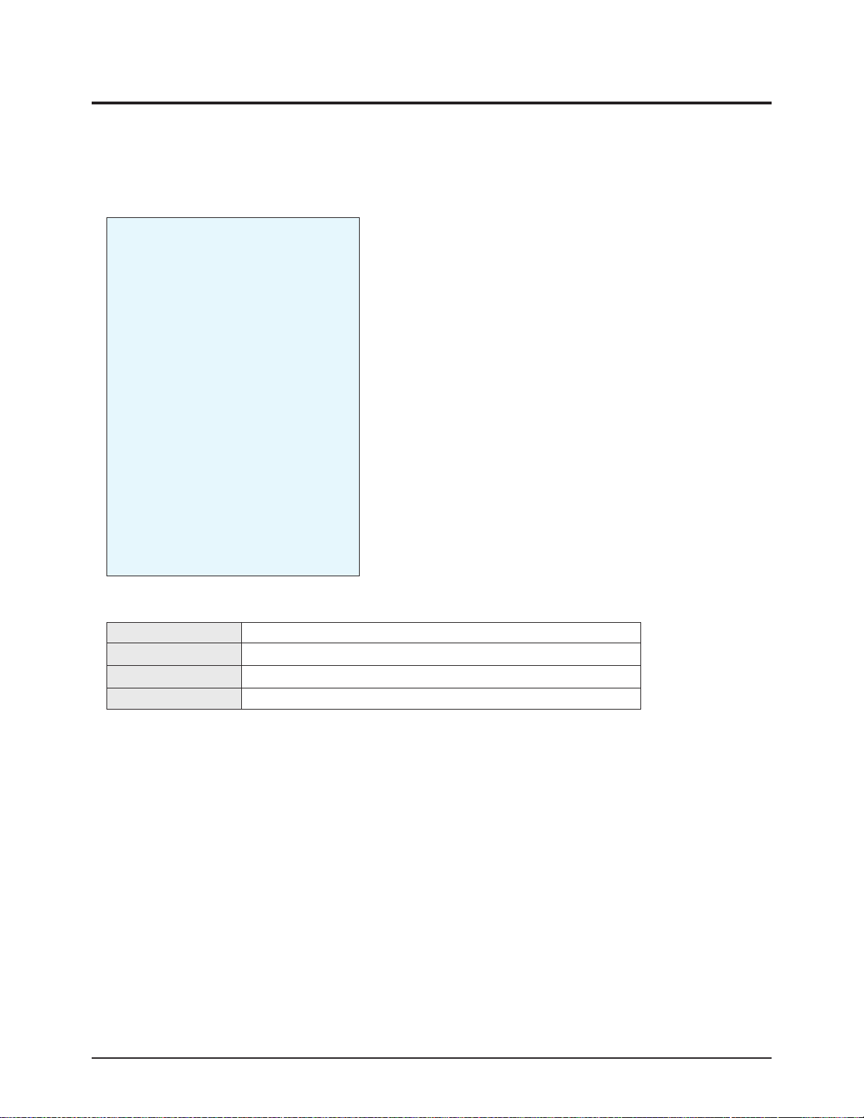
3-4-3 CCA Adjustment Service Methods : CCAAdjustment is needed after changing a light engine or digital board
■ CCA : In DLPTV, even the same RGB color may differ depending on the light engine. CCA(Color Coordinate Adjustment)
corrects the color to achieve the color accuracy. CCAperforms color correction after measuring and inputting the current
light engine's data on actual color coordinates for displayed Red, Green, Blue, and White color patterns, using a color
coordinate measuring equipment.
At this moment, color correction is performed on the basis of previously inputted Desired Color Coordinates and
Measured Color Coordinates. Measured Data on Service Engine's color coordinates is presented on the CCAlabel.
Input the label values to perform CCAcolor correction.
1. Condition of the CCALabel upon Receipt of the Service Engine
*"CCALABEL" describes the measured color coordinates on the light engine.
2. CCAService Procedures
To execute CCA adjustment , perform the following steps :
1) Turn off the power to put the unit into the STAND-BY mode.
2) In order to enter the Service Mode, Press "Mute" → "1" → "8" → "2" → "POWER"
button on the Remote Control.
3) From the Factory Service Mode Menu; select SERVICE > CCA.
4) Switch the CCAOFF.
5) Enter the CCARed, Green, Blue and White basic engine data to the DLP.
6) Input the D-White-x, y values in the coordinates per destination. (if necessary)
7) Select WB SPREAD, then press Enter to activate the WB Spread SET ensuring that
you adjust until you get the OK sign. After adjusting, exit Factory Mode.
8) When the adjustment is complete, check the picture quality.
*Attention
Performing CCAis independent on current display's resolution and input signal type if you
don't measure color coordinates data.
Measuring color coordinates data requires specific equipment not possessed by service per
sonnel, that makes performing manual adjustment impossible. Adjusting CCAis applied to all the signal mode.
Don't change Desired value because it will be hamful to the color of the SET.
CCAMenu in FACTORY Mode
CCAON/OFF
Red - x : ???
Red - y : ???
Red - Y : ???
Green - x : ???
Green - y : ???
Green - Y : ???
Blue - x : ???
Blue - y : ???
Blue - Y : ???
White - x : ???
White - y : ???
White - Y : ???
WB SPREAD
Move HDMI
 Loading...