

Samsung HL-R5067W, HL-R6167W, HL-R4667W, HL-R5667W User Manual

Owner’s Instructions
HL-R4667W
HL-R5067W
HL-R5667W
HL-R6167W
This device is a Class B digital apparatus.
Register your product at www.samsung.com/global/register

Trademark Notice
In the United States, TV GUIDE and other related marks are registered marks of Gemstar-TV Guide
International, Inc. and/or one of its affiliates. In Canada, TV GUIDE is a registered mark of
Transcontinental Inc., and is used under license by Gemstar-TV Guide International, Inc.
Aux États Unis TV GUIDE et d’autres marques relatives sont des marques déposées de
Gemstar-TV Guide International, Inc. et/ou d’une de ses sociétés affiliées. Au Canada TV GUIDE
est une marque déposée de Transcontinental Inc., utilisée sous licence de Gemstar-TV Guide
International, Inc.
En los Estados Unidos, TV GUIDE y otras marcas relacionadas son marcas registradas de
Gemstar-TV Guide International, Inc. y/o una de sus empresas afiliadas. En Canadá, TV GUIDE
es una marca registrada de Transcontinental Inc., y se utiliza bajo licencia de Gemstar-TV Guide
International, Inc.
License Notice
The TV Guide On Screen system is manufactured under license from Gemstar-TV Guide
International, Inc. and/or one of its affiliates.
Le système TV Guide On Screen est fabriqués sous licence de Gemstar-TV Guide International, Inc.
et/ou d’une de ses sociétés affiliées.
El sistema TV Guide On Screen se fabrica bajo licencia de Gemstar-TV Guide International, Inc.
y/o una de sus empresas afiliadas.
Patent Notice
The TV Guide On Screen system is protected by one or more of the following issued United States
patents 6,498,895, 6,418,556, 6,331,877; 6,239,794; 6,154,203; 5,940,073; 4,908,713;
4,751,578; 4,706,121.
Le système TV Guide On Screen est protégés par un ou plusieurs brevets émis aux États Unis,
comme le 6,498,895, 6,418,556, 6,331,877; 6,239,794; 6,154,203; 5,940,073; 4,908,713;
4,751,578; 4,706,121.
El sistema TV Guide On Screen está protegido por una o más de las siguientes patentes emitidas
en los Estados Unidos: 6,498,895 ; 6,418,556; 6,331,877; 6,239,794 ; 6,154,203 ;
5,940,073 ; 4,908,713 ; 4,751,578 ; 4,706,121.
English - 2

A Guide to Digital TV
• What is Digital Television?
Digital television (DTV) is a new way of transmitting high quality video and audio to your TV set.
Using DTV, broadcasters can transmit high definition TV (HDTV) images, Dolby digital surround
audio, and new services such as multicasting (transmitting more than one program on the same
TV channel) and datacasting. Several of these services can be combined into a single digital
broadcast.
Digital Television Services
• Digital Picture Quality
DTV programs are transmitted in two different formats. The first is Standard Definition Television
(SDTV) and the second is High Definition Television (HDTV).
• SDTV program formats include 480-line interlaced (480i) and 480-line progressive (480p) video.
480i programs are essentially a digital version of our current analog TV programs, while the 480p
format offers improved image detail over 480i. Some 480p programs are broadcast in widescreen
and are comparable to progressive-scan DVD movies in image quality.
• HDTV program formats include 1080-line interlaced (1080i) and 720-line progressive (720p).
Both HDTV formats are always broadcast in widescreen, and offer much higher picture quality than
SDTV.
•Dolby Surround Sound
With DTV, you can listen to a variety of Dolby digital audio formats from Dolby Surround 2.0 to
Dolby Digital 5.1 surround, using your home audio system. Many HDTV programs are now
broadcast with DD 5.1 soundtracks.
U.S.A Only
The product unit accompanying this user manual is licensed under certain intellectual property rights of certain third
parties. In particular, this product is licensed under the following US patents:
5,991,715, 5,740,317, 4,972,484, 5,214,678, 5,323,396, 5,539,829, 5,606,618, 5,530,655, 5,777,992,
6,289,308, 5,610,985, 5,481,643, 5,544,247, 5,960,037, 6,023,490, 5,878,080, and under US Published
Patent Application No. 2001-44713-A1.
This license is limited to private non-commercial use by end-user consumers for licensed contents. No rights are
granted for commercial use. The license does not cover any product unit other than this product unit and the license
does not extend to any unlicensed product unit or process conforming to ISO/IEC 11172-3 or ISO/IEC 13818-3 used
or sold in combination with this product unit. The license only covers the use of this product unit to encode and/or
decode audio files conforming to the ISO/IEC 11172-3 or ISO/IEC 13818-3. No rights are granted under this license
for product features or functions that do not conform to the ISO/IEC 11172-3 or ISO/IEC 13818-3.
Other countries
The product unit accompanying this user manual is licensed under certain intellectual property rights of certain
third parties. This license is limited to private non-commercial use by end-user consumers for licensed contents.
No rights are granted for commercial use. The license does not cover any product unit other than this product unit
and the license does not extend to any unlicensed product unit or process conforming to ISO/IEC 11172-3 or
ISO/IEC 13818-3 used or sold in combination with this product unit. The license only covers the use of this
product unit to encode and/or decode audio files conforming to the ISO/IEC 11172-3 or ISO/IEC 13818-3.
No rights are granted under this license for product features or functions that do not conform to the ISO/IEC
11172-3 or ISO/IEC 13818-3.
English - 3

CableCARD and Digital Cable Ready TVs
CableCARD and Digital Cable Ready TVs are the products of a new digital cable standard.
This new standard is called OpenCable and it is a concerted effort to standardize the digital cable
service network interface in North America. For more information, please refer to www.cablelabs.com.
Digital Cable Ready TVs are equipped with a proper digital cable tuner to receive digital cable signals
from your local cable service provider. They are also designed to work with digital cable card modules
(PCMCIA card modules called CableCARDs). These PCMCIA card modules or CableCARDs will be
provided by your local cable service provider after a proper subscription process.
The provided CableCARD from your local cable service provider needs to be inserted into the
CableCARD slot of a Digital Cable Ready TV. Please refer to page 22 for how to insert the CableCARD.
A digital set-top box which used to be provided by the cable service provider is no longer needed with
Digital Cable Ready TVs and CableCARDs.
When CableCARD is inserted into the slot, the TV screen will show the message that CableCARD is
inserted and tries to download necessary data such as channel information or subscription information
from your digital cable service provider. When you insert CableCARD for the first time, this process
could take few minutes depending on the amount of data your cable provider needs to send.
During this process the digital cable service provider or CableCARD may display messages on the TV
screen to help or give you further information.
Please contact your local cable provider for more information on service availability and how to
acquire a CableCARD.
NOTE
• This television receiver supports the copy protection system regulated by DTLA (Digital Transmission
Licensing Administrator). It should be noted that copy protected content may not be viewable
depending on your particular connections.
English - 4

Q&A
1. Is the antenna I use for existing TV reception good enough for DTV?
Over-the-air (OTA) digital TV broadcasting uses the same channels as analog TV and works well
with many existing TV antennas. However, DTV broadcast channel assignments are different than
analog channels. You should find out whether your local DTV broadcasts are on VHF (channels
2-13) or UHF (channels 14-69) to see if you need a different antenna.
If your DTV channels are on UHF and you already get good UHF reception, your present antenna
may work fine. The same holds true for VHF DTV reception. Note that in some markets, both VHF
and UHF channels are used for DTV broadcasts.
You can find out the latest DTV channel assignments for your area by browsing selected Internet
web sites such as www.titantv.com, www.10000watts.com, and www.fcc.gov.
2. How difficult is it to receive DTV signals indoors?
This depends on whether your local DTV stations are running full power or not and how close your
location is to the transmission tower. DTV receivers do not require as much signal as analog TV
receivers to produce high-quality images and sound.
Once the DTV signal level exceeds a certain threshold at the receiver, the digital video and audio
data is decoded at the same quality it was originally encoded for broadcast.
This is a big advantage for DTV over analog TV - there is no noise, ghosting, static, or scratchy
audio.
3. How can I connect an antenna in my townhouse, co-operative apartment,
condominium, or apartment?
The Federal Communications Commission’s OTARD Rule (part of the Telecommunications Act of
1996) allows residents of condominiums, townhouse, or members of neighborhood associations to
put up outside antennas for reception of broadcast TV signals as long as those antennas are not
located in common areas and are no more than 12’ in height.
Residents of rental units (apartments, etc.) are not covered by the OTARD rules and will have to use
indoor antennas to receive DTV broadcasts. It is possible that the landlord of an apartment complex
can provide broadcast DTV signals via a master TV antenna system to each apartment.
4. Can I connect my DTV set-top receiver to my cable TV service?
Cable TV systems use a different method for transmitting digital TV programs that is currently
incompatible with broadcast DTV set-top receivers. So you will still need to use an outdoor or
indoor antenna to receive OTA broadcast DTV programs.
The good news is that you won’t have to pay a monthly or per-program charge to watch OTA DTV
and HDTV programs. They’re free, unlike subscription satellite TV or premium cable TV. All you
need is an antenna and a DTV set-top receiver to enjoy clear, sharp widescreen images and
high-quality audio.
5. I hear a Clicking sound in standby mode.
You will hear the sound if you have set both ANTENNA (Air) and Cable to “Yes” in the TV Guide
On Screen
However, do not worry about this since the sound comes from inside your TV while it receives data
for your TV Guide.
TM
Setup.
English - 5

Table of Contents
Your New Wide TV.................................................................................10
Viewing Position ....................................................................................................10
List of Features.......................................................................................................11
Accessories...........................................................................................................11
Right side buttons...................................................................................................12
Side Panel Jacks................................................................................................... 12
Front Panel LED Indicators.......................................................................................13
Rear Panel Jacks....................................................................................................14
Remote Control......................................................................................................15
Connections ...........................................................................................18
Connecting VHF and UHF Antennas ........................................................................18
Antennas with 75-ohm Round Leads ..............................................................18
Connecting Cable TV .............................................................................................19
Cable without a Cable Box...........................................................................19
Cable with a Cable Box that Descrambles All Channels...................................19
Cable with a Cable Box that Descrambles Some (But Not All) Channels ............20
Connecting a VCR .................................................................................................21
Connecting a VCR to the Video or S-Video/Audio jack....................................21
Connecting CableCARD .........................................................................................22
Connecting a Camcorder .......................................................................................23
Connecting a DVD Player .......................................................................................24
Connecting to Y, P
Connecting to Audio and Video Jacks............................................................24
Connecting a DTV Set-Top Box ................................................................................25
Connecting to Y, PB, P
Connecting to DVI (Digital Visual Interface) ....................................................25
Connecting a VCR and DTV Set-Top Box ........................................................26
Connecting to HDMI (High Definition Multimedia Interface)..............................26
Connecting a Digital Audio System..........................................................................27
Connecting to an Analog Amplifier..........................................................................27
B, PR.................................................................................24
R.................................................................................25
Operation..............................................................................................30
Turning the TV On and Off .....................................................................................30
Viewing the Menus and On-Screen Displays.............................................................30
Selecting a Menu Language....................................................................................31
Memorizing the Channels.......................................................................................32
Adding and Erasing Channels.................................................................................34
Changing Channels ...............................................................................................35
Customizing Your Remote Control ............................................................................36
Remote Control Codes............................................................................................37
Setting the Clock....................................................................................................38
Setting the On/Off Timer........................................................................................40
Setting the Sleep Timer...........................................................................................41
Viewing an External Signal Source ..........................................................................42
Assigning Names to External Input Mode .................................................................43
Channel Control .....................................................................................46
Selecting Your Favorite Channels .............................................................................46
Viewing the Channel Lists .......................................................................................47
Labeling the Channels ............................................................................................49
LNA (Low Noise Amplifier) .....................................................................................50
Fine Tuning Analog Channels ........................................................................51
Checking the Digital-Signal Strength ..............................................................52
English - 6
Analog
Digital

Picture Control........................................................................................54
Picture Control.......................................................................................................54
Changing the Picture Size.......................................................................................57
Digital Noise Reduction..........................................................................................58
Viewing the DNIe Demonstration.............................................................................59
Setting the My Color Control Mode .........................................................................60
Using the Color Weakness Enhancement Feature.......................................................62
Setting the Film Mode ............................................................................................63
Viewing Picture-In-Picture.........................................................................................64
Freezing the Picture................................................................................................71
Setting the Blue Screen Mode..................................................................................72
Sound Control ........................................................................................74
Sound Control .......................................................................................................74
Setting the SRS TSXT ..............................................................................................76
Auto Volume..........................................................................................................77
Choosing a Multi-Channel Sound (MTS) track .................................................78
Choosing a Multi-Channel Sound (MTS) track .................................................79
Choosing a Digital Sound Format ..................................................................80
Digital
Digital
Analog
Selecting the Internal Mute......................................................................................81
Setting the On/Off Melody.....................................................................................82
Special Features .....................................................................................84
Setting the Function Help ........................................................................................84
Menu Transparency Level........................................................................................85
Using the V-Chip....................................................................................................86
Viewing Closed Captions (On-Screen Text Messages) ......................................96
Viewing Closed Captions (On-Screen Text Messages) ......................................98
Setting the Remote Control Mode ..........................................................................100
Using the CableCARD..........................................................................................101
Using the CableCARD Setup Function ....................................................................102
Using TV Guide On Screen
TM
................................................................................104
Analog
Digital
Using the D-Net ...................................................................................106
How to connect compatible IEEE1394 Devices........................................................106
Connection Options .............................................................................................108
4-Pin and 6-Pin Connectors ...................................................................................109
Selecting a D-Net device ......................................................................................110
The D-Net control panel........................................................................................112
Operating Tips ....................................................................................................114
Recording Tips.....................................................................................................115
Tips on stopping recording ...................................................................................115
Troubleshooting (D-Net) ........................................................................................116
PC Display ..........................................................................................122
Using Your TV as a Computer (PC) Display.............................................................122
Adjusting the Picture Quality .................................................................................125
Changing the Picture Position................................................................................126
Adjusting the Picture Quality and Position Automatically...........................................127
Changing the Picture Size (PC Mode) ....................................................................128
Viewing the Current Resolution..............................................................................129
Initializing the Picture Settings ...............................................................................130
Appendix............................................................................................132
PIP Settings .........................................................................................................132
Replacing the Lamp..............................................................................................132
Troubleshooting ...................................................................................................134
Cleaning and Maintaining Your TV ........................................................................135
Using Your TV in Another Country .........................................................................135
Specifications......................................................................................................135
English - 7

SAMSUNG

Your New Wide TV

Your New Wide TV
Viewing Position
To optimize your viewing comfort, please follow the guidelines below for viewing distance.
If viewing for an extended period of time, sit as far back from the screen as possible.
When installing the product, make sure to keep
it away from the wall (more than 10cm/4 inches)
for ventilation purposes.
• Poor ventilation may cause an increase in the
internal temperature of the product, resulting
in a shortened component life and degraded
performance.
English - 10

List of Features
Your TV was designed and engineered using the latest technology. It is a full-featured, high-performance
unit that exceeds industry standards. In addition, it has these special features:
• Easy-to-operate remote control
• Easy-to-use on-screen menu system you can access from right side buttons or remote control
• Automatic timer to turn the TV on and off at any time you choose
• Adjustable picture and sound settings and the ability to memorize your favorite settings
• Automatic channel tuning for up to 181 channels
• A special filter to reduce or eliminate reception problems
• Fine tuning control for the sharpest picture possible
• A built-in multi-channel sound decoder for stereo and bilingual listening
• Built-in, dual channel speakers
• A special sleep timer
• Picture-in-Picture capability that let you watch two channels at once
• Widescreen TV with adjustable image size
• Life-like clear images provided by DNle technology
• My Color Control Mode for corresponding with your color style
• Color weakness Mode
• Digital Input (HDMI/DVI IN) jack
• Digital Audio Output (OPTICAL) jack
• AV network system (Anynet) that enables you to easily control Samsung audio-video(AV) devices from
this TV.
• CableCARD slot
• D-Net (IEEE1394)
• TV Guide On Screen™
Accessories
Once you have unpacked your TV, check to make sure that you have all the parts shown here.
If any piece is missing or broken, call your dealer.
Owner’s Instructions Anynet Cable
(BN39-00518B)
Remote Control
(BP59-00071B)/
AAA Batteries
G-LINKTMCable
(MD96-00036A)
Power Cord
(3903-000144)
English - 11

Your New Wide TV
Right side buttons
The buttons on the right side panel control your TV’s basic features, including the on-screen menu system.
To use the more advanced features, you must use the remote control.
Press to switch between viewing TV programs and signals from connected components.
Press to see the on-screen menu.
Press to raise or lower the volume and to select items when using the on-screen menu.
Press to change channels and move between items on the on-screen menu.
Press to activate (or change) a particular item.
Side Panel Jacks
Use the right side panel jacks to connect a component that is used only occasionally (a camcorder or
video game, for example).
Connect the video signal from a camcorder or video game.
Connect the audio signal from a camcorder or video game.
Connect an S-Video signal from a camcorder or video game.
(S-Video 3 jack and Audio L/R input 3 are used in conjunction.)
English - 12

Front Panel LED Indicators
The three lights on the front panel indicate the status of your TV.
Indicator Light Key
: Light is On
: Light is Blinking
: Light is Off
POWER
Press to turn the TV on and off.
Remote Control Sensor
Aim the remote control towards this spot on the TV.
TIMER
LAMP STAND BY/TEMP Indication
Standby state.
The picture will automatically appear in about 15 seconds.
Auto Timer ON/OFF has been set and the set will automatically be
turned on in about 25 seconds.
A cooling fan inside the set is not operating normally.
Lamp cover on the rear of the set is not properly shut.
Check if the ventilation hole on the rear of the set is blocked, because
if the inner temperature is too high, the power will shut off.
Lamp may be defective. Please contact a certified technician.
• It takes about 30 seconds for the TV to warm up, so normal brightness may not appear immediately.
• The TV has a fan to keep the inside lamp from overheating. You’ll occasionally hear it working.
English - 13

Your New Wide TV
Rear Panel Jacks
Use the rear panel jacks to connect components such as a VCR. You can connect different components
such as VCRs, Set-Top Box and a DVD player etc., because there are two sets of video input jacks and
two sets of component video input jacks on the rear panel of your TV. For more information, see
“Connections”.
Œ
ANTENNA terminals
Two independent cables or antennas can be connected to
these terminals. Use “ANT 1 IN (CABLE)” and “ANT 2 IN (AIR)”
terminals to receive a signal from VHF/UHF antennas or your
cable system. (Refer to pages 18~20)
´
SERVICE
This jack is for software upgrades.
ˇ
S-VIDEO INPUT jacks
Connects an S-Video signal from an S-VHS VCR or DVD player.
(Refer to page 23)
¨
DVI (Digital Video Interface) AUDIO INPUT jacks
Connect to the digital audio output jacks of a device with DVI
output. (Refer to page 25)
ˆ
PC AUDIO INPUT jacks
Connect these to the audio output jacks on your PC.
(Refer to page 122)
Ø
VIDEO/AUDIO INPUT jacks
Connect video/audio signals from external sources, such as VCR
or DVD players. (Refer to page 24)
∏
VIDEO/AUDIO OUTPUT jacks
Sends video/audio signals from the TV to an external source,
such as a VCR. These jacks are available only in RF, Video and
S-Video modes.
”
COMPONENT1, 2 jacks (Y, PB, PR, L, R)
Use these jacks to connect the component video/audio signals
from a DVD player or a Set-Top Box. (Refer to pages 24~25)
DIGITAL AUDIO OUT (OPTICAL) jack
’
Connect to a Digital Audio Component. (Refer to page 27)
˝
Ô
Ò
Ú
Æ
TM
G-LINK
Connect the IR controller cable to the G-LINKTMterminal on
your TV.
Anynet
Please refer to the Anynet Owner’s Instruction. This jack is for
connecting to other Samsung Anynet-enabled devices.
PC VIDEO INPUT jack
Connect these to the video output jack on your PC.
HDMI (High Definition Multimedia Interface)/
DVI INPUT jack
Connect to the HDMI jack of a device with HDMI output.
These inputs can also be used as a DVI connection with separate
analog audio inputs. An optional HDMI/DVI cable will be
necessary to make this connection. When using the optional
HDMI/DVI adapter, the DVI analog audio inputs on your TV
allow you to receive left and right audio from your DVI device.
(Refer to pages 25~26)
D-NET (IEEE1394) S400 MPEG
Connect to external IEEE1394 digital products such as digital
VCRs and camcorders.
Two jacks are provided for this purpose, which allow for a high
degree of flexibility for connecting your D-Net controlled system.
CableCARD
Insert the CableCARD into the slot. (Refer to page 22)
TM
English - 14

Remote Control
You can use the remote control up to about 23 feet from the TV. When using the remote control,
always point it directly at the TV. You can also use your remote control to operate your VCR,
Cable box, DVD player or some Samsung Set-top boxes. See pages 36~37 for details.
1. POWER
Turns the TV on and off.
2. TV Guide
Press to display the TV Guide On Screen
lnteractive Program Guide (IPG).
(Refer to the TV Guide On ScreenTMmanual
and TV Guide On ScreenTMQuick Setup Sheet
for further information on G-LINK
3. ANTENNA
Press to select “AIR” or “CABLE”.
4. CHANNEL NUMBER
Press to directly tune to a particular channel.
5.
-
Press to select additional channels (digital
and analog) being broadcast by the same
station. For example, to select channel
“54-3”, press “54”, then press “
6. VOL +, VOL
Press to increase or decrease the volume.
-
7. MUTE
Press to mute the TV sound.
8. Anynet
Runs the Anynet view functions and sets up
Anynet devices.
9. MENU
Displays the main on-screen menu.
10. CH.LIST
Displays the channel list.
11. FAV.CH (Favorite Channel)
Press to switch between your favorite
channels.
12. MODE
Selects a target device to be controlled by
the Samsung remote control (i.e., TV, STB,
VCR, CABLE, or DVD).
13. PRE-CH
Tunes to the previous channel.
14. SOURCE
Press to display all of the available video
sources (i.e., TV, Set-Top Box, VCR, DVD,
DTV, PC).
15. CH/PAGE /
Press to change channels. Moves from one
set of screen information to the next in the
TV Guide On Screen
TM
.
16. INFO
Press to display information on the TV
screen.
17. EXIT
Press to exit the menu.
TM
.)
-
” and “3”.
18. ▲, ▼, œ, √, ENTER
Press to select highlight up, down, left, or
right. While using the on-screen menus,
TM
press ENTER to activate (or change) a
particular item.
19. D-Net
Runs the D-Net view function.
(Refer to pages 106~119)
20. PIP (Picture In Picture)
Displays the available channels in sequence.
(These buttons change channels in the PIP
window only.)
When in the TV Guide On ScreenTM, toggles
the state between locked and unlocked in
the Video Window.
21. STILL
Press to pause the current screen.
22. P.SIZE
Press to change the screen size.
23. REC
Records a program in the TV Guide On
ScreenTM.
24. DNIe (Digital Natural Image
engine)
Activates DNIe Demo mode.
25. SET
Used during set up of this remote control,
so that it will work compatibly with other
devices (some Samsung Set-top boxes, VCR,
Cable box, DVD, etc.)
26. MTS (Multichannel Television
Stereo)
Press to choose Stereo, Mono or SAP
(Secondary Audio Program).
27. PIP Controls
CH / : Press to display the available
channels in sequence. (These buttons change
channels in the PIP window only.)
28. CAPTION
Controls the caption decoder.
29. VCR/DVD Controls
Controls VCR or DVD functions: Rewind, Stop,
Play/Pause, Fast Forward.
(œœ/Day
or backwards in 24 hour increments in the
Listings Grid in the TV Guide On Screen
, Day+/√√: Moves forward
30. RESET
If your remote control is not functioning
properly, take out the batteries and press
the reset button for about 2~3 seconds.
Re-insert the batteries and try using the
remote control again.
NOTE
• If you are using a cable box,
the TV Guide On Screen
system needs to be able to
change channels on your
cable box to download
program listings when the
TV is not in use.
Please connect the supplied
TM
TM
.)
G-LINK
jack of the TV. After you connect
the G-LINK
able to control your cable box
using the TV’s remote.
(Refer to the TV Guide On
Screen
further information on G-LINK
cable to the G-LINK
TM
cable you will be
TM
Quick Setup Sheet for
TM
TM
TM
.)
English - 15

Your New Wide TV
Installing Batteries in the Remote Control
With normal use, the batteries in the remote control should last about a year. If you notice a performance
degradation while using the remote, the batteries may need to be replaced. Make sure you replace both
batteries and do not mix old and new batteries in the remote control. If you won’t be using the remote
control for a long time, remove the batteries and store them in a cool dry place.
Slide the back cover all the way out to open
the battery compartment of the remote control.
1
Install two AAA size batteries. Make sure to
match the “+” and “–” ends of the batteries
2
with the diagram inside the compartment.
Slide the cover back into place.
3
NOTE
• Do not mix battery types, i.e, alkaline and manganese.
English - 16

Connections

Connections
Connecting VHF and UHF Antennas
If you do not have a cable system, you will need to connect an antenna to your TV.
Antennas with 75-ohm Round Leads
If your antenna looks like this: it has 75-ohm round leads.
Plug the antenna lead into
the ANT 2 IN (AIR) on the
1
rear panel of your TV.
English - 18

Connecting Cable TV
You can connect different cable systems to your TV, including cable without a Cable box,
and cable with a Cable box that descrambles some or all channels.
Cable without a Cable Box
Plug the incoming cable into
the ANT 1 IN (CABLE) on the
1
rear panel of your TV.
Cable with a Cable Box that Descrambles All Channels
Find the cable connected to
the ANTENNA OUT
1
terminal on your Cable box.
This terminal might be
labeled “ANT OUT”, “VHF
OUT” or simply “OUT”.
Connect the other end
of the cable to the
2
“ANT 1 IN (CABLE)”
terminal on the rear panel
of your TV.
English - 19

Connections
Cable with a Cable Box that Descrambles Some (But Not All) Channels
To complete this connection you will need a two-way splitter, an RF (A/B) switch, and four coaxial
cables (which you can buy from your Samsung dealer or any electronics store).
Find and disconnect the
cable that is connected to
1
the ANTENNA IN terminal
of your Splitter.
This terminal might be
labeled “ANT IN”, “VHF IN”
or simply, “IN”. Connect this
cable to a two-way splitter.
Connect a coaxial cable
between an OUT terminal
2
of the splitter and the IN
terminal of the Cable box.
Connect a coaxial cable
between the ANTENNA OUT
3
terminal of the Cable box
and the B-IN terminal of the
RF (A/B) switch.
Connect a coaxial cable
between the other OUT
4
terminal of the Cable box
and the A-IN terminal of the
RF (A/B) switch.
Connect the last coaxial
cable between the OUT
5
terminal of the RF (A/B)
switch and the ANT 1 IN
(CABLE) on the TV.
After you’ve made this connection, set the A/B switch to the “A” position for normal viewing.
Set the A/B switch to the “B” position to view scrambled channels. (When you set the A/B switch
to “B”, you will need to tune your Set-Top Box to the Cable box’s output channel, which is usually
channel 3 or 4.)
English - 20
Connecting a VCR
Connecting a VCR to the Video or S-Video/Audio jack
Connect the Video/Audio
cables between the VIDEO
1
or S-VIDEO/AUDIO input
jacks on the TV and VIDEO
or S-VIDEO/AUDIO output
jacks on the VCR.
Connect a coaxial cable
between the Antenna out
2
terminal (i.e., “OUT to TV”)
on the VCR and the ANT 1
IN (CABLE) on the TV.
Connect a video cable
between the S-VIDEO IN
3
jack on the TV and the
S-VIDEO OUT jack on the
VCR.
NOTES
• For better video, use an
S-Video cable.
• Please be sure to match the
color coded input terminals
and cable jacks.
• When connecting the VCR
and turning it on, there may
be some degradation of the
visual quality with noise on
the TV screen.
Press the TV/VCR button on
the VCR remote control first
to switch the VCR to the TV
mode and you can tune the
TV while the VCR is recording.
Incoming
Cable or
Antenna
TV Rear Panel
2
3
Stereo VCR
TV Rear Panel
1
Alternate method
When changing the antenna
connection, you do not need to
press the TV/VCR button on the
VCR remote control for using the
recording function of the TV Guide
On Screen
TM
.
Incoming
Cable or
Antenna
Stereo VCR
English - 21

Connections
Connecting CableCARD
You must obtain a CableCARD from a local cable service provider.
Insert the CableCARD into
the “CableCARD” slot and
1
the message “CableCARD
Inserted” is displayed on
the screen. If the channel
information does not
already exist, the message
“Updating Channel List” is
displayed during channel
information configuration.
When channel information
configuration is finished,
2
the message “Updating
Completed” is displayed.
It indicates that the channel
list is now updated.
TV Rear Panel
TM
Incoming
Cable or
Antenna
Please insert the
card as shown.
English - 22
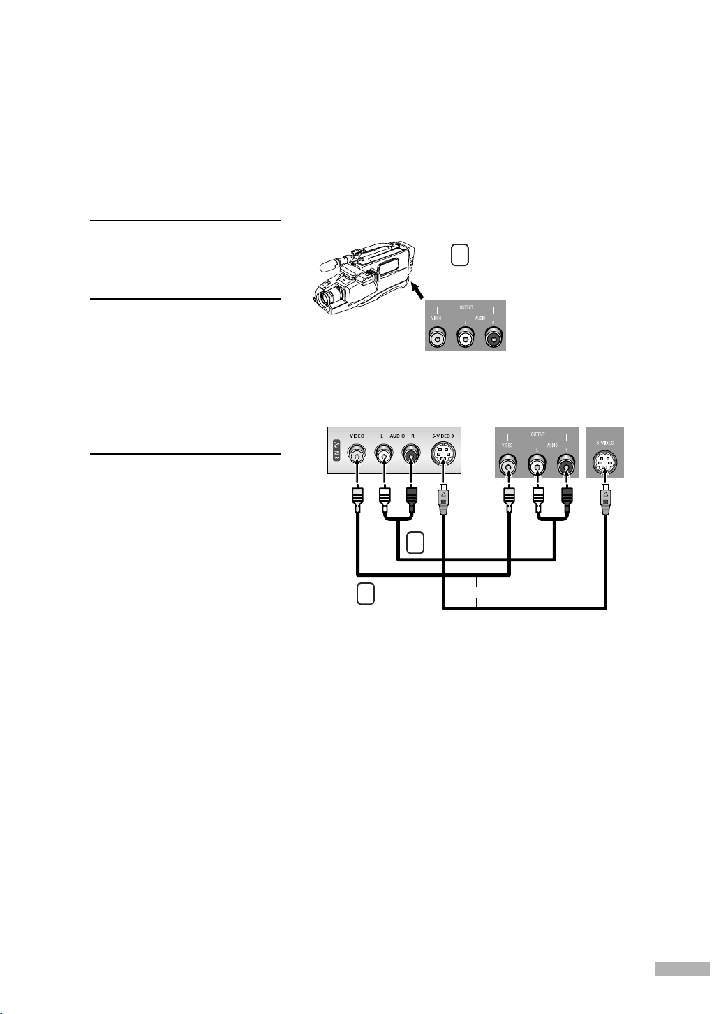
Connecting a Camcorder
The side panel jacks on your TV make it easy to connect a Camcorder to your TV.
You can use your camcorder to view tapes without using a VCR.
Locate the A/V output jacks
on the camcorder. They are
1
usually found on the side or
back of the camcorder.
Connect a set of audio
cables between the AUDIO
2
IN jacks on the TV and the
AUDIO OUT jacks on the
camcorder. If you have a
mono Camcorder, connect
L(mono) to the Camcorder
audio out using only one
audio cable.
Connect a video cable
between the VIDEO IN (or
3
S-VIDEO IN) jack on the TV
and the VIDEO OUT jack
on the Camcorder. The
audio-video cables shown
here are usually included
with a Camcorder. (If not,
check your local electronics
store.) If your Camcorder is
stereo, you need to connect
a set of two cables.
TV Rear of right side
2
3
1
Camcorder
Output Jacks
Camcorder
or
English - 23

Connections
Connecting a DVD Player
The rear panel jacks on your TV make it easy to connect a DVD player to your TV.
Connecting to Y, PB
Connect a set of audio
cables between the
1
COMPONENT (1 or 2)
AUDIO (L, R) IN jacks on
the TV and the AUDIO OUT
jacks on the DVD player.
To enable Component video
viewing, connect a set of
2
video cables between the
COMPONENT (1 or 2)
VIDEO (Y, P
on the TV and VIDEO
B/PR
(Y/P
jacks on the DVD player.
, PR
B
, PR) IN jacks
or Y/CB/CR) OUT
Connecting to Audio and Video Jacks
Connect a set of audio
cables between the AUDIO
1
IN (1 or 2) jacks on the TV
and the AUDIO OUT jacks
on the DVD player.
TV Rear Panel
Incoming
Cable or
Antenna
2
1
DVD Player
TV Rear Panel
Incoming
Cable or
Antenna
Connect a video cable
between the VIDEO IN (1
2
or 2) jack on the TV and the
VIDEO OUT jack on the
DVD player.
NOTE
•For an explanation of
Component video, see your
DVD player’s owner’s
manual.
English - 24
2
DVD Player
1

Connecting a DTV Set-Top Box
Connecting to Y, PB
Connect a set of audio cables
between the COMPONENT (1
1
or 2) AUDIO (L, R) IN jacks on
the TV and the AUDIO OUT
jacks on the Set-Top Box.
Connect a set of video cables
between the COMPONENT (1
2
or 2) VIDEO (Y, P
on the TV and VIDEO (Y/P
or Y/CB/CR) OUT jacks on the
Set-Top Box.
Connect the Video/Audio
cables between the VIDEO or
3
S-VIDEO/AUDIO input jacks
on the TV and VIDEO or
S-VIDEO/AUDIO output jacks
on the Set-Top Box.
Connect a coaxial cable
between the Antenna out
4
terminal (i.e., “ANT.OUT”)
on the Set-Top Box and the
ANT 1 IN (CABLE) on the TV.
, PR
B
, PR) IN jacks
B/PR
Connecting to DVI (Digital Visual Interface)
Connect a set of audio cables
between the DVI AUDIO (L, R)
1
IN jacks on the TV and the
AUDIO OUT jacks on the
Set-Top Box.
4
Incoming
Cable or
Antenna
TV Rear Panel
3
2
1
DTV Set-Top Box
TV Rear Panel
Connect an HDMI/DVI video
cable between the HDMI/DVI
2
IN jack on the TV and the DVI
OUT jack on the Set-Top Box.
Connect the Video/Audio
cables between the VIDEO or
3
S-VIDEO/AUDIO input jacks
on the TV and VIDEO or
S-VIDEO/AUDIO output jacks
on the Set-Top Box.
Connect a coaxial cable
between the Antenna out
4
terminal (i.e., “ANT.OUT”)
on the Set-Top Box and the
ANT 1 IN (CABLE) on the TV.
4
Incoming
Cable or
Antenna
1
2
DTV Set-Top Box
NOTES
• For an explanation of Component video, see your Set-Top Box owner’s manual.
• Requires a Cable Converter.
•To use the TV Guide On Screen
and the G-LINK
TM
cable.
TM
, you have to connect both the Video/Audio cable
3
English - 25

Connections
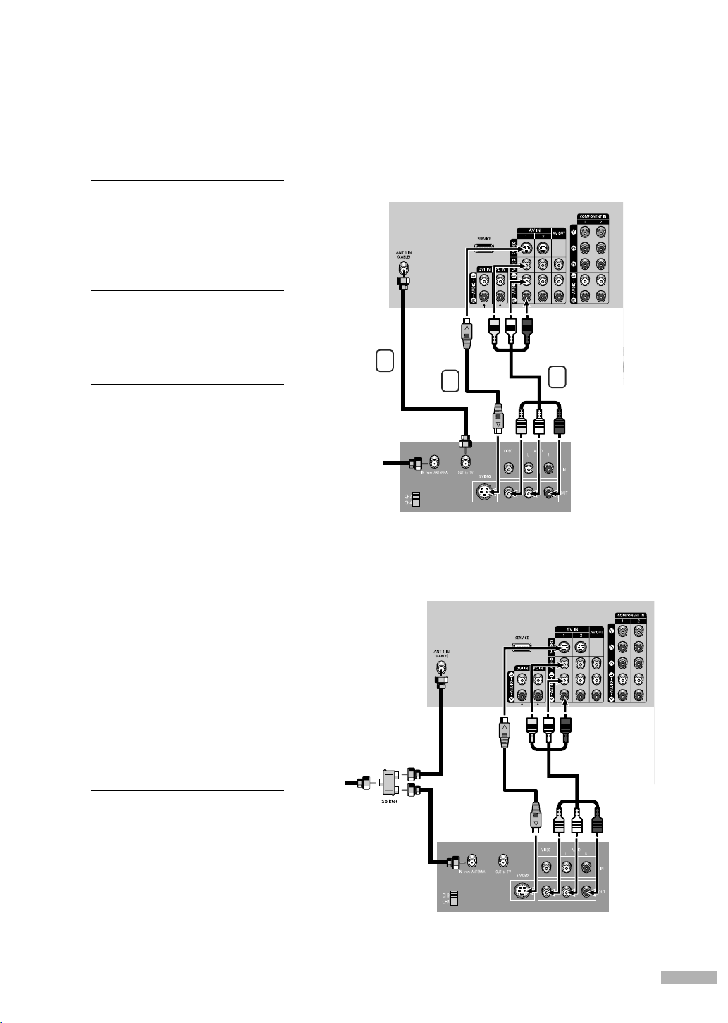
Connecting a VCR and DTV Set-Top Box
Connect the Video/Audio
cables between the VIDEO
1
or S-VIDEO/AUDIO input
jacks on the TV and VIDEO
or S-VIDEO/AUDIO output
jacks on the VCR.
Incoming Cable
or Antenna
TV Rear Panel
Connect the Video/Audio
cables between the VIDEO
2
or S-VIDEO/AUDIO input
jacks on the TV and VIDEO
or S-VIDEO/AUDIO output
jacks on the Set-Top Box.
Use the coaxial cable to
connect between the splitter
3
and the ANT 1 IN (CABLE)
on the TV and between the
splitter and the ANT IN on
the Set-Top Box.
Connect a coaxial cable
between the Antenna in
4
terminal on the VCR and the
Antenna out terminal on the
Set-Top Box.
3
DTV Set-Top Box Stereo VCR
Connecting to HDMI (High Definition Multimedia Interface)
Connect an HDMI cable
between the HDMI/DVI IN
1
jack on the TV and the HDMI
OUT jack on the Set-Top Box.
Connect the Video/Audio
cables between the VIDEO or
2
S-VIDEO/AUDIO input jacks
on the TV and VIDEO or
S-VIDEO/AUDIO output jacks
on the Set-Top Box.
TV Rear Panel
2
1
4
Connect a coaxial cable
between the Antenna out
3
terminal (i.e., “ANT.OUT”)
on the Set-Top Box and the
ANT 1 IN (CABLE) on the TV.
NOTES
•Make sure the HDMI/DVI source’s
power is on, or you will be unable
to select it in the TV menu’s source list.
• For an explanation of Component video,
see your Set-Top Box owner’s manual.
•To use the TV Guide On Screen
to connect both the Video/Audio cable and
the G-LINK
English - 26
TM
cable.
TM
, you have
3
1
2
Incoming
Cable or
Antenna
DTV Set-Top Box

Connecting a Digital Audio System
There are many types of digital audio systems on the market today.
A simplified illustration of an audio system is shown below. For more information, see your
audio system owner’s manual.
If your audio system has an
optical digital audio input,
1
connect to the “DIGITAL
AUDIO OUT(OPTICAL)” jack
on the TV.
NOTE
• OPTICAL: converts the electric
signal into an optical light
signal, and transmits it through
glass fibers. A transmission
system of digital audio in the
form of a light wave, S/PDIF
format using a glass conductor.
See page 80 to set the digital
output format (Dolby Digital or
PCM) appropriate to your
digital audio component.
Connecting to an Analog Amplifier
The “AUDIO OUT” terminals
cannot be used for external
1
speakers. You must hook
them up to an amplifier.
When an audio amplifier is
connected to the “AUDIO
OUT” terminals: Decrease
the gain (volume) of the
audio amplifier, set the
internal mute on in the TV’s
Sound Menu and adjust the
volume level with the volume
control of the amplifier.
TV Rear Panel
Audio System
TV Rear Panel
NOTE
• If using the HDMI/DVI, PC, or
Component input on the TV, the
audio output signal is available
only when the TV’s Internal Mute
is set to on.
(Refer to page 81)
Amplifier
English - 27

SAMSUNG

Operation

Operation
Turning the TV On and Off
Press the POWER button on the remote control.
You can also use the POWER button on the front panel.
Viewing the Menus and On-Screen Displays
The on-screen menu system allows you to control the settings of your TV. Access the on-screen menu
system by pressing the MENU button on the remote control. Once the on-screen menu appears, use
the …/†/œ/√/ENTER buttons on your remote control to select menu items and make adjustments.
You can also view the on-screen menu system and make some adjustments using the TV’s side panel
buttons.
Viewing the Menus
Press the MENU button.
The main menu is displayed.
1
There are six menu groups:
“Input”, “Picture”, “Sound”,
“Channel”, “Setup”, and
“Listings”.
Press the … or † button to
select an item you want
2
in the menu.
Press the œ, √ or ENTER
button to display, change,
or use the selected items.
Use the ENTER button to
enter items in the menu.
Press the EXIT button to exit.
3
Viewing the Display
Press the INFO button on the
remote control.
The TV displays the current
channel, the status of certain
picture and sound settings and
the current time.
The information displayed varies
according to the selected source.
Input
Source List : TV
Edit Name
Picture
Anynet
D-Net
Sound
Channel
Setup
Listings
Input
Mode : Standard
Size : 16:9
Picture
Digital NR : On
DNIe Demo : Off
Sound
My Color Control
Channel
Film Mode : Off
PIP
Setup
Listings
Cable 3
Picture Mode
Sound Mode
MTS
Caption
V-Chip
No Time Information
Input
Move
Enter
Exit
Picture
Move Enter Return
Standard
Custom
Stereo
Off
Off
√
√
√
√
√
√
√
√
√
English - 30
 Loading...