

Samsung HLN4365W1, HLN567W1, HLN437W1, HLN617W1, HLN467W1 User Manual
...
1-800-SAMSUNG (1-800-726-7864)
Samsung Electronics America
Service Division
400 Valley Road, Suite 201
Mount Arlington, NJ 07856
www.samsungusa.com
Samsung Electronics Canada Inc.
Samsung Customer Care
7037 Financial Drive
Mississauga, Ontario
L5N 6R3
www.samsung.ca
BP68-00188A-00
DLPTV
INSTRUCTION MANUAL
HLN467W1/HLN567W1/HLN4365W1/HLN5065W1/HLN437W1
HLN507W1/HLN617W1
DLPTV
2 3
Safety Instructions
Warning! Important
Safety Instructions
CAUTION: TO REDUCE THE RISK OF ELECTRIC SHOCK, DO NOT REMOVE COVER (OR
BACK). THERE ARE NO USER SERVICEABLE PARTS INSIDE. REFER ALL SERVICING
TO QUALIFIED SERVICE PERSONNEL.
This symbol indicates high voltage is present. It is dangerous to make any kind of contact
with any part inside this product.
This symbol alerts you that important literature concerning operation and maintenance has
been included with this product.
CAUTION: FCC/CSA regulations state that any unauthorized changes or modifications to this
equipment may void the user’s authority to operate it.
CAUTION: To prevent electric shock, match the wide blade of plug to the wide slot, and fully
insert the plug.
ATTENTION: Pour eviter les chocs electriques, introduire la lame le plus large de la fiche dans la
borne correspondante de la prise et pousser jusqu’au fond.
Note to CATV system installer: This reminder is provided to call CATV system installer’s attention
to Article 820-40 of the National Electrical Code (Section 54 of Canadian Electrical Code, Part I),
that provides guidelines for proper grounding and, in particular, specifies that the cable ground
shall be connected to the grounding system of the building as close to the point of cable entry as
possible.
Important: One Federal Court has held that unauthorized recording of copyrighted TV programs
is an infringement of U.S. copyright laws. Certain Canadian programs may also be copyrighted
and any unauthorized recording in whole or in part may be in violation of these laws.
To prevent damage which may result in fire or electric shock,
do not expose this appliance to rain or moisture.
CAUTION
RISK OF ELECTRIC SHOCK
DO NOT OPEN
Thank You for Choosing Samsung
Thank you for choosing Samsung! Your new Samsung projection TV represents the latest in Digital Light
Processing television technology. We designed it with easy-to-use on-screen menus and closed captioning
capabilities, making it one of the best products in its class. We are proud to offer you a product that will
provide convenient, dependable service and enjoyment for years to come.
Important Safety Information
Always be careful when using your TV. To reduce the risk of fire, electrical shock, and other injuries, keep
these safety precautions in mind when installing, using, and maintaining your unit.
• Read all safety and operating instructions before operating your TV.
• Keep the safety and operating instructions for future reference.
• Heed all warnings on the TV and in the operating instructions.
• Unplug the TV from the wall outlet before cleaning. Use a damp cloth; do not use liquid or aerosol
cleaners.
• Never add any attachments and/or equipment without approval of the manufacturer. Such additions
can increase the risk of fire, electric shock, or other personal injury.
• Do not use the TV where contact with water is possible, such as near bath tubs, sinks, washing
machines, swimming pools, etc.
• Do not place the TV on an unstable cart, stand, tripod, bracket, or table
where it can fall. A falling TV can cause serious injury to a child or adult,
and serious damage to the appliance. Use only with a cart, stand, tripod,
bracket, or table recommended by the manufacturer or sold with the TV.
Follow the manufacturer’s instructions when mounting the unit, and use a
mounting accessory recommended by the manufacturer. Move the TV and
cart with care. Quick stops, excessive force, and uneven surfaces can
make the unit and cart unsteady and more likely to overturn.
• The TV is designed with slots in the cabinet for ventilation to protect it from overheating. Do not block
these openings with any object, and do not put the TV on a bed, sofa, rug, or other similar surface.
Do not put the TV near a radiator or heat register. If you do put the TV on a rack or bookcase, make
sure that there is adequate ventilation and that you’ve followed the manufacturer’s instructions for
mounting.
• Operate your TV only from the type of power source indicated on the marking label. If you are not sure
of the type of power supplied to your home, consult your appliance dealer or local power company.
• Use only a grounded or polarized outlet. For your safety, this TV is equipped with a polarized
alternating current line plug having one blade wider than the other. This plug will fit into the power
outlet only one way. If you are unable to insert the plug fully into the outlet, try reversing the plug. If the
plug still does not fit, contact an electrician to replace your outlet.
FCC Information
5
Safety Instructions
4
•Protect the power cord. Power supply cords should be routed so that they won’t be walked on or
pinched by objects placed on or against them. Pay particular attention to cords at plugs, convenience
receptacles, and the point where they exit from the unit.
• Unplug the TV from the wall outlet and disconnect the antenna or cable system during a lightning storm
or when left unattended and unused for long periods of time. This will prevent damage to the unit from
lightning and power-line surges.
•Avoid overhead power lines. An outside antenna system should not be placed in the vicinity of
overhead power lines or other electric light or power circuits, or where it can fall into such power lines
or circuits. When installing an outside antenna system, be extremely careful to keep from touching the
power lines or circuits. Contact with such lines can be fatal.
• Do not overload the wall outlet or extension cords. Overloading can result in fire or electric shock.
• Do not insert anything through the openings in the unit, where they can touch dangerous voltage points
or damage parts. Never spill liquid of any kind on the TV.
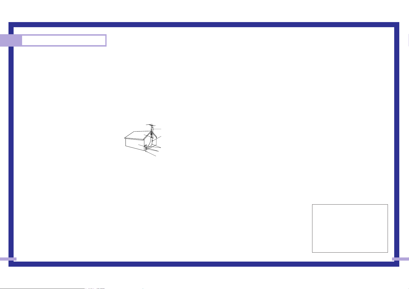
•Ground outdoor antennas. If an outside antenna or cable
system is connected to the TV, be sure the antenna or cable
system is grounded so as to provide some protection against
voltage surges and built up static charges. Section 810 of
the National Electrical Code, ANSI/NFPA No.70-1984,
provides information about proper grounding of the mast
and supporting structure, grounding of the lead-in wire to an
antenna discharge unit, size of grounding conductors,
location of antenna discharge unit, connection to grounding
electrodes, and requirements for the grounding electrode.
• Do not attempt to service the TV yourself. Refer all servicing to qualified service personnel. Unplug the
unit from the wall outlet and refer servicing to qualified service personnel when:
-
The power-supply cord or plug is damaged
-
Liquid has been spilled on the unit or if objects have fallen into the unit
-
The TV has been exposed to rain or water
-
The TV does not operate normally by following the operating instructions
-
The TV has been dropped or the cabinet has been damaged
-
The TV exhibits a distinct degradation in performance
-
When the LAMP(BULB ONLY) replacement procedure on pg. 11 is unsuccessful
• If you make adjustments yourself, adjust only those controls that are covered by the operating
instructions. Adjusting other controls may result in damage and will often require extensive work by a
qualified technician to restore the TV to normal.
• When replacement parts are required, be sure the service technician uses replacement parts specified
by the manufacturer or those that have the same characteristics as the original part. Unauthorized
substitutions may result in additional damage to the unit.
•Upon completion of any service or repairs to this TV, ask the service technician to perform safety checks
to determine that the TV is in a safe operating condition.
User Instructions
The Federal Communications Commission Radio
Frequency Interference Statement includes the
following warning:
NOTE: This equipment has been tested and found
to comply with the limits for a Class B digital
device, pursuant to Part 15 of the FCC Rules.
These limits are designed to provide reasonable
protection against harmful interference in a
residential installation. This equipment generates,
uses, and can radiate radio frequency energy
and, if not installed and used in accordance with
the instructions, may cause harmful interference to
radio communications. However, there is no
guarantee that interference will not occur in a
particular installation .
If this equipment does cause harmful interference
to radio or television receptions, which can be
determined by turning the equipment off and on,
the user is encouraged to try to correct the
interference by one or more of the following
measures:
• Reorient or relocate the receiving antenna.
• Increase the separation between the equipment
and receiver.
• Connect the equipment into an outlet on a circuit
different from that to which the receiver is
connected.
• Consult the dealer or an experienced radio/TV
technician for help.
User Information
Changes or modifications not expressly approved
by the party responsible for compliance could
void the user’s authority to operate the equipment.
If necessary, consult your dealer or an
experienced radio/television technician for
additional suggestions. You may find the booklet
called How to Identify and Resolve Radio/TV
Interference Problems helpful. This booklet was
prepared by the Federal Communications
Commission. It is available from the U.S.
Government Printing Office, Washington, DC
20402, Stock Number 004-000-00345-4.
The party responsible for product compliance:
SAMSUNG ELECTRONICS CO., LTD
America QA Lab of Samsung
3351 Michelson Drive,
Suite #290, Irvine, CA92612 USA
Warning
User must use shielded signal interface cables to
maintain FCC compliance for the product.
Provided with this monitor is a detachable power
supply cord with IEC320 style terminations.
It may be suitable for connection to any UL Listed
personal computer with similar configuration.
Before making the connection, make sure the
voltage rating of the computer convenience outlet
is the same as the monitor and that the ampere
rating of the computer convenience outlet is equal
to or exceeds the monitor voltage rating. For 120
Volt applications, use only UL Listed detachable
power cord with NEMA configuration 5-15P type
(parallel blades) plug cap. For 240 Volt
applications use only UL Listed Detachable power
supply cord with NEMA configuration 6015P type
(tandem blades) plug cap.
IC Compliance Notice
This Class B digital apparatus meets all
requirements of the Canadian Interference-Causing
Equipment Regulations.
Notice de Conformité IC
Cet appareil numérique de classe B respecte
toutes les exigences du Règlement sur les
équipements produisant des interférences au
Canada.
This Class B digital apparatus complies with
Canadian ICES-003.
Cet appareil numéique de la classe B est
conforme à la norme NMB-003 du Canada.
This device complies with part 15 of the FCC
Rules. Operation is subject to the following two
conditions:
(1) This device may not cause harmful
interference, and
(2) This device must accept any interference
received, including interference that may
cause unesired operation.
This television receiver provides display of
television closed captioning in accordance with
§15.119 of the FCC rules.
EXAMPLE OF
ANTENNA GROUNDING
GROUND CLAMP
ELECTRIC
SERVICE
EQUIPMENT
NEC — NATIONAL ELECTRICAL CODE
ANTENNA
LEAD IN WIRE
ANTENNA
DISCHARGE UNIT
(NEC SECTION 810-20)
GROUNDING
CONDUCTORS
(NEC SECTION 810-21)
GROUND CLAMPS
POWER SERVICE GROUNDING
ELECTRODE SYSTEM
(NEC ART 250, PART H)

Special Features ...............................................................................................50
Setting Up Your Remote Control .............................................................................50
Remote Control Codes..........................................................................................53
Fine Tuning Channels ...........................................................................................54
LNA (Low Noise Amplifier)....................................................................................55
Selecting the Color Tone .......................................................................................56
Setting the Film Mode...........................................................................................56
DNIeTM(Digital Natural Image engine) ...........................................................57
Digital Noise Reduction ........................................................................................58
Setting the Blue Screen Mode................................................................................59
Changing the Screen Size.....................................................................................60
Special Audio Options .........................................................................................61
MTS Settings: Choosing a Soundtrack ........................................................61
Virtual Dolby ...........................................................................................62
BBE ........................................................................................................63
Auto Volume............................................................................................64
Setting The On/Off Melody ..................................................................................65
Viewing Closed Caption Information ......................................................................66
Viewing Picture-in-Picture.......................................................................................67
Selecting a PIP Screen ..............................................................................67
Selecting an External Signal ......................................................................68
Selecting a Signal Source (Antenna or Cable) for PIP...................................69
Swapping the Contents of the PIP and Main image......................................70
Changing the Size of the PIP image ...........................................................71
Changing the Location of the PIP Image......................................................72
Changing the Picture-in-Picture Channel ......................................................73
Selecting the Sound Source .......................................................................74
Using the V-Chip..................................................................................................75
PC Display.......................................................................................................82
Using Your TV as a Computer (PC) Display .............................................................82
How to connect Your PC to the TV .............................................................82
How to Set up Your PC Software (Windows only) ........................................83
Display Modes.........................................................................................84
How to Set up Your TV as a PC display ..................................................................85
Picture Quality Adjustment ....................................................................................86
Changing the Position of the Image (Moving left, right, up and down) .......................88
Changing the Screen Size (PC mode).....................................................................90
Appendix.........................................................................................................94
Troubleshooting ...................................................................................................94
Care and Maintenance.........................................................................................95
Using Your TV in Another Country..........................................................................95
Specifications ......................................................................................................95
7
Your New Wide TV ..........................................................................................10
Replacing the Lamp..............................................................................................10
List of Features .....................................................................................................12
Checking Parts.....................................................................................................12
Side Panel Buttons................................................................................................13
Side Panel Jacks ................................................................................................. 13
Front Panel LED Indicators .....................................................................................14
Rear Panel Jacks ..................................................................................................15
Remote Control ....................................................................................................16
Installing Batteries in the Remote Control.....................................................17
Connections .....................................................................................................20
Connecting VHF and UHF Antennas.......................................................................20
Antennas with 300-ohm Flat Twin Leads .....................................................20
Antennas with 75-ohm Round Leads...........................................................20
Separate VHF and UHF Antennas ..............................................................21
Connecting Cable TV and VCR..............................................................................22
Cable without a Cable Box .......................................................................22
Cable with a Cable Box that Descrambles All Channels ...............................22
Connecting a Cable Converter Box............................................................23
Connecting a Cable Converter Box and a VCR ...........................................23
Connecting a Camcorder......................................................................................24
Connecting a DVD Player .....................................................................................25
Connecting to Y,PB,PR ..............................................................................25
Connecting to audio and video jacks .........................................................25
Connecting a DTV Set Top Box ..............................................................................26
Connecting to Y,PB,PR ..............................................................................26
Connecting to DVI (Digital Visual Interface) .................................................26
Connecting to R,G,B.................................................................................27
Operation........................................................................................................30
Turning the TV On and Off....................................................................................30
Viewing the Menus and Displays ...........................................................................30
Selecting the Menu Language................................................................................31
Selecting the Antenna Input...................................................................................31
Channel Memory .................................................................................................33
Changing Channels..............................................................................................34
Selecting Your Favorite Channels ...........................................................................35
Scanning Channels ..............................................................................................36
Labeling the Channels ..........................................................................................37
Picture Control .....................................................................................................38
Sound Control .....................................................................................................40
Setting the Clock..................................................................................................42
Setting the Timers.................................................................................................43
Viewing an External Signal Source ........................................................................46
Table of Contents
6

Your New Wide TV
SAMSUNG
Your New Wide TV
10
• For replacement, you will need a 5.91 Inches-long Phillips screwdriver and a pair of gloves.
Replacing the Lamp
•Why do I need to replace the lamp?
The lamp used in a projection TV has a limited lifespan. For the best screen quality it needs to be
replaced periodically.
After replacing the lamp, the screen quality will be bright and clear as new.
•When do I need to replace it?
It should be replaced when the screen becomes darker, less clear or when all three LEDs on the front
(Timer, Lamp, & Temp.) are flashing.
• Check before lamp replacement
1. The lamp must be the same code number and type.
2. The lamp type is indicated on the right side of the TV. It is also indicated on the lamp case.
3. After checking the code number for the lamp, give the code number to the store where you
purchased the TV or to a Samsung Service center.
•Caution
1. Replace with the correct code numbered lamp to avoid damage to the TV.
2. Turn the power off and wait for 30 minutes before replacing the lamp as it will be hot.
3. Do not touch the glass part of the lamp with your bare hands nor insert any foreign object inside
the cover as it may cause poor screen quality, electric shock or fire.
4. Do not place the old lamp near flammable objects or within the reach of children.
… HLN437W1/HLN507W1
HLN617W1/HLN4365W1
HLN5065W1
… HLN467W1/HLN567W1
… HLN437W1/HLN507W1
HLN617W1/HLN4365W1
HLN5065W1
… HLN467W1/HLN567W1
NOTES
• Be sure the replacement Lamp is the same type.
• After replacing the lamp, align the lamp cover with the groove and secure the screw.
• The TV will not turn on if the lamp cover is not correctly closed (as this will activate the
protective circuit).
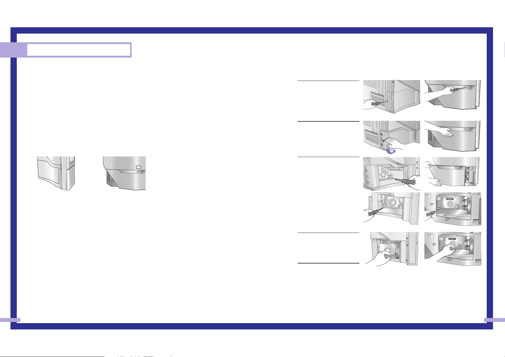
1
Unplug TV, then use a
screwdriver to remove the
screw as shown in the
picture.
(HLN467W1/HLN567W1:
Remove the rubber cap
and unscrew the screw.)
2
Remove the Lamp cover.
(HLN467W1/HLN567W1:
Exert a bit of force to the
right and pull for easy
opening.)
3
Use a screwdriver to
remove the screws
securing the Lamp. There
are 2 screws: one on the
left and one on the right.
When the screws have
been completely
unfastened, they will still
be connected to the body
of the Lamp.
4
Separate the Lamp from
the engine by holding the
handle and pulling it out.
5
To reinstall the Lamp,
follow these steps in
reverse order.
11
1312
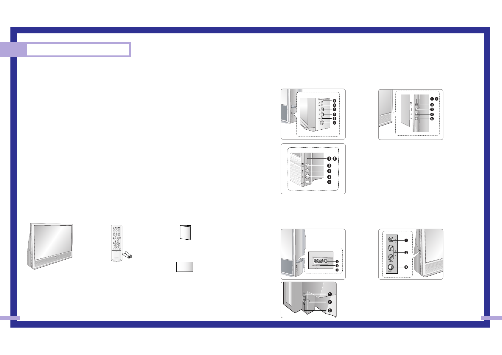
Side Panel Buttons
The buttons on the side panel control your TV’s basic features, including the on-screen menu system.
To use the more advanced features, you must use the remote control.
Side Panel Jacks
Use the side panel jacks to connect a component that is used only occasionally (a camcorder or video
game, for example).
List of Features
Your TV was designed and engineered using the latest technology. It is a full-featured, high-performance
unit that exceeds industry standards. In addition, it has these special features:
• Easy-to-operate remote control
• Easy-to-use on-screen menu system you can access from the side panel or remote control
• Automatic timer to turn the TV on and off at any time you choose
• Adjustable picture and sound settings and the ability to memorize your favorite settings
• Automatic channel tuning for up to 181 channels
• A special filter to reduce or eliminate reception problems
• Fine tuning control for the sharpest picture possible
• A built-in multi-channel sound decoder for stereo and bilingual listening
• Built-in, dual channel speakers
• A special sleep timer
• Picture-in-Picture capability that lets you watch two channels at once
• Widescreen TV with adjustable image size
• Life-like clear images provided by DNle technology
Checking Parts
Once you have unpacked your TV, check to make sure that you have all the parts shown here.
If any piece is missing or broken, call your dealer.
Your New Wide TV
This Manual
Television
Remote Control
(BP59-00048A)/
AAA Batteries
(4301-000121)
Warranty Card
Œ
TV/VIDEO
Press to switch between viewing TV programs and signals from connected
components.
´
MENU
Press to see the on-screen menu.
ˇ
▼ CH ▲
Press to change channels and move between items on the on-screen menu.
¨
VOL +, –
Press to lower or raise the volume and to select items when using the onscreen menu.
ˆ
ENTER
Press to activate (or change) a particular item.
Ø
POWER
Press to turn the TV on and off.
Œ
VIDEO Input jack
Connect the video signal from a camcorder or video game.
´
AUDIO Input jacks
Connect the audio signal from a camcorder or video game.
ˇ
S-VIDEO Input jack
Connect an S-video signal from a camcorder or video game.
(S-Video 3 jack and Audio L/R input 3 are used in conjunction.)
œ HLN507W1
œ HLN617W1
œ HLN5065W1
œ HLN467W1
œ HLN567W1
œ HLN467W1
œ HLN567W1
œ HLN437W1
œ HLN4365W1
œ HLN617W1
œ HLN437W1
œ HLN507W1
œ HLN4365W1
œ HLN5065W1
15
Your New Wide TV
14
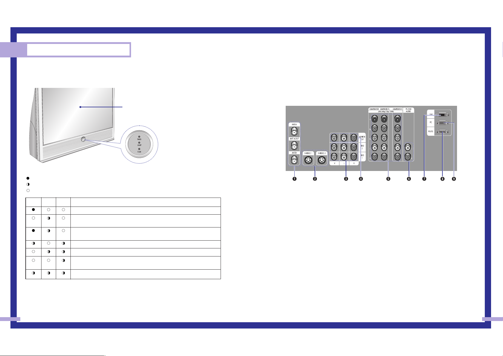
Front Panel LED Indicators
The three lights on the front panel indicate the status of your TV.
: Light is On
: Light is Blinking
: Light is Off
• It takes about 30 seconds for the TV to warm up, so normal brightness may not appear immediately.
• The TV has a fan to keep the inside lamp from overheating. You’ll occasionally hear it working.
Timer Lamp Temp
Indication
Auto Timer ON/OFF has been set.
Standby state.
The picture will automatically appear in about 25 seconds.
Auto Timer ON/OFF has been set and the set will automatically be turned on in
about 25 seconds.
A cooling fan inside the set is not operating normally.
Lamp cover on rear of the set is not properly shut.
Check if the ventilation hole on the rear of the set is blocked, because if the
inner temperature is too high, the power will shut off.
Lamp may be defective. Please contact a certified technician.
Rear Panel Jacks
Use the rear panel jacks to connect components such as a VCR. You can connect different components
such as VCRs, Set-Top Box and a DVD player etc., because there are two sets of video input jacks and
three set of component video input jacks on the rear panel of your TV. For more information, please see
“Connections”.
Œ
ANTENNA terminals
Two independent cables or antennas can be connected to these
terminals. Use ANT-A and ANT-B terminals to receive a signal from
VHF/UHF antennas or your cable system. Use the ANT A-OUT
terminal to send the signal being received by the ANT-A terminal out
to another component (such as a Cable Set Top Box).
The PIP channel can be received only when a signal source is
connected to ANT-A.
´
S-VIDEO INPUT jacks
Connects an S-Video signal from an S-VHS VCR or DVD player.
ˇ
VIDEO/AUDIO INPUT jacks(VCR1, VCR2)
Connect video/audio signals from external sources, such as a VCR or
DVD players.
¨
VIDEO/AUDIO MONITOR OUTPUT jacks
Sends a video signal from the TV to an external source, such as a
VCR.
Note: Monitor Out is available only in RF, Video and S-Video modes.
ˆ
Component1, 2, 3 jacks (Y, PB, PR, L, R)
Use these jacks to connect the component video/audio signals from a
DVD player or a set top box when using the component video input
jacks.
Ø
PC/DVI AUDIO INPUT jacks
Connect these to the audio-output jacks on your PC or set top box.
∏
DVI (Digital Video Interface) jack
Receives the digital signals from a set top box or PC etc.
”
RS-232 jack
The RS232 jack is for repair and software upgrades.
’
PC VIDEO INPUT jack
Connect to the video output port on your PC.
Remote Control Sensor
Aim the remote control towards this spot on the TV.
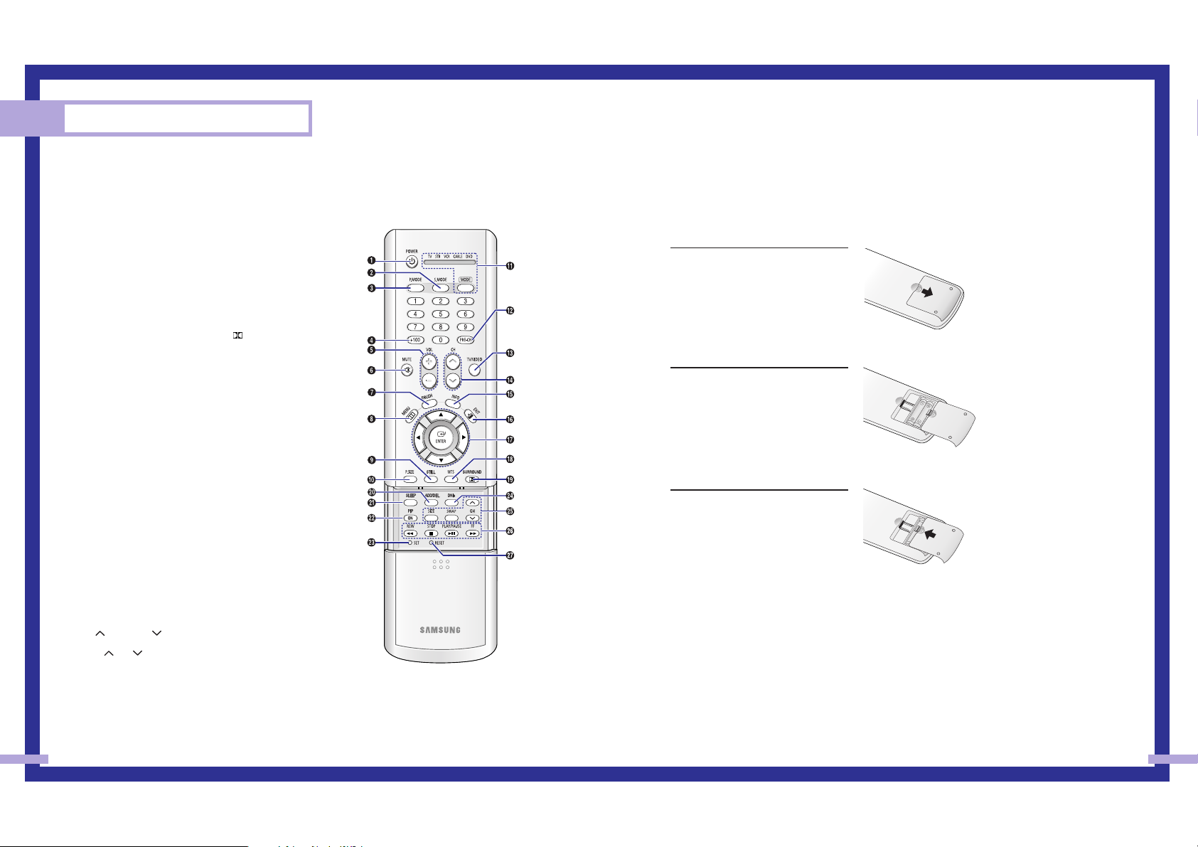
Installing Batteries in the Remote Control
With normal use, the batteries in the remote control should last about a year. If you notice a performance
degradation while using the remote, the batteries may need to be replaced. Make sure you replace both
batteries and do not mix old and new batteries in the remote control. If you won’t be using the remote
control for a long time, remove the batteries and store them in a cool dry place.
1
Slide the back cover all the way out
to open the battery compartment of
the remote control.
2
Install two AAA size batteries.
Make sure to match the “+” and
“–” ends of the batteries with the
diagram inside the compartment.
3
Slide the cover back into place.
17
Remote Control
You can use the remote control up to a distance of about 23 feet from the TV. When using the remote,
always point it directly at the TV. The remote control can also operate your Set Top Box, VCR, cable box,
and DVD player.
Your New Wide TV
16
1. POWER
Turns the TV on and off.
2. S.MODE
Adjust the TV sound by selecting one of the
preset factory settings (or select your personal,
customized sound settings.)
3. P.MODE
Adjust the TV picture by selecting one of the
preset factory settings (or select your personal,
customized picture settings.)
4. +100
Press to select cable channels over 100 on TV.
5. VOL -, VOL +
Press to increase or decrease the volume.
6. MUTE
Press to mute the TV sound.
7. FAV.CH (Favorite Channel)
Press to switch between your favorite channels.
8. MENU
Displays the main on-screen menu.
9. STILL
Press to stop the action during a particular
scene. Press again to resume normal video.
10. P.SIZE
Press to change the screen size.
11. MODE
Selects a target device to be controlled by the
Samsung remote control (i.e., TV, VCR, Cable, or
DVD).
12. PRE-CH
Tunes to the previous channel.
13. TV/VIDEO
Press to display all of the available video
sources (i.e., TV, STB, VCR, DVD, DTV, PC).
14. CH and CH
(Channel Up/Down)
Press CH or CH to change channels.
15. INFO
Press to display information on the TV screen.
16. EXIT
Press to exit the menu.
17. UP, Down, Left, Right
(▲, ▼, œ, √)/ENTER
Press to select highlight up, down, left, or right.
While using the on-screen menus, press ENTER
to activate (or change) a particular item.
18. MTS(Multichannel
Television Stereo)
Press to choose stereo, mono or Separate Audio
Program (SAP broadcast).
19. SURROUND
Press to hear the Dolby surround effect.
20. ADD/DEL
Press to add or erase channels in the TV’s
memory.
Use the ADD/DEL button to memorize/erase
the fine tuning after fine tuning channels.
21. SLEEP
Press to select a preset time interval for
automatic shutoff.
22. PIP
Activates picture in picture.
23. SET
Used during set up of this remote control, so
that it will work compatibly with other devices
(VCR, STB, cable box, DVD, etc.)
24. DNIe
Activates DNIe (Digital Natural Image engine).
25. PIP controls
SWAP; Exchanges the video signal that is
currently displayed on the main screen with the
signal in the PIP window.
SIZE; Press to make the PIP window larger or
smaller.
CH(PIP); Displays the available channels in
sequence. (These buttons change channels in
the PIP window only.)
26. VCR controls
Controls VCR tape functions: Rewind, Play, Fast
Forward, Stop, Pause.
27. RESET
If your remote control is not functioning
properly, take out the batteries and press the
reset button for about 2~3 seconds. Re-insert
the batteries and try using the remote control
again.

Connections
SAMSUNG
20 21
Connections
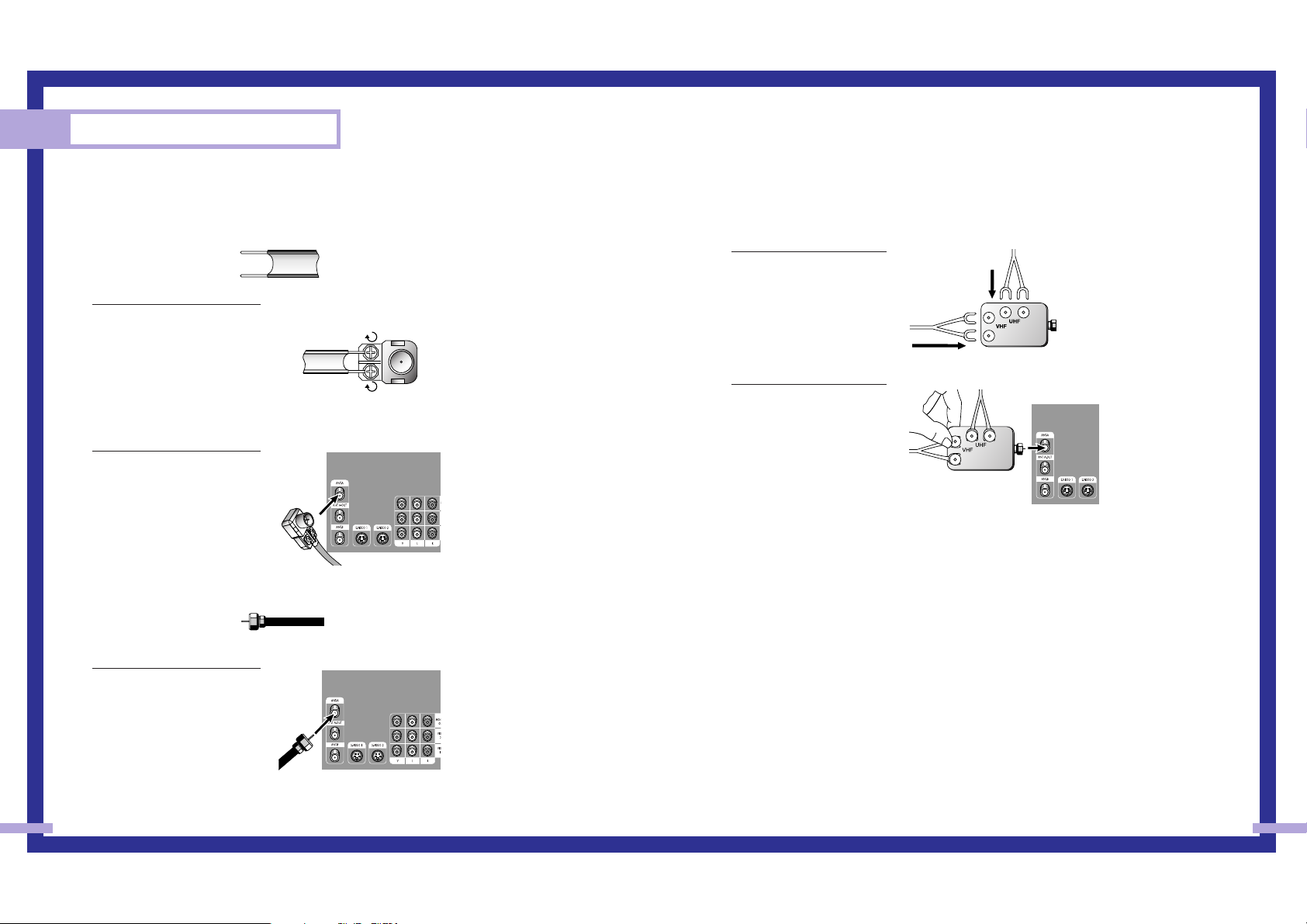
Connecting VHF and UHF Antennas
If you do not have a cable system, you will need to connect an antenna to your TV.
Antennas with 300-ohm Flat Twin Leads
If your antenna looks like this: it has 300-ohm flat twin leads.
1
Place the wires from the twin
leads under the screws on the
300-75 ohm adapter. Use a
screwdriver to tighten the
screws.
2
Plug the adapter into the
ANT-A terminal on the back
panel of the TV.
Antennas with 75-ohm Round Leads
If your antenna looks like this: it is an antenna with 75-ohm round leads.
1
Plug the antenna lead into the
ANT-A terminal on the back
panel of the TV.
Separate VHF and UHF Antennas
If you have two separate antennas for your TV (one VHF and one UHF), you must combine the
two antenna signals before connecting them to the TV. This requires a combiner attachment, which
you can buy at an electronics store.
1
Connect both antenna
leads to the combiner.
2
Plug the combiner into the
ANT-A terminal on the
back panel of the TV.
23
Connections
22
Connecting Cable TV and VCR
You can connect different cable systems to your TV, including cable without a cable box, and
cable with a cable box that descrambles some or all channels.
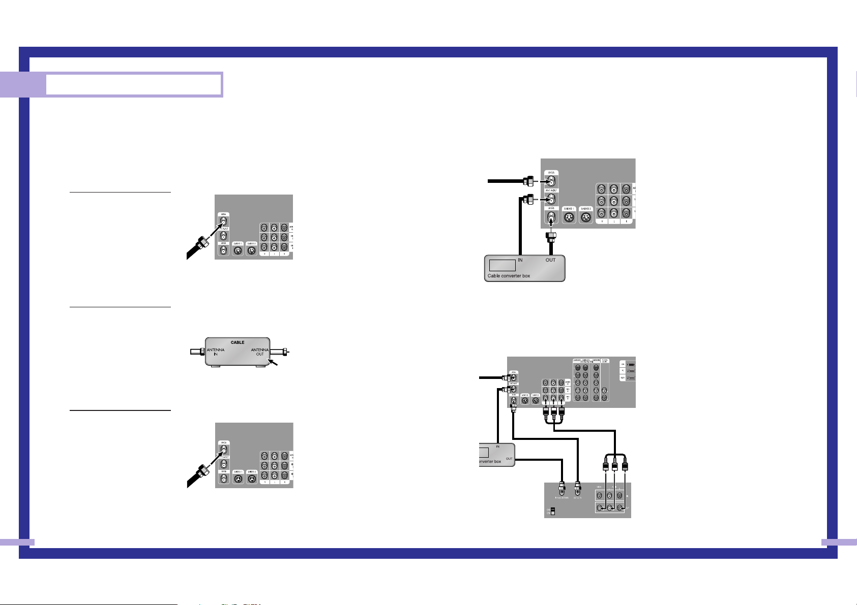
Cable without a Cable Box
If you want to connect cable, and you do not need to use a cable box:
1
Plug the incoming cable
into the ANT-A terminal on
the back of the TV.
Cable with a Cable Box that Descrambles All Channels
1
Find the cable that is
connected to the
ANTENNA OUT terminal
on your cable box. This
terminal might be labeled
“ANT OUT”, “VHF OUT”
or simply, “OUT”.
2
Connect the other end of
this cable to the ANT-A
terminal on the back of the
TV.
Connecting a Cable Converter Box
This connection allows you to watch cable and premium channels. You should keep your TV
selected to ANT-A so that you can use the TV features. When viewing premium channels, select
ANT-B and tune the TV to channel 3 or 4 (whichever channel is vacant in your area), then use the
converter box to change channels. You will need two coaxial cables.
Note: When you use a converter box with
your TV, there may be features that you can
not program using the remote control, such
as programming your favorite channels and
blocking channels.
Connecting a Cable Converter Box and a VCR
This connection allows you to watch and record basic and premium cable channels, as well as
watch videotapes. You should keep your TV selected to ANT-A so that you can use the TV’s
features. When viewing premium channels or recording with the VCR, select ANT-B (whichever
channel is vacant in your area), then use the converter box to change channels.
Caution: If you want to record one channel
while watching another channel, a splitter
(not included) must be added between the
cable and ANT-A. One output of the splitter
goes to ANT-A and the second output is
connected to IN on the cable converter
box.
If you have a mono VCR, connect L/Mono
to VCR Audio OUT using only one audio
cable.
If you have a S-VHS VCR, use the S-video
connections and remove the video cable.
Do not connect the video cable and the
S-video cable to video1 simultaneously.
When you use a converter box with your
TV there may be features that you can not
program using the remote control, such as
programming your favorite channels and
blocking channels.
From Cable
TV Rear Panel
From
Cable
Stereo VCR
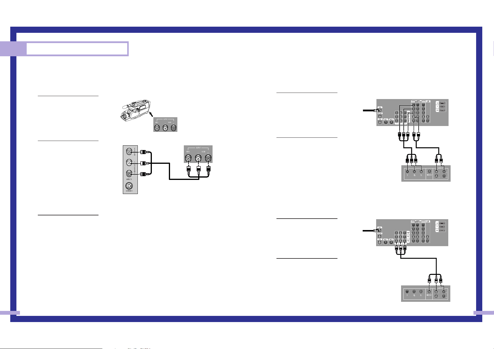
Connecting a DVD Player
The rear panel jacks on your TV make it easy to connect a DVD player to your TV.
Connecting to Y,PB,PR
1
Connect a set of audio
cables between the
Component (1, 2 or 3)
AUDIO IN jacks on the TV
and the AUDIO OUT jacks
on the DVD player.
2
To enable Component video
viewing, connect video
cables between the
Component (1, 2 or 3) Y, P
B
and PRjacks on the TV and
Y, PBand PR(or Y, CB, CR)
output jacks on the DVD
player.
Note: For an explanation of
Component video, see your
DVD player's owner's
manual.
Connecting to audio and video jacks
1
Connect a set of audio
cables between the AUDIO
IN jacks on the TV and the
AUDIO OUT jacks on the
DVD player.
2
Connect video cables
between the VIDEO OUT
jack on the DVD player and
the VIDEO IN jack on the
TV.
25
Connecting a Camcorder
The side panel jacks on your TV make it easy to connect a camcorder to your TV.
You can use your camcorder to view tapes without using a VCR.
1
Locate the A/V output jacks
on the camcorder. They are
usually found on the side or
back of the camcorder.
2
Connect an audio cable
between the AUDIO
OUTPUT jack on the
camcorder and the AUDIO
terminals on the side of the
TV. If your camcorder is
stereo, you must connect
two separate cables.
(The audio cables are
usually included with the
camcorder.)
3
Connect a video cable
between the VIDEO
OUTPUT jack on the
camcorder and the VIDEO
terminal on the side of the
TV. (A video cable is usually
included with the
camcorder.) To watch a
tape, follow your camera’s
instructions and the section
on “Viewing an External
Signal Source” in this
manual.
Connections
24
Camcorder
Output Jacks
TV Side Panel Camcorder
TV Rear Panel
DVD Player
Incoming
Cable or
Antenna
TV Rear Panel
DVD Player
Incoming
Cable or
Antenna
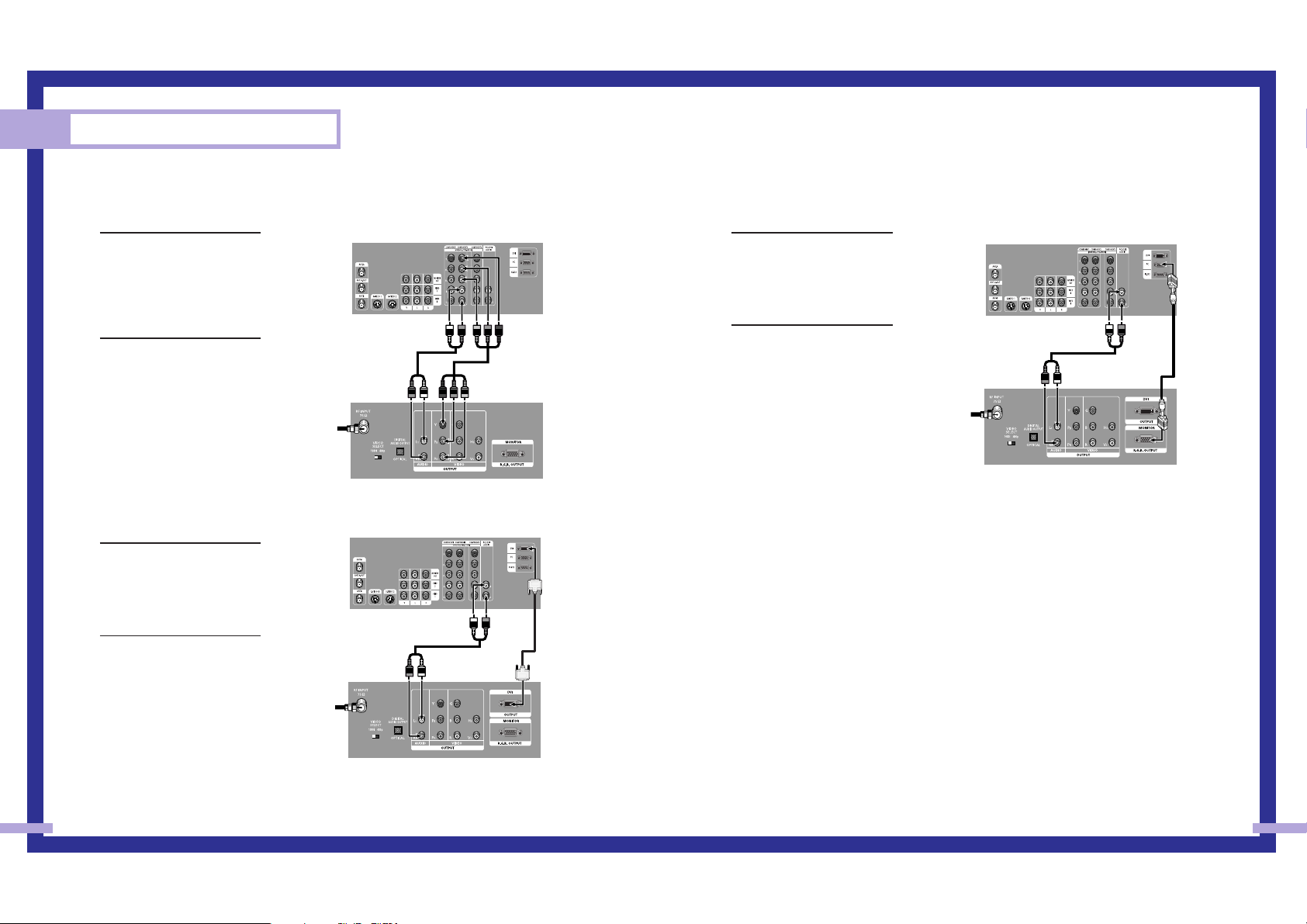
Connecting a DTV Set Top Box
Connecting to Y,PB,PR
1
Connect a set of audio
cables between the
Component (1, 2 or 3)
AUDIO IN jacks on the TV
and the AUDIO OUT jacks
on the Set Top Box.
2
Connect video cables
between the Component (1,
2 or 3) Y, P
B
and PRinputs
on the TV and Y, PBand P
R
(or Y, CB, CR) outputs on the
Set Top Box.
Note: For an explanation of
Component video, see your
Set Top Box owner's
manual.
Connecting to DVI (Digital Visual
Interface)
1
Connect a set of audio
cables between the PC/DVI
AUDIO IN jacks on the TV
and the AUDIO OUT jacks
on the Set Top Box.
2
Connect video cables
between the DVI IN jack on
the TV and the DVI OUT
jack on the Set Top Box.
27
Connections
26
Connecting to R,G,B
1
Connect a set of audio
cables between the PC/DVI
AUDIO IN jacks on the TV
and the AUDIO OUT jacks
on the Set Top Box.
2
Connect video cables
between the PC IN jack on
the TV and the R.G.B OUT
jack on the Set Top Box.
TV Rear Panel
DTV Set Top Box
Incoming
Cable or
Antenna
TV Rear Panel
DTV Set Top Box
Incoming
Cable or
Antenna
TV Rear Panel
DTV Set Top Box
Incoming
Cable or
Antenna

Operation
SAMSUNG
 Loading...