

Page 1

LED TV
Installation manual
imagine the possibilities
Thank you for purchasing this Samsung
product. To receive more complete service,
please register your product at
www.samsung.com/register
Model Serial No.
Page 2

Figures and illustrations in this User Manual are provided for reference only and may differ from actual product appearance.
Product design and specifications may be changed without noticve.
Instruction
This TV is provided with interactive functionality through a set-back box (SBB/STB) connected to the TV, and with other TVs in a computercontrolled system for hotels and other hospitality businesses.
Interactive : When the TV is powered-up initially, it sends a command to identify the SBB/STB; if identified, theTV switches to ONLINE mode
Stand-Alone: If SBB/STB is not identified, the TV should be switched to STAND-ALONE mode with restricted operation.
and full control is through the SBB/STB.
If the TV is in ONLINE mode, it stops receiving IR(Samsung remote) commands and acts according to interface protocol.
Operational Modes
When this TV (in Hotel mode) is operated with a SBB/STB, it is in one of two states:
ONLINE or STAND-ALONE. In the STAND-ALONE state, the TV will act as a Hotel TV, but without active communication. This is to prevent
guests from trying to cheat the system by disconnecting the SBB/STB.
Power
ON
Hotel Mode On
Hotel TV
SBB/STB Online if
one success within 10
attempts
consecutive
SBB/STB
Online-10
fails
Stand-alone
Mode
SBB/STB
StatusAttempt
every 2secs
Online Mode
Poll Rate 20/sec
To set the details for Stand-alone or interactive mode, refer to pages "Setting the hotel option data : Stand-alone mode and Interactive mode"
Some operations may be restricted to prevents guests from "cheating" the TV system.
No main menu (Interactive mode) or Channel Menu, Plug & Play in Main Menu (Stand-Alone mode)
Limited Volume and Panel key lock or unlock
Still image warning
Avoid displaying still images (like jpeg picture files) or still image element (like TV Program logo, panorama or 4:3 image format, stock or news
bar at screen bottom etc.) on the screen. Constant displaying of still picture can cause uneven wear of screen phosphor, which will affect image
quality. To reduce risk of this effect, please follow below recommendations:
Avoid displaying the same TV channel for long periods.
Always try do display any image on full screen, use TV set picture format menu for best possible match.
Reduce brightness and contrast values to minimum required to achieve desired picture quality, exceeded values may speed up the burnout
process.
Frequently use all TV features designed to reduce image retention and screen burnout Refer to the relevant user manual section for details.
Securing the Installation Space
Keep the required distances between the product and other objects (e.g. walls) to ensure proper ventilation.
Failing to do so may result in fire or a problem with the product due to an increase in the internal temperature.
When using a stand or wall-mount, use parts provided by Samsung Electronics only.
Using parts provided by another manufacturer, it may result in a problem with the product or injuries due to the product falling.
The appearance may differ, depending on the product.
Installation with a stand. Installation with a wall-mount.
4 inches
4 inches4 inches
4 inches
4 inches4 inches
4 inches
Page 3

Contents
y Instruction ................................................................................................................................................ 2
y Operational Modes .................................................................................................................................. 2
y Still image warning ................................................................................................................................... 2
y Securing the Installation Space ................................................................................................................ 2
y Accessories ............................................................................................................................................. 4
y Installing the LED TV Stand ...................................................................................................................... 5
y Viewing the Connection Panel .................................................................................................................. 9
y Door Eye .................................................................................................................................................. 13
y TV Controller ............................................................................................................................................ 14
y Viewing the Remote Control ..................................................................................................................... 15
y Using the Smart Touch Control ................................................................................................................ 17
y Connecting to the Network ...................................................................................................................... 22
y Connecting the TV with SBB .................................................................................................................... 26
y Connecting the Bathroom Speakers ........................................................................................................ 28
y Connecting the MediaHub HD ................................................................................................................. 32
y Connecting the RJP (Remote Jack Pack) ................................................................................................. 34
y Setting the Hotel Option Data .................................................................................................................. 37
y SIRCH ..................................................................................................................................................... 52
y Installing the Wall Mount .......................................................................................................................... 53
y Securing the TV to the Wall ...................................................................................................................... 54
y Anti-theft Kensington Lock ....................................................................................................................... 54
y Specifications .......................................................................................................................................... 55
ENGLISH
English
3
Page 4

Accessories
− The provided accessories may vary depending on the model.
y Remote Control & Batteries (AAA x 2)
y Smart Touch Control&Batteries (AA x 2)
(Only HC890/HC890V model)
y Quick Set up Guide
y Hotel Mount Kit (40/48 inch include)
y Holder-Ring (Not available in some inches)
− The stand and stand screw may not be included, depending on the model.
y Power Cord
y Safety Guide (Only HONG KONG)
y Service Card / Warranty Card / Flyer (Only CHINA)
y Holder-Wire Stand
y 3D Glasses Guide (Except HC690 40/48 inch model)
4
English
Page 5

Installing the LED TV Stand
O
X
y HG690 Model
y Stand Components
When installing the stand, use the provided components and parts.
40~65 inch
75 inch
A
or
A
B
B
X4(M4 X L12)
1 - 1 1 - 2
40/48 inch:
M4 X L12
Front
A
ATTENTION
DO NOT USE
CHEMICALS
B
DO NOT USE
GREASE
C
(M4 X L12)
DO NOT USE
OIL
x4
Top View
Side
or
60/65 inch:
M4 X L10
B
A
Rear
C
(M4 X L10)
Front
×8(M4×L12, for inch 40 48)
C
×8(M4×L10, for inch 60” 65”)
x4
Top View
ATTENTION
DO NOT USE
DO NOT USE
CHEMICALS
GREASE
or
DO NOT USE
OIL
2 3
− Place a sof t cloth over a table to protect the TV, and then
place the TV on the cloth screen side down.
− Insert the Stand Guide into the slot on the bottom of the TV.
English
5
Page 6
4
HG40AC690
HG48AC690
HG60AC690
HG65AC690
HG75AC690
C
C
(M4 X L10)
C
(M4 X L12)
x4
(M4 X L12)
x4
x4
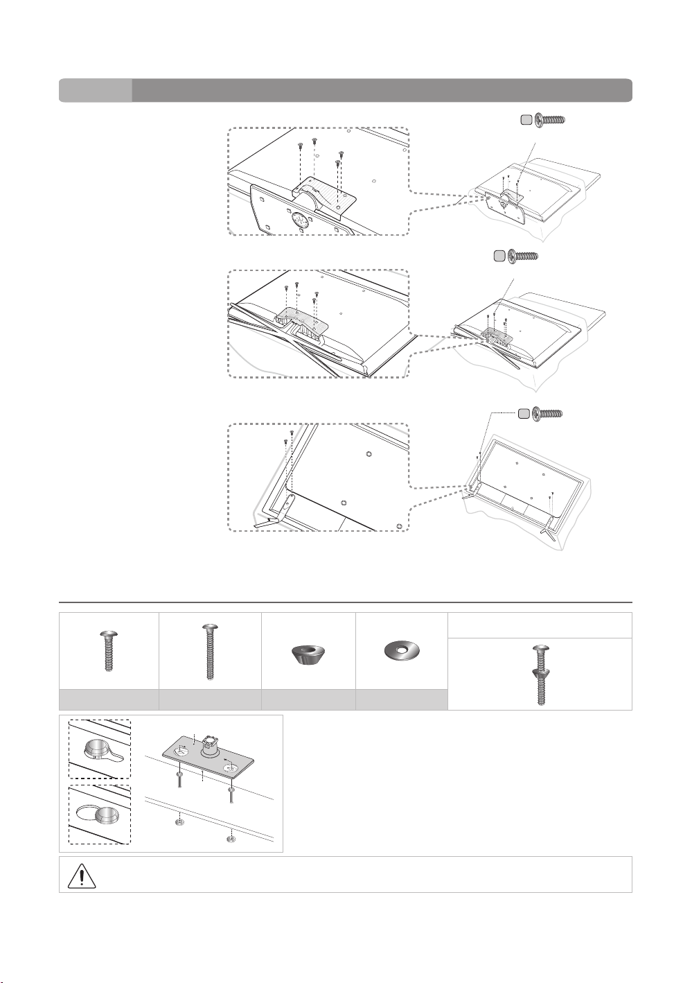
¦ Hotel Mount Kit
Short Bolt (2EA) Long Bolt (2EA) Nut (2EA) Washer (2EA)
Top
Affix the stand to a flat surface such as a dresser top, desk top, or
entertainment center as shown.
6
Bottom
WARNING: To prevent injury, this apparatus must be securely attached to the floor/ table in accordance with the
installation instructions.
English
Bolt + Nut
Page 7

HG890 Model
Stand Components
When installing the stand, use the provided components and parts.
A B D
1
3
1EA
2EA
2
4
C
×12(M4×L14)
C
X 8 (M4 X L14)
2EA
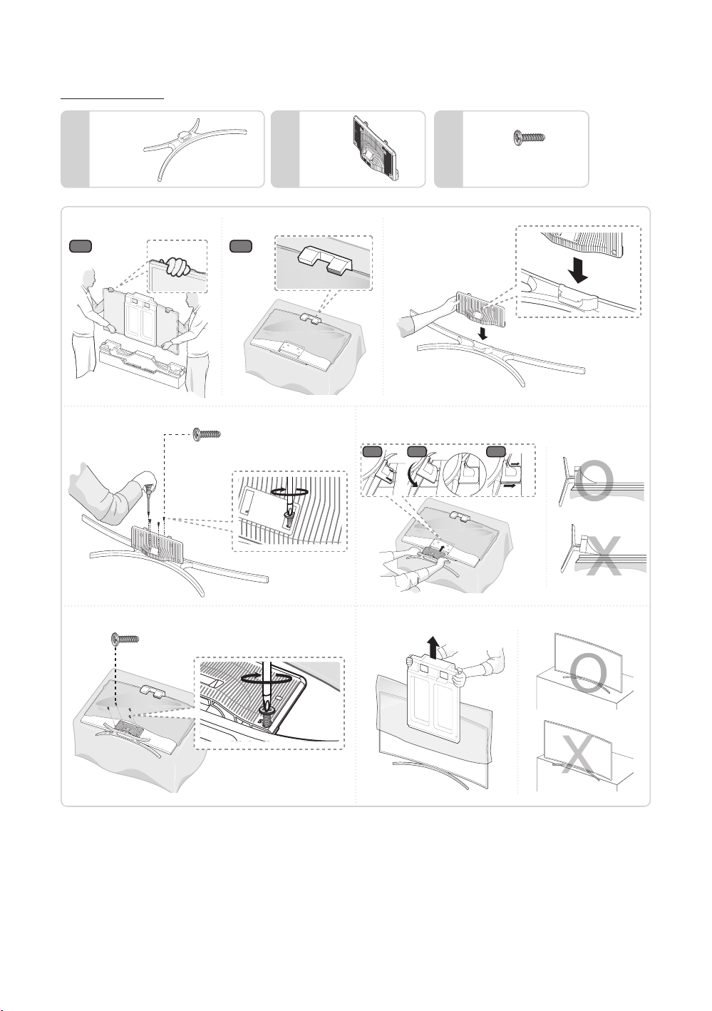
− Lay the TV on a soft surface, screen down.
− Use the packing marerial to protect the screen.
5
C
− Make sure to distinguish between the front and back of the Stand and the Stand Guide when assembling them.
− Make sure that at least two people lift and move the TV.
X 4
(M4 X L14)
6
English
7
Page 8
HG890V Model
1EA
A B C
1
1-1
3
1-2
x4 (M4 X L12)
1EA
4
4-1
2
4-2
X8(M4 X L12)
4-3
8
5
6
x4 (M4 X L12)
English
Page 9

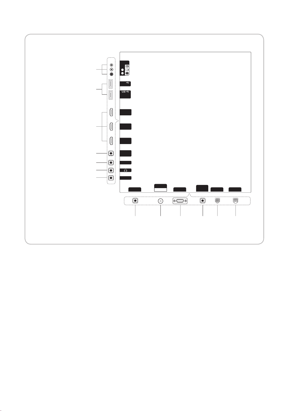
Viewing the Connection Panel
<CHINA Model>
HG40AC690**
HG48AC690**
HG60AC690**
HG65AC690**
HG75AC690**
<CHINA Model>
HG65AC890**
㾛书
1
2
3
4
Ꮋ
䷈书
ৈ
䕨ܺ
AV
USB
(5V 0.5A)
(HDD/1.0A)
/CLONING
HDMI
䕨ܺ 2
(DVI)
HDMI
䕨ܺ 1
ANT
᮵㒔᳞㒔
䕨ܺ
3 5 6 7
HDMI 䕨ܺ 3
(ARC)
HP-ID
⬊ᄥ⤀ⴑ
RJP
PC
䕨ܺ
PC/DVI
䷈书䕨ܺ
㾛书䕨ߏ
ৄভ䷈书䕨ߏ
ᘧ䞤䷈书䕨ߏ
䷈ࠋ
8
9
0
!@#$%
5 6 7 8
㾛书
㾛书
Ꮋ
1
1
2
2
3
3
Ꮋ
䷈书
䷈书
ৈ
ৈ
AV
䕨ܺ
AV
䕨ܺ
USB
USB
(5V 0.5A)
(5V 0.5A)
(HDD/1.0A)
(HDD/1.0A)
/CLONING
/CLONING
HDMI
HDMI
䕨ܺ 2
䕨ܺ 2
(DVI)
(DVI)
HDMI
HDMI
䕨ܺ 1
䕨ܺ 1
3 5 6 7
HDMI 䕨ܺ 3
HDMI 䕨ܺ 3
(ARC)
(ARC)
HP-ID
HP-ID
⬊ᄥ⤀ⴑ
⬊ᄥ⤀ⴑ
RJP
RJP
䕨ܺ
䕨ܺ
PC
PC
PC/DVI
PC/DVI
䷈书䕨ܺ
䷈书䕨ܺ
ৄভ䷈书䕨ߏ
ৄভ䷈书䕨ߏ
ᘧ䞤䷈书䕨ߏ
ᘧ䞤䷈书䕨ߏ
䷈ࠋ
䷈ࠋ
9
8
0
9
!
0
ANT
䕨ܺ
ANT
4
4
᮵㒔᳞㒔
᮵㒔᳞㒔
䕨ܺ
@#$%
@#$%
English
9
Page 10
HG55/65AC890V**
1
2
AV
䕨ܺ
㾛书
Ꮋ
ৈ
USB
(5V 0.5A)
(HDD/1.0A)
/CLONING
HDMI 䕨ܺ
3 (DVI)
3
9
%
5
#
HDMI 䕨ܺ
2
HDMI 䕨ܺ
1 (ARC)
ৄভ䷈书䕨ߏ
ᘧ䞤䷈书䕨ߏ
⬊ᄥ⤀ⴑ
HP-ID
ANT
䕨ܺ
PC
RJP
᮵㒔᳞㒔
䕨ܺ
PC/DVI
䷈书䕨ܺ
DATA
LAN
4 7 @ 8 6$
10
English
Page 11
2
PC
䕨ܺ
HP-ID
⬊ᄥ⤀ⴑ
RJP
HDMI 䕨ܺ 3
(ARC)
䷈ࠋ
PC/DVI
䷈书䕨ܺ
HDMI
䕨ܺ 2
(DVI)
USB
(5V 0.5A)
(HDD/1.0A)
/CLONING
᮵㒔᳞㒔
ANT
䕨ܺ
AV
䕨ܺ
ৈ
䷈书
Ꮋ
㾛书
HDMI
䕨ܺ 1
!
0
9
1
3
4
5 6 7 8
@#$%
ৄভ䷈书䕨ߏ
ᘧ䞤䷈书䕨ߏ
2
PC
䕨ܺ
HP-ID
⬊ᄥ⤀ⴑ
RJP
HDMI 䕨ܺ 3
(ARC)
䷈ࠋ
PC/DVI
䷈书䕨ܺ
HDMI
䕨ܺ 2
(DVI)
USB
(5V 0.5A)
(HDD/1.0A)
/CLONING
᮵㒔᳞㒔
ANT
䕨ܺ
AV
䕨ܺ
ৈ
䷈书
Ꮋ
㾛书
HDMI
䕨ܺ 1
0
9
8
1
3
4
3 5 6 7
@#$%
ৄভ䷈书䕨ߏ
ᘧ䞤䷈书䕨ߏ
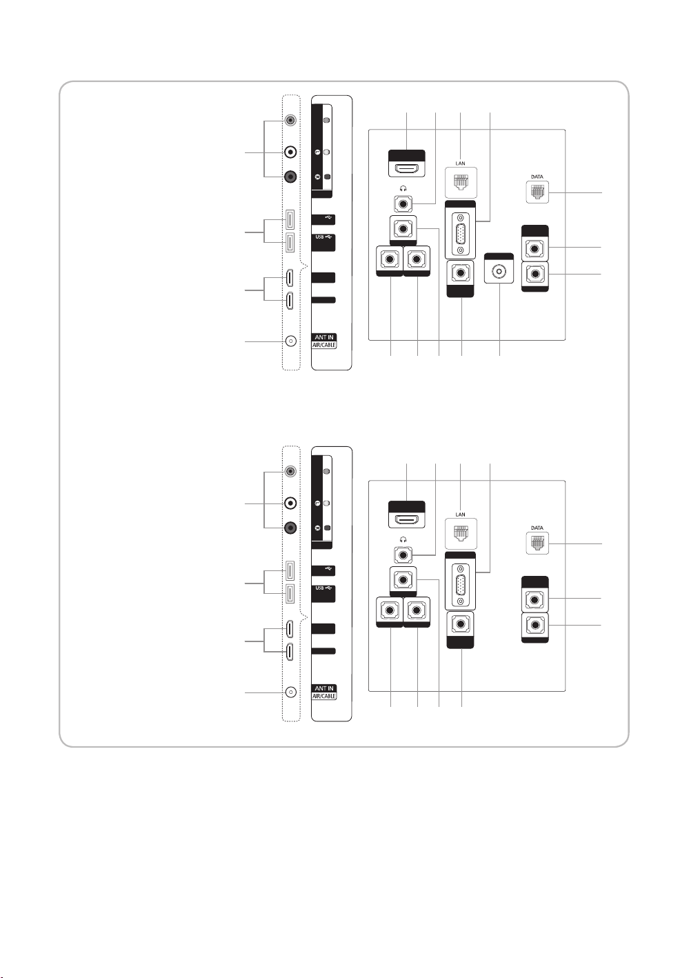
<HONG KONG
Model>
HG40AC690**
HG48AC690**
HG60AC690**
HG65AC690**
VIDEO
AUDIO
AV IN
USB
(5V 0.5A)
(HDD/1.0A)
/ CLONING
HDMI IN 2
(DVI)
HDMI IN 1
1
2
3
3 5 6 7
HDMI IN 3
(ARC)
HP-ID
DOOR-EYE RJP
PC IN
PC/DVI
AUDIO IN
VIDEO OUT
VARIABLE
AUDIO OUT
VOL-CTRL
8
9
0
4
!@#$%
<HONG KONG Model>
HG65AC890**
VIDEO
1
2
3
AUDIO
AV IN
USB
(5V 0.5A)
(HDD/1.0A)
/ CLONING
HDMI IN 2
(DVI)
HDMI IN 1
3 5 6 7
HDMI IN 3
(ARC)
HP-ID
DOOR-EYE RJP
PC IN
PC/DVI
AUDIO IN
VARIABLE
AUDIO OUT
VOL-CTRL
8
9
0
4
@#$%
English
11
Page 12

− Whenever you connect an external device to your TV, make sure that power on the unit is turned off.
− When connecting an external device, match the colour of the connection terminal to the cable.
1
VIDEO/L-AUDIO-R
− Connect a VIDEO cable to an appropriate external A/V device such a VCR, DVD or Camcorder.
− Connect audio cables to L-AUDIO-R on your TV and other ends to corresponding audio out jacks on the A/V device.
2
USB (HDD/1.0A) / CLONING , USB (5V 0.5A)
− Connector for software upgrades and My Downloads, etc.
− Service connection.
3
HDMI IN 1, 2(DVI), 3(ARC) / HDMI IN 1(ARC), 2, 3(DVI) for HC890V model: Connects to the HDMI jack of a device with
an HDMI output.
− No sound connection is needed for an HDMI to HDMI connection.
− Use the HDMI IN 2(DVI) jack for DVI connection to an external device. Use a DVI to HDMI cable or DVI-HDMI adapter
(DVI to HDMI) for video connection and the PC/DVI AUDIO IN jacks for audio.
4
ANT IN(AIR/CABLE): To view television channels correctly, a signal must be received by the set from one of the following
sources: An outdoor antenna; A cable television network;
5
HEADPHONE JACK
− Headphones may be connected to the headphone jack on your TV. While the headphones are connected, the
soundfrom the built-in speakers will be disabled.
6
LAN: Connect to a wired LAN using CAT 5 cable.
7
PC IN: Connect to the video output jack on your PC.
8
DATA
− Used to support data communication between the TV and the SBB.
− The TV jack type is RJ-12.
9
VARIABLE AUDIO OUT: Used for the audio output to the Bathroom speaker. Connect the Bathroom Wall Box and the
Variable port.
0
VOL-CTRL: Used to control the volume of the Bathroom speaker. Connect the Bathroom Wall Box and the VOL-CTRL
port. (HC890V model do not support)
!
VIDEO OUT (HC890V model do not support)
@
PC/DVI AUDIO IN: Connect to the audio output jack on your PC.
#
HP-ID : Connect the cable to HP-ID and Headphone Jack simultaneously and connect it to separated Headphone Box.
When connecting Headphone to Headphone Box, it works same as Headphone function.
$
RJP: This port is an RJP (Remote Jack Pack) communication port that enables connecting different devices to additional
modules so as to improve device use and convenience.
%
DOOR EYE:
12
English
Page 13

¦ Display Modes
Both screen position and size vary depending on the type of monitor and its resolution.
The resolutions in the table are recommended.
− Optimal resolution is 1920 X 1080 @ 60 Hz.
Mode Resolution
IBM
MAC
VESA CVT
VESA DMT
VESA GTF
VESA DMT / DTV CEA 1920 x 1080p 67.500 60.000 148.500 +/+
640 x 350
720 x 400
640 x 480
832 x 624
1152 x 870
720 x 576
1152 x 864
1280 x 720
1280 x 960
640 x 480
640 x 480
640 x 480
800 x 600
800 x 600
800 x 600
1024 x 768
1024 x 768
1024 x 768
1152 x 864
1280 x 1024
1280 x 1024
1280 x 720
1280 x 800
1280 x 800
1280 x 960
1366 x 768
1440 x 900
1440 x 900
1680 x 1050
1280 x 720
1280 x 1024
Horizontal Frequency
(KHz)
31.469
31.469
35.000
49.726
68.681
35.910
53.783
56.456
75.231
31.469
37.861
37.500
37.879
48.077
46.875
48.363
56.476
60.023
67.500
63.981
79.976
45.000
49.702
62.795
60.000
47.712
55.935
70.635
65.290
52.500
74.620
Vertical Frequency
(Hz)
70.086
70.087
66.667
74.551
75.062
59.950
59.959
74.777
74.857
59.940
72.809
75.000
60.317
72.188
75.000
60.004
70.069
75.029
75.000
60.020
75.025
60.000
59.810
74.934
60.000
60.015
59.887
74.984
59.954
70.000
70.000
Pixel Clock Frequency
(MHz)
25.175
28.322
30.240
57.284
100.000
32.750
81.750
95.750
130.000
25.175
31.500
31.500
40.000
50.000
49.500
65.000
75.000
78.750
108.000
108.000
135.000
74.250
83.500
106.500
108.000
85.500
106.500
136.750
146.250
89.040
128.943
Sync Polarity
(H / V)
+/-
-/+
-/-
-/-
-/-
-/+
-/+
-/+
-/+
-/-
-/-
-/+/+
+/+
+/+
-/-
-/+/+
+/+
+/+
+/+
+/+
-/+
-/+
+/+
+/+
-/+
-/+
-/+
-/+
-/-
− When using an HDMI/DVI cable connection, you must use the HDMI IN 2 (DVI) jack.
− The interlace mode is not supported.
− The set might operate abnormally if a non-standard video format is selected.
− Separate and Composite modes are supported. SOG is not supported.
Door Eye
− For CN/HK model only
− Door eye function works even piture menulock setted as ON in hotel option.
− In some conditions such as Auto storing, Picture Off, Power on Logo, etc., Door eye function does not work.
English
13
Page 14
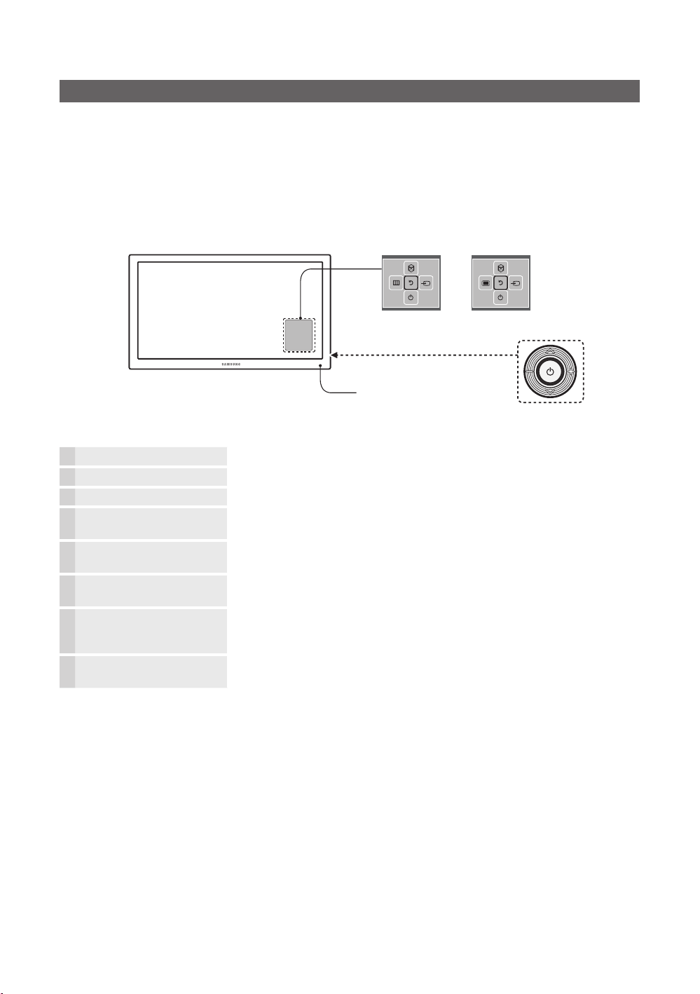
TV Controller
TV Controller is a multi directional button that helps navigate without using the remote control.
− Some functions which require a PIN code may not be available.
− The product colour, shape and menu OSD may vary, depending on the model.
− Exits the menu when pressing the controller for more than 1 second.
− When selecting the function by moving the controller to the up/down/left/right directions, do not to press the controller. If
the controller is used first, you cannot operate it to move the up/down/left/right directions.
Function menu
The image is drawn by facing
Remote control sensor
Power on Turns the TV on by pressing the controller in standby mode.
Adjusting the volume Adjusts the volume by moving the controller from side to side when the power is on.
Selecting a channel Selects a channel by moving the controller up and down when the power is on.
Using the function menu Press the controller when the power is on and the function menu appears. If you press
Using the Menu
Selecting the Source
Selecting the SMART HUB
(™)
Power Off
− To close the Menu, SMART HUB, or Source, press the Controller for more than 1 second.
it again, the function menu screen disappears.
Selects the MENU(m / J) by moving the controller in the function menu screen. The
OSD(On Screen Display) of your TV’s feature appears.
Selects the Source(s) by moving the controller in the function menu screen. The
Source list screen appears.
With the Function menu visible, select SMART HUB (™) by moving the Controller
upwards. The SMART HUB main screen appears. Select an application by moving
the Controller, and then pressing the Controller.
Selects the Power Off(P) to turn the TV off by moving the controller in the function
menu screen.
Only for China model
TV Controller
the front side of the TV.
<HG**AC690*** Model>
y Standby mode
Do not leave your TV in standby mode for long periods of time such as when on holiday. A small amount of electric power is
still consumed even when the power button is turned off. It is best to unplug the power cord.
English
14
Page 15

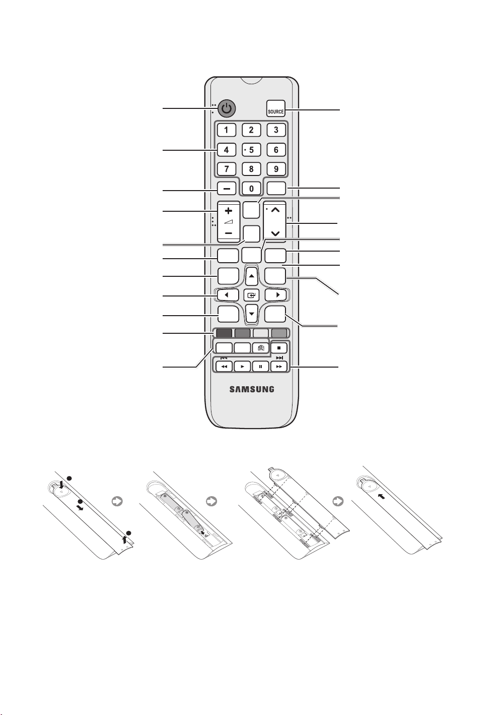
Viewing the Remote Control
− This is a special remote control for the visually impaired and has Braille points on the Power, Channel and Volume
buttons.
Hong Kong model
Turns the TV on and off.
Have direct access to channels
Alternately selects Teletext, Double
or Mix.
Adjust the volume.
Display channel list on the screen.
Display the main on-screen menu.
Quickly select frequently used
functions.
Select on-screen menu items and
change menu values.
Return to the previous menu.
Buttons in the Channel list,
Contents Home menu, etc.
ALARM: Enter the hour you want
the TV to turn on.
DUAL f-g: Sound effect selection.
: Turns the 3D image on or off.
(Some model does not support)
TTX/MIX
CH LIST
HOME
A B C D
DUAL f-g
ALARM
GUIDE
CONTENT
CLOCK
Display and select available video
sources.
Electronic Programme Guide (EPG)
display.
Cut off the sound temporarily.
Change channels.
Swich to the HOME Screen.
View the My Downloads.
When you press INFO key for 7
seconds in standby mode, TV screen
displays the time.
Press to display information on the
TV screen.
Exit the menu.
Use these buttons in the Contents
Home.
English
15
Page 16
CHINA model
Turns the TV on and off.
Gives direct access to channels.
Alternately selects Teletext,
Double or Mix.
Adjusts the volume.
Displays channel lists on the
screen.
Display the main on-screen menu.
Quickly selects frequently used functions.
Select on-screen menu items and
change menu values.
Returns to the previous menu.
Buttons in the Channel list,
Contents Home menu, etc.
ALARM: Enter the hour you want
the TV to turn on.
DUALf-f: Sound effect
selection.
X: Turns the 3D image on or off.
( Some model does not support )
静音
MUTE
频道
列表
CH LIST
主页
项目
MENU HOME
工具
TOOLS
返回 退出
RETURN
A B C D
立体声切换闹钟
DUAL
ALARM
节目源
回看
PRE-CH
频道
CH
CONTENT
CLOCK
显示
INFO
EXIT
Displays and selects the available
video sources.
Electronic Programme Guide
(EPG) display.
Cuts off the sound temporarily.
Changes channels.
Swich to the HOME Screen.
View the My Downloads.
When you press INFO key for 7
seconds in standby mode, TV
screen displays the time.
Press to display information on
the TV screen.
Exits the menu.
Use these buttons in the
Contents Home.
y Installing batteries (Battery size: AAA)
X
Y
Z
After you have installed the batteries, use a screwdriver to screw in the screw that holds the battery cover closed.
(The Remocon may vary depending on the model.)
✎ NOTE
y Use the remote control within 23 feet of the TV.
y Bright light may affect the performance of the remote control. Avoid using nearby special fluorescent light or neon signs.
y The colour and shape may vary depending on the model.
English
16
Page 17

Using the Smart Touch Control
¢
Only for HG890 and HG890V Model (Hong Kong model)
¢
: Turns the sound off and on.
Press and Hold this button to access
Accessibility shortcuts
HOME
Microphone: Use the microphone with the Voice Control and Voice
functions.
The Voice Control function can be affected by unclear pronunciation,
voice level, or surrounding noise.
Turns the TV on/off.
SEARCH
: Press this button to use the search window. This is
available with various services. Use recent-viewing history to check
previously watched/accessed channels and contents.
(Depending on models)
KEYPAD
: With the virtual remote control on the screen, you can
easily enter digits, control content, and use functions.
SOURCE
: Changes the source.
VOICE
: Starts voice recognition. When the microphone icon
appears on the screen, say a voice command into the microphone.
Say "Help" to learn about basic usage and voice commands.
Say a voice command 10 cm to 15 cm from the microphone and at
an appropriate volume.
Changes the channel.
Changes the volume.
Touchpad
Smart Control. The pointer on the screen moves in the direction
and as much as the Samsung Smart Control is moved. Tap on the
touchpad to run the focused item.
< > ¡ £
RETURN
EXIT
applications.
SMART HUB
an application is running terminates the application.
GUIDE
CH.LIST
Controls for when viewing/playing a video, photo or music file or
watching a recorded programme. You can also use the buttons to
control contents from an external device.
: Place a finger on the touch pad and move the Samsung
: Moves the pointer or focus.
: Returns to the previous menu.
: Press and hold this button to exit all currently running
: Launches Smart Hub. Pressing
: Displays the digital channel broadcasting schedule.
: Press and hold to launch the
CH.LIST
SMART HUB
.
while
Colour button
options specific to the feature in use.
MENU
: Displays the menu on the screen.
HOME
: Only used in Widget TV.
: Use these colour buttons to access additional
English
17
Page 18

CHINA model
M: Turns the sound off and on.
Press and Hold this button to access
Accessibility shortcuts
更多 信号源
频道
CH
返回
退出
项目 主页
指南
HOME
Microphone: Use the microphone with the Voice Control and Voice
functions.
The Voice Control function can be affected by unclear pronunciation,
voice level, or surrounding noise.
Turns the TV on/off.
SEARCH: Press this button to use the search window. This is
available with various services. Use recent-viewing history to check
previously watched/accessed channels and contents.
(Depending on models)
KEYPAD: With the virtual remote control on the screen, you can
easily enter digits, control content, and use functions.
SOURCE: Changes the source.
VOICE: Starts voice recognition. When the microphone icon
appears on the screen, say a voice command into the microphone.
Say "Help" to learn about basic usage and voice commands.
Say a voice command 10 cm to 15 cm from the microphone and at
an appropriate volume.
Changes the channel.
Changes the volume.
Touchpad: Place a finger on the touch pad and move the Samsung
Smart Control. The pointer on the screen moves in the direction
and as much as the Samsung Smart Control is moved. Tap on the
touchpad to run the focused item.
< > ¡ £: Moves the pointer or focus.
RETURN: Returns to the previous menu.
EXIT: Press and hold this button to exit all currently running
applications.
SMART HUB: Launches Smart Hub. Pressing SMART HUB while
an application is running terminates the application.
GUIDE: Displays the digital channel broadcasting schedule.
CH.LIST: Press and hold to launch the CH.LIST.
Controls for when viewing/playing a video, photo or music file or
watching a recorded programme. You can also use the buttons to
control contents from an external device.
18
Colour button: Use these colour buttons to access additional
options specific to the feature in use.
MENU: Displays the menu on the screen.
HOME: Only used in Widget TV.
English
Page 19

Pairing the Samsung Smart Control
To control the TV with Samsung Smart Control, you need to pair Samsung Smart Control to the TV via Bluetooth. Pair
Samsung Smart Control to the TV.
− Samsung Smart Control can only be paired to a single TV.
1 Point Samsung Smart Control at the remote control sensor of the TV and press the TV button to turn the TV on.
− Remote control receiver’s location may vary depending on the model.
2. The Bluetooth icon will appear on the screen as shown below. The TV will then attempt to connect to the Samsung Smart
Control unit automatically.
<Connection attempt and completion icons>
Reconnecting Samsung Smart Control
If the Samsung Smart Control stops operating or works abnormally, replace the batteries as this may be due to insufficient
battery power.
If the problem persists, the Samsung Smart Control restore pairing with the TV.
1. Press RETURN button and GUIDE button simultaneously for 3 seconds.
− You have to control Samsung Smart Control apart from TV within 30cm ~ 40cm. But, you must place Samsung
Smart Control toward to TV's remote control receiver.
2. Connection image is appeared on the screen. And then, Samsung Smart Control is connecting to TV automatically.
English
19
Page 20

Low Battery Power Warning
When the Smart Touch Control’s battery power is low, the indicator shown (in the illustration) below
appears on the bottom left of the TV screen. Replace the old batteries with new alkaline ones.
✎ NOTE
y Use the remote control within 7 feet of the TV.
y Bright light may affect the performance of the remote control. Avoid using nearby special fluorescent light or neon signs.
y The colour and shape may vary depending on the model.
Installing batteries (Battery size: AA)
1. Gently pull on the battery cover's notch and then remove the cover completely once it comes loose.
2. Insert 2 AA alkaline batteries, making sure to align the positive and negative polarities correctly.
3. Place the battery cover on the remote control and insert the top part of the cover into the remote control.
4. Press the catches on both sides of the battery cover in the order shown so that the cover is completely attached to the
remote control.
Using the TV by Moving the Samsung Smart Control
The Samsung Smart Control has a motion sensor (gyro sensor) that allows you to easily control the TV by holding and moving
the Samsung Smart Control.
After Placing a finger on the touchpad, a pointer appears on the screen. Hold and move the Samsung Smart Control. The
pointer moves the same way the Samsung Smart Control is moved. It's also possible to scroll up and down on scrollable
screens.
− If you remove the finger from touchpad, the screen pointer disappears.
English
20
Page 21

Using the TV with the Touchpad
− Navigate to the System > Smart Control Settings menu and select the Touch Sensitivity option to change the touchpad
sensitivity. If the touchpad sensitivity is too slow or fast, change the sensitivity using the Touch Sensitivity option.
Moving the Focus/Ponter
Press the directional buttons (up, down, left, and right) to move the pointer or focus in the direction.
Menu Access & Item Selection
Tap on the touchpad. This lets you access a TV menu or select an item.
Displaying the Channel List
Press and hold the touchpad while watching TV to bring up the Channel List on the screen.
Displaying the Context-sensitive Menu on Smart Hub
Tap and hold on the touch pad from the Smart Hub screen. The Options menu available to the selected item appears.
− The Options menu depends on the context.
Moving to the Smart Hub panel
On the Smart Hub screen, drag left or right on the touchpad. This transits the screen by panel.
Scrolling on the Web Browser
Drag up/down on the touchpad in the web browser screen. This scrolls through the web screen.
Displaying the Remote Control on the Screen (virtual remote control)
Press the KEYPAD button to display the virtual remote control on the screen. You can easily enter digits, control content, and
use TV buttons with the virtual remote control.
− The virtual remote control buttons may vary depending on the TV's current status.
English
21
Page 22

Connecting to the Network
You can set up your TV so that it can access the SMART TV applications through your local area network (LAN) using a wired
or wireless connection.
− After you have “physically” connected your TV to your network, you must configure the network connection to complete
the process. You can configure the connection after the Initial Setup process, through the Hotel Option.
Network Connection - Wireless
You can connect your TV to your local area network (LAN) through a standard wireless router or modem.
Wireless IP Router or Modem
(router having DHCP Server)
The LAN Port on the Wall
LAN Cable (Not Supplied)
This TV supports the IEEE 802.11a/b/g and n communication protocols. Samsung recommends using IEEE 802.11n. When
you play video over a network connection, the video may not play smoothly.
Most wireless network systems incorporate a security system that requires devices that access the network through an access
point or AP (typically a wireless IP Sharer - router or modem) to transmit an encrypted security code called an access key.
Your TV is compatible with the following security protocols:
y Authentication Mode: OPEN, SHARED, WPAPSK, WPA2PSK
y Encryption Type: WEP, TKIP, AES
In compliance with the newest Wi-Fi certification specifications, Samsung TVs do not support WEP or TKIP security encryption
in networks running in the 802.11n mode.
22
English
Page 23

Network Connection - Wired
PC IN
HDMI IN 3
(ARC)
PC IN
HDMI IN 3
(ARC)
PC IN
HDMI IN 3
(ARC)
PC IN
HDMI IN 3
(ARC)
PC IN
HDMI IN 3
(ARC)
PC IN
HDMI IN 3
(ARC)
PC IN
HDMI IN 3
(ARC)
PC IN
HDMI IN 3
(ARC)
PC IN
HDMI IN 3
(ARC)
PC IN
HDMI IN 3
(ARC)
PC IN
HDMI IN 3
(ARC)
PC IN
HDMI IN 3
(ARC)
There are three main ways to connect your TV to your network using cable, depending on your network setup. They are
illustrated below:
y HC690 Model
The Modem Port on the Wall
The Modem Port on the Wall
Modem Cable
(Not Supplied)
The LAN Port on the Wall
External Modem
(ADSL / VDSL / Cable TV)
External Modem
(ADSL / VDSL / Cable TV)
LAN Cable
(Not Supplied)
LAN Cable (Not Supplied)Modem Cable (Not Supplied)
IP Router that has a
DHCP Server
TV Rear Panel
TV Rear Panel
LAN Cable
(Not Supplied)
TV Rear Panel
LAN Cable (Not Supplied)
English
23
Page 24

y HC890 Model
PC IN
HDMI IN 3
(ARC)
PC IN
HDMI IN 3
(ARC)
PC IN
HDMI IN 3
(ARC)
PC IN
HDMI IN 3
(ARC)
PC IN
HDMI IN 3
(ARC)
PC IN
HDMI IN 3
(ARC)
PC IN
HDMI IN 3
(ARC)
PC IN
HDMI IN 3
(ARC)
PC IN
HDMI IN 3
(ARC)
PC IN
HDMI IN 3
(ARC)
PC IN
HDMI IN 3
(ARC)
PC IN
HDMI IN 3
(ARC)
The Modem Port on the Wall
The Modem Port on the Wall
Modem Cable
(Not Supplied)
The LAN Port on the Wall
External Modem
(ADSL / VDSL / Cable TV)
External Modem
(ADSL / VDSL / Cable TV)
LAN Cable
(Not Supplied)
LAN Cable (Not Supplied)Modem Cable (Not Supplied)
IP Router that has a
DHCP Server
TV Rear Panel
TV Rear Panel
LAN Cable
(Not Supplied)
TV Rear Panel
24
LAN Cable (Not Supplied)
English
Page 25

y HC890V Model
DATA
C/DVI
书䕨ܺ
DATA
C/DVI
LAN
DATA
C/DVI
书䕨ܺ
DATA
C/DVI
书
䕨ܺ
LAN
DATA
C/DVI
书䕨ܺ
DATA
C/DVI
书
䕨ܺ
LAN
DATA
C/DVI
书䕨ܺ
DATA
C/DVI
书
䕨ܺ
LAN
DATA
C/DVI
书䕨ܺ
DATA
C/DVI
书
䕨ܺ
LAN
DATA
C/DVI
书䕨ܺ
DATA
C/DVI
书
LAN
The Modem Port on the Wall
The Modem Port on the Wall
Modem Cable
(Not Supplied)
The LAN Port on the Wall
External Modem
(ADSL / VDSL / Cable TV)
External Modem
(ADSL / VDSL / Cable TV)
LAN Cable
(Not Supplied)
LAN Cable (Not Supplied)Modem Cable (Not Supplied)
IP Router that has a
DHCP Server
TV Rear Panel
书䕨ܺ
TV Rear Panel
䕨ܺ
LAN Cable
(Not Supplied)
TV Rear Panel
LAN Cable (Not Supplied)
− The TV does not support network speeds of 10Mbps or less.
− Use Cat 6 or CAT 7 (STP Type*) cable for the connection. (*Shielded Twisted Pair)
English
25
Page 26

Connecting the TV with SBB
PC
D
DOO
E
RJP
OUT
HD
3
(
)
PC/
AUDIO IN
OUT
L
PC IN
(ARC)
PC IN
(ARC)
LAN
LAN
䕨ܺ
DATA
(Inlay sample may vary depending on the model.)
y HG690 model
TV Rear Panel
HDMI IN 3
MI IN
ARC
(ARC)
ETH MODEM
y HG890 model
TV Rear Panel
Data Cable
HP-ID
HP-I
DOOR-EYE RJP
R-EY
Data Cable
PC IN
IN
PC/DVI
DVI
AUDIO IN
VIDEO OUT
VIDEO
VARIABLE
VARIABLE
AUDIO
AUDIO OUT
VOL-CTRL
VOL-CTR
ETH MODEM
y HG890V model
TV Rear Panel
Data Cable
1. Connect the DATA jack of the TV to the [ETH MODEM] jack of the STB (SBB) with the Data cable.
(Some area does not supply data cable)
− Use data communication.
26
English
ETH MODEM
Page 27

¦ List of Vendors and Compatible Data Cables Supplied with the TV (Some
area does not supply data cable with TV)
Confirm you are using the correct data cable for your vendor. Refer to the code label on the data cables.
English
27
Page 28

Connecting the Bathroom Speakers
N
OUT
AUDIO IN
N
AUDIO IN
You can connect the Bathroom Speakers using the following method.
¦ Connecting through the Variable Output (available without an external
amplifier)
(Inlay sample may vary depending on the model.)
y HG690 model
TV Rear Panel
PC IN
PC I
PC/DVI
PC/DVI
AUDIO IN
y HG890 model
TV Rear Panel
PC IN
PC I
VIDEO OUT
VIDEO
VARIABLE
AUDIO OUT
VOL-CTRL
VARIABLE
AUDIO OUT
1
2
1
VOL+
VOL
-
Speaker
Volume Control Box
Speaker
28
English
PC/DVI
PC/DVI
AUDIO IN
VOL-CTRL
2
VOL+
VOL
Volume Control Box
-
Page 29

y HG890V model
䕨ܺ
)
TV Rear Panel
1
Speaker
1. Connect the VARIABLE AUDIO OUT port of the TV to the Bathroom Wall Speakers of the hotel.
Speaker -
HDMI 䕨ܺ
HDMI
1 (ARC
1 (ARC)
ৄভ䷈书䕨ߏ
ᘧ䞤䷈书䕨ߏ
⬊ᄥ⤀ⴑ
ᄥ⤀ⴑ
Speaker +
N/C
2. Connect the VOL-CTRL jack of the TV to the Volume Control Box Switch port on the Bathroom Wall of the hotel.
− The maximum speaker output is 4W, 8Ω.
− The VARIABLE AUDIO OUT port supports MONO sound out only.
y Installing the Volume Control
− If you configure the Volume Control Box as shown in the figure, you can control the volume of the bathroom speakers.
− The jack that connects the Volume Control Box to the TV is a 3.5mm normal Phone jack.
− Volume Control Box switch is a Tact switch.
✎ Setting the Sub AMP Mode
− 0: Turns the Sub AMP function off (PWM off).
− 1: Determines the Sub volume according to the main volume control. the sub volume is determined according to the
Power On Volume, the Min Volume, and the Max Volume values of Hotel Mode.
− 2: Determines the volume according to the bathroom control panel setting.
y Variable Output Port Specifications
− Speaker Wire: Use speaker cable no more than 82 feet (25m) in length.
Volume Control Box
VOL
-
VOL +
VOL - DOWN
( White
1
)
VOL - UP
( Black /Red
GND
2
)
( Shield Wire 3 )
1
3
2
English
29
Page 30

¦ Audio Loop In
JP
OUT
3
)
N
JP
3
)
N
An addition Headphone Box can be installed on a bed or business desk for added convenience. The installation procedures
are given below.
y Detailed Drawing of the Headphone Box.
(Inlay sample may vary depending on the model.)
y HG690 model
TV Rear Panel
HDMI IN 3
HDMI IN
ARC
(ARC)
y HG890 model
TV Rear Panel
HP-ID
DOOR-EYE RJP
DOOR-EYER
HDMI IN 3
HDMI IN
ARC
(ARC)
HP-ID
DOOR-EYE RJP
DOOR-EYER
PC IN
PC/DVI
PC/DVI
AUDIO I
AUDIO IN
PC IN
IN
PC/DVI
PC/DVI
AUDIO I
AUDIO IN
IN
VARIABLE
VARIABLE
DIO OUT
AUDIO OUT
VIDEO OUT
VIDEO
VOL-CTRL
L-CTRL
HEADPHON BOX
Headphone Box
HEADPHON BOX
VARIABLE
VARIABLE
DIO OUT
AUDIO OUT
VOL-CTRL
L-CTRL
Headphone Box
English
30
Page 31

y HG890V model
ᘧ䞤䷈书䕨ߏ
HEADPHON BOX
Headphone Box
TV Rear Panel
⬊ᄥ⤀ⴑ
ᄥ⤀ⴑ
HP-ID
TV HP-ID jack
Shield wire
Red Wire (Audio-R)
Red wire + White wire
TV Headphones jack
Whitewire (Audio-L)
Shield Wire
<Headphone Box>
English
31
Page 32

Connecting the MediaHub HD
SB
)
O
O
D
T
E
SB
)
)
N
O
O
N
D
N
E
Output to any external source connected to MediaHub HD on the hotel desk.
(Inlay sample may vary depending on the model.)
y HG690 model
TV Rear Panel MediaHub HD Rear
VIDEO
VIDE
HDMI
USB RS/232
DOOR-EYE
DOOR-EYE
HDMI IN 3
(ARC)
HP-ID
HP-I
PC IN
IN
2
VARIABLE
ARIABL
UDIO OUT
AUDIO OUT
VIDEO OUT
PC/DVI
C/DVI
AUDIO IN
AUDIO IN
VIDEO OU
VOL-CTRL
L-CTRL
RJP
HDMI cable
1
RS-232 Data Cable
AUDIO
AUDI
AV IN
AV I
USB
U
(5V 0.5A)
5V 0.5A
(HDD/1.0A)
HDD/1.0A)
/ CLONING
/ CLONING
HDMI IN 2
(DVI)
HDMI IN 1
y HG890 model
TV Rear Panel MediaHub HD Rear
USB RS/232
VIDEO
VIDE
AUDIO
AUDI
AV IN
AV I
USB
U
(5V 0.5A)
5V 0.5A
(HDD/1.0A)
HDD/1.0A
/ CLONING
/ CLONING
HDMI IN 2
(DVI)
HDMI IN 1
DOOR-EYE
DOOR-EYE
HDMI IN 3
(ARC)
HP-ID
HP-I
PC IN
PC I
2
VARIABLE
ARIABL
UDIO OUT
AUDIO OUT
RJP
PC/DVI
C/DVI
AUDIO I
AUDIO IN
VOL-CTRL
L-CTRL
HDMI cable
HDMI
1
RS-232 Data Cable
English
32
Page 33

y HG890V model
ܺ
D
᳞㒔
MediaHub HD Rear
USBRS/232
HDMI
2
1
RS-232 Data Cable
HDMI cable
HDMI 䕨ܺ
3 (DVI)
HDMI 䕨ܺ
2
HDMI 䕨ܺ
1 (ARC)
ৄভ䷈书䕨ߏ
ভ䷈书䕨ߏ
ᘧ䞤䷈书䕨ߏ
ᘧ䞤䷈书䕨ߏ
⬊ᄥ⤀ⴑ
ᄥ⤀ⴑ
HP-ID
-I
RJP
TV Rear Panel
ANT
䕨ܺ
PC
᮵㒔᳞㒔
PC
䕨
1. Connect the RJP port of the TV and the RS/232 port of the MediaHub HD.
2. Connect the 1 or 2(DVI) or 3(ARC) (HDMI IN 1(ARC), 2, 3(DVI) for HC890V model) port of the TV and the HDMI port of the
MediaHub HD.
y MediaHub HD
− The MediaHub HD is a hardware module that has different Audio Video inputs (A/ V, Audio, PC, HDMI and USB)
and corresponding outputs. The corresponding output sources connect from MediaHub to the TV. MediaHub
communicates with the TV via RS232. Hot Plug & Play is a function that allows hotel guests to connect an external
source to the MediaHub. MediaHub communicates with the TV by sending messages regarding Active/Inactive
sources. The TV switches to the Active external source.
− You have to connect the HDMI of the MediaHub to the HDMI port of the T V.
− When the T V is on, connect the TV and the RJP within 10 seconds.
y Special features
− Plug & Play
− Auto Detection
English
33
Page 34

Connecting the RJP (Remote Jack Pack)
)
D
E
L
O
AUDIO
AUDIO/PC
RS/
3
Output to any external source connected to RJP on the hotel desk.
(Inlay sample may vary depending on the model.)
y HG690 model
4 HDMI cable
TV Rear Panel
USB HDMI VIDEO
USB HDMI VIDEO
RJP Rear
y HG890 model
4 HDMI cable
3 Video Cable
2 Audio Cable
AUDIO AUDIO/PC
AUDIO AUDIO/PC
5
1
3 Video Cable
RS/232
RS/232
D-sub / PC Audio cable
VIDEO
AUDIO
AV IN
USB
(5V 0.5A)
(HDD/1.0A)
/ CLONING
HDMI IN 2
(DVI)
HDMI IN 1
VIDEO
DOOR-EYE
HDMI IN 3
(ARC)
HP-ID
PC IN
VARIABLE
AUDIO OUT
VIDEO OUT
RJP
PC/DVI
AUDIO IN
VOL-CTRL
TV Rear Panel
DOOR-EYE
HDMI IN 3
(ARC)
PC IN
VARIABLE
ARIABLE
AUDIO OUT
HP-ID
HP-I
R-EY
RJP
PC/DVI
AUDIO IN
UDIO OUT
VOL-CTRL
OL-CTR
2 Audio Cable
AUDIO AUDIO/PC
USB HDMI VIDEO
B
USB HDMI VIDEO
AUDIO AUDIO/PC
DMI
IDE
RS/232
RS/232
2
2
RJP Rear
5
D-sub / PC Audio cable
1
English
34
AUDIO
AV IN
USB
5V 0.5A
(5V 0.5A)
(HDD/1.0A)
(HDD/1.0A)
/ CLONING
/ CLONING
HDMI IN 2
(DVI)
HDMI IN 1
Page 35

y HG890V model
A
SB
)
)
G
D
A
᳞㒔
O
AUDIO
AUDIO/PC
RS/
3
3 Video Cable
AUDIO AUDIO/PC
USB HDMI VIDEO
B
USB HDMI VIDEO
RJP Rear
AUDIO AUDIO/PC
DMI
IDE
2 Audio Cable
RS/232
RS/232
2
2
4 HDMI cable
5
AV
䕨ܺ
㾛书
Ꮋ
ৈ
USB
U
(5V 0.5A
(5V 0.5A)
(HDD/1.0A)
HDD/1.0A
/CLONING
CLONIN
HDMI 䕨ܺ
3 (DVI)
HDMI 䕨ܺ
2
HDMI 䕨ܺ
1 (ARC)
ৄভ䷈书䕨ߏ
ৄভ䷈书䕨ߏ
ᘧ䞤䷈书䕨ߏ
ᘧ䞤䷈书䕨ߏ
⬊ᄥ⤀ⴑ
⬊ᄥ⤀ⴑ
HP-ID
-I
RJP
ANT
䕨ܺ
䕨ܺ
᮵㒔᳞㒔
TV Rear Panel
PC/DVI
䷈书䕨ܺ
DAT
PC
䕨ܺ
AT
D-sub / PC Audio cable
1
English
35
Page 36

1. Connect the PC IN / PC/DVI AUDIO IN port of the TV to the PC/AUDIO port of the RJP.
2. Connect the AV IN [L-AUDIO-R] port of the TV to the AUDIO port of the RJP.
3. Connect the AV IN [VIDEO] port of the TV to the VIDEO port of the RJP.
4. Connect the HDMI IN(1, 2(DVI) or 3(ARC)), HG890V model: HDMI IN(1(ARC), 2, 3(DVI)) port of the TV and the HDMI port
of the RJP.
5. Connect the RJP port of the TV and the RS/232 port of the RJP.
✎ The RJP (Remote Jack Pack) compatible with this Samsung TV is TeleAdapt TA-7610, TA-7650 (HD) and TA-7660 (HD
Plus).
y RJP (Remote Jack Pack): RJP stands for Remote Jack Pack. The RJP is a hardware module that has different Audio
Video inputs (A/V, Audio, PC and HDMI) and corresponding outputs. The corresponding output sources are connected
from RJP to TV. The RJP communicates with the TV via RS232. Hot Plug & Play is a function that allows hotel guests to
connect an external source to the RJP. The RJP communicates with the TV by sending messages regarding Active/Inactive
sources. The TV will switch to the Active external source according to the priority set by the User.
✎ You can select HDMI IN(1, 2(DVI) or 3(ARC)), HG890V model: HDMI IN(1(ARC), 2, 3(DVI)) and AV IN for connecting
RJP.
✎ When the TV is on, connect the TV and the RJP within 10 seconds.
y The RJP can be returned to the factory default settings by pressing the A/V and HDMI buttons simultaneously for 10
seconds. All LEDs blink 5 times to acknowledge that this has been finished.
y The RJP will automatically turn off any LEDs after 5 minutes to avoid unnecessary light pollution in the hotel room. The
LEDs that were turned off will turn on again if the guest touches any of the buttons and the 5 minute timer will restart. If the
guest then touches another source button, the TV will change to the selected source and the corresponding LED will be lit.
y After an RJP Reset or a TV Power OFF/ON, it takes approx. 10 seconds to establish communications between the TV and
the RJP.
y The following table shows the approximate time in seconds to switch from the TV to the input source, based on the priority.
✎ Scenario 1: When no inputs are connected.
Source To Connect
AV 2 Sec
PC 0.7 Sec
HDMI 3.9 Sec
✎ Scenario 2: When two or more inputs are connected and an Input source is disconnected and then reconnected.
Source Disconnect To Connect Total
AV 4.5 Sec 2 Sec 6.5 Sec
PC 0.7 Sec 0.7 Sec 1.4 Sec
HDMI 3.9 Sec 3.9 Sec 7.8 Sec
✎ E.g. If the RJP has all its live sources AV, PC and HDMI connected, AV is viewed as the highest priority. If the RJP is
in HDMI mode, and a guest removes and reconnects the AV, the minimum time required to switch to the AV is 6.5
seconds.
y To connect audio (Ipod or Mp3), Music mode should be ON.
y A/V, PC and HDMI input sources are supported.
36
English
Page 37

Setting the Hotel Option Data
To Enter: Press the MUTE → 1 → 1 → 9 → ENTER E buttons in order. (From the Hospitality mode, the Standalone mode is
set.)
To Exit from this menu : power off and turn on again.
✎ Depending on Model and Region, some menus do not exist on the TV set.
✎ Hotel factory menu is for Hotel option data setting only. Normal user operation should be strictly prohibited.
No
1 Hospitality Mode Standalone Select the Hotel TV mode. (Standalone / Interactive)
2 SI Vendor OFF
Power
3
On
4 Channel
5 Menu OSD
Hotel TV Function
Category initial value
Power On Channel Last Saved
Power On Channel Num ... When the TV is turned on, it switches automatically to this channel.
Power On Channel Type ...
Power On Volume Last Saved
Power On Volume Num ... The TV turns on with this Volume Level in Stand Alone Hospitality mode.
Min Volume 0 Minimum Volume Level setting user can set
Max Volume 100 Maximum Volume Level setting user can set
Power On Source TV Select the Input source when TV is turned on initially.
Power On Option Last Option
Channel Setup
Channel Editor
Mixed Channel Map ON
Dynamic SI OFF
Channel Rescan
Message
Mychannel OFF Set the My channel function ON/OFF.
Genre Editor ... User can set the genre for searched channel.
Picture Menu Lock OFF Enable or disable the Picture Menu.
Menu Display ON
Channel Menu Display OFF
Description
Select the SI Vendor
Set the default values that will be applied when the TV is turned on.
− User Defined : Lets you set Power On Channel and Channel Type manually.
See Power On Channel and Channel Type below.
− Last Saved : If you select this item, when the TV is turned on, it displays the
channel it was displaying when it was turned off.
Provides channel type description for Power On channel selected.
− ATV: Selected channel analog selection(Air).
− DTV: Selected channel Digital & Antenna selection(Cable).
− User Defined : Lets you set the Power On Volume manually. See Power On
Volume below.
− Last Saved : When the TV is turned on, it returns to the volume that had
been set when the power had been turned off.
Power On(AC Power On) Option
− Standby : Stand-By Mode
− Power On : Power On
− Last Option : Last Power On State
User can set channel option.
Such as Auto Tunning, Manual Tunning, Antenna setting.
Provided option for editing Channel Name , Number and video.
Mute settings for channels in channel List.
Mix Air and Cable Channels
− ON: Both of Air and Cable can watch and display in Channel Map.
− OFF: Through Channel Map only can select Air or Cable channel to watch.
− OFF : No Check of the DTV Program channel information.
(DTV channel editor accessible, but addtional channel Program number auto
update not supported)
− ON : Check the DTV Program channel information. (DTV channel editor
inaccessible)
This is a display option for the OSD text that appears when a user configures
the country specifications in hotel models. This option determines whether to
activate the items that are only executed after a manual user confirmation when
the notification message is displayed while the country specifications are being
configured.
ON
− ON : When T V has an event for setting change because of country spec, It
will be shown on the screen.
− OFF : Even T V has an event for setting change, because of countr y spec, it
will not be shown on the screen.
− ON : Main Menu display
− OFF: Main Menu No display
− ON : Channel menu display
− OFF : Channel menu no display
English
37
Page 38

No
5 Menu OSD
6 Clock
Music
7
Mode
Remote
8
Jack Pack
External
9
Source
Hotel TV Function
Category initial value
Panel Button Lock Unlock
Home Menu Display OFF
Home Menu Editor ... Enter to Home Menu editor interface.
Home Menu Auto Start ...
Clock Type OFF
Local Time Manual
Timer Type WakeUp
Music Mode AV OFF
Music Mode PC OFF
Music Mode Backlight OFF Backlight On/Off option in Music mode to save energy
Priority AV 1
Priority PC 2
Priority HDMI 3
AV Option AV Select RJP AV Source (Source selection depends on Model).
HDMI Option HDMI1
Video Out
(only HC690)
USB Pop-up Screen Default
External Source Banner ON
Auto Source OFF
Anynet+Return Source
Power On
Description
Front panel(Local key) operation on/off.
− Unlock: Unlock All panel key.
− Lock: Lock All panel key.
− OnlyPower: Lock All panel key except Power panel key.
− Menu/Source: Lock Menu and Source panel keys. Front panel (Local key)
only can realize Volume+/-, Channel+/-, Power ON/OFF function.
− OFF : The Home Menu is not displayed.
− ON : The Home Menu is displayed.
− OFF : The Home Menu is Auto Start.
− ON : The Home Menu is not Auto Start.
− OFF : Close SW Clock.
− SW Clock : Open SW Clock .
Selection of the way to update clock data.
− Manual: Manual: Set clock manually when the TV is in stand-alone mode.
− Time Channel: Use clock data from a DT V channel to set the clock
automatically.
WakeUp:Timer type is wakeup mode.Set specific time for the TV to turn on
automatically
On/Off: Timer type is On and Off mode.Set TV to turn itself on or off automatically
at a specified time
To get music output from an mp3 / audio player through an AV Input Source.
When on, you can hear sound from the player through the TV even there is no
video signal. The TV’s backlight, however, remains on. And add a video signal,it
works normally.
To get music output from an mp3/audio player througha PC Input Source. When
on, you can hear sound from the player through the TV even there is no video
signal. The TV’s backlight, however, remains on. And add a video signal,it works
normally.
If the jack priority is set, the corresponding source is automatically set when a
jack is inserted according to the jack priority
If the jack priority is set, the corresponding source is automatically set when a
jack is inserted according to the jack priority
If the jack priority is set, the corresponding source is automatically set when a
jack is inserted according to the jack priority.
Select which HDMI source of the TV is connected to the RJP jack. (HDMI1/
HDMI2/HDMI3)
ON
Src
− ON : Video out function on.
− OFF : Video out function off.
When a USB device is connected to the TV :
− Default : A popup window appears.
− Automatic : Opens the USB contents menu automatically.
− Disable : Neither the popup window nor the menu appears.
User can set External Source Banner to On or Off.
− ON : When T V Power On or Mode changed, TV will display the external
source banner.
− OFF : When TV Power On or Mode changed, TV will not display the external
source banner.
− OFF : Auto Source is off.
− ON : When an external source is connected to the TV, the TV will auto ident
and switch to the input source.
− PC : Auto Ident PC Input only.
Set the return source after closing Anynet+.
− Power On Src: Return to Power On Src.
− Last Source: Return to Last Source.
− TV : Return to TV.
− HDMI1: Return to HDMI1.
− HDMI2/DVI: Return to HDMI2/DVI.
− HDMI3: Return to HDMI3.
− AV : Return to AV.
− PC : Return to PC.
38
English
Page 39

No
Bathroom
10
Speaker
Eco
11
Solution
Logo
12
/Message
13 Cloning
REACH
14
Solution
REACH
14
Solution
15 Network
Hotel TV Function
Category initial value
Sub Amp Mode 2
Sub Amp Volume 6 Sub AMP Volume level at power on initial condition.
Energy Saving OFF
Welcome Message OFF Display Welcome Message.
Edit Welcome Message Edit Welcome Message.
Hospitality Logo OFF
Hospitality Logo DL ... Download the logo file from USB toTV.
Logo Display Time ...
Clone TV to USB
Clone USB to TV
Setting Auto Intialize OFF
REACH 3.0 OFF
REACH 2.0 OFF
REACH Channel ...
Group ID ...
Ticker OFF
REACH Update Time ...
REACH Update
Immediate
Room Number … Setting Room Number.
REACH 2.0 TV Sound ...
REACH 2.0 Server
Version
Network Setup Set IP address to establish Internet connection.
SmartHub Model Setting Set Hotel ID
SmartHub Setting Enter to Smart Hub setting interface
Description
Determines the Sub AMP operation mode.
− 0 : Turns the Sub AMP function off (PWM off ).
− 1 : Determines the Sub volume according to the main volume control.
That is, the sub volume is determined according to the Power On Volume, the
Min Volume, and the Max
− 2 : Determines the volume according to the bathroom control panel setting.
y HG890V model only can select 0 and 1.
This feature adjusts the brightness of the TV in order to reduce power
consumption.
− Off : Turns of f the energy saving function.
− Low : Sets the T V to low energy saving mode.
− Medium : Sets the T V to medium energy saving mode.
− High : Sets the TV to high energy saving mode.
User can set the logo display Off or the type of logo file(BMP/AVI). (Can't use at
the same time with "Welcome Message")
Set the logo display time (3/5/7 Seconds).
USB Clone: TV → USB
USB Clone: USB → TV
When Setting Auto Initialize is set to On, and the power is turned off and on or
the Master Power is turned off and on, the data is restored to the cloned values.
If there is no cloned value, even when the Setting Auto Initialize is set to On, it will
be ignored and the operation will be the same as that whenSetting Auto Initialize
is set to Off
− OFF : Close REACH 3.0
− ON : Open REACH 3.0
− OFF : Close REACH 2.0
− ON : Open REACH 2.0
87:Assign a DTV channel number to carry the update REACH data. This channel
number must be the same as the number set on the Reach server.
All:Select the group ID of the REACH server. (Refer to the REACH server manual
for more details)
− ON : The TICKER content is displayed.
− OFF : The TICKER content is not displayed.
Lets you set when data such as updated SW, cloning files, and S-LYNC REACH
contents is downloaded from the REACH server to the TV :
− hour : Every hour
− 2hour : Ever y 2 hours
− 12:00 am : every 12:00 a.m.
− 2:00 am: every 2:00 a.m.
− 12:00 pm : every 12:00 p.m.
− 2:00 pm : every 2:00 p.m.
− ON : Whenever the T V enters standby mode (the power cord is plugged in
...
... 0000:Displays the current REACH data version.
and the power is off), the REACH data is updated on the TV.
− OFF : The REACH data is only updated on the TV at the REACH server
update time.
− OFF:Close REACH 2.0 TV Sound
− ON:Open REACH 2.0 TV Sound
English
39
Page 40

No
Widget
16
Solution
17 Door Eye
18 System
− If user edit extermal source to channel list, when T V power on by external source, TV does not show my channel OSD after power on. In
menu, the broadcast item is dim, user can choose genre mode by channel list.
− When TV in the PC source, Apply picture Mode Keeps dim.
− If the hotel does not use cable and air antenna both, the Mix Channel Map option should be set as "Off".
Hotel TV Function
Category initial value
Widget Mode OFF
Solution Type ...
Server URL Setting ... Setting the server URL.
License Server IP Setting ... Setting the server IP.
IPTV Mode ... Use the IPTV mode (it depends model - Only IPTV model support it).
Virtual Standby ...
Instant On … The fast TV booting mode On/Off.
Room Num Setting ... Setting Room Number.
Door Eye Mode OFF
Door Eye Source ... Select the source that will display the door image (Source selection is AV).
Prompt OSD ...
Source Return Time ... Setting the time that decide how long will be displayed the door image.
Self Diagnosis for TV
Self Diagnosis for HTV
SW Update SW USB Update function
Service Pattern OFF Same function with SVC Service Pattern
Sound Bar Out OFF
Contact Samsung Samsung Contac information
TV Reset Factory reset
Description
Widget Mode On and Off
Select the solution type (It depends on model -Vendor Server, SINC Server).
Use the virtual standby mode or not.
When Virtual Standby On, TV power consumption will be 9.5W to 17.4W
(Depends on inches).
Door Eye function ON and OFF
Prompt OSD mode ON and OFF
− On: The OSD which is asking if you want the output will be displayed.
y If the user press 'Yes', door image will be displayed in PIP or Full screen.
y If the user press 'No', Door Eye function will not work.
− Off: OSD will not be displayed and automatically changed to PIP or Full size
screen
Enter Self Diagnosis Menu.
− Picture Test: Use to check for picture problems. If the problem appears in
the test picture, select Yes and follow the directions on the screen.
− 3D Picture Test: Use to check for 3D picture problems. If the problem
appears in the test picture, select Yes and follow the directions on the
screen.
− Sound Test: Use the built-in melody sound to check for sound problems. If
the problem occurs during the test, select Yes and follow the directions on
the screen.
− Channel information: check up every channel information
− Reset: Self Diagnosis for TV state reset
HD Function Check Menu On Executing Item Below OSD is diaplayed.
− STB SI Vendor Setting: SI Name Success/Failure
− Bathroom AMP: Success/Failure
− RTC: Success/Failure
− ON: TV speaker sound will be mute. Sound will come out through HDMI.
You must connect the Sound Bar to hear the sound(HDMI3).
− OFF: Sound will come out through TV speakers normally.
40
English
Page 41

¦ Using the Soccer Mode
Soccer Mode t
O Menu → System → Soccer Mode → ENTERE
This mode provides optimized condition for watching sports games.
y a (Zoom): Pause playback and divide the picture into 9 parts. Select a part to zoom it in. Press this button again to
resume.
✎ When the Soccer Mode is on, the Picture and sound modes are set to Stadium automatically.
✎ If you turn the TV off while watching Soccer Mode, the Soccer Mode will be disable.
✎ When the Data Service is running, the Zoom is not available.
¦ Welcome Message
The welcome message is used to display custom messages on the TV every time it is turned on by a Guest in Hotel room.
− Welcome message settings are found in the Hotel Option Menu.
− Welcome message should be ON in order to display the message on power-on.
Hospitality Mode
SI Vendor
Power On
Channel
Menu OSD
Clock
Music Mode
Remote Jack Pack
External Source
Bathroom Speaker
Eco Solution
Logo/Message
Cloning
REACH Solution
Network
Standalone
OFF Door Eye
Widget Solution
System
Welcome Message
Edit Welcome Message
Hospitality Logo
r
Hospitality Logo DL
Logo Display Time
ON
OFF
...
...
− message can be up to 25 characters and can be edited by changing the text in the Hotel Service menu.
− The following is the list of characters supported by Welcome message:
✎ In Capital letters, from A-Z
− The welcome message can be edited by using the navigation, colour & enter key on the Remote in the “Edit Welcome
Message” OSD.
Edit Welcome Message
W E L C O M E
A B C D E F G
H I J K L M N
O P Q R S T U
V W X Y Z
_
A
Move to Left
Move to Right
B
Level Black
C
D
Done
Move Enter Return
− Welcome message and hotel logo cannot be active at the same time.
English
41
Page 42

¦ Hotel Logo
The Hospitality Logo function displays the Hotel's picture image when the TV is initially powered on.
− Hospitality Logo settings are the Hospitality mode menus.
− The Logo Download and Logo Display Menu items are enabled when you turn the Hospitality Logo option on.
− If there is a logo image stored in memory and the Hospitality Logo option is on, the Hospitality logo is displayed when
the TV is turned on.
− The Hospitality logo is not displayed when the Hospitality found Logo option is off, even if the logo image has been
loaded into the TV.
Hospitality Mode
SI Vendor
Power On
Channel
Menu OSD
Clock
Music Mode
Remote Jack Pack
External Source
Bathroom Speaker
Eco Solution
Logo/Message
Cloning
REACH Solution
Network
Standalone
OFF Door Eye
Widget Solution
System
Welcome Message
Edit Welcome Message
Hospitality Logo
r
Hospitality Logo DL
Logo Display Time
OFF
BMP
5 Second
y Hospitality Logo
− This option lets you choose whether the Hospitality Logo image is displayed or not.
− The Initial value is OFF.
− This Can be set to OFF or ON.
− When set to ON, the Logo Download and Logo Time Display menu items become accessible.
y Hospitality LOGO DL
− This option lets you download the logo image to the TV’s memory from a USB device.
− A wait message appears while the image is being copied to the TV.
− A "completed" message appears when the copy operation finishes successfully.
− The word "failed" appears if the copy operation was unsuccessful.
− No USB appears if no USB device is connected.
− No File appears if there is no file to copy on the USB device or or the file is in the wrong format (must be a BMP file). If
No File appears and you have a logo file on the USB device, check the file format.
y Logo File Format
− The TV supports only the BMP and AVI format.
− The file name must be samsung.bmp or samsung.avi.
− The maximum resolution of the BMP format is 1280 x 720.
− The maximum file size for AVI format is 50MB.
− The TV does not change the size or scale of the image.
English
42
Page 43

¦ USB Cloning
2
)
SB
)
USB Cloning is used to download user-configured settings (Picture, Sound, Input, Channel, Setup, and Hotel Setup) from
one TV set and upload them to other TV sets.
All the user-defined settings from the TV (Master Set) can be copied to the USB device.
y Cloning from TV to USB: This copy the stored data from the TV set to the
USB device.
1. Insert a USB drive into the USB port on the rear of the TV.
2. Enter Hotel Option by pressing buttons in order.
− MUTE → 1 → 1 → 9 → ENTER
3. Press the ▲ or ▼ button to select “Clone TV to USB”, then press the ENTER button.
4. When the message “Clone TV to USB” is displayed, press the ENTER button.
5. You can Make sure USB cloning behavior.
− In Progress: during copying data to USB.
− Completed: copy operation was finished successfully.
− Failed: copy operation was not finished successfully.
− No USB: any USB is not connected.
y Cloning from USB to TV: This downloads the stored data in the USB device
to TV set.
1. Insert a USB drive into the USB port on the rear of the TV.
2. Enter Hotel Option by pressing buttons in order: MUTE → 1 → 1 → 9 → ENTER
3. Press the ▲ or ▼ button to select “Clone USB to TV”, and then press the ENTER button.
4. When the message “Clone USB to TV” is displayed, then press the ENTER button.
5. You can Make sure USB cloning behavior.
− In Progress: during copying data to TV.
− Completed: copy operation was finished successfully.
− Failed: copy operation was not finished successfully.
− No USB: any USB is not connected.
− No File: there is no file to copy on the USB.
✎ If you insert the USB device when the TV is on, a pop-up window may appear. If this occurs, press Exit, and then
continue.
Logo/Message
Cloning
Clone TV to USB
Clone USB to TV
Setting Auto Initialize
Logo/Message
Cloning
Clone TV to USB
Clone USB to TV
Setting Auto Initialize
d
d
USB
U
(5V 0.5A
(5V 0.5A)
(HDD/1.0A)
/ CLONING
HDMI IN 2
HDMI IN
(DVI)
DVI
OFF
OFF
For fast, instant cloning during installation,
insert a USB driver with master settings from the first TV and press the Enter key for 5 seconds.
English
43
Page 44

¦ Setting Auto Initialize
When you clone settings from one TV to another, you clone both the guest side menu and hotel side menu settings : Picture,
Sound, Input, Channel, Setup, and Hotel Setup). This lets you set nearly all of the menu values on your hospitality TVs to
the same, standard settings. If you allow guests access to the guest side menus, for example-the Picture menu, they can
change the settings in those menus so they are no longer standard. If you set the Setting Auto Initialize function to on, the TV
automatically restores (initializes) any guest-side menu values to the cloned, standard values when the TV is turned off and then
turned on again. Note that Setting Auto Initialize works on cloned guest side menu values only. Settings which have not been
cloned are ignored.
The table below lists the settings that are restored to their cloned values when you set the Setting Auto Initialize function to on.
Depending on Model and Region, some menus do not exist on the TV set.
Menu Menu Item
Picture Mode
Blacklight
Constrast
Brightness
Sharpness
Colour
Tint(G/R)
Apply Picture Mode
Picture Size
Picture Size
Zoom/Position
Auto Adjustment
PC Screen Adjustment
3D(60/65/75 inch include)
PIP
Advanced Settings
Picture
Sound
Dynamic Constrast
Black Tone
Flesh Tone
RGB Only Mode
Colour Space
White Balance
Gamma
Motion Lighting
Picture Options
Colour Tone
Digital Clean View
MPEG Noise Filter
HDMI Black Level
Film Mode
Motion Plus
Analogue Clean View
Picture Off
Reset Picture
Sound Mode
Standard
Music
Movie
Clear Voice
Amplify
Sound Effect
DTS TruSurround
DTS TruDialog
Equaliser
3D Audio(60/65/75 inch include)
Speaker Settings
Additional Settings
DTV Audio Level
Audio Format
Audio Delay
Dolby Digital Comp
Auto Volume
Reset Sound
Menu Menu Item
Accessibility
Voice Guide
Audio Description
Subtitle
Menu Transparency
High Contrast
Enlarge
Soccer Mode
Menu Language
Smart Control Settings
Voice Control
Language
Use TV Voice
Voice Gender
Device Manager
Keyboard Settings
Mouse Settings
Time
Clock
Sleep Timer
Wake-up Timer
Eco Solution
System
Energy Saving
Eco Sensor
No Signal Power Off
Auto Power Off
Smart Security
Smart Security
Scan
Isolated List
Allowed List
Settings
Auto Protection Time
Change PIN
General
Game Mode
BD Wise
Sound Feedback
Boot Logo
Samsung Instant On
Anynet+(HDMI-CEC)
Anynet+(HDMI-CEC)
Auto Turn Off
Search for Devices
DivX® Video On Demand
44
English
Page 45

¦ Plug & Play
trevious
Hotel Plug & Play automatically performs Hotel mode selection, Country Setup, Clock Setup and Picture mode Setup.
− Hotel Plug & Play is available only one time when power is first turned ON.
− This is available after first setting up the TV and transferring Clone TV data to a USB drive.
− To use Next TV, you only need to exit Hotel Plug & Play, connect the USB, then Clone the USB to TV.
− If you change the country of the Current Location, the T V will automatically turned off and on.
Please wait patiently for the Plug & Play appears again.
− Depending on model and region, some menus may not exist.
Local Set
Change Local Set if Located in North America, Latin America and Europe.
In other regions, please press SKIP button move to the next step.
Current Localset : HKG_DTV
Change
If Skip is selected
Skip
E
Easy Set Up
Interactive
c
(Hotel Menu)
Standalone Setup
(Continue Setup)
Standalone Only
(End Setup)
If Standalone Septup is
selected
E
Select your Language
Select your language to start the on screen setup.
English
c
য檥Иކ
এѽИކ
The Language Setting will be applied to Main Menu and not Plug and Play.
Set Language
E
If you select this, the setup
process will be completed
and go to hotel menu
Press the
udlr
buttons
to move the highlight.
Press the enter button to
select.
E
Next
Next
If Change is
selected
E
If Standalone
Only is selected
MAIN : Option, MODE : DTV, RES : NOTSUPPORT, Standalone Menu
Hospitality Mode Standalone
SI Vendor
Power On
Channel
Menu OSD
Clock
Music Mode
Remote Jack Pack
External Source
Bathroom Speaker
Eco Solution
Logo/Message
Cloning
REACH Solution
Network
When complete, power down TV.
Local Set
Warning! TV might not function if Local Set is not correctly configured.
When Local Set is changed, TV will turn off automatically to apply it.
Countries List
Hong Kong
<
HKG_DTV
>
Standalone mode has been set.
OK
Widget Solution
OFF Door Eye
System
If you change the country
of the Current Location
Next
E
TV Setup Complete!
Previous
Set Clock
Clock
You can adjust your time to set DST, Time Zone and clock
mode
Clock Mode Auto
Date -- / -- / ----
Previous
Time --:-- --
Auto Tuning
Auto Tuning Complete.
Digital 0
- TV 0
Previous
- Radio 0
- Data/Other 0
Analogue 0
Change settings Scan Again
The TV is automatically
turned off and on.
Your TV is now ready to use.
OK
E
Set current date and time
-- : -- --
E
Next
Next
Essential Details
This is basic setup to use your Smart TV.
Picture Mode Standard
Previous
Choose a picture mode
that best suits your
viewing environment.
E E
Next
Select Picture
mode
Auto Tuning
To receive channels, configure the options below then select
Scan.
Aerial Terrestrial
Channel Type Digital & Analogue
Previous
Scan
Select the connected aerial that
you want to use to get channels.
Next
Select the
connected
aerial and
Channel Type
Auto Tuning
Auto tuning is finding channels for you...
Channel 7
Digital 0
- TV 0
- Radio 0
- Data/Other 0
Analogue 0
2%
Stop
English
x
45
Page 46

y Plug & Play OSD
− Initial Highlight: Interactive
− If Standalone Only button is selected, the Standalone hotel mode is set by default and “Standalone mode is set” OSD
is displayed for 3 seconds.
− TV enters into RF mode automatically after displaying “Standalone mode is set” OSD for 3 seconds.
− When Interactive mode is selected, Interactive Setup Menu is displayed. Press power off button to exit from
Interactive menu.
− When Standalone Plug & Play mode is selected, “Select Menu Language” OSD is displayed.
y LocalSet
− Initially highlighted: HKG_DTV
− If you press the Enter key after selecting Change, you can change the country.
− If the country is changed, the TV automatically turns off and on.
− If you select the Interactive mode, the Interactive Setup Menu is displayed. Press the power off key to exit from the
Interactive menu.
− If you select the incorrect country, execute TV Reset again after entering the Service section of the Hotel Menu.
y Select Menu Language OSD
− If your select Standalone setup from "Easy Set up" OSD, "Select your Language" OSD is displayed.
− Initially highlighted: 简简简简
− Display time: OSD time out and operation are the same as Samsung's consumer TV models.
− If you press the Enter key, the “Picture Mode” OSD appears
y Picture Mode OSD
− Initially highlighted: Standard.
− The TV displays the Picture Mode OSD where you can choose the Dynamic or a Standard Picture mode.
y Auto Search Mode OSD
− If you press the Enter key, the TV automatically searches for channels.
− The OSD Display time, which starts when the Auto Store operation is completed and continues until the Auto Sort
function starts, is 30 seconds.
y Set Clock Mode
− Initially highlighted:
− Clock Mode : Auto
− If the TV will be tuned to digital broadcast channels, and these channels transmit date and time information, set the
Clock Mode to Auto. The TV will set the date and time automatically.
− If the TV will not be tuned to digital broadcast channels, set the Clock Mode to Manual, and then set the date and
time on the TV manually.
46
English
Page 47

¦ Multi Code Remocon
Multi Code Remocon is a special transmitter which is designed to control each TV with one remote.
This is useful where there is more than one TV in a location, such as in a hospital The set ID Set ID number is displayed in
source osd. It is possible to support up to 9 different remote key transmissions for multiple codes.
Each TV has an initial code of "0".
− The ID code can be set and reset in Analog TV mode or PC mode. (not available in TTX channel or DTV channel)
− ID code can be from 0 to 9.
− Press the RETURN+MUTE over 7 seconds and then select the number button to set the code.
− Set ID OSD will be displayed in central position.
− The following words appear: “Remote control code is set to x. If you want to change Remote control code. Enter the
digit you want to change.” X is the digit number This OSD displays until Exit is pressed.
Remote control code is set to 0. If you want to
change Remote control code, enter the digit you
want to change.
− For example, TV and Remote will be set to ID code #1 if the user presses #1.
− The following words appear: “Remote control code is changed to 1” Then TV can be controlled only by the remote
with the same ID code as the TV.
− If ID code does not match between remote and TV, TV unit do not give ANY respond.
− To reset the ID code, press the Yellow key for over 3 seconds. the ID code for both the TV and Remote are reset to
“0”. “Remote control code is set to 0.” appears.
English
47
Page 48

¦ Channel Editor
Channel Editor to edits channel number and name.
− Use Channel Editor to sort the channels as user-desired channel numbers.
Hospitality Mode
Standalone
SI Vendor
Power On
Channel
Menu OSD
Clock
Music Mode
Remote Jack Pack
External Source
Bathroom Speaker
Eco Solution
Logo/Message
Cloning
REACH Solution
Network
<Depending on model and region, some menu items may not exist>
y Simple Steps for channel Editor under Stand-alone Mode
Step Broad Outline
1 Operate ‘Channel Auto Store’ in Hotel Option Menu
2 Enter ‘Channel Editor’ in Hotel Option Menu
3 Compile a table related to the final channel lists you want to have
4 Rearrange channels with the TOOLS Button based on the table you compiled
5 Press the EXIT or RETURN Button to exit.
Widget Solution
OFF Door Eye
System
r
Channel Editor
48
English
Page 49

¦ My Channel
Determines the country and genre for the channels provided by the hotel, and if the user selects a country and genre, shows
the corresponding channels.
y You must select the country first, or you can not set a genre.
y If you select the genre without adding any channels, the channel list displays all of the available channels.
y My Channel works in Standalone mode only.
y The option only works when it is set to On.
Channel Composition [Genre Mode]
Standard Category Ch. Mode
All (Default) O O
News O O
Hotel Genre
Radio O O
Entertainment O O
Sport O O
Hotel O O
My Channel
Current status All Country / All
CountryGenre
Antenna Mode Activation
Air/Cable Satellite
Description
Provide genre channel mode by each country
that master has managed in factory mode.
All Country
Austria
Belgium
China
Denmark
Finland
All
News
Radio
Entertainment
Sports
Hotel
} Keep Previous n Move E Enter
OK
Cancel
* For the number of items to be displayed in the list, refer to the design document.
y Key Guide
Button Action Nav. Help
BLUE Returns to the screen. (Genre setup: Last Country & Genre) Keep Previous
ENTER Selects an item. Enter
Ch. Up/Down Move the highlight by page. (No Guide)
UP/DOWN Navigates the each country, genre list. (in a circular manner.)
RIGHT
Selects the highlighted item, and then move the highlight to Genre
section.
RETURN Returns to the screen. (Genre setup: Last Country & Genre) (No Guide)
EXIT Returns to the screen. (Genre setup: Last Country & Genre) (No Guide)
Move
English
49
Page 50

✎ Notes
y This section describes the layout of the Front UI that appears when the TV is turned on.
y The genre is a sub-list for each country.
y The broadcast screen that was being displayed the last memorial channel.
− If user want to keep the previous country & genre channel map, press the ‘BLUE’, RETURN, and EXIT remote-
control key to close the Front UI.
✎ Etc.
y Default Highlight : Last Memory items (Country, Genre)
y If Power on source is TV ,the My channel OSD timeout is 60 sec. If user does not close the UI manually, it will appears
about 60s even if you switch to other input source.
y The My channel OSD cannot be operated by Mouse.
y In Genre mode,Guide Page channel list title named "All Channels".
y Elements
No Name Description
1 Background Screen y Displays the last memorized channel that appears when TV is turned on.
2 Function Title y This is name of the function.
3 Current Status y Display current settings the Country/Genre.
4 Country Items
5 Genre Items
6 Highlight y If the item title is too long to be displayed within the area, Auto Text Sliding works.
y The item for the country list is displayed.
y Displays the last selected country.
y The item for the genre list is displayed.
y Displays available genre items by each country that master managed in factory
mode. (always provide ‘All’ item)
y Displays the last selected genre.
7 Indicator y This is displayed when there is a previous or next page.
8 Nav. Help y The key guide is right-aligned.
50
English
Page 51

¦ Mixed Channel Map
Mixed Channel Map is a function to mix Air, Cable channels.
− Mixed channel Map should be ON in order to mix Air, Cable channels.
− Use Channel Editor to sort the channels after turning on 'Mixed channel Map' in Hotel Option Menu.
(Only for Hong Kong and China model)
¦ Sound Bar
y Samsung Sound-Bar & Hospitality TV
− Samsung Sound-Bar & hospitality TV support HDMI 1.4 to listen to TV sound on the Sound-Bar by using a single
HDMI cable.
− Supporting model.
✎ Sound-Bar : HW-E350/E450/E550
y Operation of “Hotel mode” in Sound Bar
− The following items for the TV’s hotel option menus should be set in advance.
✎ Hotel option → Power On → Power ON Volume = "User Defined" / Power On Volume Num / Max Volume
✎ Hotel option → System → Sound Bar Out = "On"
− Connect an HDMI cable from the HDMI OUT port of Sound-BAR to the HDMI IN3(ARC) port of hospitality TV.
− After being connected to the 2014 hospitality TV via HDMI Cable, when the TV turns on, the Sound-Bar automatically
detects the T V and then conver ts to “hotel mode” by itself.
− The change with power-on volume & max volume on TV is applied to the connected sound-bar since TV boots twice.
y Features of "Hotel MODE" in Sound-BAR
− Synchronized power on/off with TV.
− HDMI_CEC enabled.
− Accessible “HDMI OUT” port only. (Other inputs are disabled)
− Synchronizing “power-on”&“max” volume with the TV the Sound-Bar’s volume is set at half of the T V
− Adjustable “power-on”&“max” volume acquired from the TV’s hotel option menu. Sound-Bar volume=TV volume/2
Example. If the volume settings in TV are “power-on volume=20 and max volume=90”, the Sound bar will operates at
volume=10, max volume=45.
*This function may differ depending on the model.
English
51
Page 52

SIRCH
y Introduction
SIRCH (Samsung Interactive Remote Control for Hospitality) is a professional interactive remote controller for DTV that
lets you deliver TV firmware updates, cloning data, and channel mapping changes to several hundred hospitality TVs
simultaneously. Mounted at the broadcast head-end system in hotels, motels, resorts, hospitals, and apartment buildings,
it delivers modulated RF control signals to hospitality sets in each guest room through coax cable.
SIRCH includes PC embedded systems and cable RF modulators which have DVB-C (Europe) and OpenCable (North
America) RF output. It also has a 40GB Solid State hard drive, and a 100/1000 Base-T Ethernet port which lets you load
TV firmware updates.
✎ SIRCH is sold separately.
y System Block Diagram (eg. Headend System in Hotel)
SIRCH
HD ENCODULATOR
Satellite Receiver
Cable STB
HD ENCODULATOR
HD ENCODULATOR
Terrestrial Receiver
Independence AV Stream
HD ENCODULATOR
RF Combiner
Headend System for Hotel
y Features
− SIRCH Windows Application SW
− 19 inch Rack Unit type, PC embedded Modulator : OpenCable.
− Remote Upgrade (TV Software, Cloning Data, Channel Map)
− Operation can be controlled by key button, extra key board, monitor, and mouse.
− Low Phase noise, High MER, 50~870MHz, +7 ~ -30dBm RF output.
y Cautions
− SIRCH can operate only in TV RF mode. (OpenCable QAM Modulation).
− You can install SIRCH only on T Vs in stand-alone mode. (Power On Source should be TV).
− SIRCH operates only when the SIRCH application version is higher than the TV’s SIRCH version.
− You must check the SIRCH application version to ensure it is compatible with the TV firmware version.
− The SIRCH function is not supported for satellite channels.
(To use the SIRCH function in satellite models, make sure to set the Power On Channel to an Air or Cable channel.)
52
English
Page 53

Installing the Wall Mount
The wall mount kit (sold separately) allows you to mount the TV on the wall. For detailed information on installing the wall
mount, see the instructions provided with the wall mount. Contact a technician for assistance when installing the wall mount
bracket. We do not advise you to do it yourself.
Samsung Electronics is not responsible for any damage to the product or injury to yourself or others if you elect to install the
TV on your own.
y Wall Mount Kit Specifications (VESA)
✎ The Wall mount kit is not supplied but sold separately.
Install your wall mount on a solid wall, perpendicular to the floor. When attaching to other building materials, please contact
your nearest dealer. If installing on a ceiling or slanted wall, it may fall and result in severe personal injury.
✎ NOTE
y Standard dimensions for wall mount kits are shown in the table below.
y When purchasing our wall mount kit, a detailed installation manual and all parts necessary for assembly are provided.
y Do not use screws that do not comply with VESA standard screw specifications.
y Do not use screws longer than the standard dimensions, as they may cause damage to the inside of the TV set.
y For wall mounts that do not comply with the VESA standard screw specifications, the length of the screws may differ
depending on their specifications.
y Do not fasten the screws too tightly. This may... damage the product or cause the product to fall, leading to personal
injury. Samsung is not liable for these kinds of accidents.
y Samsung is not liable for product damage or personal injury when a non-VESA or non-specified wall mount is used or
the consumer fails to follow the product installation instructions.
y Do not exceed a 15 degrees tilt when mounting this TV.
Product
Family
HG690
HG890 65 inch 400 x 400 M8 4
HG890V 55~65 inch 400 x 400 M8 4
TV size ininch
40 inch 200 x 200
48~75 inch 400 x 400
Do not install your Wall Mount Kit while your TV is turned on. It may result in personal injury due to electric shock.
VESA screw hole
specs (A * B) in
millimeters
Standard
Screw
M8 4
Quantity
English
53
Page 54

Securing the TV to the Wall
Caution: Pulling, pushing, or climbing onto the TV may cause the TV to fall. In particular, ensure that your children
do not hang over or destabilize the TV; doing so may cause the TV to tip over, resulting in serious injuries or death.
Follow all safety precautions provided on the included Safety Flyer. For added stability, install the anti-fall device
for safety purposes, as follows.
y To avoid the TV from falling
1. Put the screws into the clamps and firmly fasten them onto the wall. Confirm that the screws have been firmly installed onto
the wall.
✎ You may need additional material, such as an anchor, depending on the type of wall.
✎ Since the necessary clamps, screws, and string are not supplied, please purchase these additionally.
2. Remove the screws from the centre back of the TV, put the screws into the clamps, and then fasten the screws onto the
TV again.
✎ Screws may not be supplied with the product. In this case, please purchase the screws of the following
specifications.
3. Connect the clamps fixed onto the TV and the clamps fixed onto the wall with a strong string and then tie the string tightly.
✎ NOTE
y Install the TV near to the wall so that it does not fall backwards.
y It is safe to connect the string so that the clamps fixed on the wall are equal to or lower than the clamps fixed on the
T V.
y Untie the string before moving the TV.
4. Verify that all connections are properly secured. Periodically check connections for any sign of fatigue for failure. If you have
any doubt about the security of your connections, contact a professional installer.
Anti-theft Kensington Lock
The Kensington Lock is not supplied by Samsung. It is a device used to
physically fix the system when using it in a public place. The appearance and
locking method may differ from the illustration, depending on the manufacturer.
Refer to the manual provided with the Kensington Lock for additional information
on proper use.
To lock the product, follow these steps:
✎ Please find the “K” icon on the rear of the TV. A kensington slot is beside
the “K” icon.
1. Wrap the Kensington lock cable around a large, stationary object such as
desk or chair.
2. Slide the end of the cable with the lock attached through the looped end of the Kensington lock cable.
3. Insert the locking device into the Kensington slot on the product (1).
4. Lock the lock.
✎ These are general instructions. For exact instructions, see the User manual supplied with the locking device.
✎ The locking device has to be purchased separately.
✎ The location of the Kensington Lock may be different depending on the model.
1
<Optional>
54
English
Page 55

Specifications
HG690
Display Resolution 1920 x 1080
Environmental Considerations
Operating Temperature
Operating Humidity
Storage Temperature
Storage Humidity
Model Name HG40AC690 HG48AC690 HG60AC690
Stand Swivel (Left / Right) 20˚ / 60˚ / 90˚ 15°
Screen Size 40 inches (101 cm) 48 inches (121 cm) 60 inches (152 cm)
Power Consumption
Normal operation
Standby
Sound (Output) 10 W × 2
Dimensions (WxDxH)
Body
With stand
Weight
Without Stand
With Stand
Model Name HG65AC690 HG75AC690
Stand Swivel (Left / Right) 15° 0°
Screen Size 65 inches (163 cm) 75 inches (189 cm)
Power Consumption
Normal operation
Standby
Sound (Output) 10 W × 2 15 W × 2
Dimensions (WxDxH)
Body
With stand
Weight
Without Stand
With Stand
906.6 x 532.9 x 65.1 mm
906.6 x 577.6 x 226.5 mm
55 W
0.5 W
7.6 Kg
10.5 Kg
120 W
0.5 W
1465.4 X 845.3 X 70.9 mm
1465.4 X 927.8 X 377.0 mm
26.1 Kg
28.7 Kg
50°F to 104°F(10°C to 40°C)
10% to 80%, non-condensing
-4°F to 113°F(-20°C to 45°C)
5% to 95%, non-condensing
65 W
0.5 W
1075.1 × 627.5 x 65.5 mm
1075.1 x 673.5 x 226.5 mm
10.9 Kg
13.9 Kg
1687.0 X 970.0 X 70.9 mm
1687.0 X 1051.1 X 350.3 mm
110 W
0.5 W
1375.6 X 796.2 X 64.4 mm
1375.6 X 869.0 X 308.2 mm
21.8 Kg
23.8 Kg
155 W
0.5 W
33.1 Kg
35 Kg
English
55
Page 56

HG890
Display Resolution 1920 x 1080
Environmental Considerations
Operating Temperature
Operating Humidity
Storage Temperature
Storage Humidity
Stand Swivel (Left / Right) 0°
Model Name HG65AC890
Screen Size 65 inches (163cm)
Power Consumption
Normal operation
Standby
Sound (Output) 10W × 2
Dimensions (WxDxH)
Body
With stand
Weight
Without Stand
With Stand
50°F to 104°F(10°C to 40°C)
10% to 80%, non-condensing
-4°F to 113°F(-20°C to 45°C)
5% to 95%, non-condensing
100 W
0.5 W
1447.3 x 836.4 x 35.2 mm
1447.3 x 886.1 x 301.8 mm
22.4 Kg
25 Kg
HG890V
Display Resolution 1920 x 1080
Environmental Considerations
Operating Temperature
Operating Humidity
Storage Temperature
Storage Humidity
Stand Swivel (Left / Right) 0°
Model Name HG55AC890V HG65AC890V
Screen Size 55 inches distance of a curved surface 65 inches distance of a curved surface
Power Consumption
Normal operation
Standby
Sound (Output) 10W × 2 10W × 2
Dimensions (WxDxH)
Body
With stand
Weight
Without Stand
With Stand
Design and specifications are subject to change without prior notice.
✎ The above specifications may differ depending on the model.
1232.8 x 713.3 x 89.8 mm
1232.8 x 759.4 x 236.8 mm
70
0.50
17.4 Kg
18.9 Kg
50°F to 104°F(10°C to 40°C)
10% to 80%, non-condensing
-4°F to 113°F(-20°C to 45°C)
5% to 95%, non-condensing
90
0.50
1451.0 x 838.4 x 108.1 mm
1451.0 x 893.7 x 307.8 mm
24.15 Kg
26.75 Kg
56
English
Page 57

Contact SAMSUNG WORLDWIDE
If you have any questions or comments relating to Samsung products, please contact the SAMSUNG customer care center.
País Centro de Assistência ao Cliente Website
CHINA 400-810-5858(收费) www.samsung.com/cn/support
HONG KONG 3698 4698 www.samsung.com/hk/support (Chinese)
www.samsung.com/hk_en/support (English)
© 2014 Samsung Electronics Co., Ltd. All rights reserved.
HC690, 890, 890V-ENG-02
 Loading...