

Samsung HG55AD890W, HG65AD890W User Manual

UHD TV
Installation manual
Thank you for purchasing Samsung product.
To receive more service, please register your
product at
www.samsung.com/register
Model Serial No.
Figures and illustrations in this User Manual are provided for reference only and may differ from actual product
appearance. Product design and specifications may be changed without notice.
Instruction
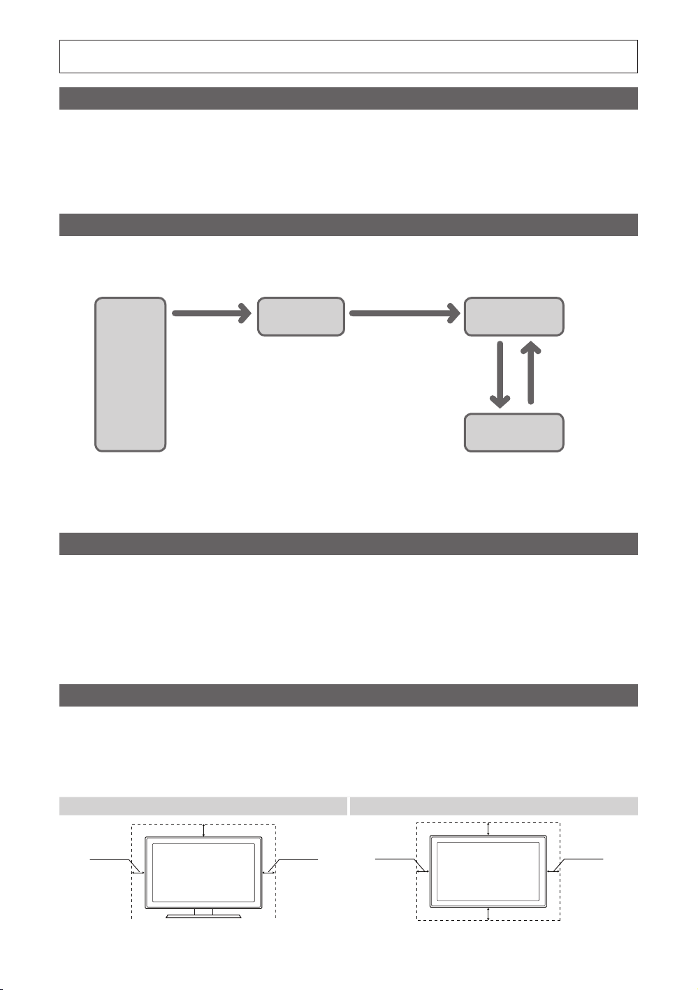
This TV is provided with interactive functionality through a set-back box (SBB/STB) connected to the TV, and with other TVs in a computercontrolled system for hotels and other hospitality businesses.
Interactive: When the TV is powered-up initially, it sends a command to identify the SBB/STB; if identified, the TV switches to ONLINE mode
and full control is through the SBB/STB.
If the TV is in ONLINE mode, it stops receiving IR(Samsung remote) commands and acts according to interface protocol.
Stand-Alone: If SBB/STB is not identified, the TV should be switched to STAND-ALONE mode with restricted operation.
Operational Modes
When this TV (in Hotel mode) is operated with a SBB/STB, it is in one of two states :
•ONLINE or STAND-ALONE. In the STAND-ALONE state, the TV will act as a Hotel TV, but without active communication. This is to prevent
guests from trying to cheat the system by disconnecting the SBB/STB.
Hotel TV
Hotel Mode On
Power
ON
To set the details for Stand-alone or interactive mode, refer to pages 22-25(Setting the hotel option data : Stand-alone mode and Interactive
mode)
•Some operations may be restricted to prevents guests from "cheating" the TV system.
•No main menu(Interactive mode) or Channel Menu, Plug & Play in Main Menu (Stand-Alone mode)
•Limited Volume and Panel key lock or unlock
SBB/STB Online if
one success within
10 attempts
Stand-alone Mode
SBB/STB
Online-10
consecutive
fails
Poll Rate 20/sec
SBB/STB
StatusAttempt every
2secs
Online Mode
Still image warning
Avoid displaying still images (like jpeg picture files) or still image element (like TV Program logo, panorama or 4:3 image format, stock or news
bar at screen bottom etc.) on the screen. Constant displaying of still picture can cause uneven wear of screen phosphor, which will affect
image quality. To reduce risk of this effect, please follow below recommendations:
•Avoid displaying the same TV channel for long periods.
•Always try do display any image on full screen, use TV set picture format menu for best possible match.
•Reduce brightness and contrast values to minimum required to achieve desired picture quality, exceeded values may speed up the burnout
process.
•Frequently use all TV features designed to reduce image retention and screen burnout. Refer to the relevant user manual section for details.
Securing the Installation Space
Keep required distances between the product and other objects (e.g. walls) to ensure proper ventilation.
Failing to do so may result in fire or a problem with the product due to an increase in the internal temperature.
•When using a stand or wall-mount, use parts provided by Samsung Electronics only.
– Using parts provided by another manufacturer may result in a problem with the product or injuries due to the product falling.
•The appearance may differ, depending on the product.
Installation with a stand. Installation with a wall-mount.
10 cm
10 cm10 cm
10 cm
10 cm
10 cm10 cm

Contents
y Accessories ............................................................................................................................................. 4
y Installing the LED TV Stand ...................................................................................................................... 5
y Viewing the Connection Panel .................................................................................................................. 7
y TV Controller ............................................................................................................................................ 10
y Viewing the Remote Control ..................................................................................................................... 11
y Samsung Smart Control ........................................................................................................................... 13
y Connecting the TV with SBB .................................................................................................................... 16
y Connecting the Bathroom Speakers ........................................................................................................ 17
y Connecting the MediaHub HD ................................................................................................................. 19
y Connecting the RJP (Remote Jack Pack) ................................................................................................. 20
y Setting the Hotel Option Data .................................................................................................................. 22
y Installing the Wall Mount .......................................................................................................................... 64
y Securing the TV to the Wall ...................................................................................................................... 65
y Anti-theft Kensington Lock ....................................................................................................................... 65
y Specifications .......................................................................................................................................... 66
y Dimensions .............................................................................................................................................. 67
ENGLISH
English
3
Accessories
✎ Please make sure the following items are included with your LED TV. If any items are missing, contact your dealer.
✎ The items’ colour and shapes may vary depending on the model.
• Remote Control & Batteries (AAA x 2)
• Samsung Smart Control & Batteries (AA x 2)
• Quick Set up Guide
• Power Cord / Data Cable
✎ The stand and stand screw may not be included, depending on the model.
✎ The Data Cable may not be included, depending on the SI Vendor.
• Owner’s Instructions
Safety Guide (Not available in all locations)
• Wall mount Adapter
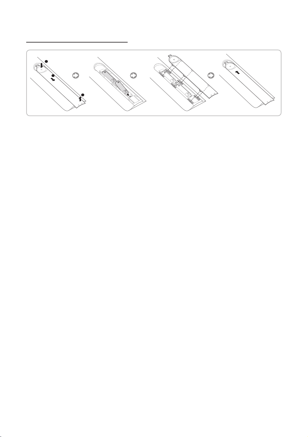
Installing the LED TV Stand
The 32” and larger LED TVs have swivel stands. You can set these stands so that the TVs swivel 20 degrees left and right or
90 degrees left and right.
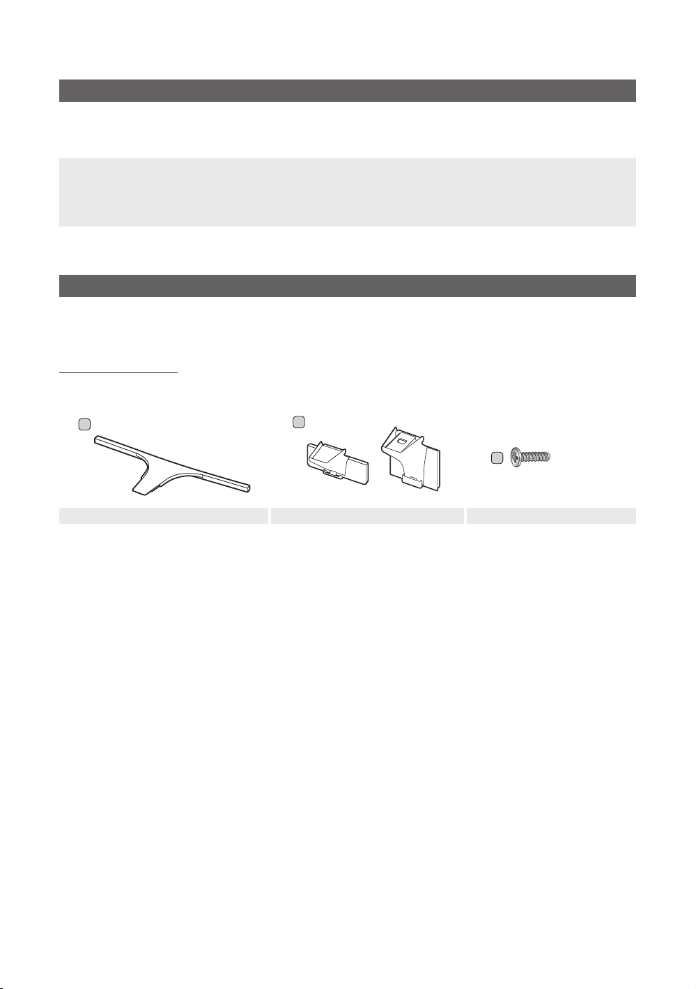
Stand Components
When installing the stand, use the provided components and parts.
B
A
1 EA
Stand Guide Stand Screws
1 EA
55" 65"
C
x8 (M4 X L14)
4
English
1
C
x4 (M4 X L14)
2
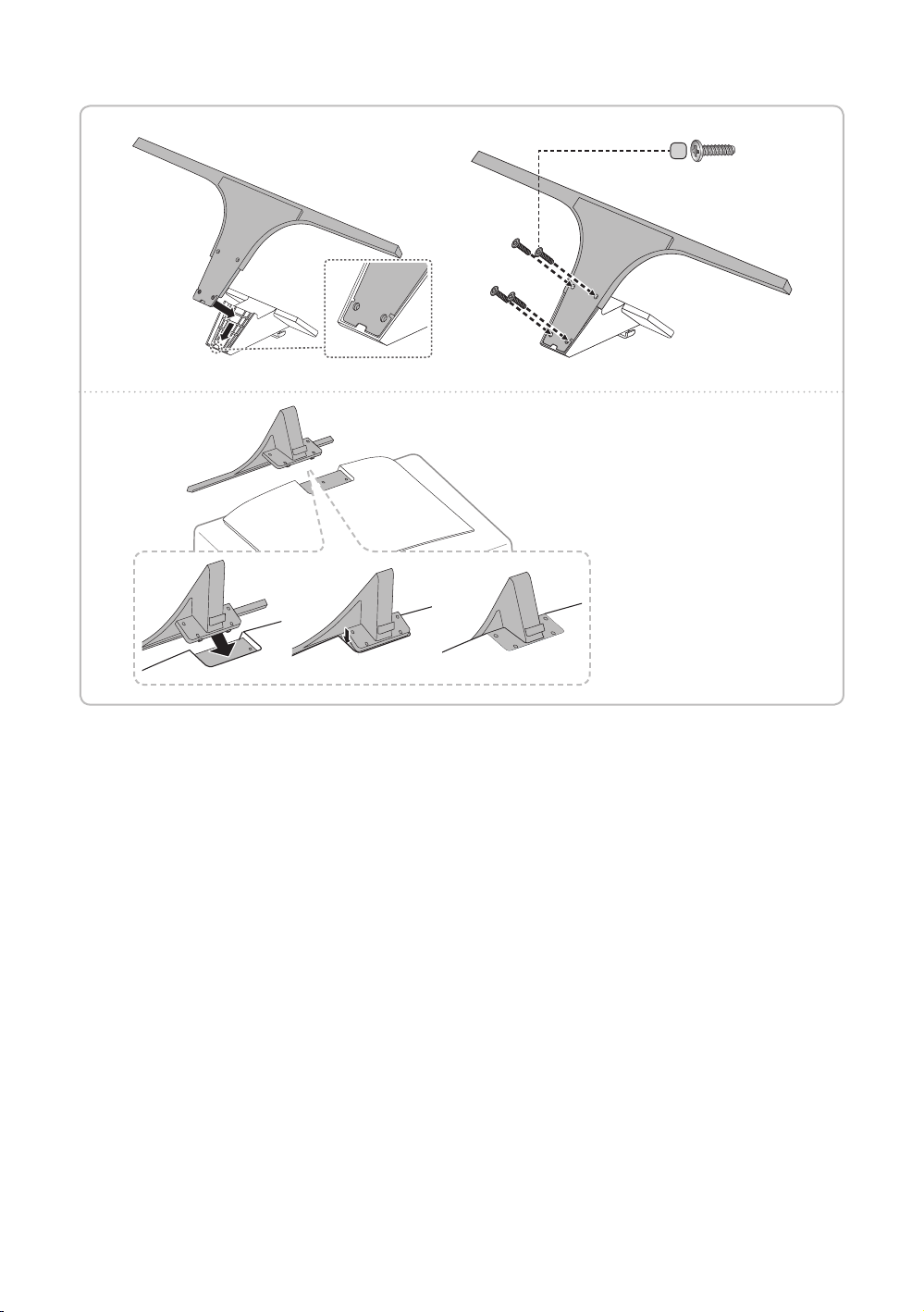
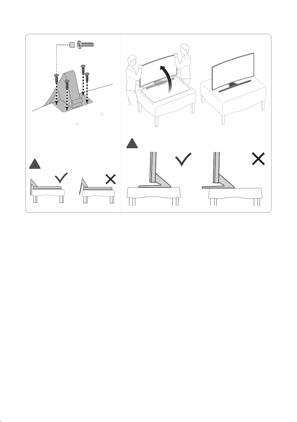
✎ Place a soft cloth over the
table to protect the TV, and
then place the TV on the
cloth screen-side down.
✎ Insert the Stand Guide into
the slot on the bottom of
th e T V.
✎ Slide and assemble it to the
end line in the direction of
arrow.
English
5
3 4
!
!
✎ Progress the assembly of screw in
the manual’s order.
C
x4 (M4 X L14)
✎ NOTE
• Make sure to distinguish between the front and back of each component when assembling them.
• Make sure that at least two persons lift and move the TV.
English
6
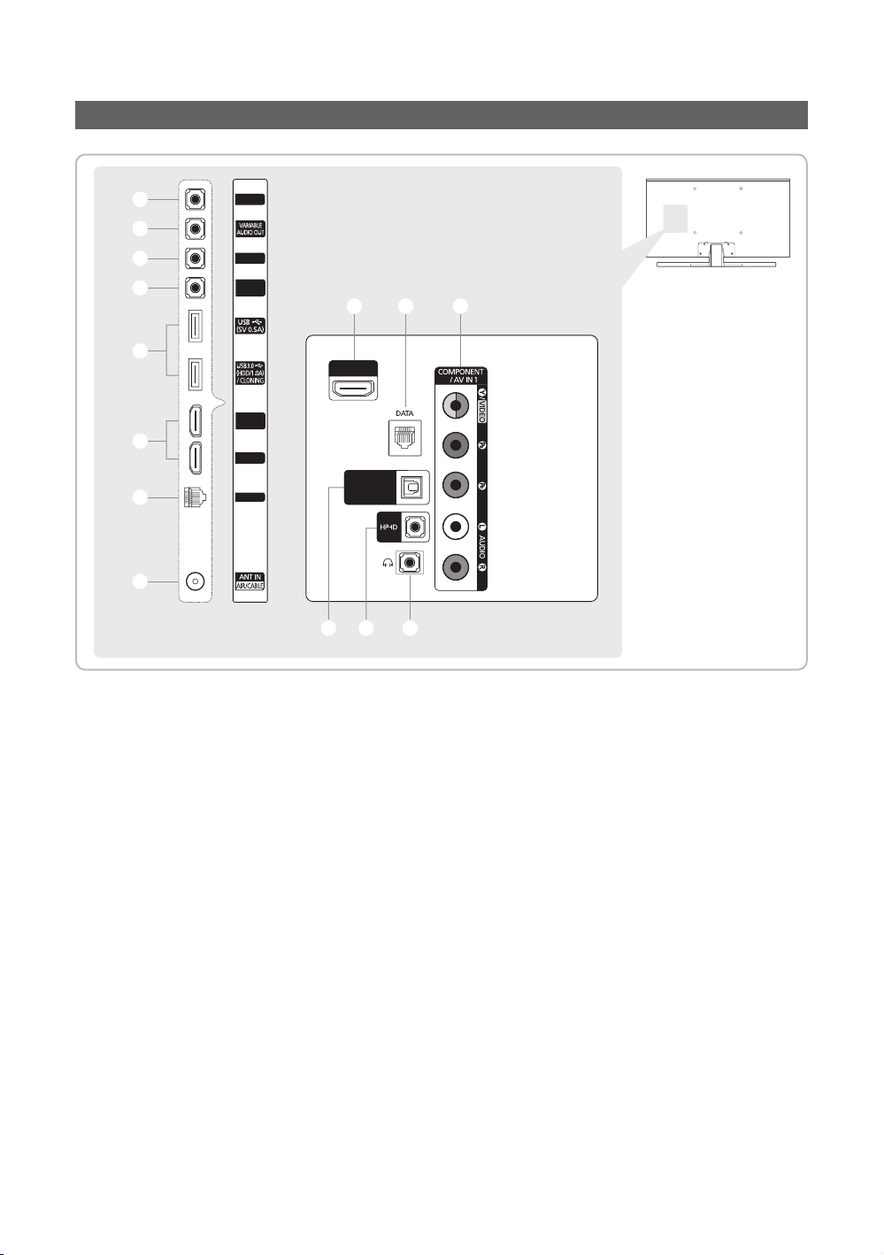
Viewing the Connection Panel
1
RJP
2
3
4
5
6
7
VOL-CTRL
DVI
AUDIO IN
HDMI IN 1
(DVI)
HDMI IN 2
LAN
6
HDMI IN 3
(ARC)
AUDIO OUT
(OPTICAL)
09
DIGITAL
8
#@!
✎ Whenever you connect an external device to your TV, make sure that power on the unit is turned off.
✎ When connecting an external device, match the colour of the connection terminal to the cable.
1
RJP
This port is an RJP (Remote Jack Pack) communication port that enables connecting different devices to additional
modules to improve device use and convenience.
2
VARIABLE AUDIO OUT
Used for the audio output to the Bathroom speaker. Connect the Bathroom Wall Box and the Variable port (RCA).
3
VOL-CTRL
Used to control the volume of the Bathroom speaker. Connect the Bathroom Wall Box and the VOLCTRL port.
4
DVI AUDIO IN
Connects to the audio input jacks on an Amplifier/Home Theatre.
5
USB (5V 0.5A), USB 3.0 (HDD/1.0A) / CLONING
– Connector for software upgrades and Media Play, etc.
– Service connection.
6
HDMI IN 1(DVI), 2, 3(ARC)
Connects to the HDMI jack of a device with an HDMI output.
✎ No sound connection is needed for an HDMI-HDMI connection. HDMI connections carry both audio and video.
✎ Use the HDMI IN 1(DVI) jack for a DVI connection to an external device. Use a DVI to HDMI cable or DVI-HDMI
adapter (DVI to HDMI) for the video connection and the DVI AUDIO IN jacks for audio.
✎ Use a cable shorter than 10 feet (3m) to get the best UHD viewing quality.
English
7

7
LAN
Connect to a wired LAN using CAT 7 cable.
8
ANT IN (AIR/CABLE)
– To view television channels correctly, the TV must receive a signal from one of the following sources:
– An outdoor antenna / A cable television system
9
DATA
– Used to support data communication between the TV and the SBB.
– Connects using RJ-12 TV type plugs.
0
COMPONENT/ AV IN 1
– Connect audio cables to "R-AUDIO-L" on your TV and the other ends to corresponding audio out jacks on an A/V
device.
– Connect RCA audio cables (optional) to "R - AUDIO - L" on the rear of the TV set and the other ends to
corresponding audio out jacks on the external device.
– When connecting to AV IN 1, the colour of the AV IN 1 [Y/VIDEO] jack (Green) does not match the colour of the
video cable (Yellow).
!
DIGITAL AUDIO OUT (OPTICAL)
Connects to a Digital Audio component.
@
HP-ID
Connect the cable to HP-ID and Headphone Jack simultaneously and connect it to separated Headphone Box. See
page 18. When connecting Headphone to Headphone Box, it works same as Headphone function.
#
HEADPHONE JACK
Headphones may be connected to the headphone jack on your TV. While the headphones are connected, the sound
from the built-in speakers is disabled.
Display Modes
You can also select one of the standard resolutions listed in the Resolution column. The TV will automatically adjust to the
resolution you choose.
After connecting a computer to the TV, set the screen resolution for the TV on the computer. The optimal resolution is 3840
x 2160 @ 60 Hz. If it is set to any other than in the table below, the TV may display nothing. Set the resolution properly,
referring to the user guide of the computer or its graphic card.
The resolutions in the table are recommended.
✎ Optimal resolution is 3840 x 2160 @ 60 Hz.
Mode Resolution
IBM 720 x 400 70 Hz 31.469 70.087 28.322 -/+
MAC
640 x 480
832 x 624
1152 x 870
Display
format
67 Hz
75 Hz
75 Hz
Horizontal
frequency (KHz)
35.000
49.726
68.681
Vertical frequency
(Hz)
66.667
74.551
75.062
Clock frequency
(MHz)
30.240
57.284
100.000
Polarity (horizontal
/ vertical)
-/-
-/-
-/-
8
English
Mode Resolution
Display
format
Horizontal
frequency (KHz)
Vertical frequency
(Hz)
Clock frequency
(MHz)
Polarity (horizontal
/ vertical)
VESA
DMT
CEA-861
640 x 480
640 x 480
640 x 480
800 x 600
800 x 600
800 x 600
1024 x 768
1024 x 768
1024 x 768
1152 x 864
1280 x 720
1280 x 800
1280 x 1024
1280 x 1024
1366 x 768
1440 x 900
1600 x 900RB
1680 x 1050
1920 x 1080
720(1440) x 576i
720(1440) x 480i
720 x 576
720 x 480
1280 x 720
1280 x 720
1920 x 1080i
1920 x 1080i
1920 x 1080
1920 x 1080
1920 x 1080
1920 x 1080
1920 x 1080
3840 x 2160
3840 x 2160
3840 x 2160
3840 x 2160
3840 x 2160
4096 x 2160
4096 x 2160
4096 x 2160
4096 x 2160
4096 x 2160
60 Hz
72 Hz
75 Hz
60 Hz
72 Hz
75 Hz
60 Hz
70 Hz
75 Hz
75 Hz
60 Hz
60 Hz
60 Hz
75 Hz
60 Hz
60 Hz
60 Hz
60 Hz
60 Hz
50 Hz
60 Hz
50 Hz
60 Hz
50 Hz
60 Hz
50 Hz
60 Hz
24 Hz
25 Hz
30 Hz
50 Hz
60 Hz
24 Hz
25 Hz
30 Hz
50 Hz
60 Hz
24 Hz
25 Hz
30 Hz
50 Hz
60 Hz
31.469
37.861
37.500
37.879
48.077
46.875
48.363
56.476
60.023
67.500
45.000
49.702
63.981
79.976
47.712
55.935
60.000
65.290
67.500
15.625
15.734
31.250
31.469
37.500
45.000
28.125
33.750
27.000
28.125
33.750
56.250
67.500
54.000
56.250
67.500
112.500
135.000
54.000
56.250
67.500
112.500
135.000
59.940
72.809
75.000
60.317
72.188
75.000
60.004
70.069
75.029
75.000
60.000
59.810
60.020
75.025
59.790
59.887
60.000
59.954
60.000
50.000
59.940
50.000
59.940
50.000
60.000
50.000
60.000
24.000
25.000
30.000
50.000
60.000
24.000
25.000
30.000
50.000
60.000
24.000
25.000
30.000
50.000
60.000
25.175
31.500
31.500
40.000
50.000
49.500
65.000
75.000
78.750
108.000
74.250
83.500
108.000
135.000
85.500
106.500
108.000
146.250
148.500
27.000
27.000
27.000
27.000
74.250
74.250
74.250
74.250
74.250
74.250
74.250
148.500
148.500
297.000
297.000
297.000
594.000
594.000
297.000
297.000
297.000
594.000
594.000
- / -
- / -
- / + / +
+ / +
+ / +
- / -
- / + / +
+ / +
+ / +
- / +
+ / +
+ / +
+ / +
- / +
+ / +
- / +
+ / +
- / -
- / -
- / -
- / + / +
+ / +
+ / +
+ / +
+ / +
+ / +
+ / +
+ / +
+ / +
+ / +
+ / +
+ / +
+ / +
+ / +
+ / +
+ / +
+ / +
+ / +
+ / +
✎ When using an HDMI/DVI cable connection, you must use the HDMI IN 1(DVI) jack.
✎ The interlace mode is not supported.
✎ The set might operate abnormally if a non-standard video format is selected.
✎ Separate and Composite modes are supported. SOG is not supported.
English
9
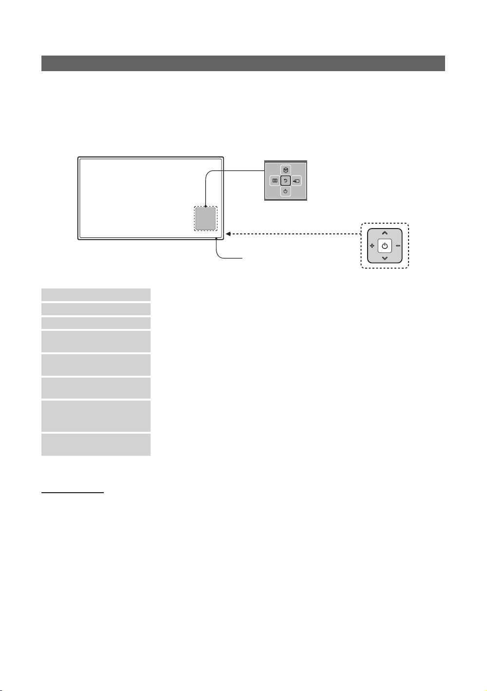
TV Controller
TV Controller is a multi directional button that helps navigate without using the remote control.
✎ Some functions which require a PIN code may not be available.
✎ The product colour and shape may vary, depending on the model.
✎ Exits the menu when pressing the controller for more than 1 second.
✎ When selecting the function by moving the controller to the up/down/left/right directions, do not press the controller. If
the controller is used first, you cannot operate it to move the up/down/left/right directions.
Function menu
TV Controller
The image is drawn by facing
the front side of the TV.
Remote control sensor
Power on Turn the TV on by pressing the controller in standby mode.
Adjusting the volume Adjust the volume by moving the controller from side to side when the power is on.
Selecting a channel Select a channel by moving the controller up and down when the power is on.
Using the function menu Press the controller when the power is on and the function menu appears. If you press
Using the Menu
Selecting the Source
Selecting the SMART HUB
( ™ )
Power Off
✎ To close the Menu, SMART HUB, or Source, press the Controller for more than 1 second.
it again, the function menu screen disappears.
Selects the MENU(m) by moving the controller in the function menu screen. The
OSD(On Screen Display) of your TV’s feature appears.
Selects the Source(s) by moving the controller in the function menu screen. The
Source list screen appears.
With the Function menu visible, select SMART HUB (™) by moving the Controller
upwards. The SMART HUB main screen appears. Select an application by moving the
Controller, and then pressing the Controller.
Selects the Power Off(P) to turn the TV off by moving the controller in the function
menu screen.
Standby mode
Do not leave your TV in standby mode for long periods of time a small amount of electric power is still consumed even when
the power button is such as when on holiday. off. It is best to unplug the power cord.
English
10
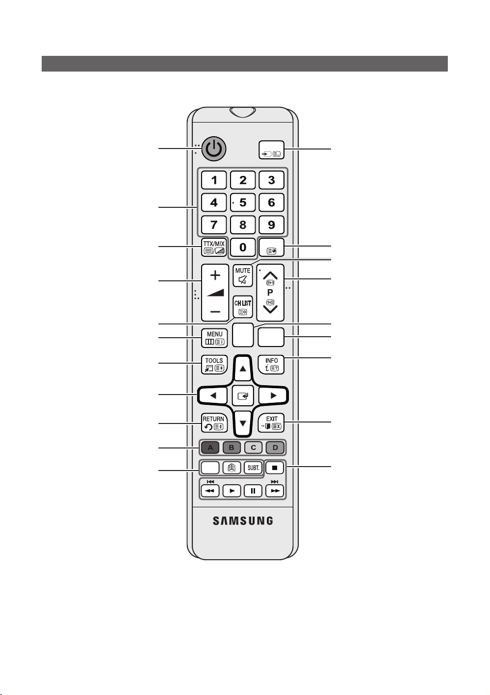
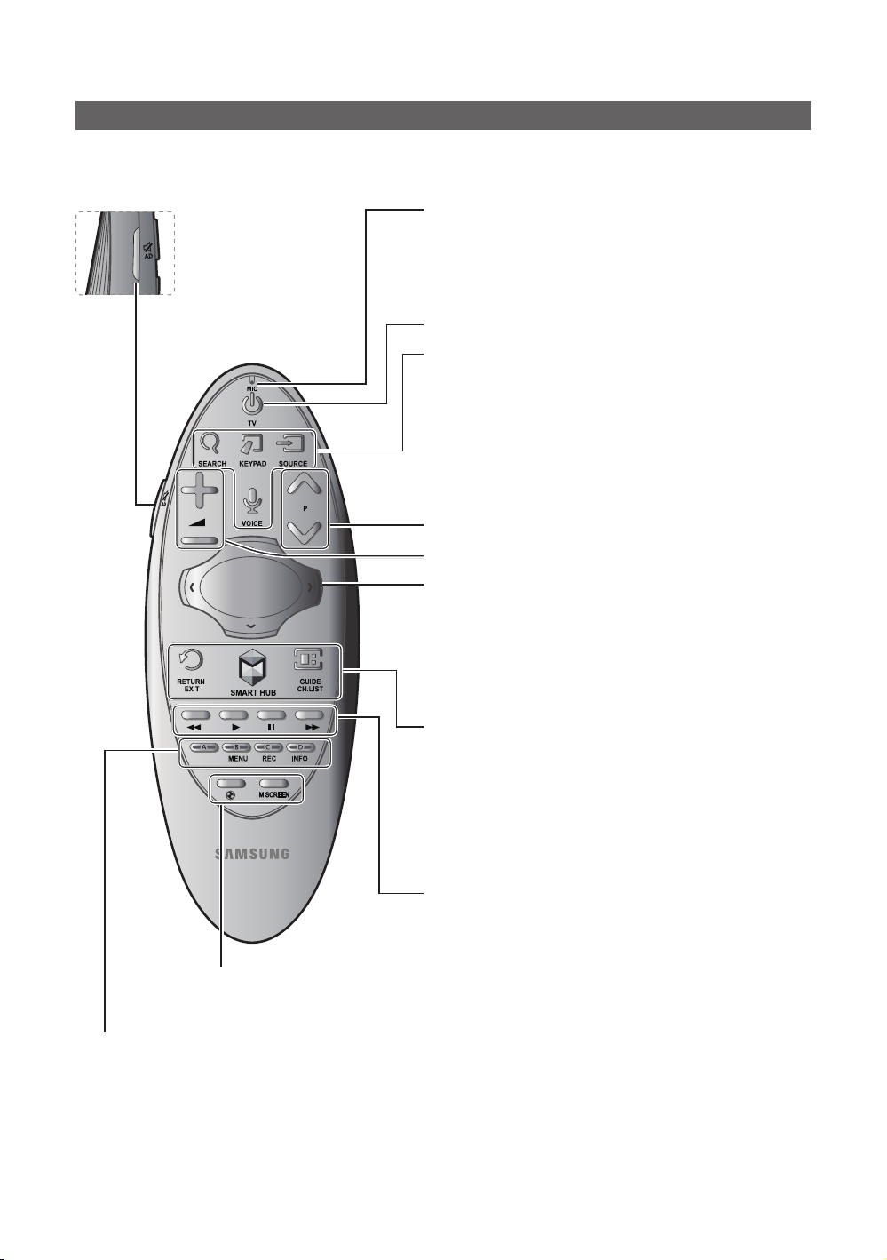
Viewing the Remote Control
✎ This remote control has Braille points on the
impaired persons.
Turns the TV on and off.
Have direct access to channels.
Alternately selects Teletext, Double
or Mix.
Adjust the volume.
Display channel list on the screen.
Display the main on-screen menu.
Quickly select frequently used
functions.
Select on-screen menu items and
change menu values.
Power, Channel
HOME
, and Volume buttons and can be used by visually
SOURCE
GUIDE
CONTENT
CLOCK
Display and select available video
sources.
Electronic Programme Guide (EPG)
display.
Cut off the sound temporarily.
Change channels.
Switch to the HOME Screen.
View the Contents Home.
Press to display information on the
TV screen.
CLOCK: When you press INFO key
in standby mode, TV screen displays
the time.
Return to the previous menu.
Buttons in the Channel list,
Contents Home menu, etc.
ALARM: Enter the hour you want the
TV to turn on.
X: Turns the 3D image on or off.
( Not available )
SUBT.: Displays digital subtitles.
ALARM
Exit the menu.
Use these buttons in the Contents
Home.
English
11
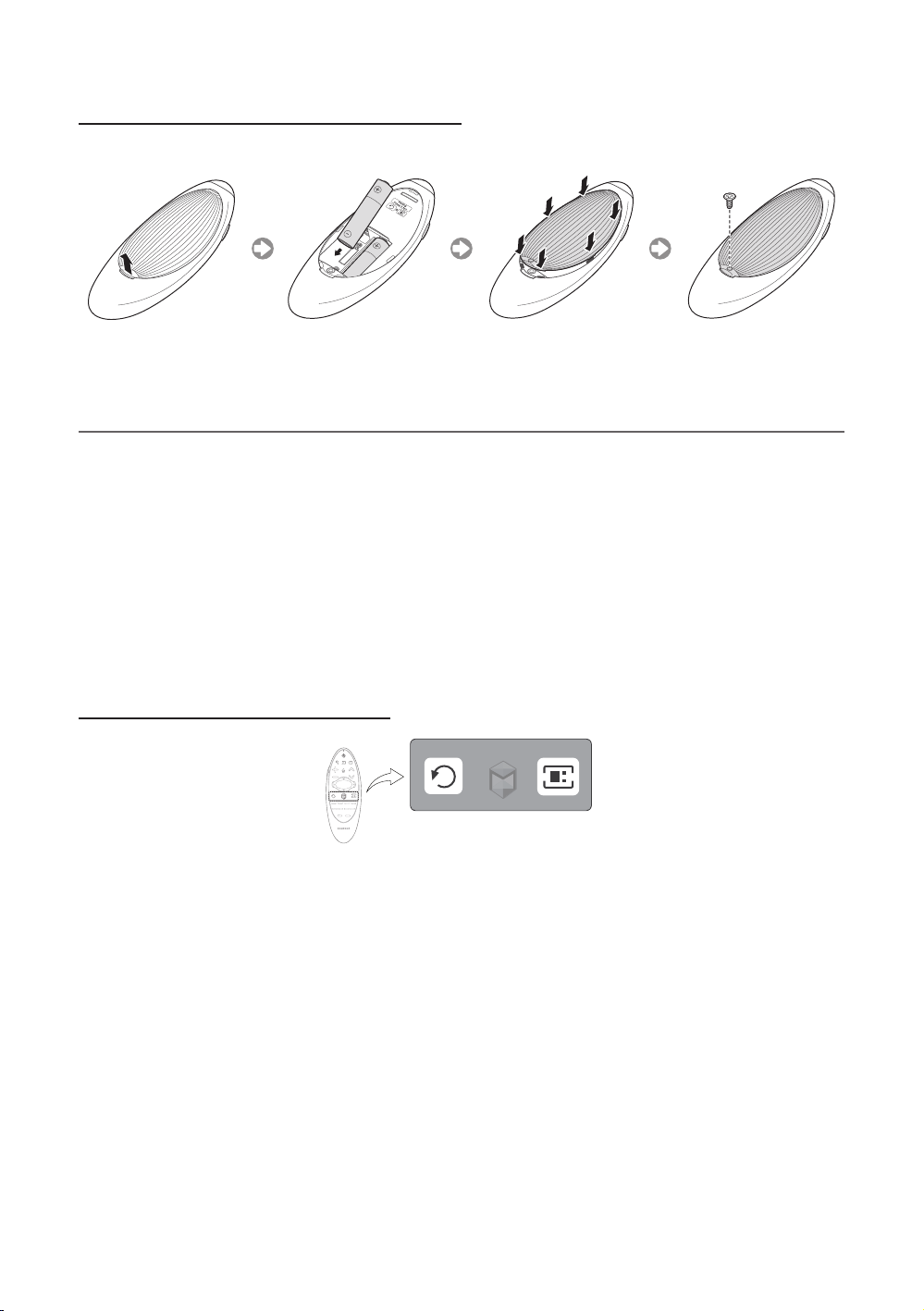
Installing batteries (Battery size: AAA)
X
Y
Z
✎ NOTE
• Use the remote control within 7m of the TV.
• Bright light may affect the performance of the remote control. Avoid using nearby special fluorescent light or neon
signs.
• The colour and shape may vary depending on the model.
• Remote control button 'HOME' & '3D' are not supported. When pressing these buttons, the TV unit does not
respond.
12
English
Samsung Smart Control
✎ Colours and shape may vary depending on the model.
¢: Turns the sound on/off.
AD: Press and hold this button
to bring up the Accessibility
Shortcuts panel. Select the
options to turn them on or off.
MIC: Use the microphone with the Voice Control and Voice functions.
– The Voice Control function can be af fected by unclear pronuncia-
tion, voice level, or surrounding noise.
Turns the TV on/off.
SEARCH: Press this button to use the search window. (Not available)
KEYPAD: With the virtual remote control on the screen, you can easily
enter digits, control content, and use functions.
SOURCE: Changes the source.
VOICE: Starts voice recognition. When the microphone icon appears on
the screen, say a voice command into the microphone. Say "Help" to
learn about basic usage and voice commands.
– Say a voice command 10cm to 15cm from the microphone and at
an appropriate volume.
Changes the channel.
Changes the volume.
– Touchpad: Place a finger on the touch pad and move the Samsung
Smart Control. The pointer on the screen moves in the direction
and as much as the Samsung Smart Control is moved. Press the
touchpad to run the focused item.
– < > ¡ £: Moves the pointer or focus.
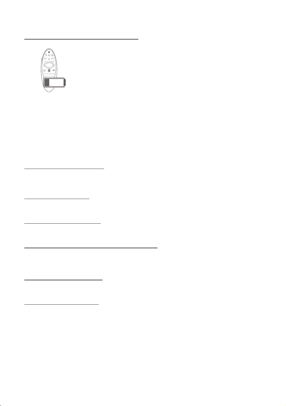
RETURN: Returns to the previous menu. Additionally, when you press
this button while watching TV, you can return to the previous channel.
EXIT: Press and hold this button to exit all currently running applications.
SMART HUB: Launches Smart Hub. Pressing SMART HUB while an
application is running terminates the application.
GUIDE: Displays the digital channel broadcasting schedule.
CH.LIST: Press and hold to launch the Channel List.
Use these buttons with specific features. Use these buttons according to
the directions on the TV screen.
¥:Enable Football Mode for an optimal sports viewing experience.
M.SCREEN: You can split the TV screen and use various functions such as watching TV, surfing the web, watching
video, and so on. For more information, refer to the e-Manual.
Colours button: Use these colour buttons to access additional options specific to the feature in use.
– MENU: Press and hold to display a menu on the screen.
– REC: Press and hold to record the broadcast.
– INFO: Press and hold to view information about the current digital channel or media file.
English
13
Inserting Batteries into Samsung Smart Control
To use Samsung Smart Control, first refer to the figure below and insert batteries into the unit.
Gently pull on the battery cover's notch and then remove the cover completely once it comes loose.
Insert 2 AA alkaline batteries, making sure to align the positive and negative polarities correctly.
¦ Using the Samsung Smart Control
Samsung Smart Control makes it even easier and more convenient to use the TV. Pressing the KEYPAD button displays a
virtual remote control that allows you to easily enter digits, control content, and activate functions on the screen.
– We recommend using Samsung Smart Control at a distance of less than 6m. A usable distance may differ depending
on the wireless environmental conditions.
Pairing the Samsung Smart Control
To control the TV with Samsung Smart Control, you need to pair Samsung Smart Control to the TV via Bluetooth. Pair
Samsung Smart Control to the TV.
– Samsung Smart Control can only be paired to a single TV.
Point Samsung Smart Control at the remote control sensor of the TV and press the TV button to turn the TV on.
– Remote control receiver’s location may vary depending on the model.
Reconnecting Samsung Smart Control
If the Samsung Smart Control stops operating or works abnormally, replace the batteries as this may be due to insufficient
battery power.
If the problem persists, the Samsung Smart Control restores pairing with the TV.
1. Press RETURN button and GUIDE button simultaneously for 3 seconds.
– You must place the Samsung Smart Control approximately 30cm ~ 40cm away from the T V and ensure it is
pointing towards the remote control receiver.
2. Connection image is appeared on the screen. And then, Samsung Smart Control is connecting to TV automatically.
English
14
When you see this alarm icon on the screen...
Following alarm icon indicates Samsung Smart Control's batteries are low. If the alarm
icon pops up, replace the batteries. Samsung recommends using alkaline batteries for a
longer operating life.
<Low battery Alarm Icon>
Using the TV by Moving the Samsung Smart Control
The Samsung Smart Control has a motion sensor (gyro sensor) that allows you to easily control the TV by holding and
moving the Samsung Smart Control.
After placing a finger on the touchpad, a pointer appears on the screen. Hold and move the Samsung Smart Control. The
pointer moves the same way the Samsung Smart Control is moved. It's also possible to scroll up and down on scrollable
screens.
– If you remove the finger from touchpad, the screen pointer disappears.
Using the TV with the Touchpad
Navigate to the Support menu and select the Smart Control Tutorial option to learn how to use the touchpad, following
the on screen instructions.
Moving the Focus/Pointer
Press the directional buttons (up, down, left, and right) to move the pointer or focus in the direction.
Menu Access & Item Selection
Press the touchpad. This lets you access a TV menu or select an item.
Displaying the Context-sensitive Menu on Smart Hub
Press and hold on the touch pad from the Smart Hub screen. The Options menu available to the selected item appears.
– The Options menu depends on the context.
Moving to the Smart Hub panel
On the Smart Hub screen, drag left or right on the touchpad. This will move the Smart hub panels left or right.
Scrolling on the Web Browser
Drag up/down on the touchpad in the web browser screen. This scrolls through the web screen.
English
15
Connecting the TV with SBB
DIGITAL
AUDIO OUT
(OPTICAL)
DIG
L
AUDIO OU
(
)
CON BCON A
1
6
6
1
STB SIDETV SIDE
CON A
6: NC
5: IR
4: GND
3: Rx
2: Tx
1: Nc
1: NC
2: GND
3: Rx
4: NC
5: Tx
6: IR
CON B
CON ACON B
65
24
53
32
TV Rear Panel
ETH MODEM
Data Cable
ITA
T
OPTICAL
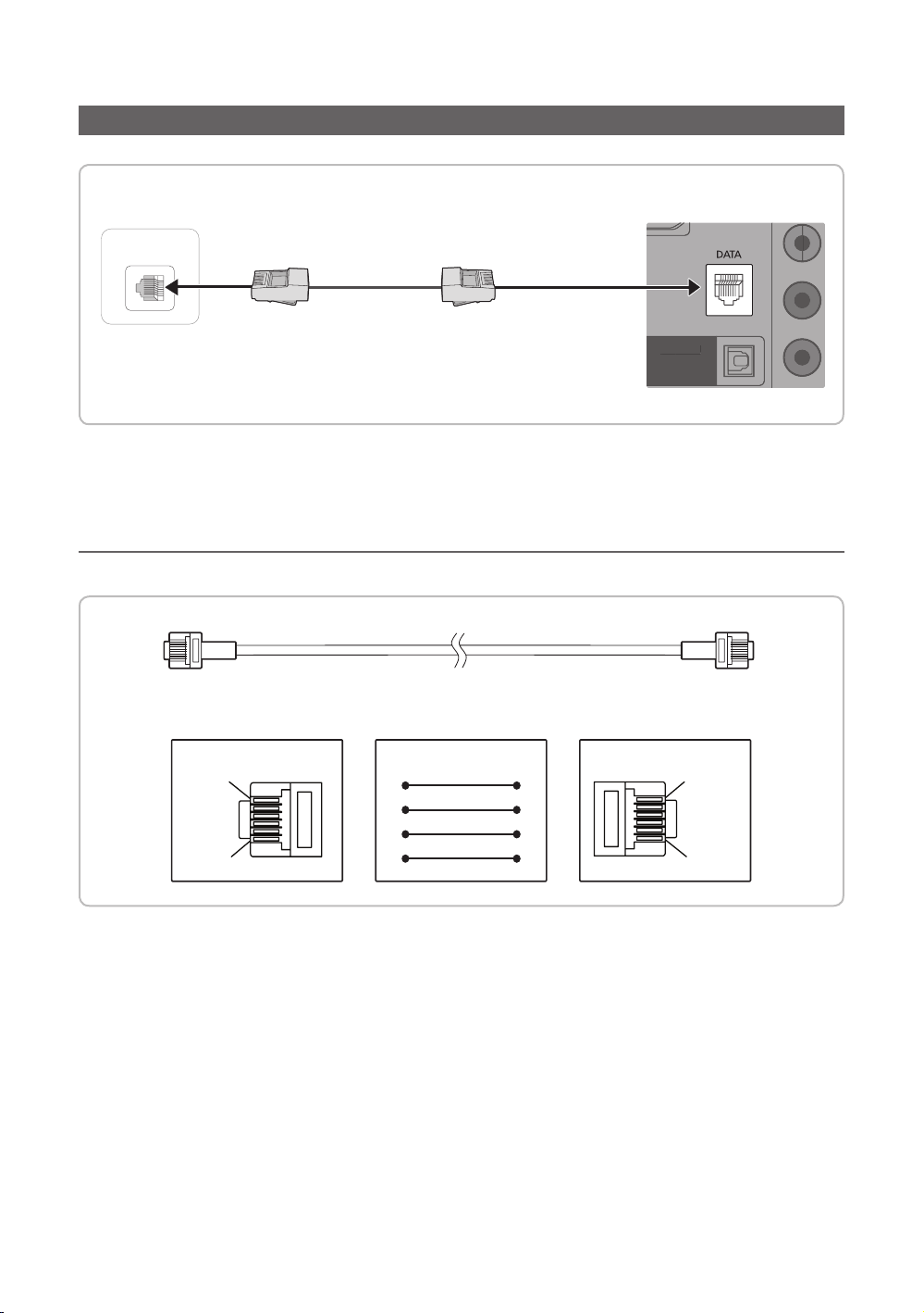
1. Connect the D ATA jack of the TV to the [ETH MODEM] jack of the STB (SBB) with the Data cable.
✎ Use data communication.
¦ List of Vendors and Compatible Data Cables Supplied with the TV
• Confirm that you are using the correct data cable for your vendor. Refer to the code label on the data cables.
16
English
Connecting the Bathroom Speakers
RJP
VOL-CTRL
DVI
AUDIO IN
RJP
DVI
AUDIO I
N
You can connect the Bathroom Speakers using the following method.
¦ Connecting through the Variable Output (available without an external amplifier)
TV Rear Panel
1
Speaker
2
VOL+
VOL
-
Volume
Control Box
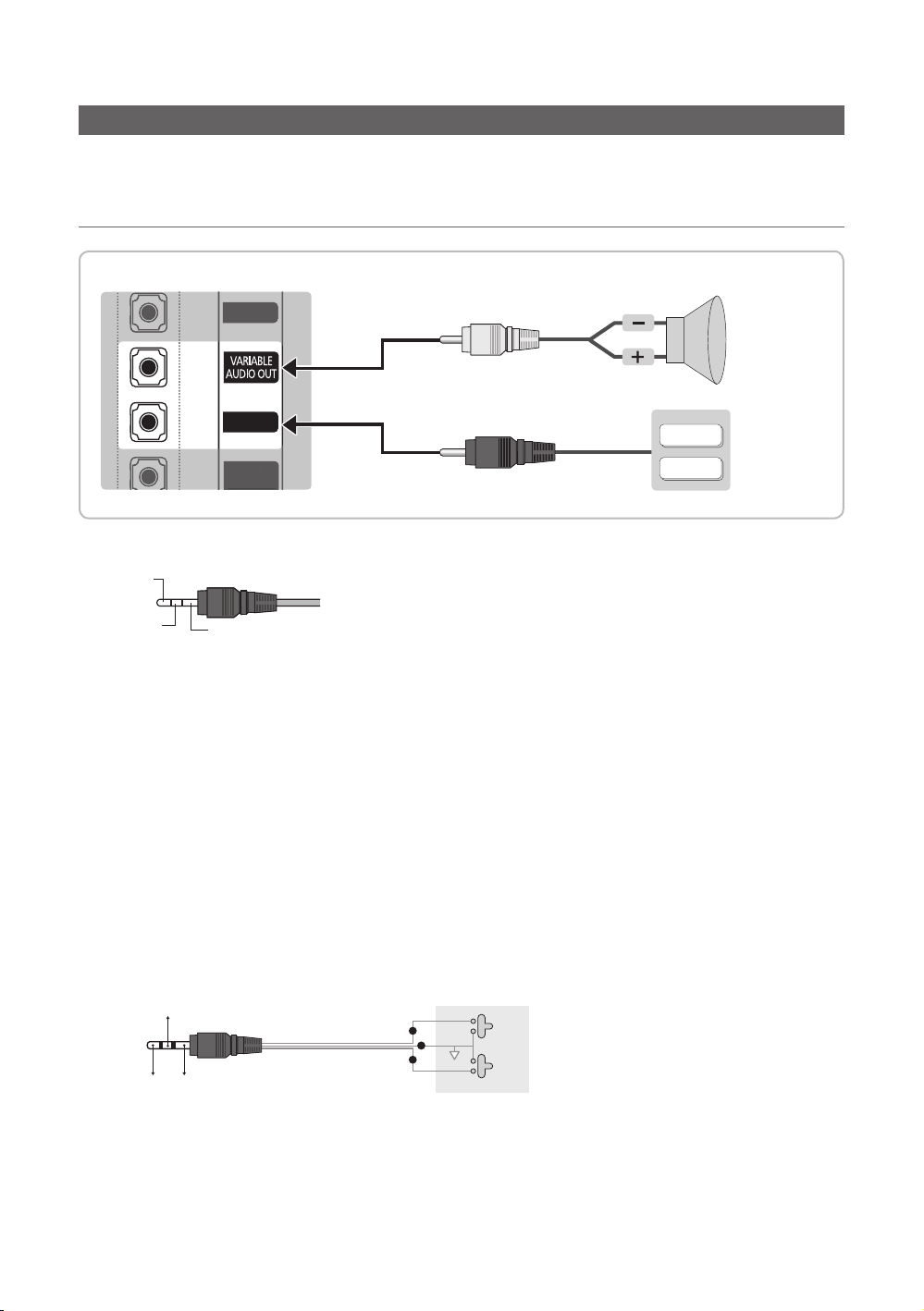
1. Connect the VARIABLE AUDIO OUT port of the TV to the Bathroom Wall Speakers of the hotel.
Speaker +
Speaker -
N/C
2. Connect the VOL-CTRL jack of the TV to the Volume Control Box Switch port on the Bathroom Wall of the hotel.
✎ The maximum speaker output is 4W, 8Ω.
✎ The VARIABLE AUDIO OUT port supports MONO sound out only.
• Installing the Volume Control
– If you configure the Volume Control Box as shown in the figure, you can control the volume of the bathroom
speakers.
– The jack that connects the Volume Control Box to the TV is a 3.5mm normal Phone jack.
– Volume Control Box switch is a Tact switch.
– Setting the Sub AMP Mode
– 0: Turns the Sub AMP function off (PWM off).
– 1: Determines the Sub volume according to the main volume control. the sub volume is determined according to
the Power On Volume, the Min Volume, and the Max Volume values of Hotel Mode.
– 2: Determines the volume according to the bathroom control panel setting.
• Variable Output Port Specifications
– Speaker Wire: Use speaker cable no more than 82 feet (25m) in length.
( Black /Red
VOL - DOWN
( White 1 )
VOL - UP
GND
( Shield Wire
2
)
3
)
Volume Control Box
1
3
2
VOL +
VOL
-
English
17
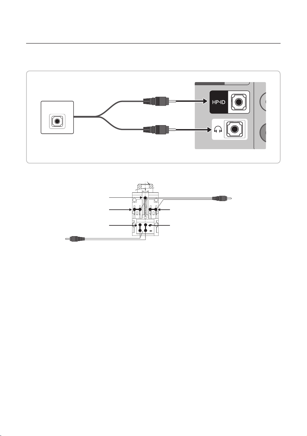
¦ Audio Loop In
An additional Headphone Box can be installed on a bed or business desk for added convenience. The installation
procedures are given below.
• Detailed Drawing of the Headphone Box.
TV Rear Panel
HEADPHON BOX
Headphone Box
TV HP-ID jack
Shield wire
Red Wire (Audio-R)
Red wire + White wire
TV Headphones jack
Whitewire (Audio-L)
Shield Wire
<Headphone Box>
18
English
Connecting the MediaHub HD
VOL-CTRL
LAN
D
AUDIO OU
(
)
Output to any external source connected to MediaHub HD on the hotel desk.
MediaHub HD Rear
USB RS/232
HDMI
RJP
1
RS-232
Data Cable
VOL-CTRL
DVI
AUDIO IN
AUDIO IN
VI
HDMI IN 3
(ARC)
TV Rear Panel
2
HDMI cable
HDMI IN 1
(DVI)
HDMI IN 2
LAN
DIGITAL
DIGITAL
AUDIO OUT
OPTICAL
(OPTICAL)
T
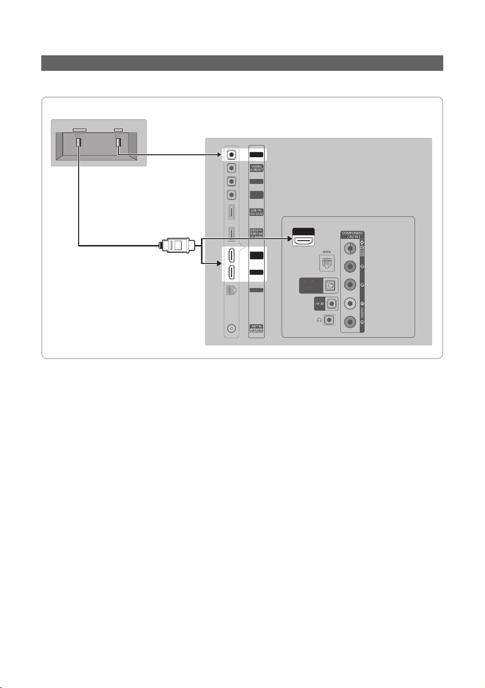
1. Connect the RJP port of the TV and the RS/232 port of the MediaHub HD.
2. Connect the HDMI IN 1(DVI), 2or 3(ARC) port of the TV and the HDMI port of the MediaHub HD.
•MediaHub HD
– The MediaHub HD is a hardware module that has different Audio Video inputs (A/ V, Audio, PC, HDMI and USB)
and corresponding outputs. The corresponding output sources connect from MediaHub to the TV. MediaHub
communicates with the TV via RS232. Hot Plug & Play is a function that allows hotel guests to connect an external
source to the MediaHub. MediaHub communicates with the TV by sending messages regarding Active/Inactive
sources. The TV switches to the Active external source.
– You have to connect the HDMI of the MediaHub to the HDMI IN 1(DVI) port of the T V.
– When the T V is on, connect the TV and the RJP within 10 seconds.
• Special features
– PIP
– Auto Detection
English
19
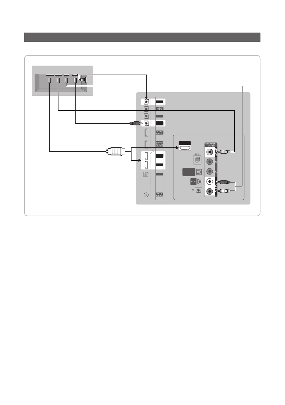
Connecting the RJP (Remote Jack Pack)
VOL-CTRL
LAN
DIG
AUDIO OU
(
)
Output to any exter nal source connected to RJP on the hotel desk.
RJP Rear
USB HDMI VIDEO
AUDIOAUDIO/PC
4
HDMI cable
RS/232
3
Video Cable
D-sub Audio cable
1
5
RJP
VOL-CTRL
DVI
AUDIO IN
HDMI IN 1
(DVI)
HDMI IN 2
LAN
HDMI IN 3
(ARC)
AUDIO OUT
(OPTICAL)
DIGITAL
ITAL
OPTICAL
2
T
Audio Cable
TV Rear Panel
1. Connect the DVI AUDIO IN port of the TV to the AUDIO port of the RJP.
2. Connect the AV IN 1 [VIDEO]/[L-AUDIO-R] port of the TV to the VIDEO port of the RJP.
3. Connect the AV IN 1 [VIDEO] port of the TV to the VIDEO port of the RJP.
4. Connect the HDMI IN 1(DVI), 2 or 3(ARC) port of the TV and the HDMI port of the RJP.
5. Connect the RJP port of the TV and the RS/232 port of the RJP.
✎ The RJP (Remote Jack Pack) compatible with this Samsung TV is TeleAdapt TA-7610, TA-7650 (HD) and TA-7660
(HD Plus).
• RJP (Remote Jack Pack): RJP stands for Remote Jack Pack. The RJP is a hardware module that has different Audio
Video inputs (A/V, Audio, PC and HDMI) and corresponding outputs. The corresponding output sources are connected
from RJP to TV. The RJP communicates with the TV via RS232. Hot Plug & Play is a function that allows hotel guests
to connect an external source to the RJP. The RJP communicates with the TV by sending messages regarding Active/
Inactive sources. The TV will switch to the Active external source according to the priority set by the User.
✎ You can select HDMI IN 1 (DVI), 2 or 3(ARC) and AV I N for connecting RJP.
✎ When the T V is on, connect the TV and the RJP within 10 seconds.
English
20
• The RJP can be returned to the factory default settings by pressing the A/V and HDMI buttons simultaneously for 10
seconds. All LEDs blink 5 times to acknowledge that this has been finished.
• The RJP will automatically turn off any LEDs after 5 minutes to avoid unnecessary light pollution in the hotel room. The
LEDs that were turned off will turn on again if the guest touches any of the buttons and the 5 minute timer will restart. If
the guest then touches another source button, the TV will change to the selected source and the corresponding LED will
be lit.
• After an RJP Reset or a TV Power OFF/ON, it takes approx. 10 seconds to establish communications between the TV
and the RJP.
• The following table shows the approximate time in seconds to switch from the TV to the input source, based on the
priority.
✎ Scenario 1: When no inputs are connected.
Source To Connect
AV 2 Sec
PC 0.7 Sec
HDMI 3.9 Sec
✎ Scenario 2: When two or more inputs are connected and an Input source is disconnected and then reconnected.
Source Disconnect To Connect Total
AV 4.5 Sec 2 Sec 6.5 Sec
PC 0.7 Sec 0.7 Sec 1.4 Sec
HDMI 3.9 Sec 3.9 Sec 7.8 Sec
✎ E.g. If the RJP has all its live sources AV, PC and HDMI connected, AV is viewed as the highest priority. If the RJP is
in HDMI mode, and a guest removes and reconnects the AV, the minimum time required to switch to the AV is 6.5
seconds.
• To connect audio (Ipod or Mp3), Music mode should be ON and Jack Ident detect should be OFF.
• A/V, PC and HDMI input sources are supported.
English
21
 Loading...