

Page 1

LED TV
Chassis : HAL51
Model : HG40ED590BB
SERVICE
Hospitality Displays Contents
1. Precautions
2. Product specications
3. Disassembly and Reassembly
4. Troubleshooting
5. Wiring Diagram
Manual
HG40ED590BB
Page 2

Contents
1. Precautions ...................................................................................................................1-1
1-1. Safety Precautions ..............................................................................................................1-1
1-1-1. Warnings ...................................................................................................................1-1
1-1-2. Servicing the LED TV ...............................................................................................1-1
1-1-3. Fire and Shock Hazard .............................................................................................1-1
1-1-4. Product Safety Notices ............................................................................................. 1-2
1-2. Servicing Precautions ..........................................................................................................1-3
1-2-1. General Servicing Precautions ................................................................................. 1-3
1-3. Static Electricity Precautions ...............................................................................................1-4
1-4. Installation Precautions .......................................................................................................1-5
2. Product Specications.................................................................................................2-1
2-1. Product information .............................................................................................................2-1
2-2. Product specication ...........................................................................................................2-2
2-2-1. Specications ...........................................................................................................2-2
2-2-2. Detailed Specications .............................................................................................2-3
2-3. Accessories ........................................................................................................................2-7
2-4. Viewing the Functions .........................................................................................................2-8
2-4-1. Hotel Plug & Play ...................................................................................................... 2-8
2-4-2. Hospitality mode option ............................................................................................2-9
3. Disassembly and Reassembly ....................................................................................3-1
3-1. Disassembly and Reassembly ............................................................................................3-1
3-1-1. TV Disassembly ........................................................................................................ 3-1
4. Troubleshooting ...........................................................................................................4-1
4-1. Previous Check ..................................................................................................................4-1
4-2. How to Check Fault Symptom .............................................................................................4-3
4-2-1.No Power ...................................................................................................................4-3
4-2-2. No Video (HDMI 1, 2 - Digital Signal) ......................................................................4-5
4-2-3. No Video (Tuner_CVBS) ..........................................................................................4-8
4-2-4. No Video ................................................................................................................. 4-11
4-2-5. No Sound (Speaker) ...............................................................................................4-14
4-3. Factory Mode Adjustments ................................................................................................4-17
4-3-1. Detail Factory Option ..............................................................................................4-17
4-3-2. Entering Factory Mode ...........................................................................................4-18
4-3-3. Factory Data ...........................................................................................................4-19
4-4. White Balance ...................................................................................................................4-35
4-4-1. Calibration ..............................................................................................................4-35
4-4-2. Service Adjustment ................................................................................................. 4-35
4-4-3. Adjustment .............................................................................................................. 4-37
4-5. RS-232C ............................................................................................................................4-38
4-6. Software Upgrade ..............................................................................................................4-39
4-6-1. Main SW Upgrade ..................................................................................................4-39
4-6-2. SUBMICOM Upgrade .............................................................................................4-41
Page 3

5. Wiring Diagram .............................................................................................................5-1
5-1. Wiring Diagram ....................................................................................................................5-1
5-2. Connector ............................................................................................................................5-2
5-3. Connector Functions ...........................................................................................................5-5
5-4. Cables .................................................................................................................................5-6
ANNEX. Exploded View & Part List [HG40ED590BBXEN JS01] ........................ ANNEX-1
1-1. Exploded View .......................................................................................................... ANNEX-1
1-1-1. Part List ......................................................................................................... ANNEX-1
2-1. Electrical Parts List ................................................................................................... ANNEX-2
Page 4

This Service Manual is a property of Samsung Electronics Co.,Ltd.
Any unauthorized use of Manual can be punished under applicable
International and/or domestic law.
© 2015 Samsung Electronics Co.,Ltd.
All rights reserved.
Printed in Korea
Page 5
3. Disassembly and Reassemble
3. Disassembly and Reassembly
This section of the service manual describes the disassembly and reassembly procedures for the LED TV.
This LED TV contains electrostatically sensitive devices. Use caution when handling these components.
WARNING
3-1. Disassembly and Reassembly
Disconnect the LED TV from the power source before disassembly.1.
Follow these directions carefully; never use metal instruments to pry apart the cabinet.2.
CAUTION
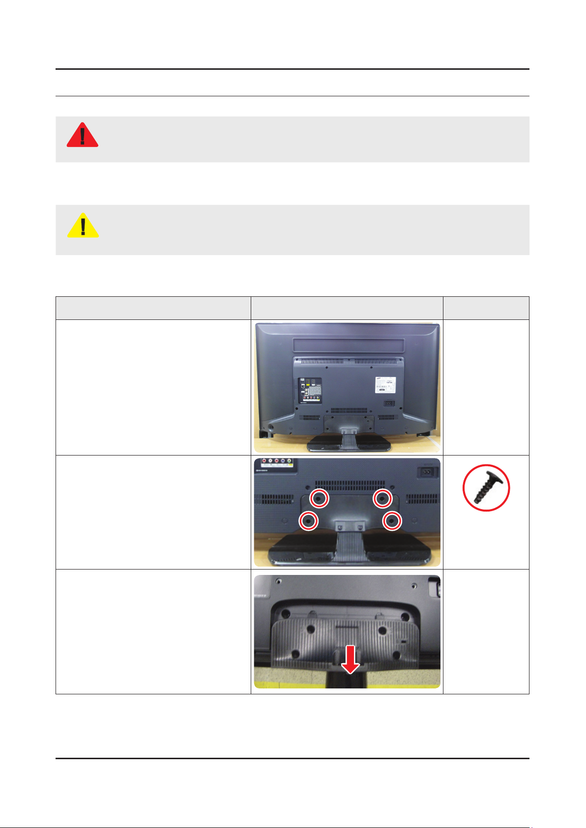
3-1-1. TV Disassembly
Place TV face down on cushioned table.
If there is no additional coment, it is same for all inches.3.
Description Picture Description Screws
1
Remove the screws from the ASSY
2
GUIDE P-STAND.
40" : 4EA•
Remove the ASSY STAND P-BASE.
3
6003-001782
SCREW-TAPTYPE
M4,L12,ZPC(BLK)
3-1
Page 6
3-2
3. Disassembly and Reassemble
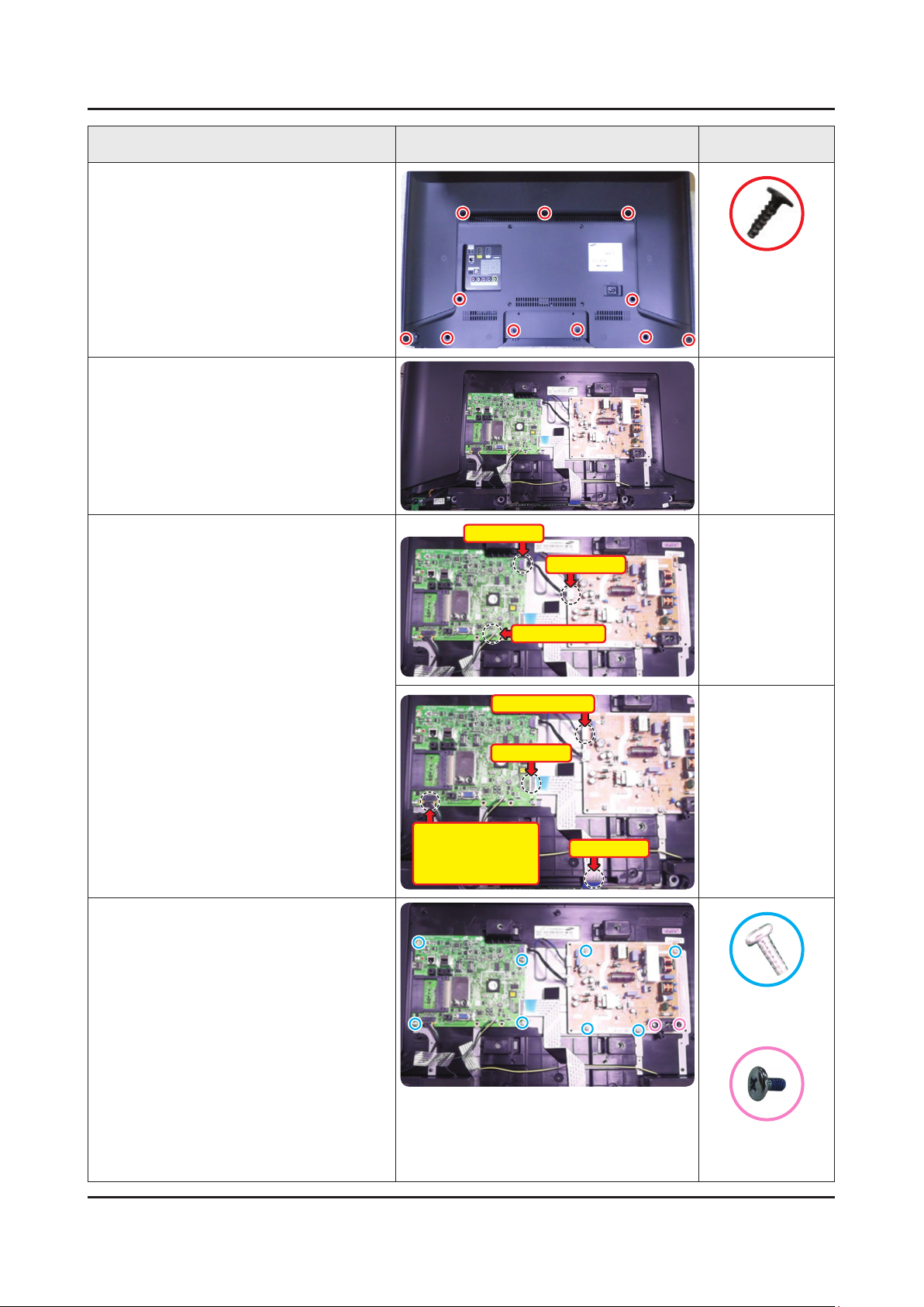
Description Picture Description Screws
Remove the screws from the ASSY
4
COVER P-REAR.
40" : 11EA•
Remove the ASSY COVER P-REAR.
5
6003-001782
SCREW-TAPTYPE
M4,L12,ZPC(BLK)
Remove the Power Cables and Speaker
6
Cables.
Remove the LVDS Cable, Panel Wire
Cable and ASSY BOARD P-JOG
SWITCH & IR & IR, NETWORK-WIFI
MODULE Cable.
Remove the 4 screws of ASSY PCB
7
MAIN.
Remove the 6 screws of DC VSS-LED
TV PD BD. (In this step, two types of
screws are used.)
Power Cable
Speaker Cable
Panel Wire Cable
LVDS Cable
ASSY BOARD P-JOG
SWITCH & IR /
NETWORK-WIFI
MODULE
Power Cable
LVDS Cable
6003-001856
SCREW-TAPTYPE
M4,L10,ZPC(WHT)
6001-003016
SCREW-MACHINE
M3.0,L5.0,ZPC(WHT)
Page 7

3-3
3. Disassembly and Reassemble
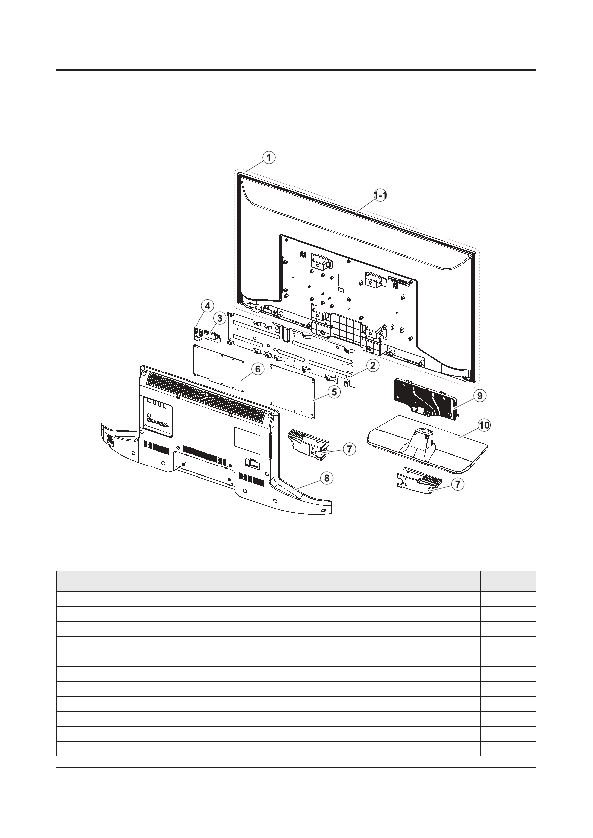
Description Picture Description Screws
Remove the ASSY SPEAKER (L/R).
8
Remove the screws of ASSY BOARD
9
P-JOG SWITCH & IR, NETWORK-WIFI
MODULE.
Completed disassembly.
10
Panel.•
NOTE
NETWORK-WIFI MODULE
6003-001856
SCREW-TAPTYPE
M4,L10,ZPC(WHT)
ASSY BOARD P-JOG SWITCH & IR
Reassembly procedures are in the reverse order of disassembly procedures.
Page 8
ANNEX. Exploded View & Part List
ANNEX. Exploded View & Part List [HG40ED590BBXEN JS01]
1-1. Exploded View
1-1-1. Part List
No. Code No. Description & Specication Q’ty SA/SNA Remark
1 BN95-01875A PRODUCT LCD-INX; CY-HH040BGNV1V/H,Mega,Bl 1 SA
1-1 BN96-34244A ASSY CHASSIS TOP P; MEGA 40,PC+ABS+G/F15 1 SA
2 BN61-10765B BRACKET-PCB; H4203,EGI-SECC,T0.5 1 SNA
3 BN59-01174A NETWORK-WIFI MODULE; WIDT-30Q,Internal Wi 1 SA
4 BN96-35791A ASSY BOARD P-JOG SWITCH & IR; hotel_HD470 1 SA
5 BN94-08837F ASSY PCB MAIN; HOTEL 1 SA
6 BN44-00757A DC VSS-LED TV PD BD; L48G0B_ESM,L48G0B_ES 1 SA
7 BN96-32738C ASSY SPEAKER P; 6ohm,10W,holderless_PDP-r 1 SC
8 BN96-34361L ASSY COVER P-REAR; HD590,EUROPE,PC+ABS , 1 SA
9 BN61-09997A GUIDE-STAND; UH5000 40",PC+GF20%,V2 1 SC
10 BN96-31506A ASSY STAND P-BASE; UH5500 40",PC+ABS+G/F2 1 SA
ANNEX-1
Page 9

ANNEX-2
ANNEX. Exploded View & Part List
2-1. Electrical Parts List
Service Bom (SA: SERVICE AVAILABLE, SNA: SERVICE NOT AVAILABLE)
Level Location No. Code No. Description & Specication Q’ty SA/SNA Remark
HG40ED590BBXEN (JS01)
1 S001A BN90-05205C ASSY STAND;UH5K 1 SNA
0.2 SG03 BN61-09997A GUIDE-STAND;UH5000 40",PC+GF20%,V2 1 SC
..3 0103-007285 RESIN PC;HF3200H,K21294,BK0007,V2 250
0.2 SB04A BN96-31506A ASSY STAND P-BASE;UH5500 40",PC+ABS+G/F2 1 SA
..3 CCM1 BN63-04755B SHEET-COVER;AMBER,PE,T0.05,W200mm,200M,C 1 SNA
..3 BN63-11633A COVER-STAND BASE;UH5500 40",PC+ABS+G/F20 1 SNA
...4 0103-009946 RESIN PC ABS;HM-1200,BLACK,BK0007,V1 670 SNA
..3 BN67-00327D RUBBER-FOOT;STAND,SILICON,13*13,T2,GRAY( 6 SNA
..3 BN69-08751B WRAP VINYL-SHRINK;STAND,PLASTIC OTHERS,P 1 SNA
1 R001A BN90-07491A ASSY COVER REAR;HD590 1 SNA
0.2 SCREW 6003-001782 SCREW-TAPTYPE;BH,+,B,M4,L12,ZPC(BLK),SWR 11 SA
0.2 R001A BN96-34361L ASSY COVER P-REAR;HD590,EUROPE,PC+ABS ,V 1 SA
..3 AA63-01638A FELT;50P9,FELT,0.5,15,40,NTR 4 SNA
..3 R001 BN63-13941F COVER-REAR;D590 40",ABS+PC,BLK,V1,EO 1 SNA
...4 0103-010376 RESIN PC ABS;FR3012 / 901510,BLACK,BK000 780 SNA
1 BN91-13535A ASSY LCM-INX;BN95-01875A,CY-HH040BGNV1V 1 SNA
0.2 PANEL BN95-01875A PRODUCT LCD-INX;CY-HH040BGNV1V/H,Mega,Bl 1 SA
..3 BN02-00114C TAPE PET-COF;LCM all model,PET,0.07T,20, 4 SNA
..3 BN60-00667C SPACER-GASKET;Y13 SF-LED,GASKET(FG200A), 2 SNA
..3 BN68-05722A LABEL-STICKER;ALL MODEL,POLYPROPYLENE,0. 1 SNA
..3 BN90-06228A ASSY MISC-BLU;Mega FHD 40 1 SNA
...4 BN61-08161A HOLDER-LED-PCB;Direct-LED,PC,white 19 SNA
....5 0103-009493 RESIN PC;LH-1070W,W92853,WT0107,V-0 19 SNA
...4 BN61-11123A SUPPORT-PLATE;MEGA,PC,CLEAR 3 SNA
....5 0103-005036 RESIN PC;M2407,550115,TP0003 11 SNA
...4 BN61-11258A LGP-DIFFUSESR PLATE;39.5inch, A type Meg 1 SNA
...4 BN63-13083A SHEET-COMPLEX;MEGA2 39.5, DMOP-4R,PET,0. 1 SNA
...4 BN63-13084A SHEET-REFLECTOR;MEGA2 39.5, UXJP175 / DJ 1 SNA
...4 BN96-34174A ASSY LED BAR P-LED BAR;39.5" Mega U/D,13 2 SNA
...4 BN96-34175A ASSY LED BAR P-LED BAR;39.5" Mega mid,12 1 SNA
...4 BN96-34242A ASSY FRAME P-MOLD MIDDLE;MEGA 40",PC+G/F 1 SNA
....5 BN60-00928E SPACER-D PLATE A;H5200, 40",PET,155,BLK, 4 SNA
....5 BN60-00928F SPACER-D PLATE B;H5200, 40",PET,223,BLK, 3 SNA
....5 BN60-00928G SPACER-D PLATE C;H5200, 40",PET,175,BLK, 1 SNA
....5 BN60-00928H SPACER-D PLATE D;40H5200,PET,192,BLK,T0. 4 SNA
....5 BN60-00999S SPACER-PANEL U;H5200, 40",SI,835.0,GRAY, 1 SNA
....5 BN60-00999T SPACER-PANEL D;H5200, 40",SI,820,GRAY,T0 1 SNA
....5 BN60-00999U SPACER-PANEL LR;H5200, 40",SI,500.0,GRAY 2 SNA
....5 BN60-00999Z SPACER-D-PLATE;ALL-MODEL,SI,55,Gray,T0.5 1 SNA
....5 BN61-11182A FRAME-MOLD MIDDLE;Y14 F-LED 39.5",PC+GF1 1 SNA
.....6 0103-007368 RESIN PC;LS-3104G,K2495,BK0048,3.0mm V-2 100 SNA
...4 BN96-34243A ASSY CHASSIS BOTTOM P;MEGA 40",PC+ABS+G/ 1 SNA
....5 0203-001598 TAPE-FILAMENT;#8915,0.15,12,55000,CLR 0 SNA
Page 10

ANNEX-3
ANNEX. Exploded View & Part List
Level Location No. Code No. Description & Specication Q’ty SA/SNA Remark
....5 SCREW 6003-000117 SCREW-TAPTYPE;BH,+,B,M3,L6,ZPC(WHT),SWRC 4 SNA
....5 SCREW 6003-001070 SCREW-TAPTYPE;BH,+,B,M2,L4,ZPC(BLK),SWRC 6 SA
....5 SCREW 6003-001782 SCREW-TAPTYPE;BH,+,B,M4,L12,ZPC(BLK),SWR 4 SA
....5 M0909 AA63-01388A GASKET-EMI,SPONGE;SP-P300M,Conductive Fa 1 SA
....5 BN02-00040P TAPE DOUBLE FACE-D-PLATE;F-LED ALL,PET,0 2 SNA
....5 BN02-00102B TAPE-FILAMENT;#8917,0.15,25,50,WHITE 0 SNA
....5 BN02-00352D TAPE OPP;PET,T0.05,W20,L50M,BLK,ULNO.E16 0 SNA
....5 EC13 BN39-01908A LEAD CONNECTOR;40inch Mega,Lead Connecto 1 SNA
....5 BN60-01009F SPACER-LINK;Y14 ENTRY MODEL,CONDUCTIVE F 2 SNA
....5 BN60-01051A SPACER-THERMAL RADIATION;Y14 ENTRY MODEL 4 SNA
....5 BN61-10607A BRACKET-LED BAR_U;Y14 F-LED 40" (MEGA),A 2 SNA
....5 BN61-10610A BRACKET-LED BAR_D;Y14 F-LED 40" (MEGA),A 1 SNA
.....6 0102-001955 ALUMINUM PLATE;A5052,H32,T0.5,790 0 SNA
....5 BN61-10731A BRACKET-WALL MOUNT;MEGA,EGI-SECC AG,T1.2 4 SNA
....5 BN61-11183A BRACKET-EMI_L;Y14 F-LED 39.5" (MEGA),EGI 1 SNA
....5 BN61-11184A BRACKET-EMI_R;Y14 F-LED 39.5" (MEGA),EGI 1 SNA
....5 BN61-11318A BRACKET-EMI_A;Y14 F-LED 39.5" (MEGA),EGI 1 SNA
....5 BN61-11319A BRACKET-EMI_B;Y14 F-LED 39.5" (MEGA),EGI 1 SNA
....5 BN63-07349A GASKET;GASKET EMI,Polyurethane Sponge+ P 3 SNA
....5 BN63-08831A GASKET;GASKET EMI,Polyurethane Sponge+ P 1 SNA
....5 CC02 BN64-02831A CHASSIS-BOTTOM;Y14 F-LED 39.5" (MEGA),PC 1 SNA
.....6 0103-010275 RESIN PC ABS;235GNH15/6919H,Black,BK0007 2300 SNA
....5 M0131 MD63-00103A GASKET;GRANDSLAM,Conductive Fabric,1,10, 2 SNA
..3 BN96-33321A ASSY OPEN CELL;V400HJ6-PE1,V400HJ6-PE1,1 1 SNA
...4 BN81-10993A A/S-A/S-IC DRIVER SOURCE;INX 39.5 FHD 60 1 SNA
...4 BN81-10994A A/S-A/S-IC DRIVER GATE;INX 39.5 FHD 60Hz 1 SNA
...4 BN81-10995A A/S-ASSY PCB-SOURCE (XL);INX 39.5 FHD 60 1 SNA
...4 BN81-10996A A/S-ASSY PCB-SOURCE (XR);INX 39.5 FHD 60 1 SNA
...4 BN81-10997A A/S-POLARIZER-C/F;INX 39.5 FHD 60Hz,4101 1 SNA
...4 BN81-10998A A/S-POLARIZER-TFT;INX 39.5 FHD 60Hz,4101 1 SNA
..3 TC01A BN96-34244A ASSY CHASSIS TOP P;MEGA 40,PC+ABS+G/F15% 1 SA
...4 BN02-00112A TAPE ETC-ALL;POLYESTER,L65.8M,T0.009,W10 0 SNA
...4 BN60-00715A SPACER-TOP,CORNER;Y13 Slim F-LED,GASKET* 4 SNA
...4 BN60-01009E SPACER-LINK;Y14 ENTRY MODEL,CONDUCTIVE F 2 SNA
...4 BN60-01070B SPACER-TOP LR;MEGA 39.5",CONDUCTIVE FABR 2 SNA
...4 BN60-01070C SPACER-TOP UD;MEGA 39.5",CONDUCTIVE FABR 2 SNA
...4 AS080 BN63-07556T SHEET-COVER;TOC,PUR,T0.07,W22mm,100M,ST- 1 SNA
...4 AS080 BN63-10945D SHEET-COVER;Y13 SF-LED,PO-SHEET,T0.068,W 1 SNA
...4 BN63-11875A SHEET-COVER;Y14 SF-LED,POLY*,0.068,W25,L 2 SNA
...4 AC157 BN64-02832A CHASSIS-TOP;Y14 F-LED 39.5" (MEGA),PC+AB 1 SNA
....5 0103-010275 RESIN PC ABS;235GNH15/6919H,Black,BK0007 190 SNA
1 M0017 BN91-15292F ASSY CHASSIS;HOTEL 1 SNA
0.2 M0014 BN94-08837F ASSY PCB MAIN;HOTEL 1 SA
..3 0202-001608 SOLDER-WIRE FLUX;LFC7-107,D0.8,99.3Sn/0. 1 SNA
..3 BN62-00273B HEAT SINK-PS;TV Echo-P,A6063,5t,BLACK,40 1 SNA
..3 BN97-09912F ASSY SMD;HOTEL 1 SNA
...4 0202-001830 SOLDER-CREAM;LFM-48W TM-HP,D20~38um,96.5 1 SNA
Page 11

ANNEX-4
ANNEX. Exploded View & Part List
Level Location No. Code No. Description & Specication Q’ty SA/SNA Remark
...4 DS01A 0401-001056 DIODE-SWITCHING;MMBD4148SE,100V,200mA,SO 5 SA
...4 DS01A 0401-001099 DIODE-SWITCHING;1N4148WS,75V,150mA,SOD-3 2 SA
...4 DR01A 0402-001614 DIODE-RECTIFIER;S1G,400V,1A,DO-214AC,TP 1 SA
...4 0403-001783 DIODE-ZENER;BZB84-C6V2,5.8/6.6V,300mW,SO 6 SNA
...4 0404-001089 DIODE-SCHOTTKY;RB551V-30,20V,500MA,SOD-3 1 SA
...4 0404-001404 DIODE-SCHOTTKY;BAT721C,40V,200mA,SOT-23, 3 SA
...4 0404-001881 DIODE-SCHOTTKY;SS3040-HE,40V,3000mA,SOD- 3 SA
...4 0406-001200 DIODE-TVS;RCLAMP0504F,6/-/-V,150W,SC-70 2 SA
...4 0406-001290 DIODE-TVS;3.0SMCJ20A,22.2/-/24.5V,3000W, 1 SNA
...4 0406-001628 DIODE-TVS;AOZ8804ADI,6/-/-V,150W,SLP2510 1 SA
...4 0406-001635 DIODE-TVS;SMF5.0A,6.4V, 6.7V, 7V,200W,SM 10 SA
...4 DS01A 0407-000114 DIODE-SWITCHING;KDS184,80V,100mA,SOT-23, 1 SNA
...4 0501-000445 TR-SMALL SIGNAL;KTC3875S-Y,NPN,150mW,SOT 4 SC
...4 0505-002560 FET-SILICON;AO6415,P,-20V,-3.3A,0.15ohm, 1 SA
...4 0505-002598 FET-SILICON;AP2317GN,P,-20V,-4.2A,0.052o 1 SA
...4 0505-002893 FET-SILICON;AO4801AS,P,-30V,-5A,2W,SOIC- 1 SA
...4 0505-002917 FET-SILICON;AO3406,N,30V,3.6A,1.4W,SOT-2 2 SA
...4 0505-003397 FET-SILICON;2N7002K,N,60V,380mA,1.19ohm, 5 SA
...4 0801-002780 IC-CMOS LOGIC;74LVC1G17,SCHMITT-TRIGGER 3 SA
...4 0801-003330 IC-CMOS LOGIC;Octal buffer,DQFN,20P,4.5x 1 SA
...4 0909-001032 IC-REAL TIME CLOCK;PCF8563,SOP,8P,4.9x3. 1 SA
...4 1006-001509 IC-DRIVER/RECEIVER;MAX3222ECPWR,TSSOP,20 1 SA
...4 1103-001561 IC-EEPROM;S-24C02DI-J800,2Kbit,256X8bit, 2 SA
...4 1103-001564 IC-EEPROM;S-24C512CI-J800,512Kbit,64Kx8, 1 SA
...4 1105-002528 IC-DDR3 SDRAM;K4B4G1646D-BCMA,DDR3 1866, 1 SA
...4 1105-002534 IC-DDR3 SDRAM;K4B2G1646Q-BCMA,DDR3 SDRAM 2 SA
...4 1201-003671 IC-AUDIO AMP;NTP7414,MLF,48P,7x7mm,DUAL, 1 SA
...4 1203-004364 IC-VOL. DETECTOR;RT9818C-42PV,SOT-23,3P, 1 SA
...4 1203-006017 IC-VOL. DETECTOR;RT9824GJ8,TSOT23,8P,2.9 1 SA
...4 1203-006109 IC-POSI.FIXED REG.;S-1206B33-M3T1G,SOT-2 1 SA
...4 1203-007211 IC-POSI.FIXED REG.;G9915-12T45U,TO-252,3 1 SA
...4 1203-007238 IC-PWM CONTROLLER;TPS54427,DDA,8P,4.8x3. 2 SNA
...4 1203-007242 IC-POSI.ADJUST REG.;G2992BP11U,SOP-8,8P, 1 SA
...4 1203-007694 IC-DC/DC CONVERTER;SN1106041DDAR,DDA,8Z3 1 SA
...4 1203-007697 IC-DC/DC CONVERTER;LNBH26SPQR,QFN,24Z30, 1 SNA
...4 1203-007984 IC-DC/DC CONVERTER;AOZ3015PI,SO-8,8P,6.2 1 SA
...4 1203-008104 IC-POSI.FIXED REG.;S-13A1D18-E800,HSOP,8 2 SNA
...4 1203-008105 IC-POSI.FIXED REG.;S-13A1D33-E800,HSOP,8 1 SNA
...4 1203-008118 IC-DC/DC CONVERTER;AOZ3013PI,SO-8,8P,4.9 1 SA
...4 1203-008183 IC-DC/DC CONVERTER;AOZ3015PI-1,EPAD SO-8 1 SA
...4 1204-003535 IC-DECODER;SEMS31T,PBGA,709P,23x23mm,PLA 1 SA
...4 1205-003201 IC-BUS SWITCH;TC7WB125FK,SSOP,8P,2x2.3mm 2 SA
...4 1205-004447 IC-SWITCH;TPS2051CDBVR,SOT23-5,5P,3x1.65 2 SA
...4 1405-001271 VARISTOR;35V,20Vdc,5A,1.0x0.5x0.6mm,TP,1 18 SA
...4 2007-000137 R-CHIP;2Kohm,5%,1/16W,TP,1005 15 SNA
...4 2007-000138 R-CHIP;100ohm,5%,1/16W,TP,1005 44 SA
...4 2007-000141 R-CHIP;2.2Kohm,5%,1/16W,TP,1005 1 SNA
Page 12

ANNEX-5
ANNEX. Exploded View & Part List
Level Location No. Code No. Description & Specication Q’ty SA/SNA Remark
...4 2007-000143 R-CHIP;4.7Kohm,5%,1/16W,TP,1005 38 SNA
...4 2007-000148 R-CHIP;10Kohm,5%,1/16W,TP,1005 55 SA
...4 2007-000153 R-CHIP;22Kohm,5%,1/16W,TP,1005 4 SNA
...4 2007-000155 R-CHIP;27Kohm,5%,1/16W,TP,1005 1 SNA
...4 2007-000157 R-CHIP;47Kohm,5%,1/16W,TP,1005 12 SNA
...4 2007-000162 R-CHIP;100Kohm,5%,1/16W,TP,1005 1 SNA
...4 2007-000171 R-CHIP;0ohm,5%,1/16W,TP,1005 18 SNA
...4 2007-000172 R-CHIP;10ohm,5%,1/16W,TP,1005 3 SNA
...4 2007-000173 R-CHIP;22ohm,5%,1/16W,TP,1005 14 SNA
...4 2007-000174 R-CHIP;47ohm,5%,1/16W,TP,1005 2 SNA
...4 2007-000242 R-CHIP;1.5Kohm,5%,1/16W,TP,1005 1 SNA
...4 2007-000539 R-CHIP;200ohm,5%,1/10W,TP,1608 1 SA
...4 2007-000695 R-CHIP;3.3ohm,5%,1/10W,TP,1608 5 SNA
...4 2007-000803 R-CHIP;36Kohm,1%,1/10W,TP,1608 1 SA
...4 2007-000831 R-CHIP;39Kohm,5%,1/16W,TP,1005 1 SA
...4 2007-000932 R-CHIP;470ohm,5%,1/16W,TP,1005 1 SNA
...4 2007-001116 R-CHIP;680ohm,1%,1/10W,TP,1608 1 SA
...4 2007-001125 R-CHIP;68Kohm,1%,1/10W,TP,1608 1 SA
...4 2007-001292 R-CHIP;33ohm,5%,1/16W,TP,1005 16 SNA
...4 2007-001301 R-CHIP;68ohm,5%,1/16W,TP,1005 2 SA
...4 2007-001313 R-CHIP;330ohm,5%,1/16W,TP,1005 2 SNA
...4 2007-001325 R-CHIP;3.3Kohm,5%,1/16W,TP,1005 1 SNA
...4 2007-001333 R-CHIP;18Kohm,5%,1/16W,TP,1005 2 SNA
...4 2007-002970 R-CHIP;56ohm,5%,1/16W,TP,1005 4 SA
...4 2007-007001 R-CHIP;3.9Kohm,5%,1/16W,TP,1005 1 SA
...4 2007-007107 R-CHIP;100Kohm,1%,1/16W,TP,1005 2 SNA
...4 2007-007135 R-CHIP;18Kohm,1%,1/16W,TP,1005 2 SNA
...4 2007-007136 R-CHIP;4.7Kohm,1%,1/16W,TP,1005 1 SNA
...4 2007-007138 R-CHIP;27Kohm,1%,1/16W,TP,1005 1 SA
...4 2007-007142 R-CHIP;10Kohm,1%,1/16W,TP,1005 1 SNA
...4 2007-007156 R-CHIP;1ohm,5%,1/16W,TP,1005 1 SNA
...4 2007-007306 R-CHIP;100ohm,1%,1/16W,TP,1005 2 SNA
...4 2007-007311 R-CHIP;22Kohm,1%,1/16W,TP,1005 5 SA
...4 2007-007312 R-CHIP;20Kohm,1%,1/16W,TP,1005 1 SA
...4 2007-007316 R-CHIP;3.3Kohm,1%,1/16W,TP,1005 1 SA
...4 2007-007318 R-CHIP;1Kohm,1%,1/16W,TP,1005 31 SNA
...4 2007-007470 R-CHIP;7.5Kohm,1%,1/16W,TP,1005 2 SNA
...4 2007-007488 R-CHIP;75Kohm,1%,1/16W,TP,1005 1 SA
...4 2007-007517 R-CHIP;240ohm,1%,1/16W,TP,1005 3 SNA
...4 2007-007538 R-CHIP;56Kohm,1%,1/16W,TP,1005 1 SA
...4 2007-007671 R-CHIP;11Kohm,1%,1/16W,TP,1005 2 SA
...4 2007-007766 R-CHIP;2Kohm,1%,1/16W,TP,1005 3 SNA
...4 2007-007942 R-CHIP;1Mohm,1%,1/16W,TP,1005 1 SNA
...4 2007-008015 R-CHIP;75ohm,1%,1/16W,TP,1005 3 SA
...4 2007-008275 R-CHIP;30Kohm,1%,1/16W,TP,1005 1 SNA
...4 2007-008332 R-CHIP;11.5Kohm,1%,1/16W,TP,1005 1 SA
...4 2007-008779 R-CHIP;0ohm,1%,1/16W,TP,1005 2 SA
Page 13

ANNEX-6
ANNEX. Exploded View & Part List
Level Location No. Code No. Description & Specication Q’ty SA/SNA Remark
...4 2011-001261 R-NETWORK;33ohm,5%,1/16W,L,CHIP,8P,TP,2. 2 SA
...4 2011-001262 R-NETWORK;22ohm,5%,1/16W,L,CHIP,8P,TP,2. 3 SA
...4 2011-001344 R-NETWORK;100ohm,5%,1/16W,L,CHIP,8P,TP,2 3 SA
...4 2011-001449 R-NETWORK;22ohm,5%,1/16W,L,4P,TP,1010 5 SA
...4 2011-001527 R-NETWORK;4.7Kohm,5%,1/16W,L,CHIP,4P,TP, 4 SNA
...4 2011-001587 R-NETWORK;100ohm,5%,1/16W,L,CHIP-V,4P,TP 2 SNA
...4 AD480 2203-000233 C-CER,CHIP;0.1nF,5%,50V,C0G,TP,1005 7 SA
...4 AD480 2203-000278 C-CER,CHIP;0.01nF,0.5pF,50V,C0G,TP,1005 5 SA
...4 AD480 2203-000386 C-CER,CHIP;0.015nF,5%,50V,C0G,TP,1005 2 SA
...4 AD480 2203-000425 C-CER,CHIP;0.018nF,5%,50V,C0G,TP,1005 2 SA
...4 AD480 2203-000438 C-CER,CHIP;1nF,10%,50V,X7R,TP,1005 8 SA
...4 AD480 2203-000489 C-CER,CHIP;2.2nF,10%,50V,X7R,TP,1005 6 SA
...4 AD480 2203-000530 C-CER,CHIP;2.7nF,10%,50V,X7R,TP,1005,- 2 SNA
...4 AD480 2203-000627 C-CER,CHIP;0.022nF,5%,50V,C0G,TP,1005 1 SNA
...4 AD480 2203-000679 C-CER,CHIP;0.027nF,5%,50V,C0G,TP,1005 2 SNA
...4 AD480 2203-000714 C-CER,CHIP;3.3nF,10%,50V,X7R,TP,1005 4 SA
...4 AD480 2203-000812 C-CER,CHIP;0.033nF,5%,50V,C0G,TP,1005 1 SA
...4 AD480 2203-000995 C-CER,CHIP;0.047nF,5%,50V,C0G,TP,1005 5 SA
...4 AD480 2203-001634 C-CER,CHIP;33nF,10%,50V,X7R,TP,1608 1 SA
...4 AD480 2203-002285 C-CER,CHIP;10nF,10%,50V,X7R,TP,1005 13 SNA
...4 AD480 2203-002525 C-CER,CHIP;0.56nF,10%,50V,X7R,TP,1005 2 SNA
...4 AD480 2203-002711 C-CER,CHIP;100nF,10%,25V,X7R,TP,1608 1 SA
...4 AD480 2203-005083 C-CER,CHIP;220nF,10%,50V,X7R,TP,1608,0.8 3 SA
...4 AD480 2203-005249 C-CER,CHIP;100nF,10%,50V,X7R,TP,1608 13 SNA
...4 AD480 2203-005344 C-CER,CHIP;22nF,10%,25V,X7R,TP,1005,0.5T 2 SNA
...4 AD480 2203-005642 C-CER,CHIP;0.22nF,5%,50V,NP0,TP,1005 1 SNA
...4 AD480 2203-006048 C-CER,CHIP;100nF,10%,10V,X7R,TP,1005 99 SA
...4 AD480 2203-006126 C-CER,CHIP;47nF,10%,16V,X7R,TP,1005 6 SNA
...4 AD480 2203-006158 C-CER,CHIP;100nF,10%,16V,X7R,TP,1005,0.5 1 SNA
...4 AD480 2203-006260 C-CER,CHIP;220nF,10%,10V,X5R,TP,1005 8 SA
...4 AD480 2203-006324 C-CER,CHIP;2200nF,10%,10V,X5R,TP,1608 3 SA
...4 AD480 2203-006348 C-CER,CHIP;1000nF,10%,25V,X5R,TP,1608,0. 5 SA
...4 AD480 2203-006361 C-CER,CHIP;10000nF,10%,10V,X5R,TP,2012 11 SC
...4 AD480 2203-006474 C-CER,CHIP;22000nF,20%,6.3V,X5R,TP,2012 23 SA
...4 AD480 2203-006562 C-CER,CHIP;1000nF,10%,10V,X5R,TP,1005 18 SNA
...4 AD480 2203-006636 C-CER,CHIP;220nF,10%,25V,X7R,TP,1608 2 SA
...4 AD480 2203-006824 C-CER,CHIP;4700nF,10%,10V,X5R,TP,1608 5 SNA
...4 AD480 2203-006842 C-CER,CHIP;0.47nF,5%,50V,C0G,TP,1005 1 SNA
...4 AD480 2203-006890 C-CER,CHIP;10000nF,20%,6.3V,X5R,TP,1608 30 SA
...4 AD480 2203-006960 C-CER,CHIP;1000nF,10%,50V,X7R,TP,2012 1 SNA
...4 AD480 2203-007176 C-CER,CHIP;10000nF,10%,16V,X5R,TP,2012,1 6 SNA
...4 AD480 2203-007240 C-CER,CHIP;22000nF,20%,6.3V,X5R,TP,1608( 2 SA
...4 AD480 2203-007269 C-CER,CHIP;22000nF,20%,10V,X5R,TP,2012(2 28 SA
...4 AD480 2203-007270 C-CER,CHIP;10000nF,10%,10V,X5R,TP,1608,0 4 SNA
...4 AD480 2203-007306 C-CER,CHIP;10000nF,10%,25V,X5R,TP,2012,1 2 SNA
...4 AD480 2203-007401 C-CER,CHIP;10000nF,10%,50V,X5R,TP,3225 2 SA
...4 AD480 2203-007513 C-CER,CHIP;10000nF,10%,10V,X5R,TP,1608,0 1 SA
Page 14

ANNEX-7
ANNEX. Exploded View & Part List
Level Location No. Code No. Description & Specication Q’ty SA/SNA Remark
...4 AD480 2203-007544 C-CER,CHIP;100nF,10%,50V,X7R,TP,1005,0.5 4 SA
...4 AD480 2203-008096 C-CER,CHIP;2200nF,10%,50V,X5R,TP,2012,1. 1 SA
...4 2409-001168 C-EDL;200000uF,3.3V,0.01mA,TP,D6.8x11.3m 1 SA
...4 2503-001051 C-NETWORK;100nFx4,20%,16V,2012 1 SA
...4 2703-000158 INDUCTOR-SMD;1uH,10%,2012,.4Ohm,50mA,45, 4 SA
...4 2703-000213 INDUCTOR-SMD;470nH,10%,1608,1.35Ohm,35mA 1 SA
...4 2703-000408 INDUCTOR-SMD;3.3uH,20%,3225,.28ohm,500mA 1 SA
...4 2703-001938 INDUCTOR-SMD;56nH,5%,1005,1.5Ohm,200mA,1 1 SA
...4 2703-003149 INDUCTOR-SMD;2.2uH,20%,5050,0.055Ohm,300 1 SA
...4 2703-003713 INDUCTOR-SMD;1.5uH,20%,7366,0.015ohm,700 3 SA
...4 2703-003790 INDUCTOR-SMD;4.7uH,20%,8080,0.025ohm,450 2 SA
...4 2703-003930 INDUCTOR-SMD;4.7uH,20%,5050,0.072Ohm,245 4 SA
...4 2703-004868 INDUCTOR-SMD;6.8uH,20%,5050,4.0T,0.043Oh 1 SA
...4 2801-003326 CRYSTAL-SMD;24MHz,30ppm,28-ABX,20pF,50oh 1 SA
...4 2801-003856 CRYSTAL-SMD;0.032768MHz,20ppm,28-ACP,7pF 2 SA
...4 3301-000314 BEAD-SMD;120ohm,1608,TP,120ohm/100MHz 8 SNA
...4 3301-001687 CORE-FERRITE BEAD;47ohm,1608,TP,1000ohm/ 3 SNA
...4 3301-002039 BEAD-SMD;26ohm,1608,TP 31 SA
...4 3601-001374 FUSE-SURFACE MOUNT;32V,5A,FAST-ACTING,PL 2 SA
...4 3601-001376 FUSE-SURFACE MOUNT;32V,3A,FAST-ACTING,Hi 1 SNA
...4 3701-001746 CONNECTOR-DSUB;15P,3ROW,FEMALE,STARAIGHT 1 SA
...4 3701-001856 CONNECTOR-HDMI;19P,FEMALE,AU,0.5mm,BLK,S 2 SA
...4 3708-003073 CONNECTOR-FPC/FFC/PIC;51P,0.5mm,SMD,AU,N 1 SA
...4 3709-001712 CONNECTOR-CARD SLOT;68P,1.27mm,ANGLE,AU, 1 SA
...4 EH01 3711-008558 HEADER-BOARD TO CABLE;BOX,26P,2R,1.25mm, 1 SA
...4 EH01 3711-008634 HEADER-BOARD TO CABLE;BOX,10P,2R,2mm,ANG 1 SA
...4 EH01 3711-008782 HEADER-BOARD TO CABLE;BOX,4P,1R,2.5mm,ST 1 SNA
...4 3722-003226 JACK-PHONE;7P/1C,SN,BLK 1 SA
...4 3722-003229 JACK-MODULAR;8P/8C W/L,Y,STRAIGHT,N,Au,1 1 SA
...4 3722-003246 JACK-MODULAR;6P/6C(W/L),RJ12,YES,NO,AU/N 1 SA
...4 3722-003457 JACK-USB;4P/1C,NI,BLK,A 1 SA
...4 3722-003617 JACK-PHONE;14P/2C,SN,BLK,STRAIGHT,3.6PI, 1 SA
...4 3722-003667 JACK-PHONE;1P/7C,SN/NI,BLK,STRAIGHT,3.6P 1 SA
...4 ET01 BN40-00293A TUNER;DNTS243EL286A,DNTS243EL286A,DVB-T2 1 SA
...4 BN41-02370A PCB (FR 4) 4L(AU);EU Hotel D590 40inch,F 1 SA
...4 BN97-08394A ASSY MICOM-SPI;U92B,W25Q40CLSSIP,1107-00 1 SNA
....5 1107-002226 IC-NOR FLASH;W25Q40CLSSIP,4Mbit,SOIC,8P, 1 SA
...4 BN97-09667A ASSY MICOM-MAIN;'15 X14H,1107-002290 1 SNA
....5 1107-002290 IC-EMMC;MTFC4GMCAM-1M WT,4Gbyte,BGA,153P 1 SA
...4 BN97-09671A ASSY MICOM-SUB;'15 X14H,0903-001879 1 SNA
....5 0903-001879 IC-MICROCONTROLLER;WT61P808,LQFP,48P,7x7 1 SA
..3 BN97-10015A ASSY DRM-KEY;EU,X14H,HDCP, MAC, CI+ 1 SNA
...4 BN46-00109H KEY CODE-CERTIFI;MAC,TV/AV,General 1 SNA
...4 BN46-00110P KEY CODE-CERTIFI;MIRACAST(HDCP2.2), TV 1 SNA
...4 BN46-00115K KEY CODE-CERTIFI;CI+,TV,X14, EU 1 SNA
1 BN91-15295A ASSY SHIELD;HOTEL 1 SNA
0.2 SCREW 6001-003016 SCREW-MACHINE;PWH,+,M3.0,L5.0,ZPC(WHT),S 2 SA
Page 15

ANNEX. Exploded View & Part List
Level Location No. Code No. Description & Specication Q’ty SA/SNA Remark
0.2 SCREW 6003-000115 SCREW-TAPTYPE;BH,+,B,M3,L6,ZPC(BLK),SWRC 1 SA
0.2 SCREW 6003-001856 SCREW-TAPTYPE;BH,+,B,M4,L10,ZPC(WHT),SWR 11 SA
0.2 EC13 BN39-01885S LEAD CONNECTOR;MFM NT14L,Flat Connector 1 SA
0.2 M-F BN39-01929N LEAD CONNECTOR-FUNCTION;40H4203,Lead Con 1 SA
0.2 P001A BN44-00757A DC VSS-LED TV PD BD;L48G0B_ESM,L48G0B_ES 1 SA
0.2 WIFI BN59-01174A NETWORK-WIFI MODULE;WIDT-30Q,Internal Wi 1 SA
0.2 CB07 BN61-10765B BRACKET-PCB;H4203,EGI-SECC,T0.5 1 SNA
0.2 SP01A BN96-32738C ASSY SPEAKER P;6ohm,10W,holderless_PDP-r 1 SC
0.2 FL06 BN96-33236Q ASSY CABLE P-FFC;40H5203,FFC,NH,350mm,51 1 SA
0.2 FB01A BN96-35791A ASSY BOARD P-JOG SWITCH & IR;hotel_HD470 1 SA
1 BN92-17930A ASSY LABEL;HOTEL TV 1 SNA
0.2 BN68-06708E LABEL RATING;ALL,WW,PP,T0.05,93,73,Dark 1 SNA
1 BN92-18512A ASSY BOX;HOTEL 1 SNA
0.2 BH68-00662A LABEL BOX-01;ALL MODEL,ART PAPER,60,110, 1 SNA
0.2 BN69-11139J BOX UNIT;40HD590,CB,A-01,SW3,YEL,W1035,D 1 SNA
1 ACCE1 BN92-18518P ASSY ACCESSORY;HOTEL 1 SNA
0.2 BN68-05417B LABEL-ENERGY;ALL,EDC,PP,T0.135,60,125,En 1 SNA
0.2 BN96-37077A ASSY ACCESSORY MANUAL/CABLE;HD89W 1 SNA
..3 T0268 3903-000950 CBF-POWER CORD;DT,CEE,LP-21L,250V,2.5A,B 1 SA
..3 4301-000121 BATTERY-MN;1.5V,R03,10.5x44.5m,7.5g,AAA 2 SNA
..3 6902-001962 BAG PE;LDPE,BIOBASED,T0.05,W400,L300,TRP 1 SNA
..3 REMOCON AA59-00818A REMOCON;TM1240,44,3.0V,HB460, HB67X, HB6 1 SC
..3 T0568 BN39-00864A CBF IF-MODULAR/MODULAR;Bordeaux Plus HOT 1 SA
..3 BN68-02839P LEAFLET-WARRANTY CARD;TV,Samsung,Turkish 1 SNA
..3 BN68-02989A LABEL-PQS;ALL,ALL,Paper,30,65,WHITE,SEH 1 SNA
..3 BN68-03019A LEAFLET-10,SAFETY GUIDE;ALL,SAMSUNG,28LE 1 SNA
..3 BN68-04972D LEAFLET-04,REGULATORY GUIDE;ALL,SAMSUNG, 1 SNA
..3 BN68-07242J LEAFLET-02,QSG;ED590,EU,ENG,MOJO*,black, 1 SNA
..3 BN68-07351H LEAFLET-06,FICHE;ALL,W/P* 1 SNA
..3 BN96-15806B ASSY HOLDER P-WIRE STAND;UE5500,NYLON,BL 1 SNA
...4 BN61-04731D TAPE-DOUBLE FACE;ACRYL,T1.1,W20.0mm,WHIT 0 SNA
...4 BN61-05491C HOLDER-WIRE STAND;UE5500,PA,BLK 1 SNA
..3 BN96-32380B ASSY ACCESSORY-SCREW;BN69-10588A,BN61-09 2 SNA
...4 HOLDER-BOLT BN61-09494D HOLDER-BOLT;BH+,SWRCH18A,L14,M4,B TYPE 8 SA
...4 BN69-10588A BAG SCREW;LDPE,-,0.05,70,90,TRP,-,-,LED 2 SNA
1 BN92-18528A ASSY P/MATERIAL;HD889W 1 SNA
0.2 6902-002501 BAG ROLL;HDPE/PE FOAM,T0.5*,W750,L300M,T 2 SNA
0.2 6922-000013 BAND;PP,W18,L2300/L2900,TRP 1 SNA
0.2 BN01-00043A FOIL-STRETCH-HOOD;LLDPE,T0.08,W980,L1400 0 SNA
0.2 BN02-00102B TAPE-FILAMENT;#8917,0.15,25,50,WHITE 0 SNA
0.2 AS080 BN63-10787C SHEET-COVER;UE37EH5000,PE,T4.0,W1100,L13 1 SNA
0.2 BN69-08445A PAD;COMM,CB,SW2,T3,W900,L1200,-,-,-,-,YE 1 SNA
0.2 BN69-10887A PALLET;40H4200,WOOD,1060,1240,130,18% 1 SNA
0.2 BN69-11091A CUSHION-SET;MEGA 39.5",EPS,EU 1 SNA
..3 0103-005099 RESIN EPS;BASF303,Natural,Natural 288 SNA
0.2 BN74-00008N TAPE OPP;Silent,T0.065,W60,L1500M,NTR,Ac 2 SNA
ANNEX-8
Page 16
1. Precautions
1. Precautions
1-1. Safety Precautions
Follow these safety, servicing and ESD precautions to prevent damage and to protect against potential hazards such as
electrical shock.
1-1-1. Warnings
For continued safety, do not attempt to modify the circuit board.
WARNING
1-1-2. Servicing the LED TV
When servicing the LED TV, Disconnect the AC line cord from the AC outlet.1.
It is essential that service technicians have an accurate voltage meter available at all times. Check the calibration of this 2.
meter periodically.
1-1-3. Fire and Shock Hazard
Before returning the monitor to the user, perform the following safety checks:
Inspect each lead dress to make certain that the leads are not pinched or that hardware is not lodged between the 1.
chassis and other metal parts in the monitor.
Inspect all protective devices such as nonmetallic control knobs, insulating materials, cabinet backs, adjustment and 2.
compartment covers or shields, isolation resistorcapacitor networks, mechanical insulators, etc.
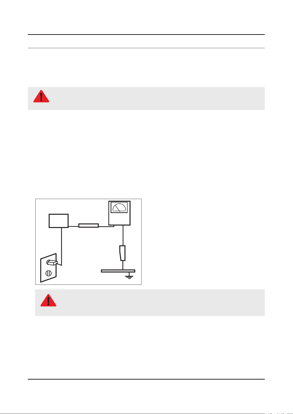
Leakage Current Hot Check:3.
Disconnect the AC power and DC power jack before servicing.
(READING SHOULD)
DEVICE
UNDER
TEST
ALSO TEST WITH
PLUG REVERSED
(USING AC ADAPTER
PLUG AS REQUIRED)
NOT BE ABOVE 0.5mA
2-WIRE CORD
TEST ALL
EXPOSED METAL
SURFACES
LEAKAGE
CURRENT
TESTER
EARTH
GROUND
Do not use an isolation transformer during this test.
Use a leakage current tester or a metering system that complies with American National Standards
WARNING
Institute (ANSI C101.1, Leakage Current for Appliances), and Underwriters Laboratories (UL
Publication UL1410, 59.7).
With the unit completely reassembled, plug the AC line cord directly into a 120V AC outlet. With the unit’s AC switch rst 4.
in the ON position and then OFF, measure the current between a known earth ground (metal water pipe, conduit, etc.)
and all exposed metal parts, including: metal cabinets, screwheads and control shafts.
The current measured should not exceed 0.5 milliamp.
Reverse the power-plug prongs in the AC outlet and repeat the test.
1-1
Page 17

1-2
1. Precautions
1-1-4. Product Safety Notices
Some electrical and mechanical parts have special safetyrelated characteristics which are often not evident from visual
inspection. The protection they give may not be obtained by replacing them with components rated for higher voltage,
wattage, etc. Parts that have special safety characteristics are identied by
replacement that does not have the same safety characteristics as the recommended replacement part might create
shock, re and/or other hazards. Product safety is under review continuously and new instructions are issued whenever
appropriate.
on schematics and parts lists. A substitute
Page 18

1-3
1. Precautions
1-2. Servicing Precautions
An electrolytic capacitor installed with the wrong polarity might explode.
WARNING
Before servicing units covered by this service manual, read and follow the Safety Precautions section of
CAUTION
NOTE
1-2-1. General Servicing Precautions
Always unplug the unit’s AC power cord from the AC power source and disconnect the DC Power Jack before 1.
attempting to: (a) remove or reinstall any component or assembly, (b) disconnect PCB plugs or connectors, (c) connect
a test component in parallel with an electrolytic capacitor.
Some components are raised above the printed circuit board for safety. An insulation tube or tape is sometimes used. 2.
The internal wiring is sometimes clamped to prevent contact with thermally hot components. Reinstall all such elements
to their original position.
After servicing, always check that the screws, components and wiring have been correctly reinstalled. Make sure that 3.
the area around the serviced part has not been damaged.
Check the insulation between the blades of the AC plug and accessible conductive parts (examples: metal panels, input 4.
terminals and earphone jacks).
Insulation Checking Procedure: Disconnect the power cord from the AC source and turn the power switch ON. Connect 5.
an insulation resistance meter (500 V) to theblades of the AC plug. The insulation resistance between each blade of the
AC plug and accessible conductive parts (see above) should be greater than 1 megohm.
Always connect a test instrument’s ground lead to the instrument chassis ground before connecting the positive lead; 6.
always remove the instrument’s ground lead last.
this manual.
If unforeseen circumstances create conict between the following servicing precautions and any of the
safety precautions, always follow the safety precautions.
Page 19

1-4
1. Precautions
1-3. Static Electricity Precautions
Some semiconductor (solid state) devices can be easily damaged by static electricity. Such components are commonly
called Electrostatically Sensitive Devices (ESD). Examples of typical ESD are integrated circuits and some eld-effect
transistors. The following techniques will reduce the incidence of component damage caused by static electricity.
Immediately before handling any semiconductor components or assemblies, drain the electrostatic charge from your 1.
body by touching a known earth ground. Alternatively, wear a discharging wrist-strap device. To avoid a shock hazard,
be sure to remove the wrist strap before applying power to the monitor.
After removing an ESD-equipped assembly, place it on a conductive surface such as aluminum foil to prevent 2.
accumulation of an electrostatic charge.
Do not use freon-propelled chemicals. These can generate electrical charges sufcient to damage ESDs.3.
Use only a grounded-tip soldering iron to solder or desolder ESDs.4.
Use only an anti-static solder removal device. Some solder removal devices not classied as “anti-static” can generate 5.
electrical charges sufcient to damage ESDs.
Do not remove a replacement ESD from its protective package until you are ready to install it. Most replacement ESDs 6.
are packaged with leads that are electrically shorted together by conductive foam, aluminum foil or other conductive
materials.
Immediately before removing the protective material from the leads of a replacement ESD, touch the protective material 7.
to the chassis or circuit assembly into which the device will be installed.
Be sure no power is applied to the chassis or circuit and observe all other safety precautions.
CAUTION
Minimize body motions when handling unpackaged replacement ESDs. Motions such as brushing clothes together, or 8.
lifting your foot from a carpeted oor can generate enough static electricity to damage an ESD.
Page 20

1-5
1. Precautions
1-4. Installation Precautions
For safety reasons, more than a people are required for carrying the product.1.
Keep the power cord away from any heat emitting devices, as a melted covering may cause re or electric shock.2.
Do not place the product in areas with poor ventilation such as a bookshelf or closet. The increased internal temperature 3.
may cause re.
Bend the external antenna cable when connecting it to the product. This is a measure to protect it from being exposed 4.
to moisture. Otherwise, it may cause a re or electric shock.
Make sure to turn the power off and unplug the power cord from the outlet before repositioning the product. Also check 5.
the antenna cable or the external connectors if they are fully unplugged. Damage to the cord may cause re or electric
shock.
Keep the antenna far away from any high-voltage cables and install it rmly. Contact with the highvoltage cable or the 6.
antenna falling over may cause re or electric shock.
When installing the product, leave enough space (0.4m) between the product and the wall for ventilation purposes. 7.
A rise in temperature within the product may cause re.
If an equipment is provided with a replaceable battery, and if replacement by an incorrect type could result in an 8.
explosion (for example, with some lithium batteries), the following applies:
Risk of explosion if battery is replaced by an incorrect type dispose of used batteries according to •
the instructions.
Do not dispose of batteries in a re.•
Do not short circuit, disassemble or overheat the batteries.•
CAUTION
Danger of explosion if battery is incorrectly replaced. Replace only with the same or equivalent •
type.
Do not be exposed to excessive heat such as sunshine, re or the like.•
Page 21
2. Product Specications
2-1. Product information
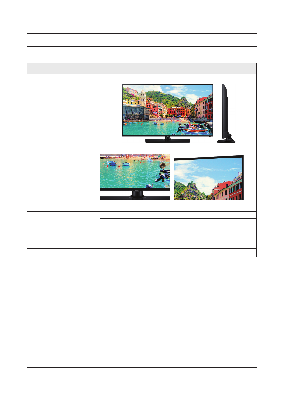
Model HG40ED590BB
2. Product specications
W
Front View
Detail View
Color Front Color : BLACK / Stand Color : BLACK
Dimensions
(W x D x H)
Weight 40"
Panel Type Black
40"
H
* W : Width H : High D : Depth
Set without Stand 905.2 x 525.4 x 91.1 mm
Set with Stand 905.2 x 562.3 x 196.4 mm
Set without Stand 7.3 kg
Set with Stand 9.6 kg
D
Internal Memory 4 GB
2-1
Page 22
2-2
2. Product specications
2-2. Product specication
2-2-1. Specications
Feature
Digital-TV, RF, 2-HDMI, 1-USB, LAN, WIFI•
PIP(in HDMI 1, 2 and Sub picture is available only in TV mode(DTV/ATV))•
Dolby MS10, DTS Premium Sound 5.1, DTS Studio Sound•
Specications
Model HG40ED590BB
Item Description
Screen Size 40 inches
LCD Panel FHD 60 Hz
Scanning Frequency Horizontal : 50 ~ 75 kHz
Vertical : 47 ~ 63 Hz
Display Colors 1.07B Dithered 10bit
Display Resolution 1920 x 1080
Input Signal Analog 0.7 Vp-p ± 5% positive at 75Ω, internally terminated
Input Sync Signal H/V Separate, TTL, P. or N.
Maximum Pixel Clock Rate 148.5 MHz
AC Power Voltage & Frequency AC 220 ~ 240V 50/60Hz
Environmental Considerations Operating Temperature : 50˚F ~ 104˚F (10˚C ~ 40˚C)
Operating Humidity : 10% ~ 80%, non-condensing
Storage Temperature : -4˚F ~ 113˚F (-20˚C ~ 45˚C)
Storage Humidity : 5% ~ 95%, non-condensing
Sound (Output) 20W (10W X 2)
Note : Smart Hub, Web Browser, USB HID, Hospitality Menu
Page 23
2-3
2. Product specications
2-2-2. Detailed Specications
NOTE
Design and specications are subject to change without prior notice.
Item HG40ED590BB
General Information
Display
Video
Product LED
Series 5
Inch 40
Resolution 1,920 x 1,080
Ultra Clear Panel No
Lvds Format JEIDA
HV Flip OFF
Picture Engine HyperReal Engine
Clear Motion Rate 100
Dynamic Contrast Ratio 100
Micro Dimming No
Precision Black (Local Dimming) No
Wide Color Enhancer (Plus) Yes
Auto Motion Plus 120Hz
Film Mode Yes
Brightness
Contrast Ratio
Detail Resolution 60 Hz
Response Time 8 ms
Viewing Angle (H/V) 178/178
350 cd/m
5000 : 1
2
Audio
SMART TV Functionality
Natural Mode Support No
Dolby MS10 / MS11 Dolby MS10
DTS Studio Sound / DNSe+ DTS Studio Sound
DTS Premium Sound / DTS Premium sound 5.1 DTS Premium sound 5.1
3D Sound No
Auto Volume Leveler Yes
Sound Customizer No
Speaker Type Down Firing + Full Range
Sound Output (RMS) 10W x 2
Woofer No
Sound Amp IC TI | TAS5747
Speaker 10W x 2
Woofer Speaker No
Smart Hub Yes
Page 24
2-4
2. Product specications
Item HG40ED590BB
SMART TV Functionality
Smart Interaction
Feature
Apps Yes
On TV No
Movies & TV Shows No
Samsung SMART View Yes
Recommendation Bar 2.0 No
Multi-Screen (Dual / Quad Screen) N/A
Samsung Sports Experience (SSE) N/A
Skype™ on Samsung TV Yes
Web Browser Yes
Social TV No
Multimedia Yes (Networked, Storage only)
Voice Interaction N/A
Voice Control N/A
Built In Camera N/A
Face Recognition No
Motion Control 3.0 No
Samsung 3D N/A
3D Converter N/A
Instant On N/A
N-KIT N/A
Quad Core+ N/A
Multi view N/A
History No
Multi Code Remote control Yes
Smart Evolution Ready
(Set Back / One connect)
Extended PVR Yes
Time Shift Yes
Digital Clean View Yes
ConnectShare™ (USB2.0) Movie
Analog Clean View No
RUI N/A
RVU No
WiFi Direct Yes
Wake On LAN Yes
N/A
Wireless LAN Built-in Yes
Wireless LAN Adaptor Support N/A
BT HID Built-in No
USB HID Support Yes
Page 25

2-5
2. Product specications
Item HG40ED590BB
Feature
OSD Language Local Languages
Hospitality Home Menu Yes
GUI Golden Bridge
MHL N/A
TV SoundConnect Yes
InstaPort S (HDMI quick switch) N/A
HDMI 1.4 3D Auto Setting N/A
HDMI 1.4 A/Return Ch. Support Yes
S/W EPG (Solution EPG) Yes
Teletext (TTX) Yes
Triple Protector No
Allshare - Screen Mirroring Yes
Anynet+ (HDMI-CEC) Yes
BD Wise Plus N/A
Auto Channel Search Yes
Auto Power Off Yes
Auto Volume Leveler Yes
Caption (Subtitle) Yes
Additional Feature
System
2 Tuner N/A
Clock&On/Off Timer No
Game Mode Yes
Picture-In-Picture Yes
Sleep Timer Yes
V-Chip No
Embeded POP No
Hospitality Plug & Play (Easy Setup) Yes
IP Video Closed Caption N/A
Self Diagnosis Yes
Software Upgrade Yes
HD Connection Guide Yes
Contact Samsung Yes
DTV Tuner DVB-T2CS2
Analog Tuner Yes
CI/ CI+ N/A
Broadcast System PAL MULTI, SECAM, NT4.4
ATV Sound System BK , DK , NICAM , MPEG1
DTV Video System PAL MULTI, SECAM, NT4.4
DTV Sound System Dolby
Page 26

2-6
2. Product specications
Item HG40ED590BB
System
Input & Output
Tuner Vendor & Model DVB-T2CS2
HDMI 2
Resolution
DVI Support Port HDMI IN 2
PC Max Resolution 1920 x 1080 | 60 Hz
USB 1
OS Linux
Component In (Y/Pb/Pr) No
Composite In (AV) No
Ethernet (LAN) 1
Headphone 1
Digital Audio Out (Optical) No
Audio Out (Mini Jack / LR) No
PC In (D-sub) 1
PC Audio In (Mini Jack) 1
DVI Audio In (Mini Jack) 1
RF In (Terrestrial/Cable input/Satellite Input) 1
1920 x 1080
Design
Eco
CI Slot YES
Coaxial No
EX-Link Yes (Common Use for RJ12)
PC Max Resolution 60 Hz
Design RHCM ToC
Bezel Type VNB
Slim Type 91.1 mm
Front Color Black
Light Effect (Deco) N/A
Stand Type Square
Swivel (Left/Right) No
Camera Type N/A
Eco Mark N/A
Eco Label Yes
Eco Sensor Yes
Page 27

2-7
2. Product specications
2-3. Accessories
NOTE
The items’ colors and shapes may vary depending on the model.•
Cables not included in the package contents can be purchased separately.•
The part code for some accessories may differ depending on your region.•
Product Code. No Product Code. No
Remote Control• AA59-00818A Quick Setup Guide• BN68-07242J
Batteries (AAA x 2)• 4301-000121 Safety Guide• BN68-03019A
Power Cord• 3903-000950
Image Product Code. No
Data Cable• BN39-00864A
Holder-Wire Stand• BN61-05491C
Page 28

2-8
2. Product specications
2-4. Viewing the Functions
2-4-1. Hotel Plug & Play
Hotel Plug & Play OSD
Initial Highlight: Interactive -
If you select the Standalone Only button, Standalone hotel mode is set by default and the “Standalone mode is set” OSD appears for 3 seconds.
TV enters into RF mode automatically after displaying “Standalone mode is set” OSD for 3 seconds. -
If you select the Interactive mode, the Interactive Setup Menu appears. Press the power off key to exit from the Interactive menu.
If you select the Standalone Plug & Play mode, the “Select Menu Language” OSD appears. -
Select Menu Language OSD
If you select Standalone from the “Select Hotel TV Mode” OSD, the “Select Menu Language” OSD appears. -
Initial Highlight : English -
Display time: OSD timeout and operation are the same as Samsung’s consumer TV models. -
If you press the Enter key, the “Select Country” OSD appears. -
Clock Mode OSD
Initial Highlight: Auto. -
Display time: 30 seconds. -
The Clock Set item OSD appears if you select Manual. -
If you press the Enter key after setting the clock, or while in Auto clock set, the Picture Mode OSD appears. -
Set daylight saving time OSD
Initial Highlight: Off -
If you press the Enter key, the Select the DST area OSD appears. -
Picture Mode OSD
Initial Highlight: Standard -
The TV displays the Picture Mode OSD where you can choose the Dynamic or a Standard Picture mode. -
After you select the picture mode, the TV displays the Standalone Setup Menu OSD. Press power off to exit. -
Auto Search Mode OSD
If you select the Skip option, the TV displays the Clock Mode OSD. -
If you press the Enter key, the TV auto searches for channels. -
The OSD Display time, which starts at the time that Auto Store is completed goes to the time Auto Sort starts, is 30 seconds.
Page 29

2-9
2. Product specications
2-4-2. Hospitality mode option
NOTE
Depending on Model and Region, some menu are NOT exist at TV set.
Hotel TV Function
Description
Category Item initial value
Hospitality Mode Hospitality Mode OFF Select the Hotel TV mode. (ON / OFF)
Set the default values, which will be applied when the
TV is turned on.
Power On Channel EN User Dened
Power On Channel 3 The TV will turn on to this particular channel.
Channel Type ATV
Power On
Power On Volume
EN
User Dened
Power On Volume 10 TV will turn on with this Volume Level.
Min Volume 0 Minimum Volume Level setting user can set.
Max Volume 100 Maximum Volume Level setting user can set.
Power on Source TV Select the Input source when TV is turned on initially.
Power On Option Last Option
Picture Menu Lock OFF Enable or disable the Picture Menu.
Menu OSD
Menu Display ON
Operation Panel Button Lock Unlock
Clock Local Time Manual
Music Mode Music Mode AV OFF
User Dened : Refers to the settings congured for •
Power On Channel, Channel Type.
Last Saved : Refers to the last saved settings.
•
Provides channel Type description for Power On
channel selected. i.e.
Selected channel analog or Digital & antenna
selection (Air or Cable).
Set the default volume values which will be applied
when the TV is turned on.
User Dened : Uses the settings congured for Power •
On Volume.
Last Saved : Uses the last saved settings.
•
Power On(AC Power On) Option
Standby : Stand-By Mode•
Power ON : Power On•
Last Option : Last Power State•
On : Main Menu display.•
Off : Main Menu No display.•
Front panel(Local key) operation on/off.
Unlock: Unlock All panel keys.•
Lock: Lock All panel keys.•
OnlyPower : Lock All panel keys except the Power panel •
key.
Menu/Source : Lock Menu and Source panel keys.
•
Select the method to update the clock data.
Manual: Use clock data from the DVB channel, or the •
manual clock setting when the TV is in stand-alone
mode.
TTX: manual clock setting (with updating from TTX data).
•
Use this for music output from an mp3/audio player
coming through an AV Input Source. When on, you
can hear sound from the player through the TV even
when there is no video signal. The TV’s backlight,
however, remains on. when adding a video signal, the
TV works normally.
Page 30

2. Product specications
Hotel TV Function
Description
Category Item initial value
Use this for music output from an mp3/audio player
coming through an PC Input Source. When on, you
Music Mode PC OFF
can hear sound from the player through the TV even
when there is no video signal. The TV’s backlight,
however, remains on. when adding a video signal, the
TV works normally.
Music Mode
Music Mode Comp. OFF
Use this for music output from an mp3/audio player
coming through an Component Input Source. When
on, you can hear sound from the player through the
TV even when there is no video signal. The TV’s
backlight, however, remains on. when adding a video
signal, the TV works normally.
Music Mode Backlight OFF
External Source Auto Source OFF
Use Backlight On/Off option in Music mode to save
energy.
OFF : Auto Source is Off.•
ON : When an external source is connected to the TV, •
the TV will auto-ident and switch the input source.
PC : Auto Ident PC Input only.
•
External Source Anynet+ Return Source Power On Src Set the return source after closing Anynet+.
This feature adjusts the brightness of the TV in order
to reduce power consumption.
Eco Solution Energy Saving Off
Clone TV to USB -
Clone USB to TV -
Cloning
Off: Turns off the energy saving function.•
Low: Sets the TV to low energy saving mode.•
Medium: Sets the TV to medium energy saving mode.•
High: Sets the TV to high energy saving mode.•
Clone the current TV option values to a USB memory
device.
Clone the saved TV option values in a USB memory
device to the TV.
When Setting Auto Initialize is set to On, and the
power is turned off and on or the Master Power is
turned off and on, the data is restored to the cloned
Setting Auto Initialize OFF
values.
If there is no cloned value, Setting Auto Initialize is set
to On, it will be ignored and the operation will be the
same as that when Setting Auto Initialize is set to Off
2-10
Page 31

4. Troubleshooting
4-1. Previous Check
Check list for initial operation
AC Power Cord connected to the TV and the wall receptacle.•
Standby Power/IR Indicator LED is turned On.•
If Power/IR Indicator is not on check 10p power cable is connected and for correct Standby Voltage from SMPS to •
Main. Also check Jog Function Cable.
Power turned On with Jog Function or Remote.•
Power on command from main Board to SMPS.•
Power/IR Indicator Flashes.•
Panel Back Lights are turned On.•
If no Backlights, unplug AC Power Cord, unplug 10 pin connector to SMPS, plug in AC Power Cord, Back light should •
come on. Check Main Board operation for error.
Power/IR Indicator goes off. •
Picture or banner is displayed.•
If nothing is displayed, check the LVDS cable. -
4. Troubleshooting
ASSY PCB MAIN
ASSY BOARD P-JOG SWITCH & IR
NETWORK-WIFI MODULE
SMPS
DC Output Connector
CNM803 : YEONHO (SMAW200-H10S5K)
PIN # Signal PIN # Signal
1 A13 2 OD_UD
3 A13 4 BLU_PWM
5 A13 6 PWR On/Off
7 A13 8 GND
9 GND 10 GND
DC VSS-LED PD BD
ASSY SPEAKER P (R/L)
CNL802 : YEONHO (SMAW200-H16S5K)
PIN # Signal PIN # Signal
1 Remove pin 2 3+
3 3- 4 Remove pin
5 Remove pin 6 2+
7 2- 8 Remove pin
9 Remove pin 10 1+
11 1- 12 Remove pin
13 Remove pin 14 Remove pin
15 IF2 16 IF1
4-1
Page 32

4-2
4. Troubleshooting
How to check inner pattern?
Move to Factory mode.1.
Power OFF INFO MENU MUTE Power On
Move to ‘Service Mode.’2.
Move to ‘Test pattern’.3.
Option
Control
Debug
SVC
ADC/WB
Advanced
Check inner patterns.4.
Test Pattern Pattern Sel
Page 33

4-2. How to Check Fault Symptom
4-3
4. Troubleshooting
4-2-1.No Power
The LEDs on The front panel do not work when connecting The power cord.•
Symptom
Major
checkpoints
The SMPS relay does not work when connecting The power cord.•
The units appears to be dead.•
The IP relay or the LEDs on the front panel does not work when connecting the power cord if the cables are
improperly connected or the Main Board or SMPS is not functioning. In this case, check the following:
Check the internal cable connection status inside the unit.•
Check the fuses of each part.•
Check the output voltage of SMPS.•
Replace the Main Board.•
Power cord on.
Yes
Check ‘DC A13V’ at BD233_7K_N75 ?
No
Cause : There did not supply the
power from SMPS.
Measure : Change 18P power cable
and SMPS.
Diagnostics
Yes
Set On.
Yes
1
2
Check ‘SW_POWER’ less than 0.5V
appear at Q202 ?
Yes
Check Power input of Main Ass’y ?
Q202 A3.3V appear at B13V (Q206) /
B5V (L201) ?
Yes
Check ‘Power of LVDS (13V)’ appear at
TP-PANEL_VCC?
13V (PANEL_VCC)
Yes
No
No
No
Cause : Main IC(X14H) did not control
the SW_Power.
Measure : Change the Main Assy.
Cause : There did not supply the
power from SMPS.
Measure : Change 18P power cable
and SMPS or Adaptor.
Measure : Change the Main Assy.
Change the LVDS cable
Caution Make sure to disconnect the power before working on the IP board.
No
Change the Panel.
Page 34

4-4
4. Troubleshooting
Location of Parts
Main Board_Front
2
12
CN203
1
2
Detail
Q202
2
Q206
L201
Page 35

4-2-2. No Video (HDMI 1, 2 - Digital Signal)
4-5
4. Troubleshooting
Symptom Audio is normal but no picture is displayed on the screen.•
Check the HDMI source.•
Major
checkpoints
Check the HDMI switch.•
This may happen when the LVDS cable connecting the Main Board and the Panel is •
disconnected.
Diagnostics
Power indicator LED is off.
Lamp(Backlight) on, no video ?
Yes
Check the HDMI source and check the
connection of HDMI cable ?
Yes
Check the signal at Input of Main Board ?
HDMI1 Clk•
Pin #10, #12 of CN501_H2
1
HDMI2 Clk •
Pin #10, #12 of CN502_H3
Check the LVDS clk signal at output of
2
TX2_CLK : ODD_TXCLK_DN/DP
TX4_CLK : EVEN_TXCLK_DN/DP
DATA Pin #7, #9, #4, #6, #1, #3 of
CN501_H2
DATA Pin #7, #9, #4, #6, #1, #3 of
CN502_H3
Yes
Main Board. (TX)
No
No
No
No
Check a set in the ‘Stand-by mode’.
Input the HDMI signal properly.
Check CN501~2.
Check HDMI cable.
Change the Main Ass’y.
or
Check IC1001(X14H).
Change the Main Ass’y.
Check IC1001(X14H).
Change the Main Ass’y.
Yes
Check the LVDS cable?
Replace the T CON / LCD panel?
Caution Make sure to disconnect the power before working on the IP Board.
No
Please, Contact tech support.
Page 36

4-6
4. Troubleshooting
Location of Parts
Main Board_Front
1
HDMI1 HDMI2
2
1
CN1402_FHD
Detail
CN501_H2 CN502_H3
2
Page 37

4-7
4. Troubleshooting
Waveforms
1 HDMI input (RX_Data, RX_Clk) 2 LVDS output
Page 38

4-8
4. Troubleshooting
4-2-3. No Video (Tuner_CVBS)
Symptom Audio is normal but no picture is displayed on the screen.•
Check the Tuner CVBS source.•
Major
checkpoints
Check the Tuner.•
This may happen when the LVDS cable connecting the Main Board and the Panel is •
disconnected.
Diagnostics
Power indicator LED is off.
Lamp(Backlight) on, no video ?
Yes
Check the RF source and check the
connection of RF cable.
Yes
Check the Power of Tuner ?
1
2
3
Pin #29 of Tuner : B3.3V_Tuner
Pin #4 of Tuner : B1.8V_Tuner
Yes
Check the CVBS data out of IC1001 ?
C807 : Tuner CVBS
Yes
Check the LVDS clk signal at output of
Main board. (TX)
TX2_CLK : ODD_TXCLK_DN/DP
TX4_CLK : EVEN_TXCLK_DN/DP
Yes
No
No
No
No
No
Check a set in the ‘Stand-by mode’.
Input the RF source properly.
Change the Main Ass’y.
Check IC1001(X14H).
Change the Main Ass’y.
Check IC1001(X14H).
Change the Main Ass’y.
Check the LVDS cable?
Replace the T CON / LCD panel?
Caution Make sure to disconnect the power before working on the IP Board.
No
Please, Contact tech support.
Page 39

4-9
4. Troubleshooting
Location of Parts
Main Board_Front
1
Tuner
PIN #29 : B3.3V
C730_FN/C731_FN
PIN #4 : B1.8V
(C710/ZC721)
2
2
IC1001
3
CN1402_FHD
C807
1
Detail
3
Page 40

4-10
4. Troubleshooting
Waveforms
1 CVBS OUT (Grey Bar) 3 LVDS output
Page 41

4-2-4. No Video
4-11
4. Troubleshooting
Symptom Audio is normal but no picture is displayed on the screen.•
Major
checkpoints
Diagnostics
Caution Make sure to disconnect the power before working on the IP Board.
Check the Video CVBS source.•
This may happen when the LVDS cable connecting the Main Board and the Panel is •
disconnected.
Power indicator LED is off.
Lamp(Backlight) on, no video ?
Yes
Check the video source and check the
connection of video cable?
Yes
Check the LVDS clk signal at output of
1
2
TX2_CLK : ODD_TXCLK_DN/DP
TX4_CLK : EVEN_TXCLK_DN/DP
Replace the T CON / LCD panel?
Main board. (TX)
Yes
Check the LVDS cable?
No
No
No
No
Check a set in the ‘Stand-by mode’.
Input the video source properly.
Check IC1001(X14H)
Change the Main Ass’y.
Please, Contact tech support.
Page 42

4-12
4. Troubleshooting
Location of Parts
Main Board_Front
1
IC1001
2
Detail
1 2
CN1402_FHD
Page 43

4-13
4. Troubleshooting
Waveforms
1 CVBS OUT (Grey Bar) 2 LVDS output
Page 44

4-14
4. Troubleshooting
4-2-5. No Sound (Speaker)
Symptom Video is normal but there is no sound.•
Major
checkpoints
Diagnostics
When the speaker connectors are disconnected or damaged.•
When the sound processing part of the Main Board is not functioning.•
Speaker defect.•
Check the source and check the
connection of sound cable ?
Yes
Check the signal at input of Main Board?
HDMI
Yes
Check the DATA between the Audio IC’s ?
1
2
Pin #45 of IC402 : B clk -
Pin #4 of IC402 : LR clk -
Pin #6, #7 of IC402 : I2C_SDA/SCL -
Yes
Check the Speaker sound data at ?
CN402
Yes
No
No
No
No
Input the sound source properly.
Check CN501, CN502.
Change the Main Ass’y.
Check IC402.
Change the Main Ass’y.
Change the Main Ass’y.
Replace speaker ?
Caution Make sure to disconnect the power before working on the IP Board.
No
Please, Contact Tech support.
Page 45

4-15
4. Troubleshooting
Location of Parts
Main Board_Front
1
1
2
SPEAKER
Detail
2
CN402
PIN #45 :B CLK
PIN #4 : LR CLK
PIN #6, 7 : I2C_SDA/SCL
Page 46

4-16
4. Troubleshooting
Waveforms
1 MCLK / LRCLK / PCM_I2C_DATA 1 MCLK / LRCLK / PCM_I2C_DATA
2 Speaker / Monitor OUT , SPDIF OUT 2 Speaker / Monitor OUT , SPDIF OUT
Page 47

4-3. Factory Mode Adjustments
4-17
4. Troubleshooting
4-3-1. Detail Factory Option
NOTE
If you replace the main board with new one, please change the factory option as well.
The options you must change are "Type".
HG40ED590BBXEN
Inches 40"
Vendor INX
PANEL
SMPS
MAIN
Byte Item
0 Factory Reset -
1 Type 40D6AF0S
2 Local set EU
3 SW Model HD590
4 BOM Model 590
5 Tuner AUTO
6 Ch table NONE
Code BN95-01875A
Spec. CY-HH040BGNV1V
Vendor SEM
Code BN44-00757A
Spec. L48G0B_ESM
ASSY CHASSIS BN91-15292F
ASSY PCB MAIN BN94-08837F
Page 48

4-18
4. Troubleshooting
4-3-2. Entering Factory Mode
To enter ‘Service Mode’ Press the remote -control keys in this sequence :
If you do not have Factory remote control•
Power OFF INFO MENU MUTE Power On
If you have Factory remote control•
INFO Factory
If you don’t have Factory remote control, can’t control some menus. (Expert, Advanced menu)•
Option
Control
Debug
SVC
ADC/WB
Advanced
T-MS14JDEUCB-1000.0
T-MS14JDEUSB-1000
BT Version : ****
Camera Version : ****
EDID FAIL
CALIB : AV / COMP / PC / HDMI /
Option : xxxx,EU,590,NONE
RFS : "X14xxxxx" KE/201x-xx-xx
KERNEL : xx.xxxx, /
DTP-DTVTD-xxxx-xxxx
TCON Version : ----
Model : HGxxED590
Wired MAC SUCCESS
Wireless MAC SUCCESS
WIFI : XXXXXX(x.x.xx_xxxx)
CIP SUCCESS
CO Nf/ W/ M/ D/ H2 PO AO / S/ N/ SC/
LYNK CRC : ----
Factory Data : xxx / EERC Version : xxx
SmartControl : ****
DTP-BP-HAL-xxxx
DTP-BP-MW-xxxx
DTP-BP-APP-xxxx
POP-FLA-14-FHD_SMART-xxx
Date of purchase : mm/dd/yyyy
MAIN SW Version
SUB SW Version
Page 49

4-3-3. Factory Data
4-19
4. Troubleshooting
Option
Factory Menu Name Data Range
Factory Reset
Type
Local Set
SW Model
BOM Model
TUNER
Ch Table
-
40D6AF0S
EU ED_MAL/ED_VIET/AD_SIN2/ED_INDIA/AD_
AU_NZ2/ED_THAI/ED_PHI/ED_INA
HD590
590
AUTO
NONE
MRT Option
Front Color U-S-C-55
Lvds Format JEIDA
Language_Arabic EU EU / ASIA
Region PANEURO
PnP Language ENG
WIFI REGION E
OTN Support ON
OTA Support General
MediaPlay DLNA ...
TTX ON
China HD OFF
NT Conversion OFF
Num of DTV DECODER 2
Num of AV 1
Num of COMP 0
Num of HDMI 3
Num of SCART 0
Num of USB Port 2
Num of USB3.0 0
Num of RVU 0
Num of Display 2
Num of IPTV 1
Num of RUI 0
PVR RECORD OFF
TOOLS Support 1913
LNA Support OFF
Page 50

4-20
4. Troubleshooting
Factory Menu Name Data Range
24Px4 Support OFF
BD Wise Support ON
Data Service Support OFF
PVR Support OFF
CI Support ON
LEDMotionPlus Support OFF
Natural Mode Support ON
Relax Mode Support OFF
HDMI/DVI SEL 3
Select LCD/PDP LCD
Wall Mount OFF
HV Flip HV Flip HV Flip / H Filp / OFF
Light Effect OFF
e-Pop Default ON
CAMERA Support OFF
NETWORK Support Int-Wi
EcoSensor Support ON
3D Support OFF
BT Support ON
BT ADDRESS Not support
HP LINE Headphone
Smart Control Support ON
Motion Recog OFF
Voice Recog ON
Virtual Remocon Color Black
Local Dimming Panel OFF
WiVendor QCA
Engineer Option
HORIZONTAL None
5 Way Function Key R BACK
Contents Bar OFF
Standby led on/off OFF
Recognition Support ON
IF AGC 0
D AGC 0
PH BW 0
FQ BW 0
Page 51

Factory Menu Name Data Range
4-21
4. Troubleshooting
PH RATE 0
PD EN 0
PEQ Inx 1
WF Scale
WF Type 0
Nu of Network Stream 1
DP V Size 0
Backend Device
BT_AUDIO_ON_OFF OFF
Cong_AV_PATH
ECO Standby OFF
Fast Logo Delay 0
Num of PANEL KEY 6
Panel Detail 0
Panel Init Time 500
Tcon Init Time 500
WRITE MAC Address
Control
Factory Menu Name Data Range
EDID
EDID ON/OFF OFF
EDID WRITE ALL …
EDID WRITE PC …
EDID WRITE HDMI …
EDID Ver …
EDID Port
Sub Option
RS-232 Jack UART Debug/UART
Serial Log On/Off ON
Watchdog OFF
FRC Monitoring OFF
Checksum 0x0000
Fast Boot in Production OFF
USB Serial OFF
Eeprom Reset
ECO IC TYPE MC8121
Page 52

4-22
4. Troubleshooting
Factory Menu Name Data Range
Info Link Server Type
Info Link Country None
TTX Group -
OPTION_SWU
OTN Server Type operating
OTN Test Server OFF
SWU Reset
SWU Duration OFF
SWU Fail Test OFF
OPTION_NUM
Num of ATV 1
Num of SVIDEO 0
Num of PC 1
Num of DVI 0
Num of OPTICAL Link 1
Num of MEDIA 1
Num of Tuner 1
Num of ISP 1
RF Remocon Support OFF
CDD mode -
DPMS Support OFF
Num of IPTV CIP 0
Num of CI 1
Num of DECODER 0
T-CON Device
BOARD CONTROL OFF
RM
Server Type Operating
RTS Mode OFF
PSA
FKP Download1 0
FKP Download2 0
LMK threshold 0
Low threshold 0
High threshold 0
CSB ON
CLB ON
Page 53

Factory Menu Name Data Range
4-23
4. Troubleshooting
EEPG Enable 0
Last screen OFF
App Resume ON
BP PMS Reset 1
FAnet Thread 2
User InstantOn Default Value OFF
ACM_MC OFF
Support Minibrowser OFF
HotkeyList HD690_NON_3D
Hotel Option
Hospitality Mode
SI Vendor
Power On
Power On Channel
Power On Volume
Min Volume
Max Volume
Power On Source
Power On Option
Channel
Channel Setup
Channel Editor
Mixed Channel Map
Dynamic SI
Channel Rescan Message
Pan Euro MHEG
Mychannel
Subtile Auto On
Menu OSD
Picture Menu Lock
Menu Display
Panel Button Lock
Home Menu Display
Home Menu Editor
Home Menu Auto Start
Clock
Clock Type
Page 54

4-24
4. Troubleshooting
Factory Menu Name Data Range
Local Time
Music Mode
Music Mode AV
Music Mode PC
Music Mode Backlight
Remote Jack Pack
Priority AV
Priority PC
Priority HDMI
AV Option
HDMI Option
External Source
USB Pop-up Screen
External Source Banner
Auto Source
Anynet+ Return Source
Bathroom Speaker
Sub Amp Mode
Sub Amp Volume
Eco Solution
Energy Saving
Logo/Message
Welcome Meassage
Edit Welcome Message
Hospitality Logo
Hospitality Logo DL
Logo Display Time
Cloning
Clone TV to USB
Clone USB to TV
Setting Auto Initialize
REACH Server
REACH 3.0
REACH 2.0
REACH Channel
Group ID
Ticker
Page 55

Factory Menu Name Data Range
4-25
4. Troubleshooting
REACH Update Time
REACH Update Immediate
Room Number
REACH 2.0 TV Sound
REACH 2.0 Server Version
Network
Network Setup
SmartHub Model Setting
SmartHub Setting
SYSTEM
Self Diagnosis for TV
Self Diagnosis for HTV
SW Update
Service Pattern
Sound Bar Out
Contact Samsung
TV Reset
Shop Option
Shop Mode
Exhibition Mode OFF
3D CUBE OFF
Asia Option
Unbalance OFF
AF Level adjust 3
TX Power Level 0
Mono Last Memory OFF
H Shaking OFF
SOUND
Carrier_Mute OFF
High Devi OFF
Speaker Delay Normal 0x0Ah
SPDIF PCM Gain -9 dB
FM M Prescale 0x30h
FM Prescale 0x44h
AM Prescale 0x32h
NICAM Prescale 0x48h
BTSC Mono Prescale 0x19h
Page 56

4-26
4. Troubleshooting
Factory Menu Name Data Range
BTSC Stereo Prescale 0x2Fh
BTSC SAP Prescale 0x2Bh
A2 Ident High THLD 36
A2 Ident Low THLD 9
Pilot Level High Thld 0x28h
Pilot Level Low THLD 0x10h
Carrier2 Amp High ThLD 4
Carrier2 Amp Low THLD 3
Carrier2 SNR High THR 16
Carrier2 SNR Low THR 80
Sig Error On 35
Sig Error Off 41
Amp Model NTP7414
Amp Volume 0xc5h
Amp Scale 0x9ah
Amp Check Sum
Woofer Type 0
Woofer Volume 0xcbh
Woofer Scale 0x8ah
Woofer Check sum NONE
Woofer Local Check Sum 0
Speaker EQ ON
PEQ Test Ready
Local Speaker EQ 0
Local EQ Checksum 0
SRS Tuning Parm 0
Subwoofer Support 0
India Sound OFF
AudioDock BT Delay 50
Wall Filter Type 0
Bottom CheckSum 0
Bottom Local CheckSum 0
Lipsync Inx 0
Lipsync CheckSum OK:0x920A
Lipsync USB Test Ready
Lipsync BT CheckSum OK:0x4128
Debug
Page 57

Factory Menu Name Data Range
4-27
4. Troubleshooting
Spread Spectrum
LVDS Spread ON
DDR Spread 1.0% Spectrum
Period 30K
Amplitude 1.0
HD SSC ON/Off ON
HD SSC Value 1
LVDS SSC ON/Off ON
LVDS SSC Value 1
DDR SSC ON/Off ON
DDR SSC Value 1
FRC LVDS SSC ON/OFF OFF
FRC LVDS SSC MRR 10
FRC LVDS SSC MFR 1
FRC LVDS SSC Period 0
FRC LVDS SSC Modulation 1
FRC DDR SSC ON/OFF ON
FRC DDR SSC MRR 15
FRC DDR SSC MFR 1
FRC DDR SSC Period 1
FRC DDR SSC Modulation 1
DDR Margin
A CTRL_OFFSET_0_3 0x0
A CTRL_OFFSET_D 0x0
B CTRL_OFFSET_0_3 0x0
B CTRL_OFFSET_D 0x0
MICOM POWER OFF
RF Mute Time
CI+1.3
OFF
6ms
ON
FRC
FRC FDISPLAY ON/OFF 0
3D FDISPLAY ON/OFF OFF
PC Mode ON/OFF OFF
Home Panel FRC OFF
DDR Test 0
Tuner Margin
MPEG Margin
10
100
Page 58

4-28
4. Troubleshooting
Factory Menu Name Data Range
H.264 Margin
CAM Wait Time
TS Clock deldy
TCON_TEMP READ
TEMP LAST
DCC VERSION
DCC CHK SEL
DCC CHECK LOCAL
DCC CHECK TOTAL
MulitACC Checksum
IIC Bus stop
Tuner Status
DVB
SNR
BER
Signal Strength
Bandwidth
100
0
48.50
48.54
0x4AA9
0
0x0
0x0
0
OFF
Frequency
LNA Status
FFT
Modulation
Code Rate
GI
Hier Modulation
Frequency offset
Timing offset
AGC
UCB
PLL Type
DEMOD Type
TPS Lock
RS Lock
SSI
SQI
Firmware Version
ISDB-T
FFT Size_1
Page 59

Factory Menu Name Data Range
4-29
4. Troubleshooting
Guard Interval_1
Freq. Offset_1
SNR_1
IF AGC_1
TMCC Lock_1
TS Packer_1
Master Lock_1
A_Modulation_1
A_Code Rate_1
A_Timer InterLeave_1
A_Segments Num_1
A_BER_1
B_Modulation_1
B_Code Rate_1
B_Timer InterLeave_1
B_Segments Num_1
B_BER_1
C_Modulation_1
C_Code Rate_1
C_Timer InterLeave_1
C_Segments Num_1
C_BER_1
Cert option
RM_BIST_DTV
RM_BIST_ATV
Voice Debug
Stress Mode
SHOW / HIDE
0
0
OFF
OFF
SVC
Factory Menu Name Data Range
Self Diagnosis
Loop Back
LAN Test
AV Audio Test
DVIN Audio Test
CVBS Test
COMP Test
Page 60

4-30
4. Troubleshooting
Factory Menu Name Data Range
USB HUB Test
HDMI Test
SCART Audio Test
SCART CVBS Test
SCART RGB Test
PC Audio Test
PC Self Test
CPU
DDR
FLASH
EEPROM
HDMI Switch IC
WIFI
LVDS
T-CON/FRC
PCB Test
MOIP
App Self Test
Device self Test
Voltage
EcoSensor
BT
EXT Sound Inspection
Woofer Sound Inspection NONE
ATV CH Inspection
DTV CH Inspection
Satellite CH Inspection
Aging Line Test
Info
LOG(View Log)
Select Log Type
Log View
Delete Log
Debug Log Down
RM log transmission
ER Count
WD Count
Page 61

Factory Menu Name Data Range
4-31
4. Troubleshooting
Power Fail Count
AR Count
WIFI ER Count
WIFI Detachment count
BT ER Count
BT No Detection Count
BT Detachment Count
BT MGT Open Fail Count
BT MGT Disconnect Count
Camera ER Count
FRC3D ER Count
Panel Display Time
Factory Entry Number
Factory Execution History
Factory Reset History
Upgrade
T-CON Usb Download Failute
T-CON CheckSum N/A
Logic Usb D/L …
SUBMICOM UPGRADE Ready
BT UPGRADE
BT FREEPAIRING ON
Function Upgrade Failute
FRC3D FW Upgrade
FRC3D LD UPGRADE
Camera Upgrade
Mic Upgrade
CPLD USB Download
JP MICOM UPGRADE Failute
DP MICOM UPGRADE Failute
Jump Upgrade Failute
IR Blaster Upgrade Failure
IR Blaster delay time
CPLD Download
LDCProleUpgrade
Pic Data USB Update
Audio Data USB Update
Page 62

4-32
4. Troubleshooting
Factory Menu Name Data Range
Eco Data USB Update
SC ADK Upgrade
SC MBR Upgrade
Reset
Smart Hub Reset
EEPROM Rst
Factory Rst
OPTION_HDMI
DVB CI
Test Pattern
Pattern Sel OFF
Logic Pattern Sel …
Logic Level Sel …
FRC Pre Test Pattern 0
FRC Post Test Pattern 0
SOC TCON Test Pattern 0
SOC TCON Pattern Level 255
SOC TCON FRC Pattern 0
HDMI WB Pattern OFF
HDMI Pattern Sel 0
Parma Pre Test Pattern 0
Parma Post Test Pattern 0
FRC OSD Pre Pattern
FRC OSD Post Pattern
Other Setting
SVC Panel
ADC/WB
Factory Menu Name Data Range
ADC
AV Calibration Success
Comp Calibraion Success
PC Calibration Success
HDMI Calibration Success
ADC Result
1st_Y_GH 258
1st_Y_GL 128
Page 63

Factory Menu Name Data Range
4-33
4. Troubleshooting
1st_Cb_BH …
1st_Cb_BL …
1st_Cr_RH …
1st_Cr_RL …
2nd_R_L 132
2nd_G_L 132
2nd_B_L 132
2nd_R_H 70
2nd_G_H 70
2nd_B_H 70
White Balance
R-Offset 128
G-Offset 128
B-Offset 128
R-Gain 128
G-Gain 128
B-Gain 128
WB_W2_R_Offset 128
WB_W2_B_Offset 128
WB_W2_R_Gain 158
WB_W2_B_Gain 61
WB_N_R_Offset 128
WB_N_B_Offset 128
WB_N_R_Gain 147
WB_N_B_Gain 106
MGA
MGA On/Off OFF
R1_Gain …
B1_Gain …
G1_Gain …
R2_Gain …
B2_Gain …
G2_Gain …
R3_Gain …
B3_Gain …
G3_Gain …
R4_Gain …
Page 64

4-34
4. Troubleshooting
Factory Menu Name Data Range
B4_Gain …
G4_Gain …
R5_Gain …
B5_Gain …
G5_Gain …
R6_Gain …
B6_Gain …
G6_Gain …
R7_Gain …
B7_Gain …
G7_Gain …
R8_Gain …
B8_Gain …
G8_Gain …
R9_Gain …
B9_Gain …
G9_Gain …
R10_Gain …
B10_Gain …
G10_Gain …
Page 65

4-4. White Balance
4-35
4. Troubleshooting
4-4-1. Calibration
Into the Factory Mode.1.
Select 2. ADC/WB menu.
Select 3. ADC menu.
Option
Control
Debug
SVC
ADC/WB
Advanced
ADC
ADC Result
White Balance
MGA
AV Calibration
Comp Calibration
PC Calibration
HDMI Calibration
4-4-2. Service Adjustment
You must perform Calibration in the Lattice Pattern before adjusting the White Balance.
Color Calibration
AdjustSpecication•
Source Setting Mode Pattern Use Equipment
HDMI 1280 x 720@60 Hz Pattern #24 (Chess Pattern) CA210 & Master MSPG925 Generator
(Chess Pattern)
Use other equipment only after comparing the result with that of the Master equipment. -
Input mode Calibration Pattern
CVBS IN (Model_#1) Perform in NTSC B&W Pattern #24 Lattice
Component IN (Model_#6) Perform in 720p B&W Pattern #24 Lattice
HDMI IN Perform in 720p B&W Pattern #24 Lattice
Page 66

4-36
4. Troubleshooting
Method of Color Calibration (PC)
Apply the VESA XGA Lattice (N0. 21) pattern signal to the PC IN port.1.
Press the Source key to switch to “PC” mode.2.
Enter Service mode.3.
Select the “ADC” menu.4.
Select the “PC Calibration” menu.5.
In“PCCalibrationOff”status,pressthe“►”keytoperformCalibration.6.
When Calibration is complete, it returns to the high-level menu.7.
You can see the change of the “PC Calibration” status from Failure to Success.8.
Method of Color Calibration (HDMI)
Apply the 720p Lattice (N0. 6) pattern signal to the HDMI1/DVI IN port.1.
Press the Source key to switch to “HDMI1” mode.2.
Enter Service mode.3.
Select the “ADC” menu.4.
Select the “HDMI Calibration” menu.5.
In“HDMICalibrationOff”status,pressthe“►”keytoperformCalibration.6.
When Calibration is complete, it returns to the high-level menu.7.
You can see the change of the “HDMI Calibration” status from Failure to Success.8.
Page 67

4-4-3. Adjustment
4-37
4. Troubleshooting
Into the Factory Mode.1.
Select 2. ADC/WB menu.
Select 3. White Balance menu.
Option
Control
Debug
SVC
ADC/WB
Advanced
ADC
ADC Result
White Balance
MGA
(Low Light)
Sub Brightness
R offset
G offset
B offset
(Hight Light)
Sub Contrast
R gain
G gain
B gain
Page 68

4-38
4. Troubleshooting
4-5. RS-232C
RS232C Control•
Port : COM#(Serial) -
Bit rate : 115200 -
Data Bit : 8 bit -
Parity : None -
Stop Bits : 1 -
Flow Control : None -
Description of RS232C•
Pin# Name Full Name Pin# Name Full Name Pin# Name Full Name
CD Carrier Detect
1
RxD Received Data
2
TxD Transmitted Data
3
DTR Data Terminal Ready
4
GND Signal Ground
5
DSR Data Set Ready
6
RTS Request To Send
7
CTS Clear To Send
8
RI Ring Indicator
9
Page 69

4-6. Software Upgrade
4-39
4. Troubleshooting
How to Upgrade SW and Micom
InsertaUSBdrivecontainingthermwareupgradedownloadedfromsamsung.comintotheSet.Pleasebe careful to not disconnect the power or remove the USB drive while upgrades are being applied.
Thesetwillturnoffandturnonautomaticallyaftercompletingthermwareupgrade.Pleasecheckthermware version after the upgrades are complete (the new version will have a higher number than the old version).
When software is upgraded, video and audio settings you have made will return to their default (factory) settings. We recommend you write down your settings so that you can easily reset them after the upgrade.
4-6-1. Main SW Upgrade
YouneedUSB,includingupdatele.1.
http://displaysolutions.samsung.com/resources/downloadCenter?method=list - save "T-MS14JAKUCB"
leinUSB.
Store the SW program named "2. T-MS14JAKUCB" in a USB memory stick.
Main SW
Connect the USB memory stick.3.
USB memory stick
Click the 4. MENU button on the remote control.
You can use OSD menu. -
Select 5. Support menu.
Locate the menu cursor - Software Upgrade menu.
Page 70

4-40
4. Troubleshooting
Locate the menu cursor 6. Update now menu.
Click the 7. YES button.
Page 71

4-41
4. Troubleshooting
4-6-2. SUBMICOM Upgrade
You can upgrade SUBMICOM in factory mode without DDC program. But it take long time about 5 minutes.
Store the SW program named 1. SubMicomEU.bin in a USB memory stick.
SubMicom
Connect the USB memory stick.2.
USB memory stick
Access the factory mode. Select the 3. SVC menu.
Option
Control
Debug
SVC
ADC/WB
Advanced
Select the 4. UPGRADE menu.
Self Diagnosis
Info
Upgrade
Reset
OPTION_HDMI
DVB CI
TestPattern
Other Setting
SVC Panel
Page 72

4. Troubleshooting
Locate the cursor 5. SUBMICOM upgrade menu.
T-CON Usb Download Failure IR Blaster Upgrade Failure
T-CON CheckSum N/A IR Blaster delay time 50
Logic Usb D/L -
SUBMICOM UPGRADE off LDC Prole Upgrade 0
BT UPGRADE Pic Data USB Upgrade 0
BT FREEPAIRING ON Audio Data USB Upgrade 0
Fuction Upgrade Failure Eco Data USB Upgrade 0
FRC3D FW Upgrade SC ADK Upgrade Failure
FRC3D LD Upgrade 0000 SC MBR Upgrade Failure
Camera Upgrade
Mic Upgrade ON
CPLD USB Download
JP MICOM UPGRADE Failure
DP MICOM UPGRADE Failure
Jump Upgrade Failure
CPLD Download
Click the 6. Enter button.
Click the 7. Right(►)buttonontheremotecontrol.
Wait for upgrade complete about 5 minutes. -
SUBMICOM UPGRADE Ready
SUBMICOM UPGRADE Upgrading...
Check the Micom version.8.
4-42
Page 73

5. Wiring Diagram
Main Board
Speaker
SMPS Board
CNL802
CN203
CN1201
CN402
CN1402_FHD
CNM803
T- CON+Source Board
Speaker
WiFi
Function
5-1. Wiring Diagram
5. Wiring Diagram
5-1
Page 74

5-2
5. Wiring Diagram
5-2. Connector
Main Board
CN502_H3
14
CN501_H2
13
CN1402_LAN
12
CN203
1
2
TU703_FN
(TUNER)
CN1402_FHD
CN402
3
CN701_PC
4
CN702_PC
5
CN401
11
CN1801
10
CN1802
9
CN202
8
CN1501_U1
7
CN1601_CI
6
Main Board Pin Map
CN203 (to Power board)
1
1 GND 5 A13V_PW 9 A13V_PW
2 GND 6 SW_POWER_OUT 10 OVD_LEVEL
3 A13V_PW 7 A13V_PW
4 GND 8 SW_INVERTER
CN1201
Page 75

5-3
5. Wiring Diagram
CN1402_FHD
2
1 NC 27 EVEN_TX0-_LVDS
2 GND 28 GND
3 NC 29 ODD_TX4+_LVDS
4 NC 30 ODD_TX4-_LVDS
5 NC 31 ODD_TX3+_LVDS
6 NC 32 ODD_TX3-_LVDS
7 GND 33 GND
8 TCON_SDA 34 ODD_TXCLK+_LVDS
9 PANEL_I2C_EN 35 ODD_TXCLK-_LVDS
10 NC 36 GND
11 NC 37 ODD_TX2+_LVDS
12 TCON_SCL 38 ODD_TX2-_LVDS
13 GND 39 ODD_TX1+_LVDS
14 EVEN_TX4+_LVDS 40 ODD_TX1-_LVDS
15 EVEN_TX4-_LVDS 41 ODD_TX0+_LVDS
16 EVEN_TX3+_LVDS 42 ODD_TX0-_LVDS
17 EVEN_TX3-_LVDS 43 GND
18 GND 44 GND
19 EVEN_TXCLK+_LVDS 45 GND
20 EVEN_TXCLK-_LVDS 46 NC
21 GND 47 PANEL_13V_PW
22 EVEN_TX2+_LVDS 48 PANEL_13V_PW
23 EVEN_TX2-_LVDS 49 PANEL_13V_PW
24 EVEN_TX1+_LVDS 50 PANEL_13V_PW
25 EVEN_TX1-_LVDS 51 PANEL_13V_PW
26 EVEN_TX0+_LVDS
CN402 (to SPEAKER)
3
1 R+ 3 L-
2 R- 4 L+
CN702_PC
5
1 GND 5 TEST_SR
2 PC_DVI_SL_IN 6 NC
3 PC_DVI_SR_IN 7 GND
4 TEST_SL
CN1201_FUN(to Function/IR)
6
1 IR 14 A5V
2 GND 15 LED_STB
3 GND 16 BT_WAKE
4 FRAME_SYNC_IN 17 GND
5 A3.3V 18 POWER_DET
6 BT_SYNC 19 NC
7 MSCL 20 BT_RESET
8 GND 21 GND
9 MSDA 22 WIFI_DP
10 USB_BT_DP 23 WIFI_DM
11 KEY_INPUT1 24 B5V_DC_PW
12 USB_BT_DM 25 WIFI_WOL
13 KEY_INPUT2 26 WIFI_RESET
CN1501_U1(USB1)
7
1 B5V_USB1_PW 3 USB1_DP
2 USB1_DM 4 GND
CN1202
8
1 GND 3 DSDA
2 DSCL 4 GND
CN1802
9
1 GND 5 FANET_TX
2 FANET_RX 6 GND
3 FANET_TX 7 NC
4 FANET_TX
CN701_PC
4
1 PC_R 9 PC_5V
2 PC_G 10 IDENT_PC
3 PC_B 11 NC
4 NC 12 PC_SDA
5 GND 13 PC_HSYNC
6 GND 14 PC_VSYNC
7 PC_G 15 PC_SCL
8 GND
CN1801
10
1 IR (#2 OPTION) 4
2 1R (#1 OPTION) 5 TDB_SUB_HOTEL
3 RX_RJ12_RS232 6 TX_RJ12_RS232
MTI_CLK_HT
RDB_SUB_HOTEL
Page 76

5-4
5. Wiring Diagram
C401
11
1 GND 8 GND
2 HP_AUD_SL_OUT 9 IDENT_HP
3 HP_AUD_SR_OUT 10 IDENT_HP
4 TEST_SL 11 NC
5 TEST_SR 12 NC
6 IDENT_HP 13 NC
7 GND 14 GND
CN1402 (to LAN)
12
1 LAN_TXD+ 5 GND
2 GND 6 LAN_RXD-
3 LAN_TXD- 7 NC
4 LAN_RXD+ 8 GND
CN501_H2 (to HDMI1)
13
1 HDMI1_RX2+ 11 GND
2 GND 12 HDMI1_RXCLK-
3 HDMI1_RX2- 13 CEC
4 HDMI1_RX1+ 14 NC
5 GND 15 HDMI1_SCL_DDC
6 HDMI1_RX1- 16 HDMI1_SDA_DDC
7 HDMI1_RX0+ 17 GND
8 GND 18 HDMI1_5V
9 HDMI1_RX0- 19 HDMI1_HOT_PLUG
10 HDMI1_RXCLK+
CN502_H3 (to HDMI2)
14
1 HDMI1_RX2+ 11 GND
2 GND 12 HDMI1_RXCLK-
3 HDMI1_RX2- 13 CEC
4 HDMI1_RX1+ 14 NC
5 GND 15 HDMI1_SCL_DDC
6 HDMI1_RX1- 16 HDMI1_SDA_DDC
7 HDMI1_RX0+ 17 GND
8 GND 18 HDMI1_5V
9 HDMI1_RX0- 19 HDMI1_HOT_PLUG
10 HDMI1_RXCLK+
Page 77

5-5
5. Wiring Diagram
5-3. Connector Functions
Connector Function
CN203 ↔ CNM803 Supply main power and dimming signal from IP Board to Main Board.
CNL802 ↔ PANEL Backlight power supply of panels.
CN1402_FHD ↔ T-CON The LVDS signal transfered from Main Board to Panel.
Page 78

5. Wiring Diagram
5-4. Cables
USE
Code 40" BN96-33236Q BN39-01885S BN39-01929N
Photo
NOTE
The code number of cable (Lead-connector) can be changed, see "Exploded Views and Parts List".
Main-T CON (51P) Main-SMPS Main-FUNCTION
ASSY CABLE P-FFC LEAD CONNECTOR LEAD CONNECTOR-FUNCTION
5-6
 Loading...