


SAMSUNG MEDISON
DIAGNOSTIC ULTRASOUND SYSTEM
H60
User Manual
Volume 1


SAMSUNG MEDISON
DIAGNOSTIC ULTRASOUND SYSTEM
Version 2.00
H60
User Manual
English


PROPRIETRAY INFORMATION AND SOFTWARE LICENSE
The Customer shall keep confidential all proprietary information furnished or disclosed to the Customer
by Samsung Medison, unless such information has become part of the public domain through no fault of
the Customer. The Customer shall not use such proprietary information, without the prior written consent
of Samsung Medison, for any purpose other than the maintenance, repair or operation of the goods.
Samsung Medison’s systems contain Samsung Medison’s proprietary software in machine-readable
form. Samsung Medison retains all its rights, title and interest in the software except that purchase of this
product includes a license to use the machine-readable software contained in it. The Customer shall not
copy, trace, disassemble or modify the software. Transfer of this product by the Customer shall constitute
a transfer of this license that shall not be otherwise transferable. Upon cancellation or termination of this
contract or return of the goods for reasons other than repair or modification, the Customer shall return to
Samsung Medison all such proprietary information.


Safety Requirements
Classifications:
X
Type of protection against electrical shock: Class I
X
Degree of protection against electrical shock (Patient connection): Type BF or CF Applied Part
X
Degree of protection against harmful ingress of water: Ordinary equipment
X
Degree of safety of application in the presence of a flammable anesthetic material with air or
with oxygen or nitrous oxide: Equipment not suitable for use in the presence of a flammable
anesthetic mixture with air or with oxygen or nitrous oxide.
X
Mode of operation: Continuous operation
Electromechanical safety standards met:
X Medical Electrical Equipment, Part 1: General Requirements for Basic Safety and Essential
Performance [IEC 60601-1:2005/A1:2012]
X Medical Electrical Equipment, Part 1-2: General Requirements for Basic Safety and Essential
Performance- Collateral Standard: Electromagnetic Compatibility - Requirements and Tests
[IEC 60601-1-2:2007]
X Medical Electrical Equipment, Part 1-6: General Requirements for Basic Safety and Essential
Performance- Collateral Standard: Usability [IEC 60601-1-6:2010]
X Medical Electrical Equipment, Part 2-37: Particular Requirements for the Basic Safety and Essential
Performance of Ultrasonic Medical Diagnostic and Monitoring Equipment [IEC 60601-2-37:2007]
X Medical Electrical Equipment, Part 1: General Requirements for Safety [IEC 60601-1:1988 with
A1:1991 and A2:1995]
X Medical Electrical Equipment, Part 1-1: General Requirements for Safety - Collateral Standard: safety
Requirement for Medical Electrical Systems [IEC 60601-1-1:2000]
X Medical Electrical Equipment, Part 1-2: General Requirements for Safety - Collateral Standard:
Electromagnetic Compatibility - Requirements and Test [IEC 60601-1-2:2001, A1:2004]
X Medical Electrical Equipment, Part 1-4 : General Requirements for Safety - Collateral Standard:
Programmable Electrical Medical Systems [IEC 60601-1-4:1996, A1:1999]

X Medical Electrical Equipment, Part 2-37: Particular Requirements for Safety - Ultrasonic Medical
Diagnostic and Monitoring Equipment [IEC 60601-2-37:2001 with A1:2004, A2:2005]
X Medical Devices – Application of Risk Management to Medical Devices [ISO 14971:2007]
X Medical Electrical Equipment, Part 1: General Requirements for Safety [UL 60601-1:2003]
X Medical Electrical Equipment - Part 1: General Requirements for Safety [CAN/CSA C22.2 No. 601.1-
M90:1990, with R2003, with R2005]
X Biological Evaluation of Medical Devices, Part 1:Evaluation and Testing within a risk management
process [ISO 10993-1:2009]
X Standard Means for the Reporting of the Acoustic Output of Medical Diagnostic Ultrasonic Equipment
[IEC 61157:2007]
Declarations
CSA mark with the indicators “C” and “US” means that the product is certified for
both the U.S. and Canadian markets, to the applicable U.S. and Canadian standards.
This is the manufacturer’s declaration of product compliance with applicable EEC
directive(s) and the European notified body.
This is the manufacturer’s declaration of product compliance with applicable EEC
directive(s).
This is the GMP symbol that shows that the product complies with the Korean Good
Manufacturing Practice quality regulation system.

Precautions For Use
You should be familiar with all of these areas before attempting to use this manual or your ultrasound
system.
Please keep this user guide close to the product as a reference when using the system.
For safe use of this product, you should read ‘Chapter 1. Safety’ and ‘Chapter 4. Maintenance’ in this
manual, prior to starting to use this system.
This manual does not include diagnosis results or opinions. Also, check the measurement reference for
each application’s result measurement before making the final diagnosis.
This product is an ultrasound scanner and cannot be used from a user’s PC. We are not responsible for
errors that occur when the system software is run on a user’s PC.
Only medical doctors or persons supervised by medical doctors should use this system. Persons who are
not qualified must not operate this product.
The manufacturer is not responsible for any damage to this product caused by carelessness and/or
neglect by the user.
Please note that orders are based on the individually agreed specifications and may not contain all
features listed in the user manual.
It might be possible that some features, options or probes are NOT available in some countries.
All references to standards / regulations and their revisions are valid for the time of publication of the
user manual.
The figures in the user manual for illustrational purposes only and may be different from what you see
on the screen or device.
Information contained in this operating manual is subject to change without prior notice.
Products that are not manufactured by Samsung Medison are marked with the trademark of their
respective copyright holders.
The headings below describe vitally important precautions necessary to prevent hazards.

DANGER: Disregarding this instruction may result in death, serious injury, or other dangerous
situations.
WARNING: Follow these instructions to prevent a serious accident or damage to property.
CAUTION: Follow these instructions to prevent a minor accident or damage to property.
NOTE: The accompanying information covers an installation, operation, or maintenance
procedure that requires careful attention from the user, but has little chance of leading directly to
a dangerous situation.

Revision History
The revision history of this manual is as follows.
VERSION DAT E NOTE
v2.00.00-01 2014.08.27
Initial Release
Product Upgrade and Manual Update
Upgrades to this product can include upgrades to its hardware or software components. Revised
versions of this manual will be published to reflect any upgrades to the product.
Please make sure that your user manual is appropriate for your product version. If not, please contact
Samsung Medison's Customer Service Department.
If You Need Assistance
If you need any assistance with the equipment, or the service manual, please contact Samsung Medison‘s
Customer Service Department or one of their worldwide customer service representatives immediately.


Table of Contents
Table of Contents – Volume 1
Chapter 1 Safety
Indication for Use ....................................................................................................................... 1-3
Contraindications ..............................................................................................................................................................1-3
Safety Information ..................................................................................................................... 1-4
Safety Symbols .................................................................................................................................................................... 1-4
Symbols ................................................................................................................................................................................. 1-5
Labels ...................................................................................................................................................................................... 1-6
Electrical Safety .......................................................................................................................... 1-7
Prevention of Electric Shocks ........................................................................................................................................ 1-7
ECG-Related Information ................................................................................................................................................ 1-8
ESD ........................................................................................................................................................................................... 1-9
EMI ........................................................................................................................................................................................... 1-9
EMC ......................................................................................................................................................................................1-10
Mechanical Safety .................................................................................................................... 1-17
Moving the Equipment ..................................................................................................................................................1-17
Precautions for Use ..........................................................................................................................................................1-18
Biological Safety ......................................................................................................................1-20
The ALARA Principle .......................................................................................................................................................1-20
Protecting the Environment .................................................................................................. 1-35
Correct Disposal of This Product (Waste Electrical & Electronic Equipment) ............................................1-35
Chapter 2 Introduction
Product Specifications .............................................................................................................. 2-3
Product Configuration .............................................................................................................. 2-6
The Monitor .......................................................................................................................................................................... 2-7
The Control Panel ............................................................................................................................................................... 2-9
The Console .......................................................................................................................................................................2-16
Peripheral Devices ...........................................................................................................................................................2-18
Probes ...................................................................................................................................................................................2-21
Accessories .........................................................................................................................................................................2-22
Optional Functions ..........................................................................................................................................................2-23
15

User Manual
Chapter 3 Utilities
ECG ................................................................................................................................................ 3-3
System Settings .......................................................................................................................... 3-5
General System Settings ................................................................................................................................................. 3-6
General ................................................................................................................................................................................... 3-6
Patient ....................................................................................................................................................................................3-9
Screen Display Settings (Imaging).............................................................................................................................3-10
Common ..............................................................................................................................................................................3-11
Application/Preset ...........................................................................................................................................................3-13
Measurement Settings ...................................................................................................................................................3-15
Report ...................................................................................................................................................................................3-32
Anatomy ..............................................................................................................................................................................3-33
Comments ..........................................................................................................................................................................3-34
Annotation .........................................................................................................................................................................3-35
Body Marker .......................................................................................................................................................................3-39
Application .........................................................................................................................................................................3-43
Customize ...........................................................................................................................................................................3-45
Touch Menu .......................................................................................................................................................................3-49
Peripheral Device Settings ...........................................................................................................................................3-50
Device ...................................................................................................................................................................................3-51
Connectivity Settings ....................................................................................................................................................3-52
DICOM Settings ................................................................................................................................................................3-52
Network Settings ............................................................................................................................................................3-64
Service ..................................................................................................................................................................................3-65
Help .......................................................................................................................................................................................3-65
Chapter 4 Maintenance and Storage
Operational Environment ........................................................................................................ 4-3
Product Maintenance................................................................................................................ 4-4
Cleaning and disinfecting ............................................................................................................................................... 4-4
Fuse Replacement .............................................................................................................................................................4-7
Cleaning Air Filters ............................................................................................................................................................. 4-8
Accuracy Checks ................................................................................................................................................................. 4-8
Information Maintenance ........................................................................................................ 4-9
User Settings Backup ........................................................................................................................................................ 4-9
Backing Up Patient Information ................................................................................................................................... 4-9
Software................................................................................................................................................................................. 4-9
16

Table of Contents
Chapter 5 Probes
Probes .......................................................................................................................................... 5-3
Ultrasound Transmission Gel .......................................................................................................................................5-15
Using Sheaths ...................................................................................................................................................................5-16
Probe Safety Precautions ..............................................................................................................................................5-17
Cleaning and Disinfecting the Probe .......................................................................................................................5-19
Biopsy ......................................................................................................................................... 5-31
Biopsy Kit Components .................................................................................................................................................5-31
Using the Biopsy Kit ........................................................................................................................................................5-32
Assembling the Biopsy Kit ............................................................................................................................................5-34
Cleaning and Disinfecting the Biopsy Kit ...............................................................................................................5-37
**Reference Manual
A Reference Manual (English) is supplied with this product.
17


Chapter 1
Safety
Indication for Use .............................................1-3
Contraindications ................................................................... 1-3
Safety Information ..........................................1-4
Safety Symbols ......................................................................... 1-4
Symbols ....................................................................................... 1-5
Labels ........................................................................................... 1-6
Electrical Safety ................................................1-7
Prevention of Electric Shocks .............................................. 1-7
ECG-Related Information ...................................................... 1-8
ESD ................................................................................................ 1-9
EMI .................................................................................................1-9
EMC ............................................................................................1-10
Mechanical Safety ........................................ 1-18
Moving the Equipment .......................................................1-18
Precautions for Use ...............................................................1-19
Biological Safety ........................................... 1-21
The ALARA Principle .............................................................1-21
Protecting the Environment ........................ 1-36
Correct Disposal of This Product
(Waste Electrical & Electronic Equipment)...................1-36


Chapter 1 Safety
Indication for Use
The H60 Diagnostic Ultrasound System and transducers are intended for diagnostic ultrasound imaging
and fluid analysis of the human body.
The clinical applications include: Fetal, Abdominal, Pediatric, Small Organ, Neonatal Cephalic, Adult
Cephalic, Trans-rectal, Trans-vaginal, Muscular-Skeletal (Conventional, Superficial), Cardiac Adult, Cardiac
Pediatric and Peripheral vessel.
NOTE: For detailed information on applications and presets, please refer to ‘Chapter 2. Introduction’
and ‘Chapter 5. Probes’ in this user manual.
Contraindications
This product must not be used for ophthalmological applications, or any other use that involves the
ultrasound beam passing through the eyeball.
CAUTION:
X
Federal law restricts this device to sale by or on the order of a physician.
X
The method of application or use of the device is described in the manual 'Chapter 6. Starting
Diagnosis' and 'Chapter 7. Diagnosis Modes'.
1-3

User Manual
Safety Information
Please read the following safety information before using this product. It is relevant to the ultrasound
system, the probes, the recording devices, and any of the optional equipment.
The product is intended for use by, or by the order of, and under the supervision of, a licensed physician
who is qualified for direct use of the medical device.
Safety Symbols
The International Electro Technical Commission (IEC) has established a set of symbols for medical
electronic equipment, which classify a connection or warn of potential hazards. The classifications and
symbols are shown below.
Symbols Description Symbols Description
WARNING: The accompanying
information must be followed to prevent
serious accidents and/or damage to
property.
CAUTION: The accompanying
information helps to prevent minor
accidents and/or damage to property.
Refer to the user manual. Output port
Follow the user manual. Print remote output
CAUTION: Risk of electric shock Foot Switch Port
Type BF applied part (Classification
based on degree of protection against
electric hazard)
Defibrillation-proof type CF applied
part (Classification based on degree of
protection against electric hazard)
Data Input/Output port
Input port
ECG port
USB port
1-4
Power on/off Network port

Chapter 1 Safety
Symbols Description Symbols Description
Power on Microphone Port
Power off Probe port
Power ON for part of the product
Power Off for part of the product
Alternating current voltage source
Direct current voltage source
Dangerous voltage (Indicates dangerous
voltages over 1000V AC or 1500V DC)
Protective earth (ground) Do not push the product.
Equipotentiality Do not lean against the product.
Data output port
Protected against vertically falling water
drops
Protected against the effects of
temporary immersion in water
Protected against the effects of
continuous immersion in water
CAUTION: Electrostatic sensitive devices
(ESD)
Do not sit on the product.
Be mindful of the space. Do not place a
finger, and or any part of your body in
the space.
Data input port
Symbols
Symbols Description Symbols Description
Authorized Representative In The
European Community
Manufacturer
1-5

User Manual
Labels
Warning and caution labels that contain information and instructions concerning the protection of the
product can be found on the exterior of the product.
1-6

Chapter 1 Safety
Electrical Safety
This equipment is categorized as a Class I device with Type BF or Type CF (ECG) applied parts.
CAUTION:
X
As for US requirement, the LEAKAGE CURRENT might be measured from a center-tapped circuit
when the equipment connects in the United States to 240V supply system.
X
To help assure grounding reliability, connect to a “hospital grade” or “hospital only” grounded
power outlet.
Prevention of Electric Shocks
Additional equipment connected to medical electrical equipment must comply with the respective IEC
standards (e.g. IEC 60950/EN 60950 for data processing equipment, IEC 60601-1/EN 60601-1 for medical
devices). Furthermore, all configurations shall comply with the requirements for medical electrical
systems (see IEC 60601-1-1/EN 60601-1-1). Anybody connecting additional equipment to signal input
and output ports of medical electrical equipment should make sure that the equipment complies with
IEC 60601-1-1/EN 60601-1-1.
WARNING:
X
Electric shock may result if this system, including all of its externally mounted recording and
monitoring devices, is not properly grounded.
X
Never open the cover of the product. Hazardous voltages are present inside All internal
adjustments and replacements must be made by qualified Samsung Medison Customer
Support Department personnel.
X
Always check the product’s housing, cables, cords, and plugs before using the product
Disconnect the power source and do not use the equipment if the housing is damaged such as
cracked, and chipped, or if the cable is worn.
X
Always disconnect the system from the wall outlet prior to cleaning the system.
X
All patient contact devices, such as probes and ECG leads, must be removed from the patient
prior to application of a high voltage defibrillation pulse.
X
The use of flammable anesthetic gas or oxidizing gases (N2O) should be avoided. There is a risk
of explosion.
X
Avoid installing the system in such a way that it is difficult for the operator to disconnect it from
the power source.
X
Do not use together with HF surgical equipment. HF surgical equipment may be damaged,
which may result in fire.
X
The System must only be connected to a supply mains with protective earth to avoid risk of
electric shock.
1-7

User Manual
CAUTION:
X
The system has been designed for 100-240VAC; you should select the input voltage of any
connected printer and VCR. Prior to connecting a peripheral power cord, verify that the voltage
indicated on the power cord matches the voltage rating of the peripheral device.
X
An isolation transformer protects the system from power surges. The isolation transformer
continues to operate when the system is in standby.
X
Do not immerse the cable in liquids. Cables are not waterproof.
X
Make sure that the inside of the system is not exposed to or flooded with liquids. In such cases,
fire, electric shock, injury, or damage to the product may occur.
X
The auxiliary socket outlets installed on this system are rated 100-240VAC with maximum total
load of 150VA. Use these outlets only for supplying power to equipment that is intended to be
part of the ultrasound system. Do not connect additional multiple-socket outlets or extension
cords to the system.
X
Do not connect any peripheral devices that are not listed in this manual to the auxiliary socket
outlet of the system. It may cause an electrical hazard.
X
Do not touch SIP/SOP and the patient simultaneously. There is a risk of electric shock from
leakage current.
ECG-Related Information
WARNING:
X
This device is not intended to provide a primary ECG monitoring function, and therefore does
not have means of indicating an inoperative electrocardiograph.
X
Do not use ECG electrodes with HF surgical equipment. HF surgical equipment may be
damaged, which may result in fire.
X
Do not use ECG electrodes during cardiac pacemaker procedures or any procedures that involve
other types of electrical stimulators.
X
Do not use ECG leads and electrodes in an operating room.
1-8

Chapter 1 Safety
ESD
Electrostatic discharge (ESD), commonly referred to as a static shock, is a naturally occurring
phenomenon. ESD is most prevalent during conditions of low humidity, which can be caused by
heating or air conditioning. The static shock or ESD is a discharge of the electrical energy build-up
from a charged individual to a less or non-charged individual or object. An ESD occurs when an
individual with an electrical energy build-up comes into contact with conductive objects such as metal
doorknobs, file cabinets, computer equipment, and even other individuals.
CAUTION:
X
The level of electrical energy discharged from a system user or patient to an ultrasound system
can be significant enough to cause damage to the system or probes.
X
Always perform the pre-ESD preventive procedures before using connectors marked with the
ESD warning label.
− Apply anti-static spray to carpets or linoleum.
− Use anti-static mats.
− Ground the product to the patient table or bed.
X
It is highly recommended that the user be given training on ESD-related warning symbols and
preventive procedures.
EMI
Although this system has been manufactured in compliance with existing EMI (ElectroMagnetic Interface)
requirements, use of this system in the presence of an electromagnetic field can cause degradation of the
ultrasound image or product damage.
If this occurs often, Samsung Medison suggests a review of the environment in which the system is being
used, to identify possible sources of radiated emissions. These emissions could be from other electrical
devices used within the same room or an adjacent room. Communication devices such as cellular phones
and pagers can cause these emissions. The existence of radios, TVs, or microwave transmission equipment
nearby can also cause interference.
CAUTION: In cases where EMI is causing disturbances, it may be necessary to relocate this system.
1-9

User Manual
EMC
Testing of the EMC (Electromagnetic Compatibility) of this system has been performed according to the
international standard for EMC with medical devices (IEC 60601-1-2). This IEC standard was adopted in
Europe as the European norm (EN 60601-1-2).
Guidance and Manufacturer’s Declaration - Electromagnetic Emission
This product is intended for use in the electromagnetic environment specified below. The customer or
the user of this product should ensure that it is used in such an environment.
Emission test Compliance Electromagnetic environment - guidance
RF Emission
CISPR 11
RF Emission
CISPR 11
Harmonic Emission
IEC 61000-3-2
Flicker Emission
IEC 61000-3-3
Group 1
Class A
Class A
Complies
The Ultrasound System uses RF energy only for its internal
functions. Therefore, its RF emissions are very low and are not
likely to cause any interference in nearby electronic equipment.
The Ultrasound System is suitable for use in all establishments
other than domestic, and may be used in domestic
establishments and those directly connected to the public lowvoltage power supply network that supplies buildings used for
domestic purposes, provided the following warning is heeded:
Warning: This system is intended for use by healthcare
professionals only. This system may cause radio interference
or may disrupt the operation of nearby equipment. It may be
necessary to take mitigation measures, such as re-orienting or
relocating the Ultrasound System or shielding the location.
1-10

Chapter 1 Safety
Approved Cables, Probes and Peripherals for EMC
Cables
Cables connected to this product may affect its emissions; use only the cable types and lengths
listed in the table below.
Cable Type Length
VGA Shielded Normal
USB Shielded Normal
LAN(RJ45) Twisted pair Any
S-Video Shielded Normal
Foot Switch Shielded 2.99m
e-Motion Marker Shielded < 3m
Audio R.L Shielded Normal
Parallel Shielded Normal
HDMI Shielded Normal
Probes
The image probe used with this product may affect its emission. The probe listed in ‘Chapter 5.
Probes’ when used with this product, have been tested to comply with the group1 Class A emission
as required by International Standard CISPR 11.
Peripherals
Peripherals used with this product may affect its emissions.
CAUTION: When connecting other customer-supplied accessories to the system, it is the user’s
responsibility to ensure the electromagnetic compatibility of the system.
WARNING: The use of cables, probes, and peripherals other than those specified may result in
increased emission or decreased Immunity of the Ultrasound System.
1-11

User Manual
Immunity test IEC 60601 Test level Compliance level
Electrostatic
discharge (ESD)
IEC 61000-4-2
Electrical fast
transient/burst
IEC 61000-4-4
Surge
IEC 61000-4-5
Voltage dips, short
interruptions and
voltage variations
on power supply
input lines
IEC 61000-4-11
±6KV Contact
±8KV air
±2KV
for power supply lines
±1KV
for input/output lines
±1KV differential mode
±2KV common mode
<5% Uт for 0.5 cycles
(>95% dip in Uт)
40% Uт for 5 cycles
(60% dip in Uт)
70% Uт for 25 cycles
(30% dip in Uт)
<5% Uт for 5 s
(<95% dip in Uт)
±6KV Contact
±8KV air
±2KV
for power supply lines
±1KV
for input/output lines
±1KV differential mode
±2KV common mode
<5% Uт for 0.5 cycles
(>95% dip in Uт)
40% Uт for 5 cycles
(60% dip in Uт)
70% Uт for 25 cycles
(30% dip in Uт)
<5% Uт for 5 s
(<95% dip in Uт)
Electromagnetic
environment - guidance
Floors should be wood,
concrete or ceramic tile.
If floors are covered with
synthetic material, the
relative humidity should be
at least 30%.
Mains power quality
should be that of a typical
commercial or hospital
environment.
Mains power quality
should be that of a typical
commercial or hospital
environment.
Mains power quality
should be that of a typical
commercial or hospital
environment. If the user
of this product requires
continued operation during
power mains interruptions,
it is recommended that this
product be powered from
an uninterruptible power
supply or a battery.
Power frequency
(50/60Hz) magnetic
field
IEC 61000-4-8
NOTE: Uт is the A.C. mains voltage prior to application of the test level.
1-12
3 A/m 3 A/m
Power frequency magnetic
fields should be at levels
characteristic of a typical
location in a typical
commercial or hospital
environment.

Chapter 1 Safety
Immunity test
Conducted RF
IEC 61000-4-6
Radiated RF
IEC 61000-4-3
IEC 60601
test level
3 Vrms
150 kHz
to 80 MHz
3 V/m
80 MHz
to 2.5 GHz
Compliance
level
Electromagnetic
environment - guidance
3V Portable and mobile RF communications
equipment should be used no closer to any part of
the Ultrasound System, including cables, than the
recommended separation distance calculated from
the equation applicable to the frequency of the
transmitter.
Recommended separation distance
80MHz to 800MHz
800MHz to 2.5GHz
3 V/m Where P is the maximum output power rating
of the transmitter in watts (W) according to
the transmitter manufacturer and d is the
recommended separation distance in meters (m).
Field strengths from fixed RF transmitters, as
determined by an electromagnetic site survey,
should be less than the compliance level in each
frequency range.
b
a
Interference may occur in the vicinity of
equipment marked with the following symbol :
NOTE 1: At 80MHz and 800MHz, the higher frequency range applies.
NOTE 2: These guidelines may not apply in all situations. Electromagnetic propagation is affected by
absorption and reflection from structures, objects and people.
a
Field strengths from fixed transmitters, such as base stations for radio (cellular/cordless) telephones
and land mobile radios, amateur radio, AM and FM radio broadcast and TV broadcast cannot be
predicted theoretically with accuracy. To assess the electromagnetic environment due to fixed RF
transmitters, an electromagnetic site survey should be considered. If the measured field strength
in the location in which the Ultrasound System is used exceeds the applicable RF compliance
level above, the Ultrasound System should be observed to verify normal operation. If abnormal
performance is observed, additional measures may be necessary, such as re-orienting or relocating
the Ultrasound System, or using a shielded location with a higher RF shielding effectiveness and
filter attenuation.
b
Over the frequency range 150kHz to 80MHz, field strengths should be less than 3V/m.
1-13

User Manual
Recommended distance between wireless communication device and
this product
This product is intended for use in an electromagnetic environment in which radiated RF disturbances
are controlled. The customer or the user of this product can help to prevent electromagnetic
interference by maintaining a minimum distance between portable and mobile RF communications
equipment (transmitters) and this product as recommended below, according to the maximum
output power of the communications equipment.
Rated maximum output
power of transmitter
[W]
0.01 0.12 0.12 0.23
0.1 0.38 0.38 0.73
1 1.2 1.2 2.3
10 3.8 3.8 7.3
100 12 12 23
For transmitters rated at a maximum output power not listed above, the recommended separation distance
d in meters (m) can be estimated using the equation applicable to the frequency of the transmitter,
where p is the maximum output power rating of the transmitter in watts (W) according to the transmitter
manufacturer.
NOTE 1: At 80MHz and 800MHz, the separation distance for the higher frequency range applies.
NOTE 2: These guidelines may not apply in all situations. Electromagnetic propagation is affected by
absorption and reflection from structures, objects and people.
Separation distance according to frequency of transmitter [m]
150kHz to 80MHz
80MHz to 800MHz
800MHz to 2.5GHz
Electromagnetic environment – Guidance
It is recommended to use ultrasound systems in shielded locations offering RF shielding
effectiveness, with shielded cables. Field strengths outside the shielded location from fixed RF
transmitters, as determined by an electromagnetic site survey, should be less than 3V/m.
It is essential that the actual shielding effectiveness and filter attenuation of the shielded location be
verified to ensure that they meet the minimum specification.
1-14

Chapter 1 Safety
CAUTION: If the system is connected to other customer-supplied equipment, such as a local area
network (LAN), Samsung Medison cannot guarantee that the remote equipment will work correctly
in the presence of electromagnetic emission phenomena.
Avoiding Electromagnetic Interference
Typical interference on Ultrasound Imaging Systems varies depending on Electromagnetic
phenomena. Please refer to the following table:
Imaging Mode ESD
1
RF
2
Power Line
3
For sector imaging probes,
white radial bands or flashes
in the centerlines of the
image.
2D
For linear imaging probes,
White dots, dashes, diagonal
lines, or diagonal lines near
the center of the image.
white vertical bands,
Change of operating
mode, system settings,
or system reset.
M
Brief flashes in the
sometimes more pronounced
on the sides of the image.
Increase in the image
background noise or white M
mode lines.
White dots, dashes, diagonal
lines, or increase in image
background noise
displayed or recorded
image.
Color
Doppler
Color flashes, radial or
vertical bands, increase in
background noise, or changes
in color image.
Horizontal lines in the
spectral display or tones,
abnormal noise in the audio,
or both.
Color flashes, dots, dashes,
or changes in the color noise
level.
Vertical lines in the spectral
display, popping type noise in
the audio, or both.
1. ESD caused by discharging of electric charge build-up on insulated surfaces or persons.
2. RF energy from RF transmitting equipment such as portable phones, hand-held radios, wireless devices,
commercial radio and TV, and so on.
3. Conducted interference on powerlines or connected cables caused by other equipment, such as switching
power supplies, electrical controls, and natural phenomena such as lightning.
A medical device can either generate or receive electromagnetic interference. The EMC standards
describe tests for both emitted and received interference.
Samsung Medison’s ultrasound products do not generate electromagnetic interference in excess of
standard levels established for such devices.
1-15

User Manual
An Ultrasound System is designed to receive signals at radio frequency and is therefore susceptible to
interference generated by RF energy sources. Examples of other sources of interference are medical
devices, information technology products, and radio and television transmission towers. Tracing the
source of radiated interference can be a difficult task. Customers should consider the following in an
attempt to locate the source:
X
Is the interference intermittent or constant?
X
Does the interference show up only with one transducer operating at the same frequency or
with several transducers?
X
Do two different transducers operating at the same frequency have the same problem?
X
Is the interference present if the system is moved to a different location in the facility?
The answers to these questions will help determine if the problem resides with the system or the
scanning environment. After you answer the questions, contact the Samsung Medison Customer
Support Department.
1-16

Chapter 1 Safety
Mechanical Safety
Moving the Equipment
WARNING: The product weighs more than 100kg. Be extra careful when transporting it. Careless
transportation of the product may result in product damage or personal injury.
Before transporting the product, check that the brakes on the wheels are unlocked. Also, make sure to
retract the monitor arm completely so that it is secured in a stationary position.
Always use the handles at the back of the console and move the product slowly.
This product is designed to resist shocks. However, excessive shock, for example if the product falls over,
may cause serious damage.
If the system operates abnormally after repositioning, please contact the Samsung Medison Customer
Support Department.
Foot Lock
Brakes are mounted to the wheels of the console. To lock the brakes, press the bottom part of the
brake with your foot. To unlock them, press the part labeled OFF at the top of the brake with your foot.
You can use the brakes to control the movement of the product. We recommend that you lock the
brakes when using the product.
Precautions on Ramps
Always make sure that the control panel is facing the direction of movement.
WARNING: Be aware of the castors, especially when moving the system. Samsung Medison
recommends that you exercise caution when moving the product up or down ramps.
Leaving the CART unattended on an inclined surface may cause the CART to topple, even if you engage
the foot lock. Do not rest the product on ramps.
1-17

User Manual
Precautions for Use
CAUTION:
X
Do not press the control panel excessively.
X
Never attempt to modify the product in any way.
X
Check the operational safety when using the product after a prolonged break in service.
X
Make sure that other objects, such as metal pieces, do not enter the system.
X
Do not block the ventilation slots.
X
Do not pull on the power cord to unplug the product. Doing so might damage the cord and
cause the product to short-circuit, or the cord itself to break. Unplug the cord by pulling on the
plug itself.
X
Excessive bending or twisting of cables on patient-applied parts may cause failure or
intermittent operation of the system.
X
Improper cleaning or sterilization of a patient-applied part may cause permanent damage.
X
Servicing the product, including repairs and replacement of parts, must be done by qualified
Samsung Medison service personnel. Assuming that the product is used in accordance with
the guidelines contained in this manual and maintained by qualified service personnel, the
expected lifespan of the product is approximately 7 years.
Please refer to ‘Chapter 4. Maintenance’ for detailed information on protection, cleaning, and disinfecting
the equipment.
1-18

Chapter 1 Safety
Caution for Using Monitor
When adjusting the height or position of the monitor, be careful of the space in the middle of the
monitor arm. Catching your fingers or other body parts in it may result in injury.
[Figure 1.1 Safety note for monitor]
Caution for Using Control Panel
CAUTION:
X
Do not push the control panel with excessive force or lean on it.
X
Do not sit on the control panel or exert excessive force on it.
When adjusting the height or position of the control panel, pay attention to the space between the
control panel and the lift. Catching your fingers or other body parts in it may result in injury.
[Figure 1.2 Safety note for Control Panel]
1-19

User Manual
Biological Safety
For safety information on the probe and biopsy kit, refer to ‘Chapter 5. Probes’ in this manual.
WARNING:
X
Ultrasound waves may have damaging effects on cells and, therefore, may be harmful to the
patient. If there is no medical benefit, minimize the exposure time and maintain the ultrasound
wave output level at low. Please refer to the ALARA principle.
X
Do not use the system if an error message appears on the video display indicating that a
hazardous condition exists. Write down the message displayed on screen, turn the power off,
and contact the Samsung Medison Customer Support Department.
X
Do not use a system that exhibits erratic or inconsistent updating. Discontinuities in the
scanning sequence are an indication of a hardware failure that should be corrected before use.
X
The system limits the maximum contact temperature to 43 degree Celsius, and the ultrasonic
waves output observes American FDA regulations.
The ALARA Principle
Performing diagnoses using an ultrasound device is defined by the “As Low As Reasonably Achievable”
(ALARA) principle. The decision as to what is reasonable should be left to the judgment and insight of
qualified personnel. No set of rules can be formulated that would be sufficiently complete to dictate
the correct response for every circumstance. By keeping ultrasound exposure as low as possible while
obtaining diagnostic images, users can minimize ultrasonic bioeffects.
Since the threshold for diagnostic ultrasound bioeffects is undetermined, it is the sonographer’s
responsibility to control the total energy transmitted into the patient. The sonographer must reconcile
exposure time with diagnostic image quality. To ensure diagnostic image quality and limit exposure time,
the ultrasound system provides controls that can be manipulated during the exam to optimize the results
of the exam.
The ability of the user to abide by the ALARA principle is important. Advances in diagnostic ultrasound
not only in the technology, but also in the applications of the technology, have resulted in the need
for more and better information to guide the user. The output indices are designed based on various
ultrasound output data to provide that important information for executing the ALARA principle.
There are a number of variables that affect the way in which the output display indices can be used to implement
the ALARA principle. These variables include mass, body size, location of the bone relative to the focal point,
attenuation in the body, and ultrasound exposure time. Exposure time is an especially useful variable, because
the user controls it. The ability to limit the index values over time supports the ALARA principle.
1-20

Chapter 1 Safety
Applying ALARA
The system-imaging mode used depends upon the information needed. 2D-mode and M-mode
imaging provide anatomical information, while Doppler, Power, and Color imaging provide information
about blood flow. Scanned modes, like 2D-mode, Power, or Color, disperse or scatter the ultrasonic
energy over an area, while an unscanned mode, like M-mode or Doppler, concentrates ultrasonic
energy. Understanding the nature of the imaging mode being used allows the sonographer to apply
the ALARA principle with informed judgment. The probe frequency, system set-up values, scanning
techniques, and operator experience aid the sonographer in meeting the definition of the ALARA
principle. The decision as to the amount of acoustic output is, in the final analysis, up to the system
operator. This decision must be based on the following factors: type of patient, type of exam, patient
history, ease or difficulty of obtaining diagnostically useful information, and the potential localized
heating of the patient due to probe surface temperatures. Prudent use of the system occurs when
patient exposure is limited to the lowest index reading for the shortest amount of time necessary to
achieve acceptable diagnostic results.
Although a high index reading does not mean that a bioeffect is actually occurring, a high index
reading should be taken seriously. Every effort should be made to reduce the possible effects of a high
index reading. Limiting exposure time is an effective way to accomplish this goal.
There are several system controls that the operator can use to adjust the image quality and limit
the acoustic intensity. These controls are related to the techniques that an operator might use to
implement ALARA. These controls can be divided into three categories: direct, indirect, and receiver
controls.
Direct Controls
Application selection and the output intensity control directly affect acoustic intensity. There are
different ranges of allowable intensity or output based on your selection. Selecting the correct range
of acoustic intensity for the application is one of the priorities required during any exam. For example,
peripheral vascular intensity levels are not recommended for fetal exams. Some systems automatically
select the proper range for a particular procedure, while others require manual selection. Ultimately,
the user bears the responsibility for proper clinical use. Samsung Medison’s systems provide both
automatic and user-definable settings.
Output has a direct impact on acoustic intensity. Once the application has been established, the
output control can be used to increase or decrease the intensity output. The output control allows
you to select intensity levels that are lower than the defined maximum. Prudent use dictates that you
select the lowest output intensity consistent with good image quality.
1-21

User Manual
Indirect Controls
The indirect controls are those that have an indirect effect on acoustic intensity. These controls affect
imaging mode, pulse repetition frequency, focus depth, pulse length, and probe selection.
The choice of imaging mode determines the nature of the ultrasound beam. 2D-mode is a scanning
mode, while Doppler is a stationary or unscanned mode. A stationary ultrasound beam concentrates
energy on a single location. A moving or scanned ultrasound beam disperses the energy over a
wide area and the beam is only concentrated on a given area for a fraction of the time necessary in
unscanned mode.
Pulse repetition frequency or rate refers to the number of ultrasound bursts of energy over a specific
period of time. The higher the pulse repetition frequency, the more pulses of energy in a given period
of time. Several controls affect pulse repetition frequency: focal depth, display depth, sample volume
depth, color sensitivity, number of focal zones, and sector width controls.
The focus of the ultrasound beam affects the image resolution. To maintain or increase resolution at a
different focus requires a variation in output over the focal zone. This variation of output is a function
of system optimization. Different exams require different focal depths. Setting the focus to the proper
depth improves the resolution of the structure of interest.
Pulse length is the time during which the ultrasonic burst is turned on. The longer the pulse, the greater
the time-average intensity value. The greater the time-average intensity, the greater the likelihood of
temperature increase and cavitations. Pulse length, burst length, or pulse duration is the output pulse
duration in pulsed Doppler. Increasing the Doppler sample volume increases the pulse length.
Probe selection affects intensity indirectly. Tissue attenuation changes with frequency. The higher
the probe operating frequency, the greater the attenuation of the ultrasonic energy. Higher probe
operating frequencies require higher output intensities to scan at a deeper depth. To scan deeper at
the same output intensity, a lower probe frequency is required. Using more gain and output beyond
a point, without corresponding increases in image quality, can mean that a lower frequency probe is
needed.
Receiver Controls
Receiver controls are used by the operator to improve image quality. These controls have no effect
on output. Receiver controls only affect how the ultrasound echo is received. These controls include
gain, TGC, dynamic range, and image processing. The important thing to remember, relative to
output, is that receiver controls should be optimized before increasing output. For example; before
increasing output, optimize gain to improve image quality.
1-22

Chapter 1 Safety
Additional Considerations
Ensure that scanning time is kept to a minimum, and ensure that only medically required scanning
is performed. Never compromise quality by rushing through an exam. A poor exam will require a
follow-up, which ultimately increases the scanning time. Diagnostic ultrasound is an important tool in
medicine, and, like any tool, should be used efficiently and effectively.
Output Display Features
The system output display comprises two basic indices: a mechanical index and a thermal index. The
thermal index consists of the following indices: soft tissue (TIs), bone (TIb) and cranial bone (TIc). One
of these three thermal indices will be displayed at all times. Which one is determined by the system
preset or user choice, depending upon the application at hand.
The mechanical index is continuously displayed over the range of 0.0 to 1.9, in increments of 0.1. The
thermal index consists of three indices, and only one of these is displayed all the time. Each probe
application has an appropriate default selection. The TIb or TIs is continuously displayed over the
range of 0.0 to maximum output, based on the probe and application, in increments of 0.1.
The default setting of the application-specific nature is also an important factor of index selection. A
default setting is a system control state which is preset by the manufacturer or the operator. The system
has default index settings for the probe application. The default settings are invoked automatically by
the ultrasound system when the power is turned on, new patient data is entered into the system
database, or a change in application takes place.
The decision as to which of the three thermal indices to display should be based on the following criteria:
Appropriate index for the application: TIs is used for imaging soft tissue, and TIb for a focus at or near
a bone. Some factors might create artificially high or low thermal index readings (e.g. presence of fluid
or bone, or the flow of blood). A highly attenuating tissue path, for example, will cause the potential
for local zone heating to be lower than the thermal index displays.
The selection of scanned modes or unscanned modes of operation also affects the thermal index. For
scanned modes, heating tends to be near the surface; for unscanned modes, the potential for heating
tends to be deeper in the focal zone.
Always limit ultrasound exposure time. Do not rush through scanning. Ensure that the indices are kept
to a minimum, and that exposure time is limited without compromising diagnostic sensitivity.
1-23

User Manual
Mechanical Index (MI) Display
Mechanical bioeffects are threshold phenomena that occur when a certain level of output is
exceeded. The threshold level varies, however, with the type of tissue. The potential for mechanical
bioeffects varies with peak pressure and ultrasound frequency. The MI accounts for these two
factors. The higher the MI value, the greater the likelihood of mechanical bioeffects occurring.
However, there is no specific MI value that means that a mechanical effect will actually occur. The
MI should be used as a guide for implementing the ALARA principle.
Thermal Index (TI) Display
The TI informs the user about the potential for temperature increase occurring at the body surface,
within body tissue, or at the point of focus of the ultrasound beam on bone. The TI is an estimate
of the temperature increase in specific body tissues. The actual amount of any temperature rise is
influenced by factors such as tissue type, vascularity, and mode of operation. The TI should be used
as a guide for implementing the ALARA principle.
The bone thermal index (TIb) informs the user about potential heating at or near the focus after
the ultrasound beam has passed through soft tissue or fluid, such as the skeletal structure of a 2~3
months old fetus. The cranial bone thermal index (TIc) informs the user about the potential heating
of bone at or near the surface, for example, cranial bone. The soft tissue thermal index (TIs) informs
the user about the potential for heating within soft homogeneous tissue. TIc is displayed when you
select a trans-cranial application.
You can select the TI to display at Setup > Imaging > Display.
Mechanical and Thermal indices Display Precision and Accuracy
The Mechanical and Thermal Indices on the system are precise to 0.1 units.
The MI and TI display accuracy estimates for the system are given in the Acoustic Output Tables
manual. These accuracy estimates are based on the variability range of probes and systems, inherent
acoustic output modeling errors, and measurement variability, as described below.
The displayed values should be interpreted as relative information to help the system operator achieve
the ALARA principle through prudent use of the system. The values should not be interpreted as actual
physical values of investigated tissue or organs. The initial data that is used to support the output
display is derived from laboratory measurements based on the AIUM measurement standard. The
measurements are then put into algorithms to calculate the displayed output values.
Many of the assumptions used in the process of measurement and calculation are conservative
in nature. Over-estimation of actual in situ exposure, for the vast majority of tissue paths, is built
into the measurement and calculation process. For example, the acoustic output values measured
underwater are de-rated using a conservative, industry standard, attenuation coefficient of 0.3dB/
cm-MHz.
1-24

Chapter 1 Safety
Conservative values for tissue characteristics were selected for use in the TI models. Conservative
values for tissue or bone absorption rates, blood perfusion rates, blood heat capacity, and tissue
thermal conductivity were selected.
Steady state temperature rise is assumed in the industry standard TI models, and the assumption
is made that the ultrasound probe is held steady in one position long enough for a steady state to
be reached.
A number of factors are considered when estimating the accuracy of display values: Hardware
deviation, algorithm accuracy, and measurement deviation. Deviation among probes and systems
in particular is an important factor. Probe deviation results from piezoelectric crystal efficiencies,
process-related impedance differences, and sensitive lens focusing parameter variations.
Differences in the system pulse voltage control and efficiencies also contribute to deviation. There
are inherent uncertainties in the algorithms used for estimating acoustic output values over the
range of possible system operating conditions and pulse voltages. Inaccuracies in laboratory
measurements are related to differences in hydrophone calibration and performance, positioning,
alignment and digitization tolerances, and variability among test operators.
The conservative assumptions of the output estimation algorithms of linear propagation, at all
depths, through a 0.3dB/cm-MHz attenuated medium are not taken into account in calculation of
the accuracy estimate displayed. Neither linear propagation nor uniform attenuation at the 0.3dB/
cm-MHz rate occurs in underwater measurements, or in most tissue paths in the body. In the body,
different tissues and organs have dissimilar attenuation characteristics. In water, there is almost no
attenuation. In the body, and particularly in underwater measurements, non-linear propagation
and saturation losses occur as pulse voltages increase.
The display accuracy estimates take into account the variability ranges of probes and systems,
inherent acoustic output modeling errors, and measurement variability. Display accuracy estimates
are measured according to AIUM measurement standards but not based on errors caused during
the measurement or inherent errors. They are also independent of the effects of non-linear loss on
the measured values.
1-25

User Manual
Control Eects - Control Aecting the Indices
As various system controls are adjusted, the TI and MI values may change. This will be most apparent
as the Power control is adjusted; however, other system controls will also affect the on-screen output
values.
Power
Power controls the system acoustic output. Two real-time output values are on the screen: a TI and
a MI. They change as the system responds to Power adjustments.
In combined modes, such as simultaneous Color, 2D-mode, and pulsed Doppler, the individual
modes each add to the total TI. One mode will be the dominant contributor to this total. The
displayed MI will be from the mode with the largest peak pressure.
2D Mode Controls
2D-mode size
Narrowing the sector angle may increase the frame rate. This will increase the TI. Pulse voltage may
be automatically adjusted down with software controls to keep the TI below the system maximum.
A decrease in pulse voltage will decrease MI.
Zoom
Increasing the zoom magnification may increase frame rate. This will increase the TI. The number of
focal zones may also increase automatically to improve resolution. This action may change MI, since
the peak intensity can occur at a different depth.
Number of Focal Zones
Increasing the number of focal zones may change both the TI and MI by changing frame rate or
focal depth automatically. Lower frame rates decrease the TI. The MI displayed will correspond to
the focal zone with the largest peak intensity.
Focus
Changing the focal depth will change the MI. Generally, higher MI values will occur when the focal
depth is near the natural focus of the probe (transducer).
1-26

Chapter 1 Safety
Color and Power Controls
Color Sensitivity
Increasing the color sensitivity may increase the TI, and more time is spent scanning for color
images. Color pulses are the dominant pulse type in this mode.
Color Sector Width
Narrower color sector width will increase the color frame rate, and so the TI will increase. The system
may automatically decrease pulse voltage to stay below the system maximum. A decrease in pulse
voltage will decrease the MI. If pulsed Doppler is also enabled, then pulsed Doppler will remain the
dominant mode and the TI change will be small.
Color Sector Depth
Deeper color sector depth may automatically decrease color frame rate, or select a new color focal
zone or color pulse length. The TI will change due to the combination of these effects. Generally, the
TI will decrease with increased color sector depth. MI will correspond to the peak intensity of the
dominant pulse type, which is a color pulse. However, if pulsed Doppler is also enabled, then pulsed
Doppler will remain the dominant mode and the TI change will be small.
Scale
Using the SCALE control to increase the color velocity range may increase the TI. The system will
automatically adjust pulse voltage to stay below the system maximum. A decrease in pulse voltage
will also decrease MI.
2D-mode size
A narrower 2D-mode sector width in Color imaging will increase color frame rate. The TI will increase.
MI will not change. If pulsed Doppler is also enabled, then pulsed Doppler will remain the dominant
mode and the TI change will be small.
M Mode and Doppler Controls
Simultaneous and Update Methods
Use of combination modes affects both the TI and MI through the combination of pulse types.
During simultaneous mode, the TI is additional. During auto-update and duplex, the TI will display
the dominant pulse type. The displayed MI will be from the mode with the largest peak pressure.
1-27

User Manual
Sample Volume Depth
When Doppler sample volume depth is increased, the Doppler PRF may automatically decrease.
A decrease in PRF will decrease the TI. The system may also decrease the pulse voltage to remain
below the system maximum. A decrease in pulse voltage will decrease MI.
Other
2D, Color, M-Mode, PW and CW Modes
When a new imaging mode is selected, both the TI and the MI will change to default settings. Each
mode has a corresponding pulse repetition frequency and maximum intensity point. In combined
or simultaneous modes, the TI is the sum of the contribution from the modes enabled, and the MI is
the value for the focal zone of the mode with the largest de-rated intensity. If a mode is turned off
and then reselected, the system will return to the previously selected settings.
Probes
Each probe model available has unique specifications for contact area, beam shape, and center
frequency. Defaults are initialized when you select a probe. Samsung Medison’s factory defaults
vary with probe, application and mode. Defaults that are below the FDA limits have been chosen
for intended use.
Depth
An increase in 2D-mode depth will automatically decrease the 2D-mode frame rate. This would
decrease the TI. The system may also automatically choose a deeper 2D-mode focal depth. A
change of focal depth may change the MI. The MI displayed is that of the zone with the greatest
peak intensity.
Application
Acoustic output defaults are set when you select an application. Samsung Medison’s factory
defaults vary with probe, application and mode. Defaults that are below the FDA limits have been
chosen for intended use.
1-28

Chapter 1 Safety
Related Guidance Documents
For more information about ultrasonic bioeffects and related topics, refer to the following;
X
Medical Ultrasound Safety (AIUM, 2009). (A copy of this AIUM Clinical User Education Brochure
is shipped with each system.)
X
AIUM Consensus Report on Potential Bioeffects of Diagnostic Ultrasound: Executive Summary,
J. Ultrasound in Medicine, 2008, Vol. 27, Num. 4.
X
WFUMB. Symposium on Safety of Ultrasound in Medicine: Conclusions and Recommendations
on Thermal and Non-thermal Mechanisms for Biological Effects. Ultrasound in Med. & Biol;
1998, 24: Supplement 1.
X
Bioeffects and Safety of Diagnostic Ultrasound (AIUM, 1993)
X
Guidelines for the safe use of diagnostic ultrasound equipment. (BMUS, 2009)
X
Information for Manufacturers Seeking Marketing Clearance of Diagnostic Ultrasound Systems
and Transducers (U.S. FDA – 2008)
X
Particular requirements for the basic safety and essential performance of ultrasonic medical
diagnostic and monitoring equipment. (IEC, 2007)
X
Acoustic Output Labeling Standard for Diagnostic Ultrasound Equipment (AIUM, 2008)
X
Standard Means for the Reporting of the Acoustic Output of Medical Diagnostic Ultrasonic
Equipment. (IEC, 2007)
X
Standard for Real-Time Display of Thermal and Mechanical Acoustic Output Indices On
Diagnostic Ultrasound Equipment (AIUM / NEMA, 2004)
X
Ultrasonics - Field characterization -Test methods for the determination of thermal and
mechanical indices related to medical diagnostic ultrasonic fields (IEC, 2005)
X
Measurement and Characterization of Medical Ultrasonic Fields up to 40 MHz. (IEC, 2007)
X
Ultrasonics-Power Measurements- Radiation Force Balances and Performance Requirements.
(IEC, 2006)
X
Acoustic Output Measurement Standard for Diagnostic Ultrasound Equipment. (AIUM / NEMA,
2004)
1-29

User Manual
Acoustic Output and Measurement
Since the first usage of diagnostic ultrasound, the possible human biological effects (bioeffects) of
ultrasound exposure have been studied by various scientific and medical institutions. In October 1987,
the American Institute of Ultrasound in Medicine(AIUM) ratified a report prepared by its Bioeffects
Committee (Bioeffects Considerations for the Safety of Diagnostic Ultrasound, J Ultrasound Med.,
Sept. 1988: 1988: Vol.7, No.9 Supplement), sometimes referred to as the Stowe Report, which reviewed
available data on possible effects of ultrasound exposure. Another report, “Bioeffects and Safety of
Diagnostic Ultrasound”, dated January 28, 1993, provides more up to date information. In addition,
periodically updated reports on biological effects, results, and guidelines on safe usage have been
published by groups such as WFUMB (World Federation of Ultrasound in Medicine and Biology), AIUM,
and BMUS.
The Acoustic output for this system has been measured and calculated in accordance with the
Standard for Real-Time Display of Thermal and Mechanical Acoustic Output Indices On Diagnostic
Ultrasound Equipment (AIUM / NEMA, 2004) and Acoustic Output Measurement Standard for
Diagnostic Ultrasound Equipment (AIUM / NEMA, 2004)
In Situ, De-rated, and Water Value Intensities
All intensity parameters are measured in water. Since water does not absorb acoustic energy, these
water measurements represent the largest possible value. Biological tissue absorbs acoustic energy.
The true value of the intensity at any point depends on the amount and type of tissue, and the
frequency of the ultrasound that passes through the tissue. The intensity value in the tissue, In Situ,
has been estimated using the following formula:
In Situ = Water [
where: In Situ = In Situ Intensity Value
Water = Water Value Intensity
e = 2.7183
a = Attenuation Factor
Tissue a(dB/cm-MHz)
Brain 0.53
Heart 0.66
Kidney 0.79
Liver 0.43
Muscle 0.55
l = skin line to measurement depth (cm)
f = Center frequency of the transducer/system/mode combination (MHz)
- (0,23 alf )
e
]
1-30

Chapter 1 Safety
Since the ultrasonic path during an examination is likely to pass through varying lengths and types of
tissue, it is difficult to estimate the true In Situ intensity. An attenuation factor of 0.3 is used for general
reporting purposes; therefore, the In Situ value which is commonly reported uses the formula:
In Situ (derated) = Water [
-(0,069 lf )
e
]
Since this value is not the true In Situ intensity, the term “de-rated” is used.
The maximum de-rated and the maximum water values do not always occur under the same operating
conditions. Therefore, the reported maximum water and de-rated values may not be related to the
In Situ (de-rated) formula. For example, a multi-zone array transducer has the greatest water value
intensities in its deepest zone. The same transducer may have its largest de-rated intensity in one of
its shallowest focal zones.
Terms and Symbols Related to Acoustic Output and Measurement
The terms and symbols used in the acoustic output tables are defined in the following paragraphs.
A
aprt
-12dB OUTPUT BEAM AREA, ultrasonic beam area induced by -12dB output beam
size (unit: cm2)
at max. I
d
eq
pi
EQUIVALENT BEAM DIAMETER, the acoustic beam’s diameter at the location
where the PULSE-INTENSITY INTEGRAL is maximal, expressed as an equivalent
beam area (unit: cm)
d
eq(zb)
EQUIVALENT BEAM DIAMETER, the acoustic beam’s diameter at Zb location,
expressed as an equivalent beam area (unit: cm2)
Dim of A
-12dB OUTPUT BEAM DIMENSIONS, the dimensions of an ultrasound beam
aprt
(whose pulse beam width is -12dB) from a specific direction that is perpendicular
to the transducer output plane and the beam alignment axis (unit: cm)
ACOUSTIC WORKING FREQUENCY, the arithmetic average of f1 and f2 that are
f
awf
farthest from each other among the frequencies of the pressure spectrum of
the acoustic signal whose amplitudes are lower than the peak amplitude, i.e.
maximum amplitude, by 3dB (unit: MHz)
Focal Length The focal length in a direction parallel to the beam alignment axis in the defined
operational state of the ultrasound system (unit: cm).
a at max. MI The average attenuated pulse strength at the location where Mechanical Index
I
pa,
(MI) is maximal (unit: W/cm2)
(z)
I
ta, a
Attenuated time average strength at a specific focal length (z) (unit: mW/cm2)
1-31

User Manual
MI MECHANICAL INDEX, a variable representing potential cavitations within the
human body (unit: N/A)
P OUTPUT POWER, time average power of an ultrasonic transducer’s emissions into
a free field through specified media such as water (unit: mW)
(z)
P
α
ATTENUATED OUTPUT POWER, the power of ultrasonic output calculated at a
specific distance from the transducer after attenuation occurs (unit: mW)
P
r,α
ATTENUATED PEAK-RAREFACTIONAL ACOUSTIC PRESSURE, the peak rarefactional
acoustic pressure calculated at a specific distance after attenuation occurs (unit:
MPa)
at max. I
P
r
pi
The peak rarefactional acoustic pressure at the location where PULSE-INTENSITY
INTEGRAL is maximal (unit: MPa)
prr PULSE REPETITION RATE, the inverse number of the time interval between two
contiguous acoustic pulse (unit: Hz)
TIB BONE THERMAL INDEX, a thermal index for a focal zone formed near a bone after
the ultrasound beam passes through soft tissue, e.g. applied to a fetus (2nd or 3rd
trimester) or to the head of a neonate (through the fontanel) (unit: N/A)
TIC CRANIAL BONE THERMAL INDEX, a thermal index for an ultrasound beam entering
the body and passing through a bone, e.g. skull of children or adults (unit: N/A)
TIS
scan
TIS
non-scan
t
d
z
_at_max_Ipi,a
z
b
z
bp
Soft tissue thermal index in scanning mode (unit: N/A)
Soft tissue thermal index in non-scanning mode (unit: N/A)
PULSE DURATION (unit: us)
The location where PULSE-INTENSITY INTEGRAL is maximal (unit: cm)
DEPTH FOR BONE THERMAL INDEX (unit: cm)
BREAK-POINT DEPTH, which is EQUIVALENT APERTURE DIAMETER multiplied by
1.5 (unit: cm)
1-32
z
s
DEPTH FOR SOFT-TISSUE THERMAL INDEX, the distance from a plane where the
product of minimum attenuated output power, ATTENUATED SPATIAL-PEAK
TEMPORAL-AVERAGE INTENSITY, and 1 cm2 is maximal at the distance range that
is equal to, or greater than, the equivalent aperture diameter multiplied by 1.5,
when the beam dimension of -12dB output is defined along the beam alignment
axis (unit: cm)

Chapter 1 Safety
Acoustic Measurement Precision and Uncertainty
The Acoustic Measurement Precision and Acoustic Measurement Uncertainty are described below.
Quantity Precision Total Uncertainty
Ipi,a (attenuated pulse intensity integral)
P (acoustic power)
P
(attenuated rarefaction pressure)
r,α
f
(acoustic working frequency)
awf
3.2 % +21 % to - 24 %
6.2 % +/- 19 %
5.4 % +/- 15 %
< 1 % +/- 4.5 %
Systematic Uncertainties
For the pulse intensity integral, de-rated rarefaction pressure Pr.3, center frequency and pulse
duration, the analysis includes considerations of the effects on accuracy of:
Hydrophone calibration drift or errors.
Hydrophone / Amp frequency response.
Spatial averaging.
Alignment errors.
Voltage measurement accuracy, including:
X
Oscilloscope vertical accuracy.
X
Oscilloscope offset accuracy.
X
Oscilloscope clock accuracy.
X
Oscilloscope Digitization rates.
X
Noise.
Acoustic power measurements using a Radiation Force for systematic uncertainties are measured
through the use of calibrated NIST acoustic power sources.
We also refer to a September 1993 analysis carried out by a working group of the IEC technical
committee 87 and prepared by K. Beissner, as a first supplement to IEC publication 1161.
1-33

User Manual
The document includes analysis and discussion of the sources of error/measurement effects due to:
X
Balance system calibration.
X
Absorbing (or reflecting) target suspension mechanisms.
X
Linearity of the balance system.
X
Extrapolation to the moment of switching the ultrasonic transducer (compensation for ringing
and thermal drift).
X
Target imperfections.
X
Absorbing (reflecting) target geometry and finite target size.
X
Target misalignment.
X
Ultrasonic transducer misalignment.
X
Water temperature.
X
Ultrasonic attenuation and acoustic streaming.
X
Coupling or shielding foil properties.
X
Plane-wave assumption.
X
Environmental influences.
X
Excitation voltage measurement.
X
Ultrasonic transducer temperature.
X
Effects due to nonlinear propagation and saturation loss.
Training
The users of this ultrasound system must familiarize themselves with the ultrasound system to
optimize the performance of the device and to detect possible malfunctions. It is recommended that
all users receive proper training before using the device. You can receive training on the use of the
product from the Samsung Medison VGAservice department, or any of the customer support centers
worldwide.
1-34

Protecting the Environment
CAUTION:
X
For disposal of the system or accessories that have come to the end of their lifespan, contact the
vendor or follow appropriate disposal procedures.
X
You are responsible for complying with the relevant regulations for disposing of wastes.
X
The lithium ion battery used in the product must be replaced by a Samsung Medison service
engineer or an authorized dealer.
Correct Disposal of This Product
(Waste Electrical & Electronic Equipment)
Chapter 1 Safety
Applicable in countries with separate collection systems
This marking on the product, accessories or literature indicates that the product and its electronic
accessories (e.g. charger, headset, USB cable) should not be disposed of with other household waste
at the end of their working life. To prevent possible harm to the environment or human health from
uncontrolled waste disposal, please separate these items from other types of waste and recycle them
responsibly to promote the sustainable reuse of material resources.
Household users should contact either the retailer where they purchased this product, or their local
government oce, for details of where and how they can take these items for environmentally safe
recycling.
Business users should contact their supplier and check the terms and conditions of the purchase
contract. This product and its electronic accessories should not be mixed with other commercial wastes
for disposal.
State of California Proposition 65 Warning (US only)
WARNING: This product contains chemicals known to the State of California to cause cancer and
reproductive toxicity.
1-35


Chapter 2
Introduction
Product Specifications ....................................2-3
Product Configuration ....................................2-6
The Monitor ............................................................................... 2-7
The Control Panel ....................................................................2-9
The Console ............................................................................2-16
Peripheral Devices .................................................................2-18
Probes ........................................................................................2-21
Accessories ...............................................................................2-22
Optional Functions ...............................................................2-23


Product Specifications
Height: 1660mm (with Monitor)
Physical Dimensions
Imaging modes
Gray Scale
Focusing
Probes
(Type BF / IPX7)
Probe connections
Width: 550mm
Depth: 980mm (with Keyboard)
Weight: 104.7kg (without accessories)
Weight: Approx. 120kg (with Safe Working Load)
2D-Mode
M-Mode
Color M-Mode
Anatomical Mode
Color Doppler Mode
Pulsed Wave (PW) Spectral Doppler Mode
Continuous Wave (CW) Doppler Mode
Tissue Doppler Imaging (TDI) Mode
Tissue Doppler Wave (TDW) Mode
Power Doppler (PD) Mode
ElastoScan Mode
3D / 4D / XI STIC imaging Mode
Dual Mode
Quad Mode
Combined Mode
Simultaneous Mode
Zoom Mode
S-Flow Mode
256 (8 bits)
Transmit focusing, maximum of eight points (four points simultaneously
selectable)
Digital dynamic receive focusing (continuous)
Linear Array
L5-13, LF5-13, LA3-14AD
Curved Array
CS1-4, C2-8, CA1-7AD, CA2-8AD, CF2-8, CF4-9, ER4-9, EVN4-9, VR5-9
Phased Array
PE2-4, SP3-8
3D
3D2-6, 3D4-9, CV1-8AD, V5-9, VE4-8
CW
CW 2.0, CW 4.0, DP2B
3 Probe Connectors
4 Probe Connectors for option
CW Probe Connector
Chapter 2 Introduction
2-3

User Manual
Monitor
ECG
Rear Panel
Input/Output
Connections
Image Storage
Application
Electrical Parameters
Measurement Packages
Signal processing
(Pre-Processing)
Signal processing
(Post-Processing)
Measurement
Main Monitor
Number of Pixel: 1366 x 768
18.5 inch LCD Monitor (LED Backlight unit)
called "LCD monitor" henceforth
Touch Screen Monitor
Number of Pixel: 1280 x 800
10.1 inch LCD Monitor (LED Backlight unit)
called "LCD monitor" henceforth
Type CF
Audio Output Port(Right/Left )
VGA monitor
LAN
USB Port
CW
HDMI Output
HDMI Input (HDMI Input is currently not supported.)
Maximum 45000 frames for Cine memory
Maximum 14000 Lines for Loop memory
Image filing system
Obstetrics, Gynecology, Urology, Abdomen, Cardiac, Vascular, Small Part, TCD, MSK,
Pediatric
100-240VAC, 620VA, 50/60Hz
Abdomen, Obstetrics, Fetal Echo, Gynecology, MSK, Pediatric Hips, Small Part,
Urology, Vascular, Cardiac
* Refer the ‘Chapter 5. Probes’ for additional information
Acoustic Power Control
Analog TGC Control
Dynamic Aperture Control
Dynamic Apodization Control
Dynamic LPF Control
Digital TGC Control
Slider TGC Control
Mode-Independent Gain Control
Black Hole/Noise Spike Filtering
1D Lateral/Axial Filtering
2D Edge/Blurring Filtering
Frame average
M/D Mode Sweep Speed Control
Zoom
Image View Area Control
Image Orientation (left/right and up/down)
Trackball operation of multiple cursors
2D mode: Linear measurements and area measurements using elliptical
approximation or trace
M mode: Continuous readout of distance, time, and slope rate
Doppler mode: Velocity and trace
2-4

Auxiliary
User Interface
Pressure Limits
Humidity Limits
Temperature Limits
Chapter 2 Introduction
DVD Multi-Drive
Digital B/W Video Printer
Digital Color Video Printer
USB Printer
DVD Recorder
Foot switch (IPX8)
e-Motion Marker (IPX7)
USB Flash Memory Media
USB HDD
USB ECG
Monitor
English, German, French, Spanish, Italian, Russian, Chinese, Portuguese
Operating: 700 - 1060hPa
Storage: 700 - 1060hPa
Operating: 30 - 75%
Storage & Shipping: 20 - 90%
Operating: 10 - 35°C
Storage & Shipping: -25 - 60°C
2-5

User Manual
Product Configuration
This Product consists of monitor, control panel, console, peripheral devices and probes.
1
1 Monitor
3
5
4
8
0
7
9
6
2
?
2 Monitor arm
3 Keyboard
4 Control panel
5 Lift
6 Probe holder
7 DVD drive
8 USB port
9 Speaker
0 Probe port
! Wheel
? Location of ID Label
2-6
!
[Figure 2.1 Front of the product]

Chapter 2 Introduction
The Monitor
Ultrasound images and other information are displayed on the color LCD monitor.
Screen Layout
The monitor displays ultrasound images, operation menus and a variety of other information.
As shown in the image below, the screen layout consists of 1 Title area, 2 Measurement Menu area,
3 Image area, 4 Thumbnail area, and 5 User Information area.
1
2
3
4
5
[Figure 2.2 Monitor Display]
Title Area
Patient information (name, ID, GA), names of the clinic and the operator, acoustic output information,
date, and time are displayed.
Measurement Menu Area
During measurement, displays the measurement menus.
Image Area
Displays ultrasound images. Image information, annotation, and measurement information are
also displayed.
2-7

User Manual
Thumbnail Area
The images saved by pressing the Store button are displayed. Click a thumbnail to enlarge. Up to
16 can be displayed at once.
In Body Marker mode, Body Marker are displayed.
User Information and Status Information Area
The user information area provides a variety of information necessary for system use. States of the
current storage media (HDD, USB, CD), Caps Lock, DICOM, U1 and U2 are displayed.
Tips!
Tips!
Current System Status
Indicates that Caps Lock is on.
Indicates that CD/DVD storage media is available.
Indicates that CD/DVD storage media is not available.
Indicates that USB storage media is not available.
Indicates that the HDD has 10% or more free space.
Indicates that the HDD has less than 10% free space.
Indicates that the DICOM spooler is empty.
Indicates that the DICOM spooler is busy.
Indicates that the DICOM spooler has failed a task.
Principles of Operation of the Diagnostic Ultrasound System
Medical ultrasound images are created by digital memory and computer when they convert the
high-frequency wave signals that are transmitted and received by the probe.
As ultrasound waves propagate through the human body, they generate reflected signals
whenever they encounter a change in density. For example, reflected signals are generated when
signals pass from fatty tissues to muscle tissues. Reflected signals return to the probe, where they
are converted into electronic signals. The reflected signals are amplified and processed by analog
and digital circuits that have filters for various frequencies and response time options. Then they
are again converted into high-frequency electronic signals, and saved as a series of digital image
signals. The monitor displays the image signals stored on the storage device in real time.
2-8
The entire process of transmitting, receiving, and processing signals is controlled by the computer.

The Control Panel
The system can be controlled by using the control panel.
Chapter 2 Introduction
[Figure 2.3 Control Panel]
The control panel consists of a keyboard, soft menus, buttons, dials, dial-buttons, a slider, and a trackball.
The dial-button can be used both as a dial and a button.
2-9

User Manual
Functions of the Control Panel
The following are the descriptions and instructions for the controls on the control panel. For more
information on controls with multiple functions, see Chapter 3 and later in this manual.
On/Off
Patient
Probe
SonoView
End Exam
Report
Body Marker
Button
Button
Button
Button
Button
Button
Button
Button
Button
Turns the system on/off.
Displays the Patient Information screen for patient selection and information
entry.
Displays the Probe Selection screen to select or change the probe and
application.
Displays the screen for viewing and managing stored images.
Finishes the exam of the currently selected patient and resets the related data.
Displays the Report screen that shows the measurement results of the current
application and other information.
Enter a Body Marker over an image.
Allows the user to place text on an image.
This button is used to assign user-defined function. The function for each
button can be assigned in Setup > Customize > Buttons > User Key.
2-10
Button
Button
Button
Button
Switch
This button is used to assign user-defined function. The function for each
button can be assigned in Setup > Customize > Buttons > User Key.
In this mode, only the image is displayed on the screen.
Compares two independent images.
Compares four independent images.
Adjusts the scanning depth of the image.

Chapter 2 Introduction
Switch
Dial-button
Dial-button
Button
Button
Button
Dial-button
Button
Dial-button
Moves the focus to the target area for observation.
Makes the Zoom Box appear.
In order to close the Zoom mode, press the Exit button.
Adjusts the angle of the sample volume in Spectral Doppler mode. It is also
used to adjust the Arrow's angle or the probe angle for a Body Marker.
Use the Angle dial-button to enter Biopsy Guide Edit mode.
Press this button to turn the Quick Scan function on.
Each button may be assigned one of the following functions: Save image, print
image, or send image to the DICOM server.
To assign a function to each button, go to Setup > Customize > Buttons.
Pauses/resumes scanning.
Start or end M Mode. Rotate this dial-button to adjust Gain.
Also, turning this dial-button when in 3D View rotates the image along the
x-axis.
Press this dial-button to start/stop Power Doppler mode.
Press this dial-button to start/stop Color Doppler mode. Rotate this dial-button
to adjust Gain.
Also, turning this dial-button, when in 3D View, rotates the image along the
z-axis.
Set / Exit
Dial-button
Dial-button
Button
Button
Button
Press this dial-button to start 2D mode. Rotate this dial-button to adjust Gain.
Press this dial-button to start/stop PW Spectral Doppler mode.
Rotate this dial-button to adjust Gain.
Also, turning this dial-button, when in 3D View, rotates the image along the
y-axis.
Press this button to start/stop CW Spectral Doppler mode.
Available only with the phased array probe.
Press this button to turn 3D/4D Mode on/off.
Set or Exit function may be assigned to this button. The function for each
button can be assigned in Setup > Peripherals > Customize Keys.
Set: Select an item or value using the trackball. Also used to change the
function of the trackball.
Exit: Exit the function currently being used and return to the previous state.
2-11

User Manual
Pointer
Clear
Change
Calculator
Caliper
Trackball
Button
Button
Button
Button
Button
Trackball
An arrow marker appears to point to parts of the displayed image in scan mode.
Deletes text, Arrow, Body Marker, measurement result, etc. displayed on an
image.
Switch the trackball's current function to the next supported function.
Start measurements for the application.
Start basic measurements of distance, volume, circumference, and area.
Moves the cursor on the screen. Also scrolls through Cine images.
CAUTION: Too great a difference in the gain value settings of adjacent TGC sliders may cause
stripes to appear in an image.
2-12

Keyboard
The keyboard is used to type in text.
Chapter 2 Introduction
[Figure 2.4 Keyboard]
Help
Patient
Patient info.
Image Info.
DICOM Spooler
Arrow
Home
Set Home
Delete Word
Delete All
Setup
Insert
Delete
Displays the Help Manual on the screen.
Displays the General Information on the screen.
Shows or hides the patient information on the screen.
Shows or hides the Image Parameters on the screen
Displays the DICOM Spooler on the screen.
Initiates Arrow mode.
Moves the cursor to the Home position in Annotation mode.
Specifies the Home position in Annotation mode.
Deletes the last text entered in Annotation mode.
Deletes all the text that has been entered in Annotation mode.
This displays the Setup screen.
Select an input method.
Deletes text.
Increases the brightness of the monitor.
Decreases the brightness of the monitor.
Turns up the speaker volume.
Turns down the speaker volume.
2-13

User Manual
Touch Screen
The touch screen is an operating tool that can be touched by the user to input data. The functions that
are available in the current mode are shown in the form of buttons or a dial-button.
Touch screen display
1 Information Area: Shows the title of the touch screen currently displayed.
2 TGC: Adjust TGC Slide when TGC Curve is activated on the touch screen.
[Figure 2.5 TGC]
3 Menu Area: The menu items that are available in the current input mode are shown in the form
of buttons. The user can access the desired menu item by pressing the corresponding button.
The menu currently in use is shown in yellow. To change the values in the menu, use ◁ or ▷ on
the button.
4 Soft Menu Area: The Soft Menu items that are available in the current input mode are shown.
Press or rotate the dial-buttons right below each menu.
Tips!
2-14
When there are two Soft Menus
When there are two menus available – upper and lower, both menus can be adjusted with the
corresponding dial-button. Or tap the button for the menu you want to use on the touch screen
and then use the dial-button.

Chapter 2 Introduction
1
3
2
4
Adjusting the Control Panel
CAUTION:
X
Do not apply excessive force to the control panel.
X
Use the handle at the back of the product when moving it.
[Figure 2.6 Touch Screen]
Adjusting to the right and left
Hold the control panel handle and move it carefully to the right or left.
Adjusting the height
Press the lever on the handle of the control panel and move it carefully up or down.
2-15

User Manual
The Console
The console consists of two parts – the inner and outer units. The interior of the console mainly contains
devices that produce ultrasound images. On the exterior of the console are various connectors, probe
holders, storage compartments, handles, and wheels, etc.
Rear Panel
A monitor and other peripheral devices, like a printer, are connected via the rear panel at the back of
the system.
1 HDMI port (Output): Outputs digital signals to the monitor.
(Input: Not supported.)
1
2 USB port: Used to connect to USB peripheral devices.
2
3
4
5
6
7
[Figure 2.7 Rear Panel]
3 Audio port (Output): Outputs audio signal. (Input: Not
supported.)
4 S-VHS port (Output): Connects the VCR in S-VHS mode.
5 D-SUB port (Output): Outputs the analog signal to the monitor.
6 Network port: Used to connect to a network. You can transfer
patient information to another server via the DICOM network.
7 Microphone port (Input): Used to connect a microphone.
2-16
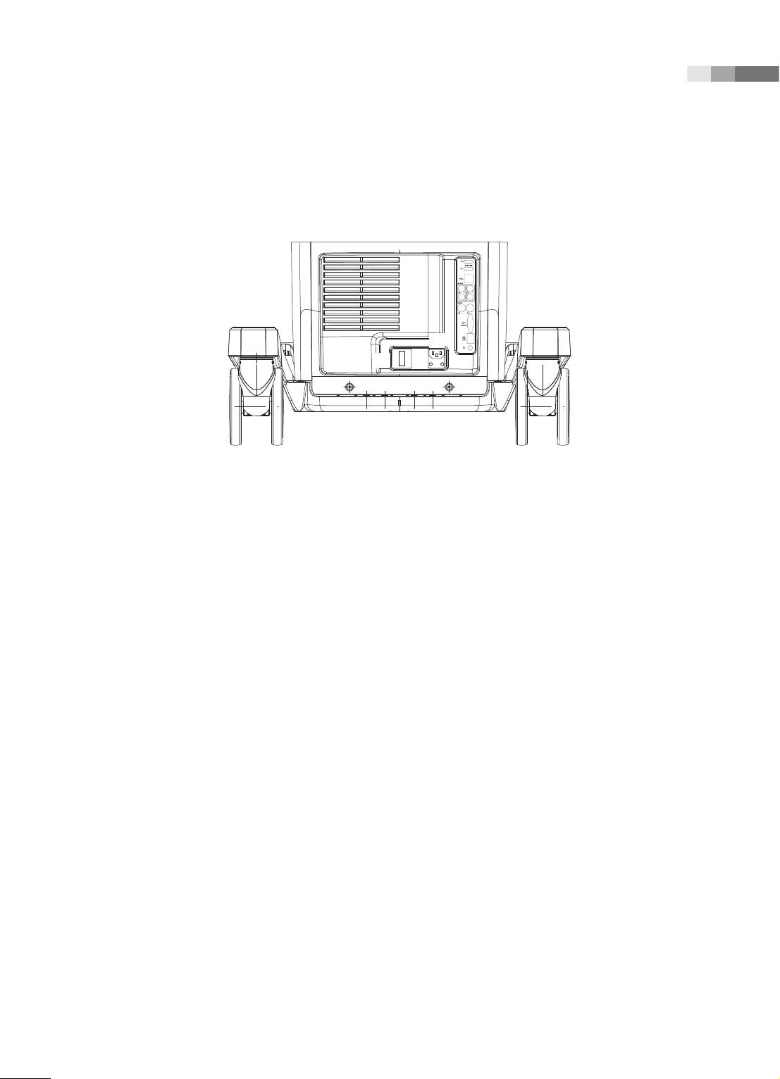
Power Connection Part
The power connection part is located at the bottom on the rear panel.
1
2
3
[Figure 2.8 Power Connection Part]
Chapter 2 Introduction
1 Power inlet: For the power cable to connect to external power
2 Power outlet: Supplies peripheral devices and external devices with power; maximum capacity is
150 VA. Open the rear cover for BW/Color Printer, and you will find the outlet terminal in the DC
power assy.
3 Power switch/breaker: Turns on the power of the product, and cuts off power if overcurrent or
overvoltage occurs.
Probe Holder
Probe holders are mounted at the left and right-hand sides of the control panel.
2-17

User Manual
Peripheral Devices
NOTE: Refer to the user manual of the peripheral device for its operating information.
Internal Peripheral Devices
These are peripheral devices mounted in the system.
DVD-Multi
DVD±R, DVD±RW, DVD-RAM, CD-R, CD-RW
Hard Disc Drive
Min. 500GB SATA-2 2.5” HDD
2-18

Chapter 2 Introduction
External Peripheral Devices
These are peripheral devices that can be connected for use when needed and are connected via the
USB port located at the rear panel.
CAUTION: Do not place peripheral devices that are not listed in this manual in the vicinity of the
patient. If you place them in the patient environment, it may cause an electrical hazard.
1.5m
1.5m
[Figure 2.9 Patient Environment]
CAUTION:
X
When using a peripheral device via a USB port, always turn the power off before connecting/
disconnecting the device. Connecting or disconnecting a USB device while power is turned on
may cause the system and/or the USB device to malfunction.
X
Do not connect additional Peripheral Devices to the auxiliary socket outlets. Connecting to the
auxiliary socket outlet may decrease safety level.
Tips!
When there are two Soft Menus
The console’s USB ports are located on the side panel of the control panel, as well as on the rear
panel of the console.
We recommend that you connect USB storage devices (flash memory media, etc.) to the ports on
the side panel, and connect USB peripheral devices to the rear panel for convenience.
The following products are recommended:
1.5m
2-19

User Manual
Digital Video Printer
X
Black and White: Sony UP-D897, Mitsubishi P95DE
X
Color: Sony UP-D25MD, Mitsubishi CP30DW
USB Printer
HP Officejet 4500, Samsung CLP-620NDK
DVD Recorder
Sony DVO-1000MD
CAUTION:
X
You must install a printer and drivers that are compatible with Microsoft Windows 7 (English
version). Contact Samsung Medison customer support division for inquiries about printer driver
installation.
X
When connecting the printer, ensure that the printer is configured under Microsoft Windows 7
or system setup and has been chosen as the default printer.
X
Please check the port that the printer uses before connecting. Printers should be connected to
the printer port while the USB printer should be connected to the USB port.
Foot Switch
Assign functions to the Foot Switch by going to Setup > Peripherals > Customize Keys > Foot Switch.
You can select from Exit, Freeze, Store, S1, S2, S3, Update, Dual and Quad.
2-20

Chapter 2 Introduction
Probes
Probes are devices that generate ultrasound waves and process reflected wave data for the purpose of
image formation.
NOTE: For detailed information, refer to ‘Chapter 5. Probes’.
Connecting Probes
Be sure to connect or disconnect probes when the power is off to ensure the safety of the system and
the probes.
1. Connect probes to the probe connectors on the front panel of the system. Up to four probes
(options inclusive) may be connected.
2. Turn the connector-locking handle clockwise.
NOTE: If the probe does not connect properly, try reconnecting it after removing any foreign
objects.
[Figure 2.10 Probe Connector]
2-21

User Manual
Accessories
An accessory box containing the items below is supplied with the product.
MANUAL WINDOWS 7 LABEL
SONO GEL
CAP CORD x 2EA
BOLT x 10EA
DRIVER
[Figure 2.11 Accessories]
2-22

Optional Functions
This product has the following optional functions:
Chapter 2 Introduction
S/W
X
MultiVision
X
DICOM
X
4D
X
3D XI
X
Volume NT/IT
X
XI STIC
X
Cardiac Measurement
X
Auto IMT
X
Auto IMT+
X
Needle Mate
X
Panoramic
X
ElastoScan
H/W
X
Gel Warmer
X
Foot Switch
X
e-Motion Marker
X
ODD (Optical Disc Drive)
X
Drawer
X
CW Function
For further information about optional functions, please refer to the relevant chapters in this manual.
2-23


Chapter 3
Utilities
ECG ....................................................................3-3
System Settings ................................................3-5
General System Settings ....................................................... 3-6
General ........................................................................................ 3-6
Patient .......................................................................................... 3-9
Screen Display Settings (Imaging) ..................................3-10
Common ...................................................................................3-11
Application/Preset ................................................................3-13
Measurement Settings ........................................................3-15
Report ........................................................................................3-32
Anatomy ...................................................................................3-33
Comments ................................................................................3-34
Annotation ...............................................................................3-35
Body Marker ............................................................................3-39
Application ...............................................................................3-43
Customize .................................................................................3-45
Touch Menu .............................................................................3-49
Peripheral Device Settings .................................................3-50
Device ........................................................................................3-51
Connectivity Settings ..........................................................3-52
DICOM Settings .....................................................................3-52
Network Settings ..................................................................3-64
Service .......................................................................................3-65
Help.............................................................................................3-65


Chapter 3 Utilities
ECG
If an ECG is installed, the ECG tab will be generated on the touch screen. In a Multi Image Mode such as
Dual or Quad, ECG Cine can be used for each image.
NOTE: You may show or hide the ECG on the screen for each Preset at Setup > Application/Preset
> Preset Setting.
Starting and Finishing an ECG
Tap the ECG button on the touch screen menu to turn the function on or off.
ECG Settings
Sweep Speed
Tap the Sweep Speed button in the touch screen menu to select the ECG display speed. You may
select 18mm/s, 35mm/s, 53mm/s, 71mm/s, 106mm/s or 142mm/s.
Invert
Tap the Invert button on the touch screen menu to turn ECG Invert on or off.
Gain
Adjust the amplitude of the ECG. Rotate the Soft Menu dial-button 1 to adjust the gain between
0-100.
Position
Rotating the Soft Menu dial-button 2 changes the displayed position of the ECG signal. You may
select a position between 0-10; selecting a higher value will position the ECG higher on the screen.
Clip
Rotate the Soft Menu dial-button 3 to select the interval for saving the clip. You can select either
Time or Beat.
3-3

User Manual
Trigger
Tap the Trigger button in the touch screen menu to set up Trigger. You can rotate the Soft Menu
dial-button 4 to select the number of ECG Triggers between 1 and 7.
Trig Delay
Select the time delay between the R-wave and the frame containing the trigger, which applies to
the Trigger function. Rotate the dial-button 4 to select a value between 0 and 3000msec.
Dual Trigger
Tap the Dual Trigger button in the touch screen menu to turn Dual Trigger on or off.
Dual Trig Delay
Select the time delay between the frame containing the first trigger and the frame containing the
second trigger, which applies to the Dual Trigger function. Rotate the dial-button 4 to select a value
between 90 and 3000msec.
CAUTION:
X
If the ECG is less than 30Hz, the Heart Rate (HR) may not be displayed.
X
In CW Mode, when ECG is active, the error ratio of the Heart Rate (HR) should be within 2%.
3-4

Chapter 3 Utilities
System Settings
General system settings that do not have direct bearing on imaging are explained. The setup may be
modified depending on specific needs or preferences.
1. Press Setup button on the keyboard.
2. The Setup screen will appear on the monitor and the touch screen. Select a tab that has items to
specify.
3. Specify settings for each item.
4. Save settings and exit. Click Exit on the monitor screen, or tap Exit on the touch screen, or press
Exit button on the control panel to switch to Scan mode.
[Figure 3.1 Setup - Touch Screen]
3-5

User Manual
General System Settings
In the Setup screen, select the System tab. Or tap System on the touch screen. You can specify general
settings such as title settings.
General
In the Setup screen, select the General tab in the System category.
[Figure 3.2 Setup - System - General]
Location
You can specify the information that is displayed in the title area on the screen.
Institute
Enter the name of the hospital/institution where the product is installed.
Language
Select the system language.
(Supported languages: English, German, French, Spanish, Italian, Russian, Simplified Chinese,
Portuguese)
3-6

Date and Time
The current date is displayed. To change the date, click .
NOTE: You cannot change the date and time when a patient ID has been registered. To change the
date and time, you should finish the current diagnosis by pressing the End Exam button on the
control panel.
Chapter 3 Utilities
Tips!
How to set the date and time
1. Press the Date and Time button in the Date and Time field.
2. Set the date and time using the trackball and the Set button on the control panel. Press the Save
button to apply the settings. To cancel, press Cancel or press the Exit button on the control panel.
3. To change the time zone, press the Time Zone button.
4. The Time Zone Settings window will be displayed. Select the time zone by using the combo
button. Press the OK button to apply the settings. To cancel, press Cancel or press the Exit button
on the control panel.
[Figure 3.3 Date and Time]
Date Format
Specify the date format. Select a date format using the combo button. The selected date format will
be applied to various date fields in Patient Information.
Time Format
Specify the time format. Select a desired time format (12 Hour or 24 Hour) by pressing the combo
button.
3-7

User Manual
Trackball Speed
Scan Mode
Specify the trackball speed as Slow, Normal, or Fast.
Measurement
Specify the trackball speed as Slow, Normal, or Fast.
Slower speeds allow more precise measurements.
Display
Screen Saver
Select the wait time (in minutes) for the screen saver.
System Power Button
X
Ask me what to do: Select from Shut Down, Restart or Cancel.
X
Shut Down: The power will turn off.
Option
X
Auto Freeze (20min): The screen automatically freezes in 20 minutes.
X
Show Save Prompt on Exit: Use the check box to select whether to save or not.
X
Boot up Caps Lock On: Use the checkbox to select whether to enter capital letters.
Beeper Off
X
Control Panel: Turns off the beeper sound for manipulating the control panel.
X
Touch Screen: Turns off the beeper sound for manipulating the touch screen.
Video Settings
Format
Select either NTSC or PAL.
3-8

Patient
In the Setup screen, select the Patient tab in the System category.
Chapter 3 Utilities
[Figure 3.4 Setup - System - Patient]
Patient Data
Name Display
X
Last, First Middle: Display the name of the patient in the order of last name, first name, then
middle name.
X
First Last Middle: Display the name of the patient in the order of first name, last name, then
middle name.
Title Display
X
Show or hide patient information in the Title area of the screen.
X
None: Patient information is not displayed.
X
Date of Birth: Displays the patient's date of birth.
X
Age: Displays the patient's age.
X
Gender: Select this checkbox to display the patient's gender. Note that the patient's gender can
only be displayed if their birthday or age is displayed as well.
3-9

User Manual
User Dened List
You may enter information related to studies beforehand, so that you can assign the information easily
when entering patient information. Use the Add, Change, Delete, Delete All, Up, and Down buttons
to add, edit, or delete information; you may create a list of up to 20 for each item.
Operator
You can save the name of the operator who scans the patient.
Indication
You can save information on the patient's medical history.
Diag. Physician
You can save the name of the physician who diagnosed the patient.
Ref. Physician
You can save the name of the referring physician.
Description
You can save up to 20 diagnostic memos per application.
Screen Display Settings (Imaging)
In the Setup screen, select the Imaging tab. Or tap Imaging on the touch screen. Specify display-related
options.
3-10

Chapter 3 Utilities
Common
Common settings apply to all applications.
You can select multiple items. Use the trackball and the Set button to select and check or uncheck an
item.
[Figure 3.5 Setup - Imaging - Common]
General Setting
HPRF
In PW Spectral Doppler mode, this detects blood flow with a velocity that exceeds the maximum
speed at the depth you want to obtain the Sample Volume from.
Preferred Probe Port
Select the Probe Port that takes the highest priority when the system starts or when you select a
probe.
Color Velocity Unit
Select the units of velocity in Color Mode.
Doppler Scale Unit
Select the units of measurement for the axis scale in Spectral Doppler Mode.
3-11

User Manual
Display Setting
Show Image Info
Show or hide the image information. If the image is obscured by the image information, disable this
option to hide the image information.
Show Horizontal Scale Bar
Show or hide the Horizontal Scale Bar in the Scan UI.
Display Tx Frequency
Specify how to display the Tx Frequency for each probe. If checked, the current state will be
displayed in MHz; if unchecked, the state will be indicated as PEN, GEN, or RES.
TGC window Auto Close (sec)
Specify the time that must elapse before the TGC Control Window in the touch screen automatically
closes because of a lack of user input. If set to Off, the window will not close automatically.
TGC Curve Display
Specify how long the TGC Curve is displayed for in Scan UI (On: Always displayed, Off: Never
displayed, Auto: Displayed for a specific length of time and then disappears).
Biopsy Guideline Type
Select the type of Biopsy Guide Line displayed.
3-12

Chapter 3 Utilities
Application/Preset
These settings are applied specifically to the selected application.
You can select multiple items. Use the trackball and the Set button to select and check or uncheck an
item.
[Figure 3.6 Setup - Imaging - Application/Preset]
Application Setting
Select Application
Select the application.
Seamless Dual Mode
Select whether or not to use Seamless Dual Mode in Dual Mode.
Enable Doppler Cursor Mode
Select whether or not to enter Cursor mode before Doppler mode.
Enable M Cursor Mode
Select whether or not to enter Cursor mode before M mode.
3-13

User Manual
Activated Mode When Image Is Frozen
Select the mode to activate upon freezing an image.
One of the following modes may be selected: Cine, Measurement, Annotation, or Body Marker.
Preset Setting
Select Preset
Check the Probe, Application, and Preset.
ECG
Enable or disable ECG for each Preset.
Keep PRF in Doppler Simultaneous Mode
Select this checkbox to keep the PRF value while measuring blood flow velocity in Simultaneous
Mode without using Doppler Mode.
NOTE: This feature is available for the following probes and applications:
X
CF2-8, CS1-4, C2-8, CA2-8AD, CA1-7AD: OB, Abdomen
X
3D2-6, VE4-8, CV1-8AD: OB
X
3D4-9, V5-9, EVN4-9, ER4-9, VR5-9: OB, GYN
X
CF4-9, L5-13, LF5-13, LA3-14AD: Vascular
Thermal Index Type
Specify the TI to display on the screen as TIs (Soft Tissue Thermal Index), TIb (Bone Thermal Index),
or TIc (Cranial Bone Thermal Index). You may specify indices by Preset.
3-14

Chapter 3 Utilities
Measurement Settings
Specify various setup options for measurements. The setup may be modified depending on specific
needs or preferences.
1. Press Setup on the keyboard. When the Setup screen is displayed, select the Measurement tab.
2. When the Measurement screen appears, select the tab that contains the items you wish to congure.
3. Specify settings for each item.
4. Press the Save button to save the settings. You can click Exit on the monitor screen or tap Exit on
the touch screen to exit the Setup screen and switch to Scan Mode.
General Settings
In the Setup screen, select the General tab in the Measurement category.
You can specify basic measurement options.
[Figure 3.7 Setup - Measurement - General]
3-15

User Manual
Menu
Directions
Select the Direction Type applied to the target to measure in the initial system status. The options
are Left and Right.
Location
Select the Location Type applied to the target to measure in the initial system status. The options
are Prox, Mid, and Dist.
Hide the menu on Unfreeze
Hide or show the Measurement menu on the screen after taking measurements. Show Scan Mode
(On) or hide the Measurement menu (Off).
Cursor
Cursor Type
Select the shape of the default caliper cursor displayed on the screen. Select between ‘Cross’ shape
(+) and ‘X’.
Arrow Head Marker
Show or hide the Head Marker when measuring a small area.
Cursor Size
Select the size of the default caliper cursor displayed on the screen. The options are Small, Medium,
and Large.
Display
2D Line Type
Select the type of line to use for measurement in 2D mode (Solid: Solid line, Dot: Dotted line, None:
Start and end points).
3-16

Chapter 3 Utilities
Ellipse Cross Line
Show (On) or hide (Off) the long axis and the short axis of an ellipse while taking Ellipse
measurements.
Clear Measurement(s) on Unfreeze
Hide or show measurement results on the screen when switching to Scan Mode after taking
measurements. Select this checkbox to show measurement results in 2D or M/D Mode.
Distance
Choose how the average is displayed on screen when linear distances are measured in succession.
X
Avg (2Dist): Show the average of two consecutive linear distance measurements.
X
Avg (All): Show the average of all consecutive linear distance measurements.
Measurement Units
Specify the measurement units. For a small object, it is more convenient to use ‘mm’ for Dist. When
blood flow is fast, it is better to use ‘m/s’ for Vel.
X
Dist: Choose between cm and mm scales for the distance, area, and volume unit.
X
Vel: Select the unit of velocity - cm/s or m/s.
NOTE: Changing the measurement unit erases all measurements that may have been taken.
Key
Set Measurement on Store
Turn on or off the function that automatically completes measurements when the Store key on the
control pad is pressed while a measurement is being taken.
Set Measurement on Unfreeze
Turn on or off the function that automatically completes measurements when the image switches
to Scan mode while a measurement is being taken.
3-17

User Manual
Result
Select how measurement results are displayed.
Position On 2D:
Reposition the measurement results when 2D mode is selected.
X
Left-Top: Measurement results are displayed in the top left corner of the screen.
X
Left-Bottom: Measurement results are displayed in the bottom left corner of the screen.
X
Right-Bottom: Measurement results are displayed in the bottom right corner of the screen.
X
Right-Top: Measurement results are displayed in the top right corner of the screen.
X
Custom: Measurement results are displayed in a location selected by the user.
Position on D/M
Moves the measurement results.
X
Left-Top: Moves the measurement results towards the top left corner of the screen.
X
Left-Bottom: Moves the measurement results towards the bottom left corner of the screen.
X
Right-Bottom: Moves the measurement results towards the bottom right corner of the screen.
X
Right-Top: Moves the measurement results towards the top right corner of the screen.
X
Custom: Measurement results are moved to a location selected by the user.
Show Background
Turn the background of the measurement results transparent (On) or opaque (Off).
Font Size
Select the size of the font used for the measurement results.
3-18

Chapter 3 Utilities
Caliper
On the Setup screen, select the Caliper tab in the Measurement category.
Specify whether additional information will be shown along with the basic measurement values, when
basic measurements are taken by pressing the control panel’s Caliper button. If this option is selected,
the additional information will also be saved and output along with the measurement results.
Setting ‘Application’ to General will change the items in ‘D Trace’. Setting ‘Application’ to Cardiac will
change the items in ‘D Trace’ and ‘D Velocity’
NOTE: ‘Cardiac’ setting can only be used when the probe preset is Cardiac.
[Figure 3.8 Setup - Measurement - Caliper]
3-19

User Manual
Applications
In the Setup screen, select the Applications tab in the Measurement category.
[Figure 3.9 Setup - Measurement - Application]
Application
Select an application.
Caliper
Caliper then Assign
After taking a Basic Measurement, the measurement result may be set as a Label. Enable or disable
this by choosing from ‘On/Off’.
Default Tool
Select the default tool that functions in the measurement cursor state for each Image mode.
X
2D Mode: Distance, Trace Length, Open Spline, Ellipse, Trace, Closed Spline, Angle, Distance
Steno(D), Trace Steno(D), Ellipse Steno(A), Trace Steno(A), Spline Steno(A), 1 Dist Volume, 2 Dist
Volume, 3 Dist Volume, Ellipse Volume, Ellipse+ Dist Vol, Distance, Ellipse trace Steno(A)
3-20
X
D Mode: Velocity, Acc, Auto Trace, Manual Trace, Limited Trace, HR, RI, Dist Vol. Flow(D), Trace
Vol. Flow(D), Spline Vol. Flow(D), Ellipse Vol. Flow(A), Trace Vol. Flow(A), Spline Vol. Flow(A), Time
X
M Mode: Distance(M), Slope, HR,Time(M)

Chapter 3 Utilities
Default Tool Category
Select the default tool for each measurement category.
X
Volume: 1 Dist. Volume, 2 Dist. Volume, 3 Dist. Volume, Ellipse Volume, Ellipse + Dist. Vol
X
%Stenosis(D): Distance Steno(D), Trace Steno(D), Spline Steno(D)
X
%Stenosis(A): Ellipse Trace Steno(A), Ellipse Steno(A), Trace Steno(A), Spline Steno(A)
X
Volume Flow: Volume Flow(D), Volume Flow(A)
X
Doppler Trace: Manual Trace, Limited Trace
Doppler
Display Absolute Value
The doppler measurement is displayed as an absolute value.
RI Calculation Method
Select whether to use ED or MD when calculating the value of RI.
Doppler Auto Calculation Items
Select which value to measure and display on the screen in measurement mode using the Auto
Doppler Trace Tool.
Doppler Results
Set up the Doppler measurement items to be displayed together with the measurement results
measured by using the Auto Doppler Trace Tool.
Heart Rate
X
Cycle: Select the number of heart rate (HR) cycles.
X
Manual: Enter the heart rate manually when conducting an exam.
X
Automatic: Heart rate is entered automatically by the ECG while conducting an exam.
3-21

User Manual
Additional Results
In the Setup screen, select the Additional Results tab in the Measurement category.
[Figure 3.10 Setup - Measurement - Additional Results]
Application
Select an application.
OB
X
SD/Percentile Type: Select None, SD, or Percentile.
X
NT Marker: Select the indicator symbol for measuring NT. You may select either CrossHair or Bar
type.
GYN
Default Follicle Tool: Select a method for measuring the size and volume of follicles. You may select
1 Distance Volume, 2 Distance Volume, 3 Distance Volume, Ellipse Volume, or Ellipse + Dist Vol.
Vascular
ICA/CCA Ratio: Select a measurement item to use to calculate the ICA/CCA ratio. You may select
Max, Prox, Mid, or Dist as PS and ED for ICA and CCA, individually.
3-22
 Loading...