

Samsung Galaxy S4, GT-I9295 Schematics
Level
7.
Disassembly and Assembly Instructions
7-1.
Repair
2
7-1-1.
1)
2)
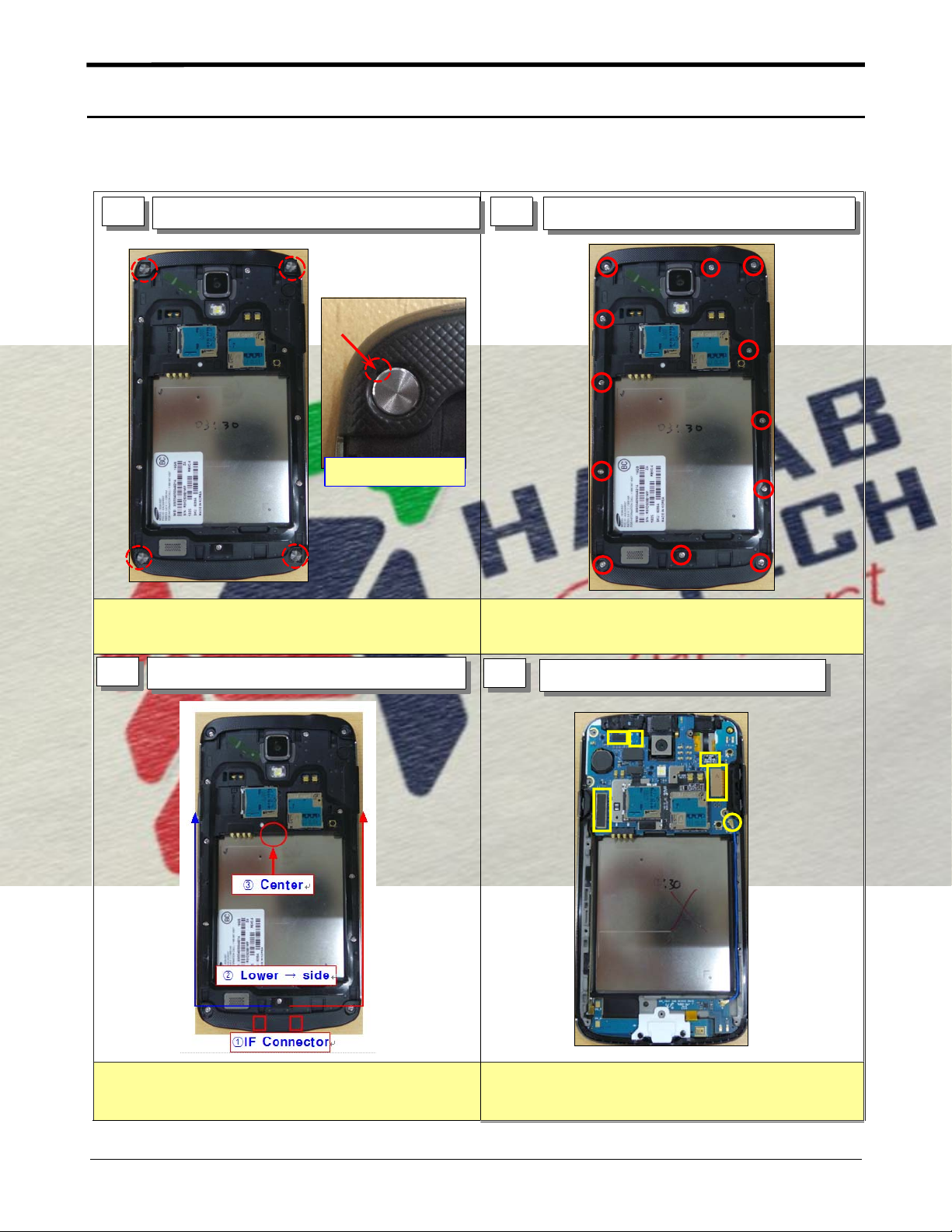
Disassembly
1 2
Disassemble SCREW CAP
Tweezer insert point
Be careful not to make scratch and molding damage!
Detach Screw cap4point using tweezers.
Release Screw12Point at REAR
Be careful not to make scratch and molding damage!
1)
Release Screw12point
2)
3
Disjoint Hook at REAR // Disassemble REAR
Disassemble Rear in oder.
1)
4
Disassemble FPCB and PBA
Be careful nottoscratch FPCB
1)
Hold up Main PBA from bottom.
2)
7-1
Confidential and proprietary-the contents in this service guide subject to change without prior notice.
Distribution, transmission, or infringement of any content or data from this document without Samsung’swritten authorization is strictly prohibited.
Level2Repair
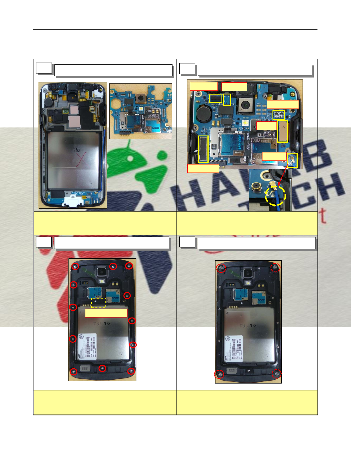
7-1-1.
1
Assembly
SetaPBA and FRONT Ass'y.
2
Assemble PBA and FPCB
①VT CAM
⑥SUB PBA
Assemble PBA on Front Ass'y
1)
Assemble FPCB6point
2)
②Sensor
③SVC LED
④LCD
⑤COAX
3
Assemble Rear and Screw.
Press this point
Drive Screws at12points with torque
1)
1.5±0.1
Kgf/
㎠
4
Assemble Screw cap
Assemble Screw cap4point.
1)
7-2
Confidential and proprietary-the contents in this service guide subject to change without prior notice.
Distribution, transmission, or infringement of any content or data from this document without Samsung’swritten authorization is strictly prohibited.
 Loading...