

Samsung g530h Disassembly & Reassembly
Level
7.
Disassembly and Assembly Instructions
7-1.
Repair
2
7-1-1.
※ Caution
1) Be care of scratch and molding damage.
3
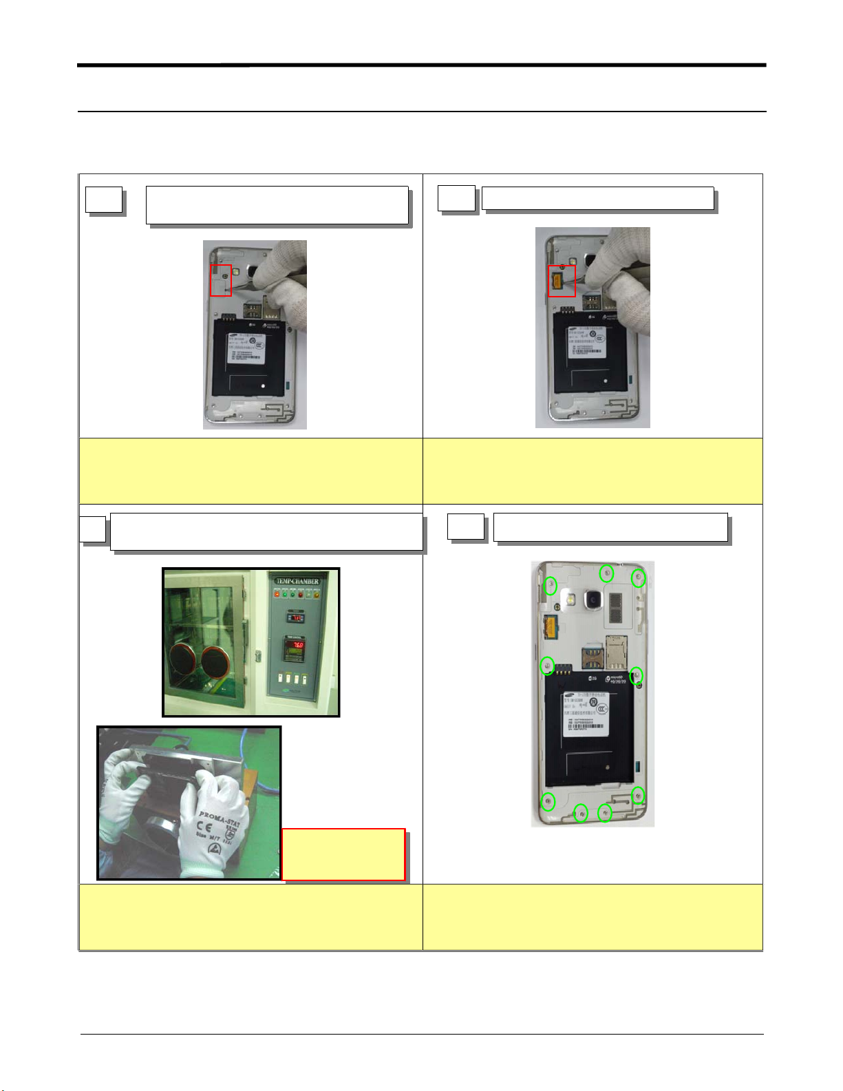
Disassembly
1
1) Disassemble LCD connector protect
cover
1) Displace the temperature chamber for 10 minute
2) Detach the TSP/LCD Assay using Vaccum jig
2
1) Separate the LCD connector
※ Caution
1) Be care of scratch and molding damage
2) Be care of damage to the LCD FPCB and PBA
4
1) Unscrew the 9 points
AIR pressure
5~7 kgf/cm
※ Caution
1) Before disassembling, Use heating chamber.
2) Be care of scratch and molding damage.
Confidential and proprietary-the contents in this service guide subject to change without prior notice.
Distribution, transmission, or infringement of any content or data from this document without Samsung’swritten authorization is strictly prohibited.
※ Caution
1) Be care of scratch and molding damage.
7-1
Level2Repair
5
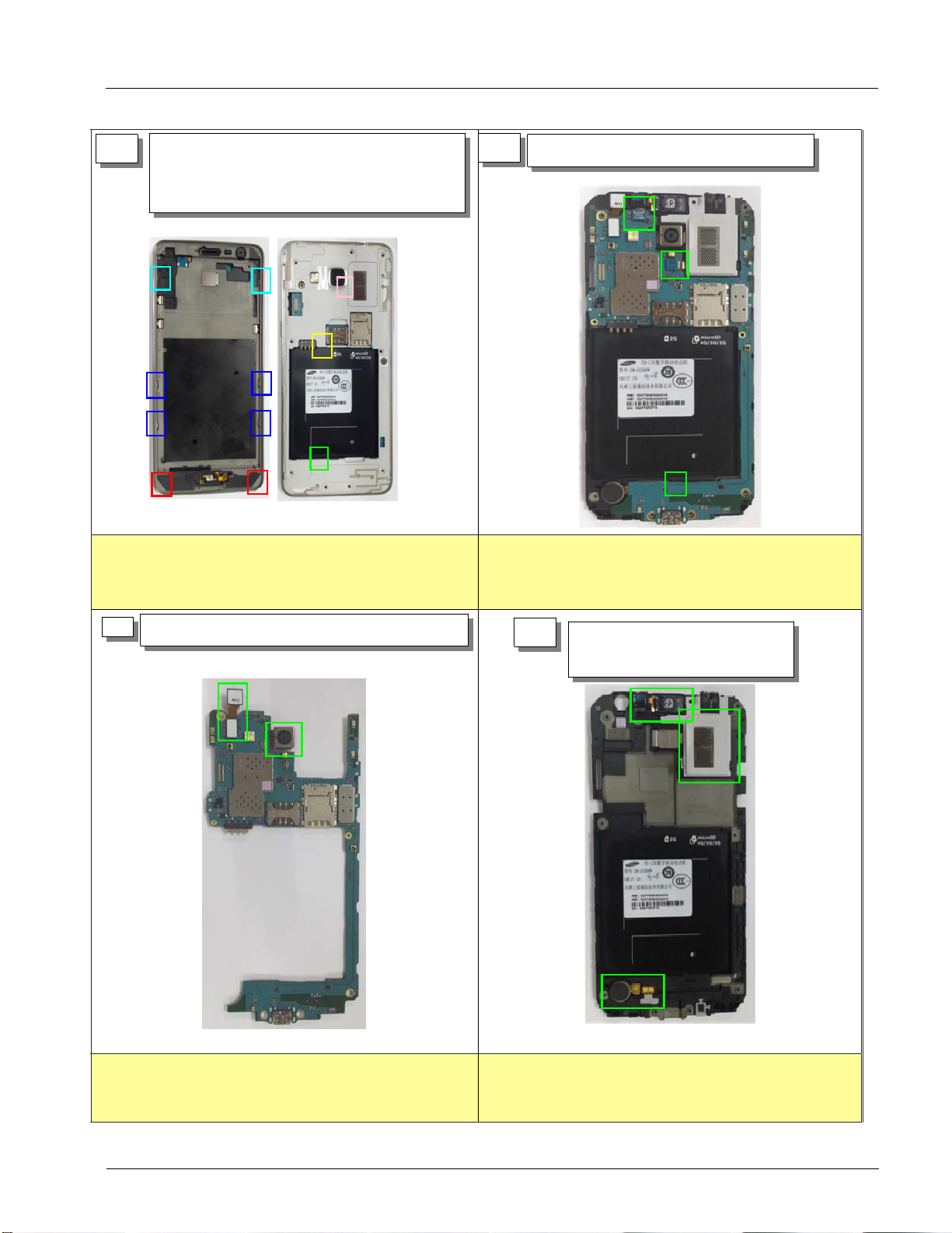
1) Release the 11 hooks according to a
guide
2) Detach the REAR and Bracket Assy
⑨
⑩
⑪
⑧
③
④
⑤
⑥
⑦
①
②
※ Caution
1) Be care of damage to the Bracket
2) Be care of damage to the PBA Assy
6
1) Detach the Bracket Assay from Rear.
※ Caution
1) Be care of damage to RCV module, SPK
2) Be care of damage to the part's FPCB
7
1) Separate the VT, MEGA Camera from PBA
※ Caution
1) Be care of damage to the part's FPCB
8
1) Separate the RCV, Motor,
Speaker from hook
※ Caution
1) Be care of scratch, molding damage and part
7-2
Confidential and proprietary-the contents in this service guide subject to change without prior notice.
Distribution, transmission, or infringement of any content or data from this document without Samsung’swritten authorization is strictly prohibited.
 Loading...