

SAMSUNG FAXF700ATGXIL Service Manual

FACSIMILE
SF700AT
CONTENTS
1. Precautions
2. Specification
3. Operating Instructions
4. Disassembly and Reassembly
5. Circuit Description
6. Troubleshooting
7. Electrical Parts List
8. Exploded Views and Parts List
9. PCB Diagrams
10. Block Diagram
11. Wiring Diagram
12. Schematic Diagrams
FACSIMILE
SERVICE
Manual

Samsung Electronics Co.,Ltd. APR. 1998.
Printed in Korea.
JF68-60A
ELECTRONICS

7. Product Safety Notice:
Some electrical and mechanical parts have
special safety-related characteristics which
might not be obvious from visual inspection.
These safety features and the protection they
provide could be lost if a replacement
component differs from the original. This
holds true, even though the replacement may
be rated for higher voltage, wattage, etc.
Components critical for safety are indicated in
the parts list with symbols . Use only
replacement components that have the same
ratings, especially for flame resistance and
dielectric specifications. A replacement part
that does not have the same safety
characteristics as the original may create
shock, fire, or other safety hazards.
SF700AT 1-1
1. Be sure that all built-in protective devices are
in place. Restore any missing protective
shields.
2. Make sure there are no cabinet openings
through which people- particularly childrenmight insert fingers or objects and contact
dangerous voltages.
3. When re-installing chassis and assemblies, be
sure to restore all protective devices, including
control knobs and compartment covers.
4. Design Alteration Warning:
Never alter or add to the mechanical or
electrical design of this equipment, such as
auxiliary connectors, etc. Such alterations and
modifications will void the manufacturer's
warranty.
5. Components, parts, and wiring that appear to
have overheated or are otherwise damaged
should be replaced with parts which meet the
original specifications. Always determine the
cause of damage or overheating, and correct
any potential hazards.
6. Observe the original lead dress, especially near
sharp edges, AC, and high voltage power
supplies. Always inspect for pinched, out-ofplace, or frayed wiring. Do not change the
spacing between components and the printed
circuit board.
1. Precautions
Follow these safety, ESD, and servicing precautions to prevent personal injury and equipment damage.
1-1 Safety Precautions

1-2 ESD Precautions
Certain semiconductor devices can be easily damaged by static electricity. Such components are commonly
called "Electrostatically Sensitive (ES) Devices", or ESDs. Examples of typical ESDs are: integrated circuits,
some field effect transistors, and semiconductor "chip" components.
The techniques outlined below should be followed to help reduce the incidence of component damage
caused by static electricity.
Precautions
1-2 SF700AT
CAUTION: Be sure no power is applied to the
chassis or circuit, and observe all other safety
precautions.
1. Immediately before handling a semiconductor
component or semiconductor-equipped
assembly, drain off any electrostatic charge on
your body by touching a known earth ground.
Alternatively, employ a commercially
available wrist strap device, which should be
removed for your personal safety reasons prior to
applying power to the unit under test.
2. After removing an electrical assembly
equipped with ESDs, place the assembly on a
conductive surface, such as aluminum or
copper foil, or conductive foam, to prevent
electrostatic charge buildup in the vicinity of
the assembly.
3. Use only a grounded tip soldering iron to
solder or desolder ESDs.
4. Use only an "anti-static" solder removal device.
Some solder removal devices not classified as
"anti-static" can generate electrical charges
sufficient to damage ESDs.
5. Do not use Freon-propelled chemicals. When
sprayed, these can generate electrical charges
sufficient to damage ESDs.
6. Do not remove a replacement ESD from its
protective packaging until immediately before
installing it. Most replacement ESDs are
packaged with all leads shorted together by
conductive foam, aluminum foil, or a
comparable conductive material.
7. Immediately before removing the protective
shorting material from the leads of a
replacement ESD, touch the protective material
to the chassis or circuit assembly into which
the device will be installed.
8. Maintain continuous electrical contact between
the ESD and the assembly into which it will be
installed, until completely plugged or soldered
into the circuit.
9. Minimize bodily motions when handling
unpackaged replacement ESDs. Normal
motions, such as the brushing together of
clothing fabric and lifting one's foot from a
carpeted floor, can generate static electricity
sufficient to damage an ESD.
1. Exercise caution when replacing a Lithium
battery. There could be a danger of explosion
and subsequent operator injury and/or
equipment damage if incorrectly installed.
2. Be sure to replace the battery with the same or
equivalent type recommended by the
manufacturer.
3. Lithium batteries contain toxic substances and
should not be opened, crushed, or burned for
disposal.
1-3 Lithium Battery Precautions
2. Specification
2-1 Transmitter
210 x 297 mm
257 x 1500 mm
148 x 180 mm
0.085 x 0.115 mm
B4 paper,2056 scan elements along 257 line length
A4 : 208 mm, B4 : 252 mm
Flat-bed scanning using CIS
Intermittent scanning by stepping motor
203 pels/in (8 dots/mm)
Super Fine 3.85 lines/mm
Fine 7.7 lines/mm
Standard 15.4 lines/mm
SF700AT 2-1
Parameter Specification
Normal
Max.
Min.
Horizontal
Vertical
Horizontal
Vertical
Document Size
Document Thickness
Scan Line Length
Effective Scanning Width
Scanning Method
Resolution
MH (Modified Huffman)
B4/A4 x 30 m, core 12.7 mm diametre
252 mm
Thermal recording with solid state Thermal Printing Head
203 pels/in (8 dots/mm)
Super Fine 3.85 lines/mm
Fine 7.7 lines/mm
Standard 15.4 lines/mm
Parameter Specification
Horizontal
Vertical
Coding Scheme
Recording Paper Size
Effective Recording Width
Recording Method
Resolution
2-2 Receiver

Specifications
2-2 SF700AT
Public Switched Telephone Network (PSTN)
Direct coupling
9600, 7200, 4800, 2400 bps
QAM, DPSK and FSK
(V.29, V.27ter with fall back function and V.21)
1700 Hz (9600/7200 bps)
1800 Hz (4800/2400 bps)
1100 Hz (CNG)
2100 Hz (CED)
300 bps (FSK)
0 dBm to -15 dBm +0.0/-3 dBm, adjustable 1 dB steps
0 dBm to -43 dBm
600 ohm +/- 30%
Parameter Specification
Communication Facility
Line Coupling
Transmission Speed
Modem
Carrier Frequency
Control Signal
Output Level
Input Sensitivity
Input & Output Impedance
2-3 Line Control Block
DP/DTMF
Direct dialing, Memory dialing, Redialing
10 memory dial (power on)
Check Power Label attached near the power outlet
50 to 95 °F (10 °C to 35 °C)
20 to 80 % RH (Non-Condensing)
305 X 116 X 243 mm
3.9 Kg
Parameter Specification
Dialling Signal
Dialling Method
Memory Capacity
Power Requirement
Temperature
Relative Humidity
Dimension
Weight
2-4 Others

SF700AT 3-1
3. Operating Instructions
3-1 How To Enter Service Mode
In service (Tech) mode, the technician can check the machine and perform various test to isolate the cause of
a malfunction.
To enter service mode, press MENU, #, 1, 9, 3, 4 in sequence, and 'TECH' will be displayed in the LCD to
confirm that the machine has entered service (tech) mode. While in service mode, the machine still performs
all normal operations. To return to normal user mode, press 'MENU, #, 1, 9, 3, 4' in sequence again, or turn
the power switch off, then on by plugging the power cord out, then in.
Options changed while in service mode do not remain changed, unless you first clear machine memory.
3-2 Changing Options
3-2-1 Selectable Options
GRAY SCALE LEVEL
Choose either 16 or 64 gray scale levels. The
selected level is also used in the photo sending
mode. If you select 64 levels, transmission time is
longer, however the result at the receiving end
will be superior. This mode works only when the
remote machine is capable of super-fine mode.
CONFIRMATION REPORT PRINTOUT
Select whether a confirmation report prints each
time a user sends a fax.
YES: The machine prints out the report
automatically after each fax sent.
ERROR : The machine prints a report only when
there is an error.
NO: The machine does not print the report
automatically. User can print the list on
demand.
RING BEFORE ANSWER
Select the number of rings the machine allows
before it answers a call in automatic receiving
mode.
PAPER CUTTING
Choose cutting or non-cutting mode.
Choose YES to cut the paper automatically after
each document received or copied.
Choose NO to print a tear line and not to cut the
paper.
FAX FORWARD
With this feature activated, the machine
automatically transfers incoming fax received in
the automatic receiveing mode to a specified
remote fax machine.
Choose YES to turn on this feature and enter the
remote fax number you want to be forwarded.
Choose NO to turn off the feature.
CALL TRANSFERRING
This feature allows the fax machine to transfer
incoming caller's message to a specified remote
location.
Choose YES to turn on this feature. The LCD
display asks to enter the telephone number you
want to be transferred.
Choose NO to turn off the feature.

Operating Instructions
3-2 SF700AT
CALL MONITORING
This feature enables you to hear callers leaving
messages on the machine.
Choose YES to turn on this feature.
Choose NO to turn off this feature.
TOLL SAVER
This feature lets the user dial into this machine
from a remote phone and check whether anyone
has left a message without being charged for a
charge call. When toll saver is on and there are
messages waiting to be heard, the machine
answers on the number of rings you specify in the
ring count option. If there are no messages, the
machine answers on the second ring after the
number specified. This gives the user time to hang
up the phone before the machine answers - and
saves the price of the call.
Choose YES to turn on this feature.
Choose NO to turn off this feature.
MESSAGE RECORDING TIME
You can select the maximum time allowed for
caller messages and memos.
If you choose YES, the LCD display shows you the
time limits available. Choose the proper time. If
you choose 0, it allows callers to hear the greeting
message but doesn't permit them to leave
messages.
REMOTE PASSWORD CODE
You can change the two-character password used
to access your machine from a remote phone. The
password is preset to "#19#" (pound one nine
pound) at the factory. The first and the last #'s are
fixed, but you can change the middle numbers
from 01 to 98. The machine doesn't accept double
character codes (11, 22, etc.) as passwords, because
line conditions can occasionally make the machine
fail to recognize a double digit code.
Enter the characters you want to use, then press
START.
BATTERY ALARM
You can turn on the battery alarm feature. With
this feature on, the machine displays the low
battery message in the LCD and sounds beeps to
alert you low battery condition.
Choose YES to turn on the battery alarm feature.
Choose NO to turn off the battery alarm feature.
SILENCE CHECK
In TAD mode, The machine decides the next
action when detected a silence of 10 seconds.
The actions are:
RCV: Swiches to receive mode.
RECORD: Keeps the recording the silence.
CUT: Disconnect the line and returns to standby
mode.
MODEM SPEED
Select baud rate of 9600, 7200, 4800, or 2400 bps.
The lower the baud rate, the larger the acceptable
error rate. T30 protocol has a fixed speed of 300
bps in the protocol mode. When the TX speed is
set to 9600 or 7200 bps, the RX speed will be either
V.29 or V.27 ter. When the TX speed is set to 4800
or 2400 bps, the RX speed will be V.27 ter.
MONITOR LINE
You can hear line signals through a tone speaker.
The volume is adjustable.
Choose YES to monitor the line signal.
Choose NO to turn off this feature. Speaker will be
active only for dialing, the starting part of the
phase B of CCITT, and key tones.
TRANSMISSION LEVEL
You can set the transmission level to between
0 and -15 dBm in 1 dB steps using the control
panel keypad.
Accuracy is + 0 /-3 dBm.

Operating Instructions
SF700AT 3-3
RECEPTION LEVEL
Reception level may be too low due to cable losses.
If set to -43 dBm, reception sensitivity will be
between 0 and -43 dBm.
If set to -48 dBm, reception sensitivity will be
between 5 and -48 dBm.
CABLE EQUALISER
Copper telephone wire attenuates low frequencies
less than high frequencies. The longer a cable is,
the more pronounced the effect. To compensate for
this attenuation you may need to set the machine
to match the cable length currently used. Select
short or long.
BUSY ON DROP OUT TIME
While checking busy on time, if any signal noise is
detected, the machine will ignore the signal noise
unless it is greater than a specified time.
BUSY OFF DROP OUT TIME
While checking busy off time, if any signal noise is
detected, the machine will ignore the signal noise
unless it is greater than a specified time.
FLASH TIME
This feature allows you to change the recall time.
BUSY TONE DETECTION LEVEL
While checking tone in ANS/FAX mode, If any
signal which is great than set level is detected for a
few seconds the machine will disconnect the line.
3-2-2 Changing Options
ress MENU, 3, START/COPY in sequence.
Press < or > to select the desired option item.
When the desired option item appears, press
START and use > or < to change the status of a
selected function.

3-4 SF700AT
3-3 Test Mode
Test mode is used to test machine functions. To enter test mode, press MENU, 0, START/COPY buttons in
sequence.
Operating Instructions
TPH TEST
You can print a TPH test pattern and check the
heating element of TPH with this test pattern.
MODEM TEST
The modem will send various transmit signals on
the telephone line. You can check the following:
¥ FSK test
¥ tones: 1100 Hz, 1650 Hz, 1850 Hz, 2100 Hz
¥ G3 training: 9600, 7200, 4800, 2400 bps
DTMF TEST
The machine tests its DTMF (Dual Tone Multi
Frequency). When you press any key on the
keypad, including and #, you will hear the
corresponding key tone.
LINE PATH TEST
Tests the telephone line loop.
ROM TEST
Tests machine ROM (Read Only Memory). The
result and the software version appear in the LCD
in the following format:
CHKSUM= XX, VXX, OK
MEMORY CLEAR
Erases contents of RAM. When memory is cleared,
the machine returns to default settings.

Operating Instructions
SF700AT 3-5
3-4 Report Printout
A number of useful reports can be printed in service mode. One of these lists is the protocol list, which
contains detailed information which may be required when contacting technical support. To print this list,
press MENU, 4, START/COPY in sequence.
When a report name appears in the display, scroll through the list of reports by pressing < or >. When a
desired report is selected, press START/COPY.
CONFIRMATION REPORT
Shows the last transmission result .
MEMORY INFORMATION REPORT
Shows a specific information on memory
transmission currently registered in memory.
VOICE STATUS REPORT
Shows the status of the recorded voice messages.
TRANSMISSION JOURNAL
Shows information about faxes sent.
RECEPTION JOURNAL
Shows information about faxes received.
TELEPHONE NUMBER LIST
Lists all numbers stored in the machine's onetouch and speed dialling memory.
SYSTEM DATA LIST
Shows all options that were set in user mode and
service mode.
PROTOCOL LIST
This list is available in the service mode only, and
shows the sequence of the CCITT group 3 T.30
protocol during the most recent TX or RX
operation. You can check for send and receive
errors with this list.
If a communication error occurs while the machine
is in service mode, the protocol list will print
automatically.
HELP LIST
This report illustrates the machine's basic
functions and commands. Use as a quick reference
guide.

Operating Instructions
3-6 SF700AT
3-5 LCD Display
3-5-1 During communication
In user mode, the LCD shows the remote
machine's TTI number, communication type,
(send or receive), and page number.
In service mode, the display shows the
communication type, abbreviations for the CCITT
Group 3 T.30 protocol as they occur, the protocol
type (G3), coding type (MH), baud rate in kbps,
and line time.
3-5-2 If a communication problem
occurs:
In user mode, the display shows one of the
following reasons: PAPER JAM, CUTTER JAM,
SEND ERROR, or RECEIVE ERROR.
In service mode, the display shows all error
messages available in user mode, as well as
additional error messages not available in user
mode.
Error messages shown in service mode only are as
follows:
PRE-MESSAGE ERROR:
problem occurred during phase B of session
MESSAGE ERROR:
problem occurred during phase C of session
POST-MESSAGE ERROR:
problem occurred during phase D of session
LINE ERROR:
machine cannot connect or has lost connection
with the remote machine
Additional messages, not shown above, will
appear in the transmission and reception journals
printed in service mode.

SF700AT 4-1
4. Disassembly and Reassembly
Note: Make sure power is OFF, and unplug the power cord from the wall outlet.
4-1 Main Chassis
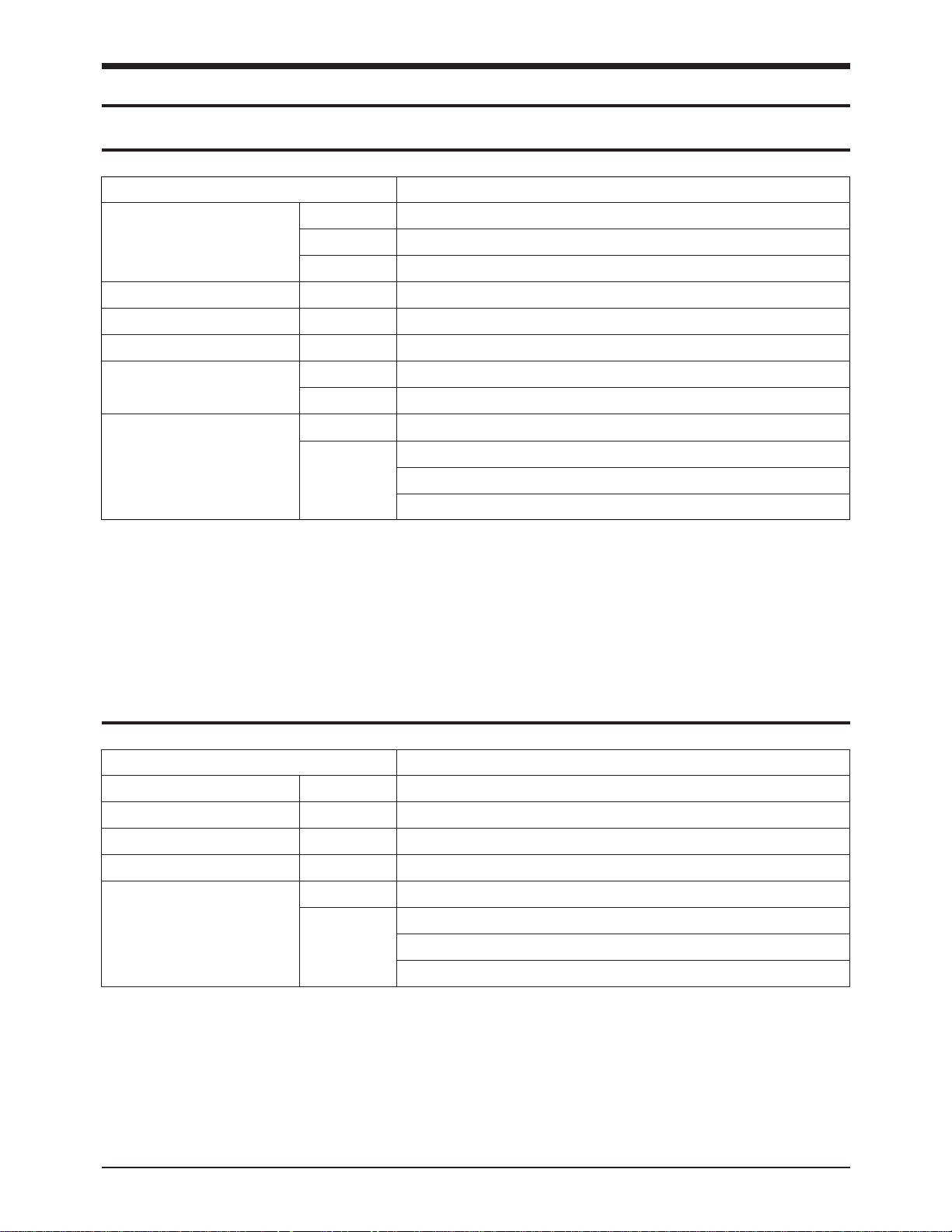
4-2 Main PBA and LIU PBA
Figure 4-2
1. Disconnect the handset cord modular plug
from the machine.
2. Remove the the six screws.
3. Remove the Main Chassis.
1. Loosen the six screws fastening the base.
2. Unplug the connector from the PBAs
3. Remove the MAIN PBA and LIU PBA.
Figure 4-1
Disassembly and Reassembly
4-2 SF700AT
4-3 Sensor PBA & Power
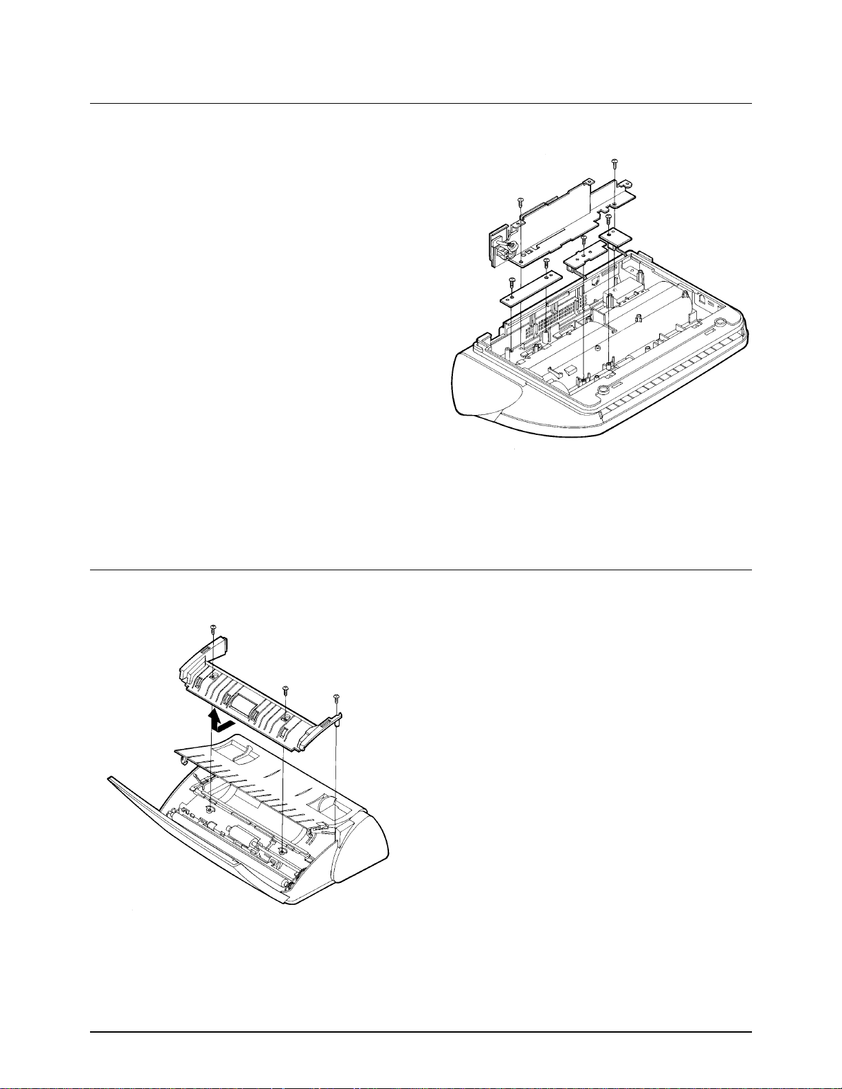
4-4 Top Cover
Figure 4-4
1. Loosen the six screws fastening the base.
2. Remove the Sensor PBA and Power.
1. Open the operation panel and RX-Cover.
2. Loosen the three screws fastening the top
cover.
3. Lift the top cover carefully.
Figure 4-3

Disassembly and Reassembly
SF700AT 4-3
4-5 Rear Cover
4-6 RX Cover
Figure 4-6
1. Loosen the four screws fastening the rear cover.
2. Remove the Rear Cover.
1. Hold the wire spring as shown in figure 4-6.
1. Remove the bushing.
3. Lift RX cover assembly, while pulling in the
direction of arrow.
Figure 4-5
Disassembly and Reassembly
4-4 SF700AT
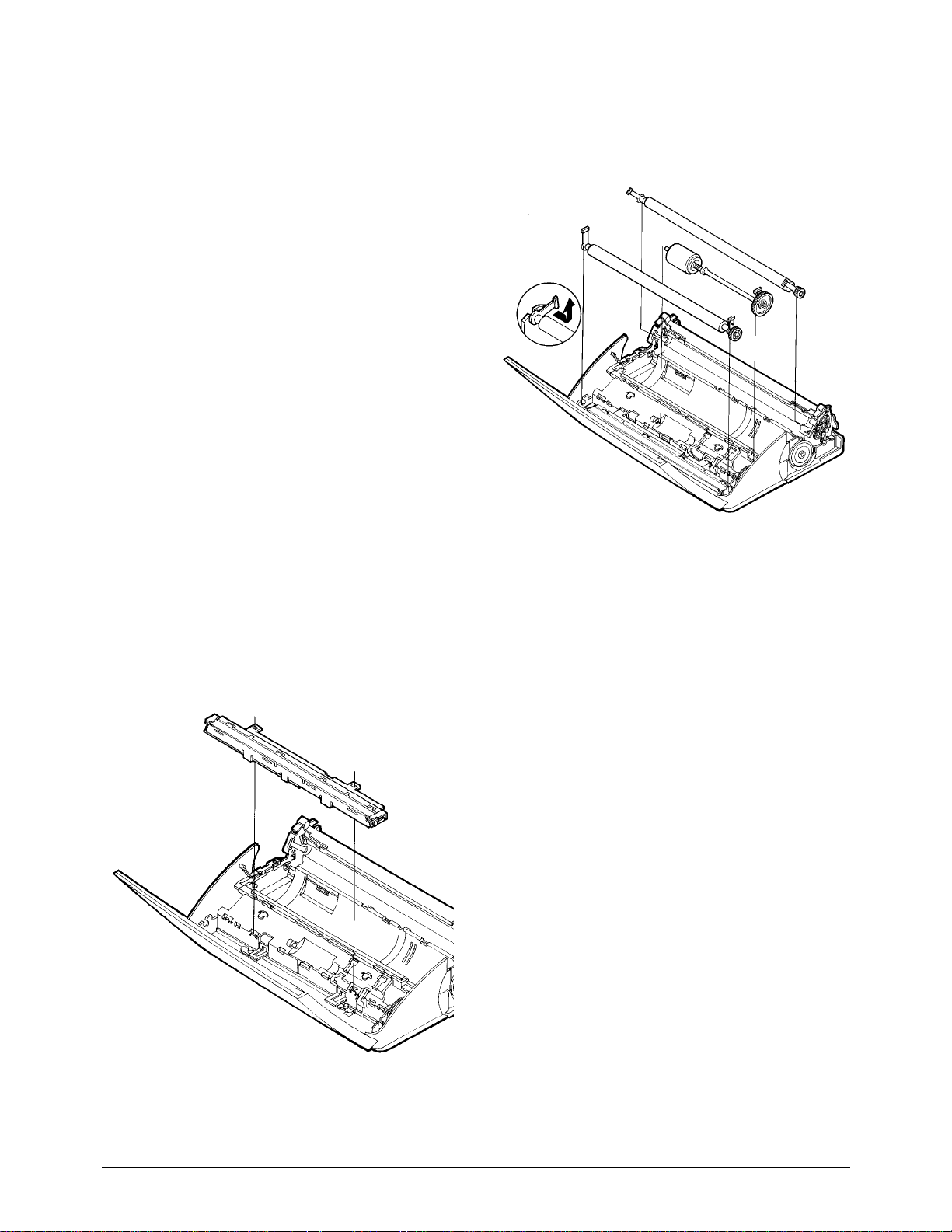
4-7 Rollers
4-8 CIS
Figure 4-8
1. Hold the bushing as shown in figure 4-7.
Remove the roller assembly from the bushing
with screwdriver.
2. Lift roller assembly, while pulling in the
direction of arrow.
1. Lift the CIS assembly.
2. Unplug the connector.
Figure 4-7
Disassembly and Reassembly
SF700AT 4-5
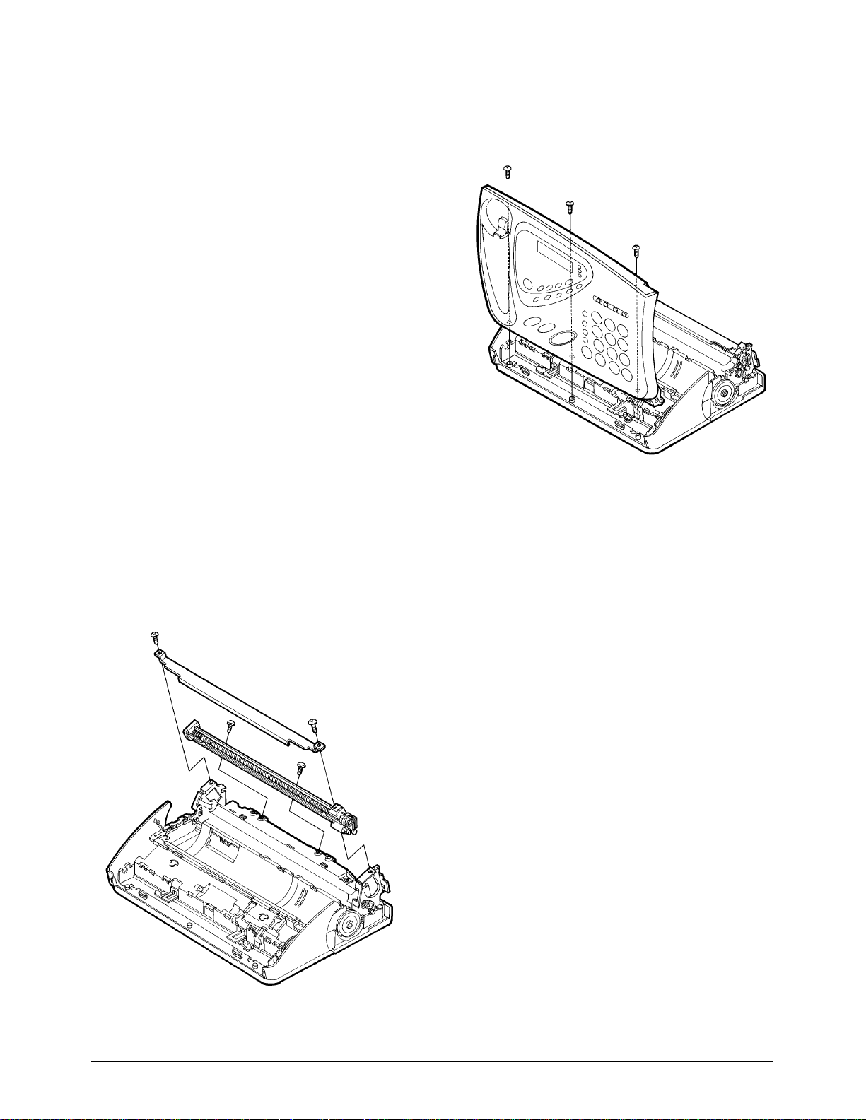
4-9 OPE Assembly
Figure 4-10
1. Loosen the three screws.
2. Lift the OPE assembly.
Figure 4-9
4-10 Cutter Assembly
1. Loosen the two screws fastening the Base.
2. Remove the cover cutter.
3. Loosen the two screws fastening the Base.
4. Lift the cutter.
Disassembly and Reassembly
4-6 SF700AT
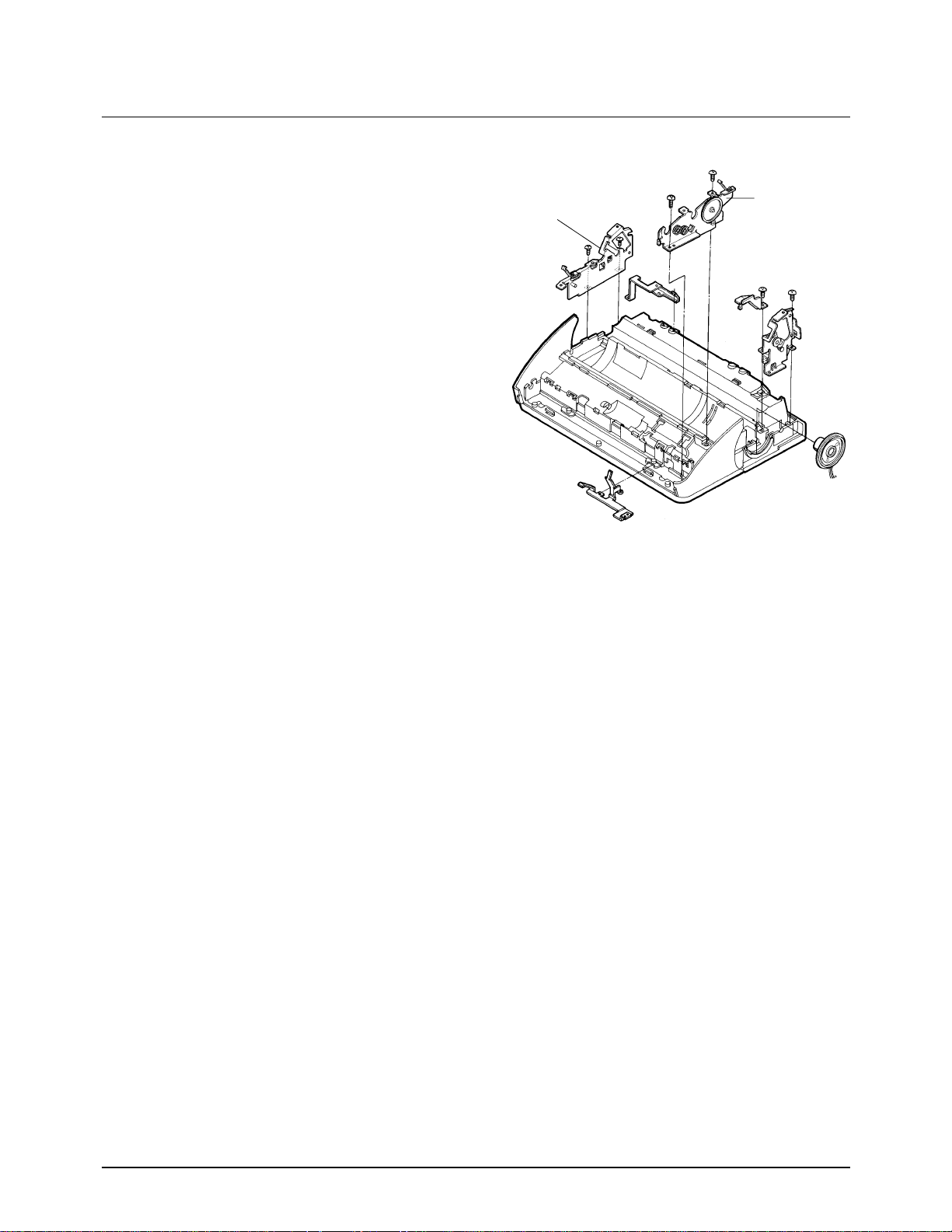
Figure 4-11
4-11 TX, RX Motor
1. Loosen the two screws fastening the Base.
(Rx motor assÕy)
2. Loosen the two screws fastening the Base.
(Tx motor assÕy)
TX Motor assÕy
RX Motor assÕy
SF700AT 5-1
5. Circuit Description
5-1 General
The main circuit board consists of memory, MODEM, TX- and RX-related circuitry, Speakerphone, TAD,
and the Integrated Facsimile Controller (IFC), which includes the CPU and I/O device drivers and controls
the system.
5-2 IFC
This circuit consists of the data and address bus, real time clock (RTC), image sensor, motor driver
controller, Thermal Print head controller, IFC including I/O port, and system reset circuit.
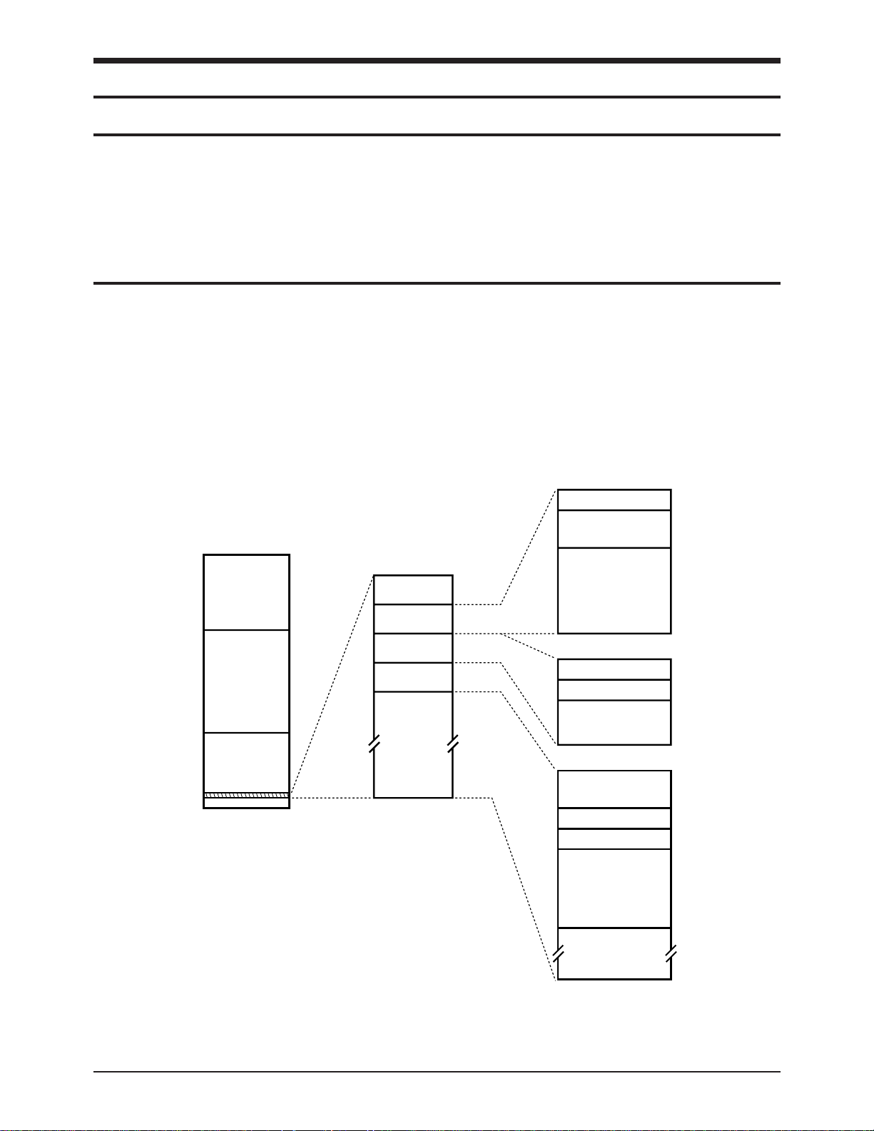
Figure 5-1: XFC-B Memory Map
CPU (Logical) Address Space
FFFFFF
F00000
0FFFFF
000000
MCSn
ROMCSn
CS0n
Not
Available
Internal
Registers
CS2n CS4n
CS1n
Internal
Memory
00FFFF
00FF00
00FE00
00FD00
00FC00
00E000
Reserved
Setup
Registers
Operational
Registers
CS4n
CS3n
CS2n
Reserved
Shading Inversion
DBCMC Buffer
Dither Table
Reserved
00FEFF
00FEE0
00FE80
00FE00
00FDFF
00FDC0
00FD80
00FD00
00FBFF
00FBE0
00FBD0
00FBC0
00FB80
00E000
5-2-1 Memory Map
The external memory of the CPU is divided into
32kB RAM (0000H through 8000H) and 64kB ROM
(FF0000H through FFFFFFH).
Circuit Description
5-2 SF700AT
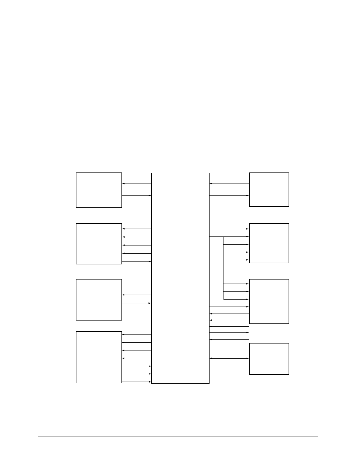
Figure 5-2: XFC-B Hardware Interface Signals
5-2-2 Data & Address Bus Control
/RD and /WR signals are active in the low state,
with the PH2 clock in a high state, and an internal
wait state occurs in the TSTCLK (6 MHz). These
signals are sent to the /RD and /WR ports of
RAM , ROM, and the MODEM in order to read or
write data when a chip select line is active.
/CS0: RAM chip select active (low)
/ROMCS: ROM chip select active (low)
/MCS: MODEM chip select active (low)
D0 - D7: 8 bit data bus
A0 - A16: address bus
5-2-3 System Clock
The 6 MHz internal clock frequency is generated
by dividing the 12 MHz system clock from
MODEM by two inside the MODEM.
OPERATOR
PANEL
SERIAL
COMMUNICATION
PRINTER
DATA
CONTROL
AND
SENSORS
MOTOR
DRIVER
(MOTOR)
SCANNER
CONTROL
AND
PROCESSING
RTC
CRYSTAL
EXTERNAL
BUS
MODEM
GENERAL
PURPOSE
I/ 0
TXD
RXD
STB 0~3
PDAT
PCLK
PLAT
THADI
SM 0~3
MOTOR POS
START
SCLK
VIDCTL1
H/B
Vin
+Vref
-Vref
XIN
XOUT
/ROMCS
/RAMCS
/RD/WR
D0~D7
A0~A16
/RD/WR
D0~D7
A0~A4
/MCS
/MIRQ
SYSCLK
/PWRDWN
/RESET
/BATRST
IFC(XFC-B)
 Loading...