

SAMSUNG FAXF5800IXEU Service Manual
SERVICE
SAMSUNG FACSIMILE
Msys 5150/5200
SF-5800/5800P
FACSIMILE CONTENTS
1. Precautions
2. Specification
3. Setup and Installing
4. Theory of Operation
5. Circuit Description
6. Repair Information
7. Maintenance & Troubleshooting
8. Exploded Views and Parts List
9. Electrical Parts List
10. Block Diagram
11. Connection Diagram
12. Schematic Diagrams
MANUAL

©Samsung Electronics Co., Ltd. Mar. 1999
Printed in Korea
P/N. JC68-00097A Rev.1.00
ELECTRONICS

1. Precautions
Follow these safety, ESD, and servicing precautions to prevent personal injury and equipment damage.
1-1 Safety Precautions
1. Be sur e that all built-in pr otective devices are in
place. Restore any missing protective shields.
2. Make sur e ther e are no cabinet openings through
which people- particularly children- might insert
fingers or objects and contact dangerous voltages.
3. When re-installing chassis and assemblies, be
sure to r estor e all pr otective devices, including
control knobs and compartment covers.
4. Design Alteration Warning:
Never alter or add to the mechanical or electrical
design of this equipment, such as auxiliary
connectors, etc. Such alterations and
modifications will void the manufacture r’s
warranty.
5. Components, parts, and wiring that appear to
have overheated or are otherwise damaged
should be replaced with parts which meet the
original specifications. Always determine the
cause of damage or overheating, and correct any
potential hazards.
6. Observe the original lead dress, especially near
sharp edges, AC, and high voltage power
supplies. Always inspect for pinched, out-ofplace, or frayed wiring. Do not change the
spacing between components and the printed
circuit boar d .
7. P r oduct Safety Notice:
Some electrical and mechanical parts have special
safety-r elated characteristics which might not be
obvious from visual inspection. These safety
featur es and the protection they pr ovide could be
lost if a replacement component diff ers from the
original. This holds tr ue, even though the
r eplacement may be rated for higher voltage,
wattage, etc.
Components critical for safety are indicated in
the parts list with symbols . Use only
r eplacement components that have the same
ratings, especially for flame resistance and
dielectric specifications. A replacement part that
does not have the same safety characteristics as
the original may create shock, fir e, or other safety
hazard s.
Samsung Electronics 1-1

1-2 Samsung Electronics
Precautions
1-2 ESD Precautions
Certain semiconductor devices can be easily
damaged by static electricity. Such components are
commonly called “Electrostatically Sensitive (ES)
Devices”, or ESDs. Examples of typical ESDs are:
integrated cir cuits, some field ef fect transistors, and
semiconductor “chip” components.
The techniques outlined below should be followed
to help r educe the incidence of component damage
caused by static electricity.
CAUTION: Be sure no power is applied to the
chassis or circuit, and observe all other safety
precautions.
1. Immediately before handling a semiconductor
component or semiconductor-equipped assembly,
drain off any electr ostatic char ge on your body
by touching a known earth ground. Alternatively,
employ a commercially available wrist strap
device, which should be r emoved for your personal
safety r easons prior to applying power to the unit
under test.
2. After r emoving an electrical assembly equipped
with ESDs, place the assembly on a conductive
surface, such as aluminum or copper foil, or
conductive foam, to prevent electr ostatic char ge
buildup in the vicinity of the assembly.
3. Use only a grounded tip soldering iron to solder
or desolder ESDs.
4. Use only an “anti-static” solder r emoval device.
Some solder removal devices not classified as
“anti-static” can generate electrical charges
s ufficient to damage ESDs.
5. Do not use Fr eon-propelled chemicals. When
sprayed, these can generate electrical charges
s ufficient to damage ESDs.
6. Do not remove a replacement ESD from it s
protective packaging until immediately before
installing it. Most r eplacement ESDs are
packaged with all leads shorted together by
conductive foam, aluminum foil, or a comparable
conductive material.
7. Immediately before removing the protective
shorting material from the leads of a r eplacement
ESD, touch the protective material to the chassis
or cir cuit assembly into which the device will be
installed.
8. Maintain continuous electrical contact between
the ESD and the assembly into which it will be
installed, until completely plugged or soldered
into the cir cuit.
9. Minimize bodily motions when handling
unpackaged replacement ESDs. Normal motions,
such as the brushing together of clothing fabric
and lifting one’s foot fr om a carpeted floor, ca n
generate static electricity suf ficient to damage an
ESD.
1-3 Lithium Battery Precautions
1. Exercise caution when replacing a Lithium
battery. There could be a danger of explosion and
subsequent operator injury and/or equipment
damage if incorrectly installed.
2. Be sure to replace the battery with the same or
equivalent type recommended by the
manufacturer.
3. Lithium batteries contain toxic substances and
should not be opened, crushed, or burned for
disposal.

2. Specification
2-1 Facsimile
Machine type : Desk Top
Applicable line : Public Switched Telephone Network (PSTN) or behind PA B X
Compatibility : CCITT Group 3
Data coding : MH/MR/MMR
Modem speed : 14400/12000/9600/7200/4800/2400 bps
Transmission speed : Approx. 6 sec.
Ef fective scanning width : 8.3 inches (210 mm)
Ef fective printing width : 8.2 inches (208 mm : LTR)
Scanning method : Sheet-fed scanning using a Contact Image Sensor (CIS)
Memory : Msys 5150 1 MByte/Msys 5200 2 MByte
SF-5800 1 MByte/SF-5800P 2 MByte
Halftone : 64 levels
Printing speed : 8 PPM (Letter size)
Automatic document feeder : 30 pages (75g/m2)
Documents size : W idth : 148 to 216 mm
Length : 128 to 1500mm (Single Page)
279 to 297mm (Multi Pages)
W eight : 50 to 100 g/m2 (Single Page)
50 to 90 g/m2(20 Pages)
75 g/m2(30 Pages)
One-touch dial : 20 locations
LCD : 1 6 characters x 2 lines
2-2 SCANNER
Scanning Method : Sheet-fed scanning by CIS and feeding of the document by a
stepping motor
Resolution
Horizontal 11.8 lines/mm (300 dpi)
V ertical S TANDARD : 3.85 lines/mm (98 Lpi)
FINE : 7.7 lines/mm (196 Lpi)
SUPER FINE : 11.8 lines /mm (300 Lpi)
Photo Scale : 256 shades
Scanning period : STANDARD : 2.5 ms/line
FINE : 2.5 ms/line
SUPER FINE : 2.5 ms/line
Samsung Electronics 2-1

2-2 Samsung Electronics
2-3 Printer
Print Speed 8 PPM (A4 Size, 5% Charcter Pattern) At Copy Mode
Resolution 600 X 600 DPI
Sourc e of Light Laser Diode(LSU)
Print Method Non-impact Electrophotography, Laser Beam
Feed Method Multi-Purpose Feeder and Manual
Feed Reference Center Reference Loading
Paper Size Bin Type
Normal Paper : A4,Letter,Legal,B5,
Executive, A 5
Envelope : Normal Envelope
Length : 149 ~ 356mm
W idth : 100 ~ 216mm
Weight : For MPF, 6 0 ~ 90g/m
2
For Manual, 60 ~163g/m
2
Paper Capacity MPF : 150 Sheets (based on 75g/m2)
Manual Slot : 1 Sheet
Paper Stacker Capacity Face up : 100 Sheets (75g/m2,20 lb)
W arming up Time
First Printing Time Stand-By : 20 Sec
Power Save Mode : 30 Sec
Power Rating AC 110V ~127V ± 15% 50/60Hz ± 3Hz,
AC 220V ~ 240V ± 15% 50/60Hz ± 3Hz
Power Consumption Avr. 170Wh
Power Saving Consumption A vg. 13Wh Sleeping Mode
Certification & Compliance FCC,UL,CSA,CE,CB
Acoustic Noise Standby : Less than 36dB
Sleep Mode : Less than 29dB
Operating : Less than 50dB
Specification

Samsung Electronics 2-3
Specification
Reliability MTBJ : 2,000 Sheets(75g/m2)
MTBF : 50,000 Sheets
Toner Cartridge One-Cartridge type
Expected Life Span 50,000 Sheets
Operating Environment Temperature : 10 ~ 32°C
Humidity : 20 ~ 80%
Storage Environment Temperature : -20 ~ 40 °C
Humidity : 10 ~ 95%RH
W eight Net : Max. 9kg
Gross : Max. 14kg
External Dimension 355(W) X 415(D) x 238(H)mm (without Handset)
424(W) X 415(D) x 238(H)mm (with Handset)
Developer .Life Span : 5% Pattern,Min. 5,000 Sheets
.Developing : Non-magnetic
Contact Developing
.Charging : Conductive Roller Charging
.Density Adjustment : Dark, Medium
.Toner Supply Method : Exchanging
Toner Cartridge
.New Developer Checkable
.Transfer System : Pre-transfer By LED &
Conductive Roller Transfer
.Fusing System : Temperature & Pressur e
OZONE Emission : Max. 0.1 PPM(8 Hours)

2-4 Samsung Electronics
Specification
2-4 Quality
Conditions
Paper Normal Paper 75g/m
2
Environment Temperature : 20 ~ 25°C
Humidity : 40 ~ 60%
Print Quality
Image Density Min. 1.3
Min. 1.0(Temperature : 10 ~ 15°C)
Background Max. 0.2
Uniformity Max. 0.2(Including Continuous Print)
Fusing Min. 75% (All Black)
Start Position Top : x ± 4.23mm, Side : y ± 4 m m From Left
Skew To p : Max. ± 1.5mm/200mm
Side : Max. ± 2.0mm/250mm
Orthogonality ± 1.0mm
Horizontal Scan ± 0.6mm/208mm
(Bowed Line Skew : Pattern 1)
Special Paper Exception Image Density : Min 1.0 (Envelope)
Fusing : Min. 70% (All Black)
(Envelope/OHP/Postcard)
Paper Jam Less than 1/1,000(75g/m2Paper)
Paper Curl First : Less than 16mm (10 Sheets, 75g/m2Paper)
After Cooling : Less than 16mm (10 Sheets, 75g/m2Paper)
Reliability
Insulation Resistance Less than 10 MΩ (at DC 500V)
Dielectric Str ength AC 1000V (DC 1420V), 10mA
Ground Continuous Less than 0.1 Ω
Voltage DIP Rated Voltage ± 1 5 %
AC Impulse Noise AC 1000V 10, 100, 200, 400, 1000ns Rated Power
Leakage Curre n t Less than 3.5mA
Sur ge 6 KV, 500A
OZONE Emission Less than 0.1 ppm (8 Hours)
Top Cover Open Isolating the input power of the LSU,
High Voltage Part, and Fuser
Overcurr ent Pr otect Fuse inside the Engine Controller
Fusing System
Trouble Sensing .The temperature doesn’t rise to the specific
temperature in the specific time.
.The temperature i s too high.
Overheat Sensing 240 ~ 250°C ( The thermostat cuts off the Fuser
from the power.)
Thermistor Open Sensing : W ithout the initial
temperature change of the Fuser
Indicate the
Fuser error

2-5 SMPS (Switching Mode Power Supply)
Input (AC)
AC Input Voltage Eur opean American
Minimum 198V 90V
Typical 230V 120V
Maximum 264V 135V
Max. AC Input Curre nt 2.5Amps 3Amps
Max. Inrush Curre n t Ap-p (at 20°C)
Output (DC)
Line Regulation 24V ± 1 0%
12V ± 5 %
Road Regulation -12V ± 5 %
5V ± 5%
Ripple Noise 24V : Peak 500mV
12V : Peak 500mV
-12V : Peak 500mV
5V : Peak 300mV
Over Current Protect 24V : 2.7A ± 10% (by Circ uit)
5V : 3A ± 10% (by Circ uit)
Over Voltage Protect 24V : 33VDC
5V : 5.6VDC
Samsung Electronics 2-5
Specification

2-6 Samsung Electronics
Specification
Memo

3-20 Samsung Electronics
Setup and Installing
3-8 System Data Set-up
There are system data settings that are set by the user in the user -mode, and system data settings set by the
technician in the tech mode.
3-8-1 System Data Settings in User-
mode
The fax machine has various user-selectable
functions. These functions are usually selected
during the initial setup of the machine, and there
should be little need to change them there after .
Note : Befor e you begin, print out the system data
list to see the curr ent settings. To print the system
data list, pr ess Menu, and ‘ System Data’ on the
one-touch keypad.
1. Pr ess Menu, then press ‘System Data’ on the
one-touch keypad.
The LCD displays user-selectable options.
2. Scroll to the options by pr essing „ or
r epeatedly.
3. When the option you want appears in the
display, enter the number for the desired status.
You can use ˆ or ¤ button and pre ss Enter to
select the desir ed status.
3-8-2 User-Selectable Options
These instructions assume you’ve followed the steps
under ‘System Data Settings in User-mode’ and the
machine is asking if you want to change one of the
options listed here .
•Paper Size-Select the paper size you will use for
the r ecor ding paper.
Pr ess 1 for letter (L TR), 2 for A4, or 3 for legal
(LGL) size paper.
•Message Confirmation Report-A confirmation
r eport shows whether the transmission was
successful or not, how many pages were sent, etc.
Press 1 to print out journal automatically each time
you send a fax.
Press 2 to print only when an error occurs and the
transmission was not successful.
•Auto Print Journal- A journal r eport shows specific
information concerning transmission and reception
activities, the time and dates up to 50 of the most
r ecent transmission and r eception.
Press 1 to print journal automatically after every 50
transmission and receptions.
Press 2 to print journal manually.
•Remote Receive Start Code-The remote receive
code allows you to initiate fax receive fr o m an
extension phone plugged into the EXT.TEL j ack. If
you pick up the extension phone and hear fax
tones, enter the r emote r eceive code and the fax
will start r eceiving. The password i s preset to
* 9 * at factory.
Enter the desired code 0 to 9 on the number
keypad.

Samsung Electronics 3-21
Setup and Installing
• Power Saving Mode (SF-5800P only) -The power
saving menu item lets you reduce power usage
when the printer is idle.
Pr ess 1 to turn the featur e ON. The display asks
you to determine the length of time the printer
waits after a job is printed before it goes to a
r educed power state:
Press 1 for 10 minutes, 2 for 15 minutes, 3 for 30
minutes, 4 for 45 minutes, or 5 for 60 minutes.
If your printer is used constantly, press 2 to turn
the feature OFF. It keeps the printer ready to print
with the minimum warm-up time.
• ECM Mode (Error Correction Mode)-This mode
compensates for poor line quality and ensure s
accurate, err or-free transmission with any other
ECM-equipped facsimile machine. If the line
quality is poor, transmission time may be
incr eased when ECM is enabled.
Pr ess 1 to turn the Err or Corr ection mode on.
Pr ess 2 to turn the Err or Corr ection mode off.
• RX Reduction-When receiving a document as
long as or longer than the paper installed in your
machine, the machine can reduce the data in the
document to fit into your recor ding paper size.
Turn on this featur e if you want to r educe an
incoming page that may otherwise need to be
divided into two pages with only a few
centimeters on the second page. If the fax machine
cannot reduce the data to fit into one page with
the feature enabled, the data is divided and
printed in actual size on two or more sheets if
needed.
Pr ess 1 to turn this featur e on. Note that this
feature does not apply to the copy mode.
Pr ess 2 to turn this featur e off. The overflow data
will be printed out on a second page.
• H.(Horizontal) Reduction-If you turn the RX
reduction feature on, you ar e allowed to set the
horizontal reduction feature on or off. When you
set the horizontal r eduction to be on, the machine
will r educe an incoming page containing overflow
data only in vertical as shown below.
If you want to reduce both in vertical and horizontal
at the same rate in order to maintain height to width
relationships, turn the horizontal reduction feature
of f. If you turn of f this featur e, the machine r educes
the data as shown below.
Pr ess 1 to turn this featur e on.
Pr ess 2 to turn this featur e off.
• Discard Size- When receiving or copying a
document as long as or longer than the paper
installed in your fax machine, you can set the fax
machine to discard any excess image at the
bottom of the page to fit into the r ecording paper
size.
If the received page is outside the margin you set,
it will be printed on two sheets of paper at the
actual size.
If the data is within the margin, and the Auto
Reduction feature i s turned on, it will be r educed
to fit into the appr opriate size paper (Discard does
not take place). If the Auto Reduction feature is
turned OFF or fails, the data within the margin
will be discarded.
Enter the desired discar d size using the number
keypad, and press Enter.

3-22 Samsung Electronics
Setup and Installing
• Redial interval- Y our machine can automatically
redial a r emote fax machine if it was busy or does
not answer the first call.
Enter the number of minutes (from 01 to 15) using
the number keypad.
• Redials- Enter the number of attempts (from 0 to
9) to redial the number before giving up.
If you enter 0, the machine will not redial.
• Answer Rings-You can select the number of times
your machine rings before answering an incoming
call. If you ar e using your machine as both a
telephone and a fax machine, we suggest you set
the ring count to at least 4 to give you time to
answer.
Enter a number from 1 through 7 on the number
keypad.
• DRPD (Distinctive Ring Pattern Detection)
Mode-’Distinctive Ring’ is a telephone company
service which enables a user to use a single
telephone line to answer several diff er ent
telephone numbers. The particular number
someone uses to call you on is identified by
different ringing patterns, which consist of various
combinations of long and short ringing sounds.
This feature is often used by answering services
who answer telephones for many differ ent clients
and need to know which number someone is
calling in on to pr operly answer the phone.
Using the Distinctive Ring Pattern Detection
feature, your fax machine can ‘learn’ the ring
pattern you designate to be answered b y the FA X
machine. Unless you change it, this ringing
pattern will continue to be recognized and
answered a s a FAX call, and all other ringing
patterns will be forwarded to the extension
telephone or answering machine plugged into the
E X T.LINE jack.
You can easily suspend or change Distinctive Ring
Pattern Detection at any time.
Before using the Distinctive Ring Pattern
Detection option, Distinctive Ring service must be
installed on your telephone line by the telephone
company. To setup Distinctive Ring Pattern
Detection, you will need another telephone line at
your location, or someone available to dial your
FAX number from outside.
Pr ess 1 to turn this featur e on.
Pr ess 2 to turn this featur e off.
Press 3 to setup the Distinctive Ring Pattern
Detection. The LCD displays ‘WAITING RING’.
Call your fax number from another telephone. It is
not necessary to place the call from a fax machine.
When your machine begins to ring, do not answer
the call. The machine requir es several rings to
learn the pattern.
When the machine completes ‘learning’, the LCD
displays ‘END DRPD SETUP’.
W ith the DRPD feature active, ‘DRPD’ appears in
the display and the previously set r eception mode
is ignor ed. If you turn DRPD off, the machine
returns to any previously set reception mode.
Notes:
• DRPD must be set up again if you r e-assign
your fax number, or connect the machine to
another telephone line.
• After DRPD has been set up, call your fax
number again to verify that the machine
answers with a fax tone, then have a call placed
to a dif ferent number assigned to that same line
to be sur e the call is forwar ded to the extension
telephone or answering machine plugged into
the EXT.LINE jack.
• Send from Memory-If you ar e annoyed that you
have to wait until documents in the feeder are
sent out when you try to send or reserve another
fax, turn this featur e on. This featur e enables all
transmission documents are automatically
scanned into memory before transmission.
Pr ess 1 to turn this featur e on.
Pr ess 2 to turn this featur e off.

Samsung Electronics 3-23
Setup and Installing
• Local ID- This feature allows the machine to
automatically print the page number, and the date
and time of the reception at the bottom of each
page of a received document.
Pr ess 1 to turn this featur e on.
Pr ess 2 to turn this featur e off.
• Priority T erm (Msys 5150/5200, SF-5800P) -When
you want to print a PC document while the
machine prints a received fax on the r ecording
paper, you can interrupt the printing and print the
PC document. Press the PRINT PRIORITY button
to enable the feature. The LCD displays ‘PP’ on
the lower line, right corner. The interrupted fax
data will be stor ed in memory. To disable, pr ess
the PRINT PRIORITY button again. ‘PP’ on the
LCD disappears.
You can set your machine to turn the feature off
automatically if there is no further data printed
within 30 minutes or 8 hours after PC printing.
Press 1 to select 8 hours. The machine turns off
automatically 8 hours after PC printing is
completed.
Press 2 to select 30 minutes. The machine turns off
automacally 30 minutes after PC Printing is
completed.
• Dial Mode (SF-5800/5800P Tech mode) -Select the
type of dial system your fax machine is connected
to.
Press 1 if the fax machine is connected to a tone
(Touch Tone) dial line.
Press 2 if the fax machine is connected to a pulse
(Rotary) dial line.
3-8-3 Confiming System Data Settings
Confirm the system data settings by printing out a
system data list.
1. If not in the tech mode, pr ess Menu, #, 1, 9, 3, 4
in sequence to initiate the tech mode.
2. Press Menu.
3. Press one of the one-touch PRINT keys. The LCD
displays the lists you can print out.
4. Pr ess „ or until you find ‘SYSTEM DATA
LIST’.
5. Pr ess Enter. The machine prints the system data
list.
The system data list printed in the tech mode
contains the system data set in the tech mode as
well as in the user mode. The model number and
software version will be printed at the bottom of
the system data list

3-24 Samsung Electronics
Setup and Installing
FEATURE PARAMETER FUNCTION
Modem Speed 14400/12000
9600/7200
4800/2400 bps
The maximum Tx speed can be limited to 14400, 12000, 9600, 7200, 4800 or
2400 bits per second. When the Tx speed is set to 14400, 12000 the Rx speed
can be either V.33 or V.17 speed. When the Tx speed is set to 9600 or 7200,
the Rx speed can be either V.29 or V.27ter speed. When the Tx speed is set
to 4800 or 2400, the Rx speed can be any V.27ter speed.
Error Rate 5%, 10% If the error rate exceeds the chosen rate, fall back occurs which will lower
the baud rate automatically down to as low as 2400 baud until the erro r
rate is less than the chosen rate.
3-8-4 System Data Settings in Tech-
mode
V arious technical featur es of fax machine ar e
provided with optional parameters. Set the feature s
to the user ’s need according to the following
p rocedure.
1. If not in the tech mode, pr ess Menu, #, 1, 9, 3, 4
in sequence to initiate the tech mode.
2. Pr ess Menu, and press ‘System Data’ on the
one-touch keypad.
The LCD displays ‘TECH MODE SYSTEM
D AT A?’.
3. To set the system data available in tech mode,
pr ess Enter.
If you want to set the system data available in the
user mode, pre ss Stop. The LCD displays ‘USER
MODE SYSTEM DATA?’. Pr ess Enter to set the
system data available in the user mode.
4. The LCD displays the options you can choose. In
tech mode, the LCD displays the technicianselectable options as well as all the userselectable options.
5. Scroll to the options by pr essing „ or
r epeatedly.
6. When the option you want appears in the
display, enter the number for the desired status.
You can use ‹ or ¤ button and pre ss Enter to
select the desir ed status.
Y ou can exit fr om setup mode at any time by
pr essing Stop. When you pre ss Stop, the
machine stores the options you’ve already
changed and returns to Standby mode.
Tx Level -4 ~ -15 dBm You can set the level of transmission signal. Typically, Tx level should be
under -12 dBm. The level within the range of -4 dBm to -15 dBm is
acceptable. Enter the desired value using the dial keypad.
Receive
Sensitivity
High/Normal High sensitivity is between -5 and -49 dBm. Normal sensitivity is -43 dBm.
Super Fine Scan
to Memory
200/300 dpi This feature allows the machine to scan documents in super fine resolution
(200 x 400 dpi, 300 x 300 dpi). The other machine can receive super fine
image. If the r emote machine is not capable of r eceiving super fine data, your
machine fails to send documents and displays ‘INCOMPABLE ERROR’.
Silence Time 12sec/Unlimit

Samsung Electronics 3-25
Setup and Installing
3-9 LCD Display
3-9-1 During Communication
In user mode, the LCD shows the remote machine’s
TTI number, TX or RX communication type,
(modem speed), and page number.
In service mode, the display shows the
communication type, abbreviations for the CCITT
Group 3 T.30 pr otocol as they occur, the pr otocol
type (G3), baud rate in kbps, and line time.
3-9-2 If a Communication Problem
Occurs:
In user mode, the display shows one of the
following:
PAPER JAM, COMM.ERROR, LINE ERROR.
In service mode, the display shows all error
messages available in user mode, as plus additional
error messages available only in Service Mode.
Er ror messages shown in service mode only are a s
follows:
PRE-MESSAGE ERROR : problem occurred during
phase B of session.
POST-MESSAGE ERROR : problem occurred during
phase D of session.
MESSAGE ERROR : problem occurred during phase
C of session.
LINE ERROR : machine cannot connect or has lost
connection with the remote machine.
Additional messages, not shown above, will appear
in the TX/RX journal printed in service mode.

3-26 Samsung Electronics
Setup and Installing
Memo
3. Setup and Installing
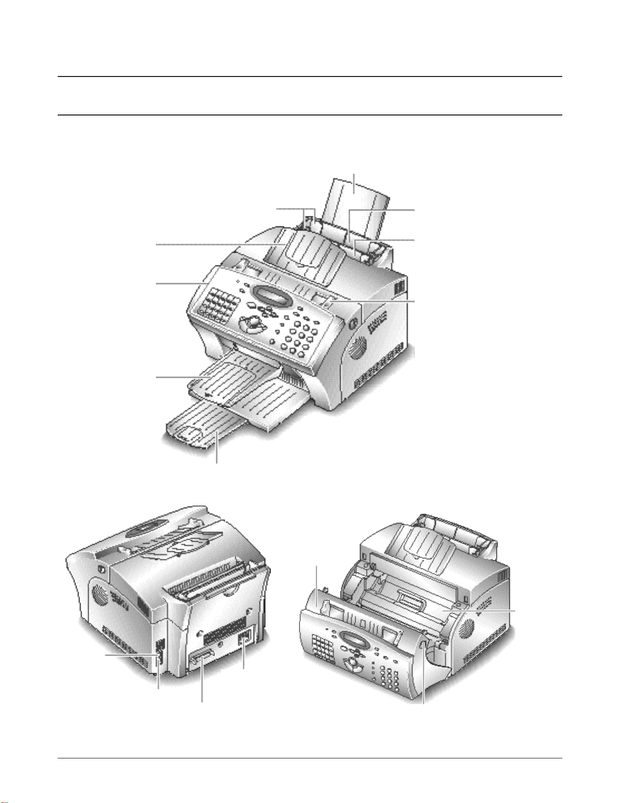
3-1 Control Locations and Functions
Take a moment to familiarize yourself with the main components and understand their functions.
3-1-1 Front View
Samsung Electronics 3-1
Paper Extension
Automatic Paper Feeder
Manual Paper Feeder
Document Guides
Paper Guides
Document Tray
Contro l Panel
Document Exit Tra y
Print Exit Tray
Note: Your machine may look slightly
different than the illustration.
Image
Cartridge
Cover
Cover Release Buttons
(right and left)
3-2-3 Inside
3-1-2 Rear View
Printer
Connector
Power Cord
Connector
TEL LINE
Jack
E X T. LINE Jack
3-2 Samsung Electronics
Setup and Installing
01
System Data System ID Date & Time System Setup Memory Clear
02 03 04 05
06 07 08 09 10
Delay TX Memory TX Priority TX Polling
11 12 13 14 15
Add/Cancel Group Dial Maintenance Journal Help List
16 17 18 19 20
TX Confirm Schedule Job Phone Book System List
Print Priority
On/Off Line
Volume
Stop
Multifunction LASER Facs
Menu
Copy
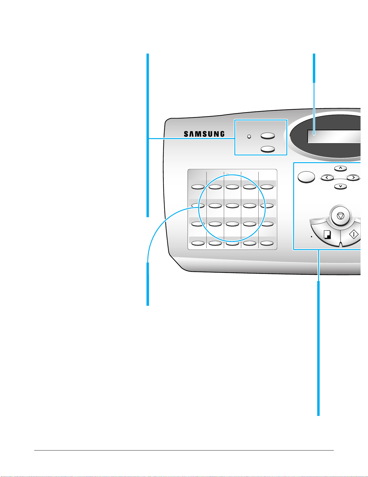
One-Touch Dial and
Special Function Buttons
Use to call most fr equently used
numbers with one button. Also, use
these buttons with Menu button to set
up special functions or print lists.
LCD Display
The display shows the current status of your
machine and guides you through various tasks
using a menu system for each of operation.
Up („ ) and Down ( )
Use to display the next or last menu item. Also,
use to adjust audible volume.
Menu
Use to choose special functions.
Left (ˆ ) and Right (¤ )
Use to move cursor left or right
t h rough the display.
Stop
Use to stop an operation at any time.
Copy
Use to copy a document.
Start/Enter
Use to start a job. Also use to activate the
selection shown in the display.
3-1-4 Using the Control Panel
On/Off Line and Lamp
Turn your machine On-line or Of f -line.
The lamp lights while the machine is
on-line, indicating the machine is ready
for printing a PC file.
Print Priority
Use to give print priority to PC file
while the machine prints
a r eceived fax.
Power Save
The power saving menu item lets you
r educe power usage when the printer is
idle.
Reset
Restores user -selectable options to the
default value.
Msys 5150/5200
SF-5800P
SF-5800
Samsung Electronics 3-3
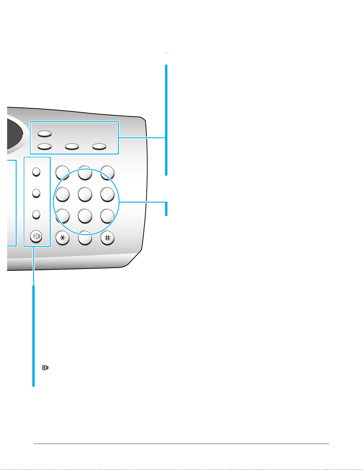
Setup and Installing
ABC
Rcv.Mode Resolution Contrast
Search/Delete
DEF
JKL MNO
TUV WXYZ
GHI
Redial/Pause
Speed/Status
Flash
OHD/V.Req.
PQRS
213
546
879
0
Search/Delete
Use to search for numbers in memory. O r use to delete
digits in the edit mode.
Rcv.Mode (Receive Mode)
Use to choose the receive mode you want to use.
The selected mode is displayed.
Resolution
Use to choose the resolution of copied or transmitted
documents.
Contrast
Use to choose the contrast of copied or transmitted
documents.
Speed/Status
Use to dial calls and send fax documents by entering a 2-digit number.
Also use to switch the LCD while performing dual jobs.
Redial/Pause
Use to redial the last phone number called. You can also use it to add a pause when storing a number in
memory.
Flash (R/Recall)
Use to perform a switch-hook operation such as call waiting.
O H D (On-Hook Dial) / V .Req. (Voice Request)
Use to dial numbers without picking up the handset. Also use it
to make a voice call after sending or receiving a fax.
Number Keypad
Use to dial numbers manually or to enter letters.
3-4 Samsung Electronics
Setup and Installing
3-2 Setting Up Your Machine
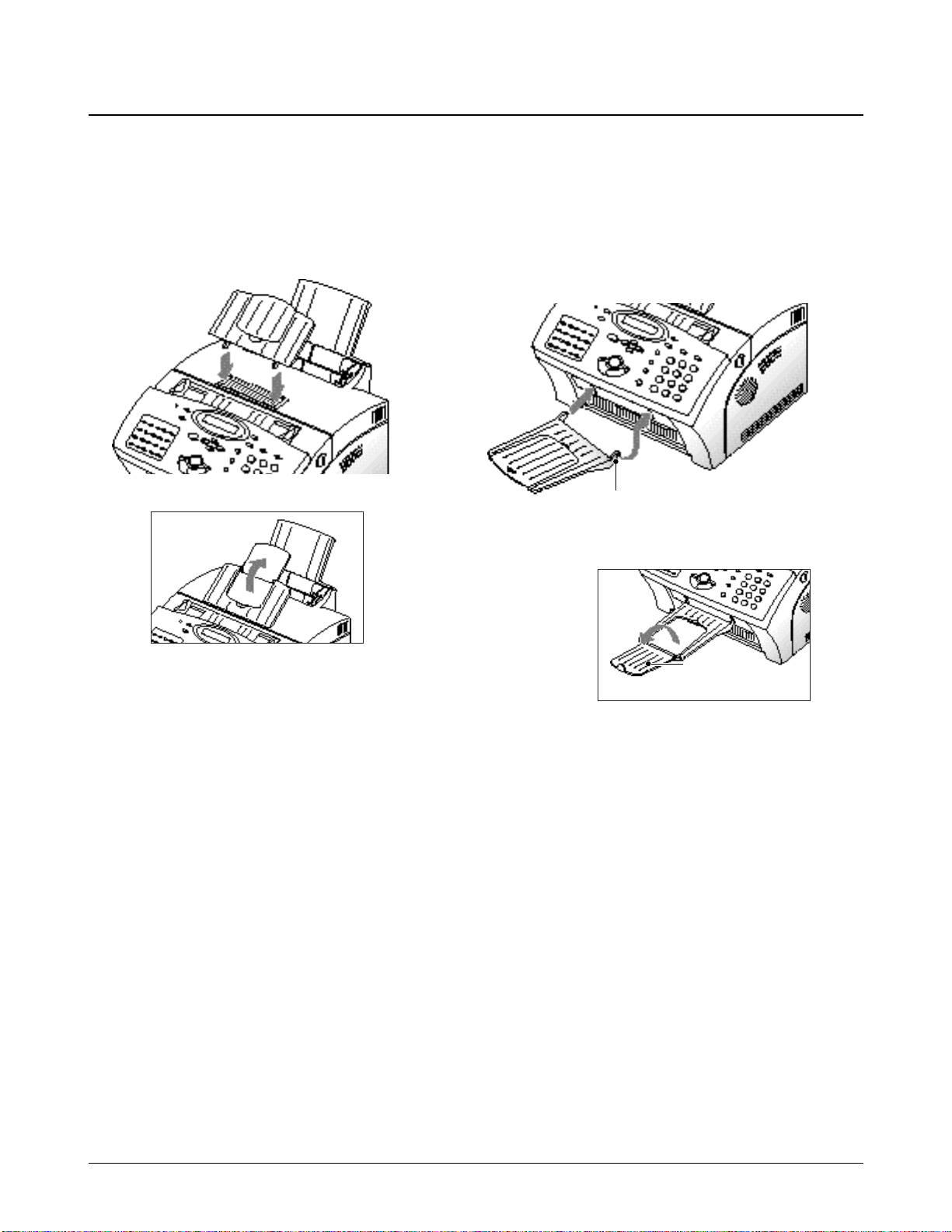
3-2-1 Document Tray
Insert two tabs on the tray into the slots as shown.
Fold out the extender on the tray, i f necessary.
3-2-2 Document Exit Tray
Insert the two tabs on the document exit tray into
the slots on the fr ont of your machine. Fold out the
extender, if necessary.
Extender
Insert one end first, then the other end by pulling
this leg inward to make the tray easy to insert.
Samsung Electronics 3-5
Setup and Installing
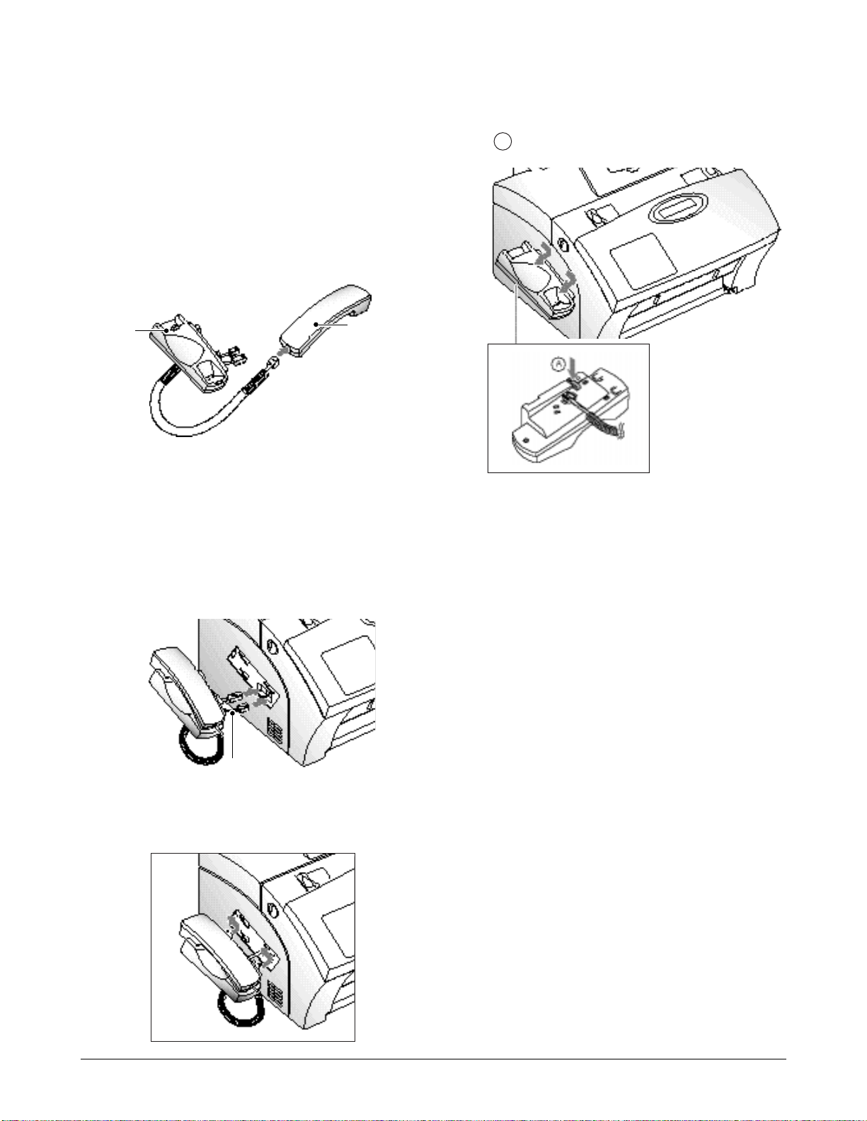
3-2-3 Handset and Handset Cradle
(only for SF-5800/5800P equipped with handset)
1. Plug one end of the coiled cord into the jack on
the handset. Then plug the other end into the
modular jack on the bottom of the handset
cradle.
2. Plug the cradle’s modular cor ds into the modular
jacks on the left side of your machine.
Attach the handset cradle to the main body.
Insert the thr ee tabs of the cradle into the slots on
the left side of the main body as shown, and
push it up.
Cradle
Handset
Black cor d
Route the excess cord so that it could be
inserted into the cradle.
Note: If you want to r emove the handset, pushing
in the bottom, slide it down, then take it out.
A
3-6 Samsung Electronics
Setup and Installing
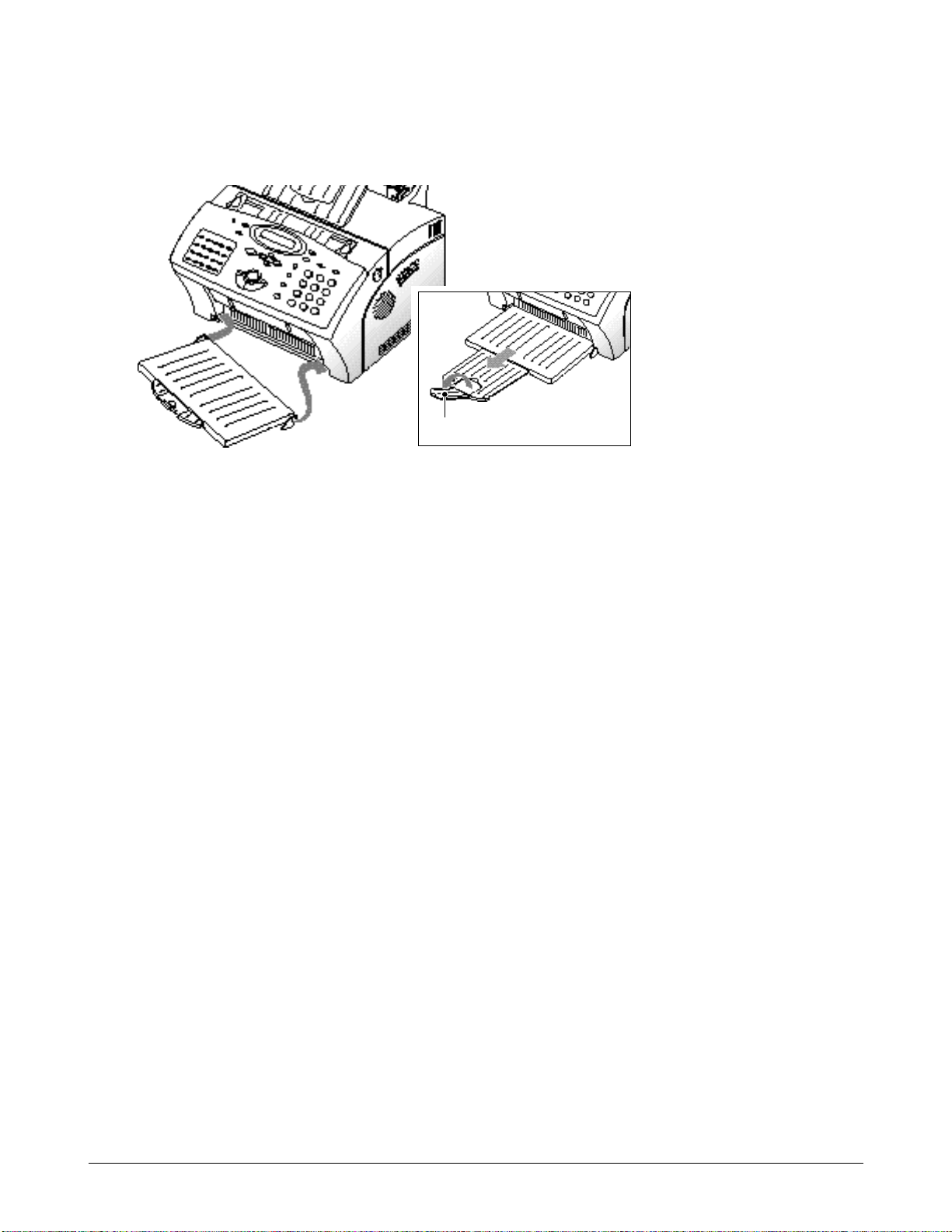
3-2-4 Printer Exit Tray
Holding the flexible side end, insert two tabs on the side ends into the corresponding slots. Fold out the
extender, if necessary.
Extender
Setup and Installing
Samsung Electronics 3-7
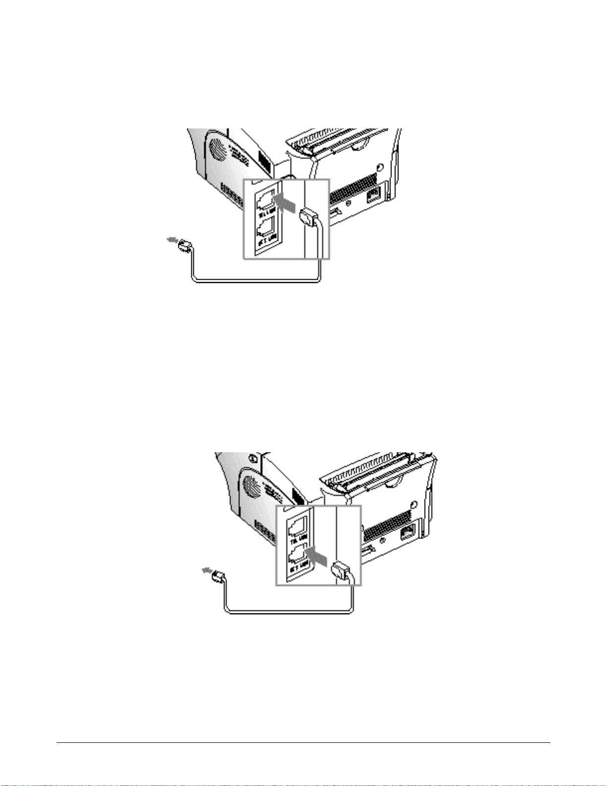
3-2-5 Telephone Line
Plug one end of the telephone line cord into the TEL LINE jack and the other end into a standard phone wall
jack.
Extension Phone
If you want to use a regular phone or answering machine with your machine, connect the phone into the
E X T.LINE jack.
Plug the cord of your extension phone or answering machine into the socket marked EXT.LINE on the back of
the machine.
To a standard
phone wall jack
To a regular phone
Setup and Installing
3-8 Samsung Electronics
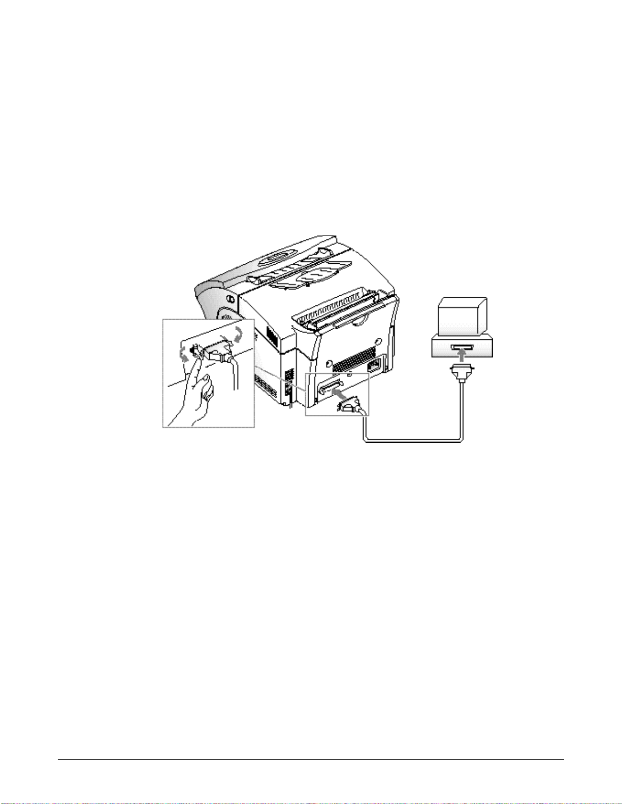
3-2-6 Printer Cable
Your Msys 5150/5200, SF-5800P has a parallel interface port, which allows you to use it with IBM PCs and
compatible computers. You have to purchase a Centronics parallel interface cable that supports bi-directional
communications (IEEE standard 1284). Ask your dealer for assistance if you need help selecting the right cable.
To connect the printer to the computer, follow the steps below:
1. Make sur e that both the Msys 5150/5200, SF-5800P and the computer are turned off.
2. Plug the cable into the connector on the back of the printer. Push the metal clips down to fit inside the
notches on the cable plug.
3. Connect the other end of the cable to the parallel interface port on your computer. See your computer
documentation if you need help.
Setup and Installing
Samsung Electronics 3-9
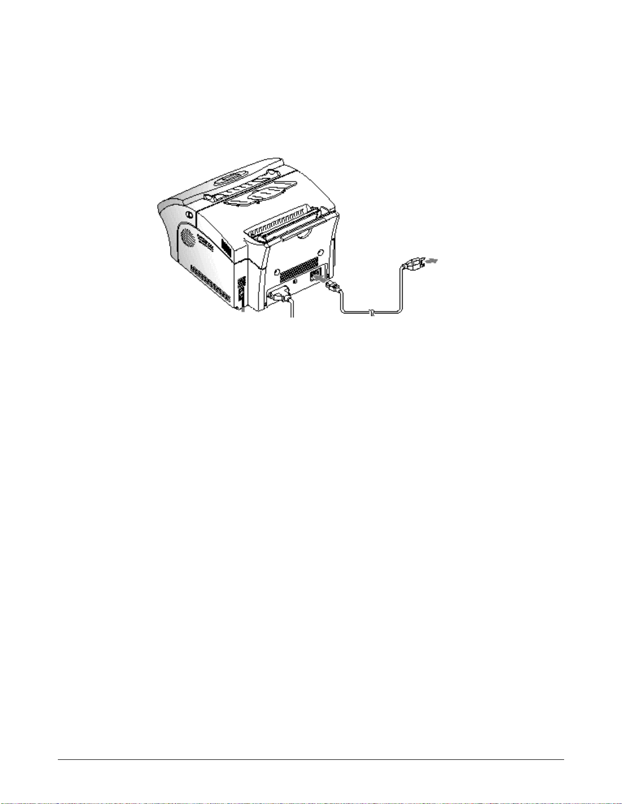
3-2-7 AC Power Cord
Plug one end of the cord into the back of the machine and the other end into a standard AC power outlet.
The machine turns on. If there is no cartridge installed, or no paper, the display shows ‘DOOR OPEN or NO
TONER!!!’ or [NO PAPER].
If you want to turn it off, unplug the power cor d .
To AC
outlet
Setup and Installing
3-10 Samsung Electronics
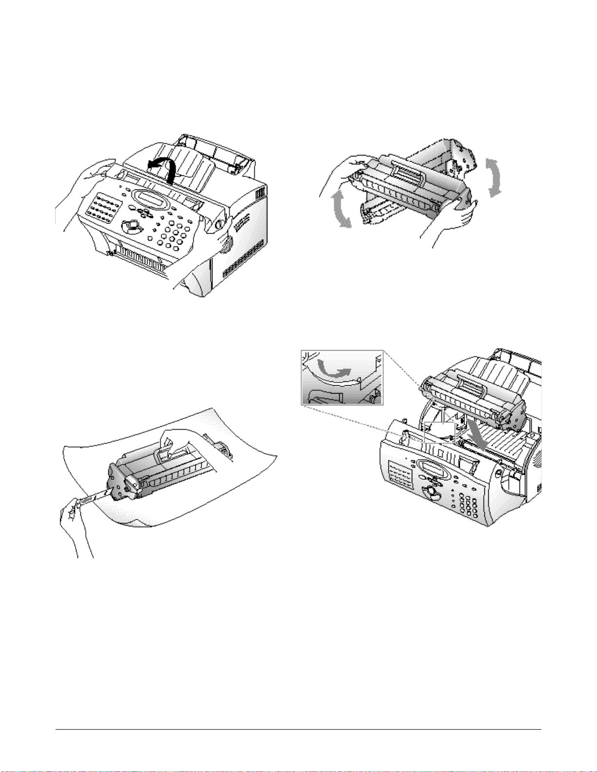
3-2-8 Installing the Image Cartridge
1. Pulling the cover r elease button towar d you,
open the cover.
2. Unpack the image cartridge, then car efully
r emove the sealing tape.
4. Find the cartridge slots inside the printer, one on
each side.
3. Shake the cartridge fr om side to side 5 or 6 times
to distribute the toner evenly inside the
cartridge.
Setup and Installing
Samsung Electronics 3-11
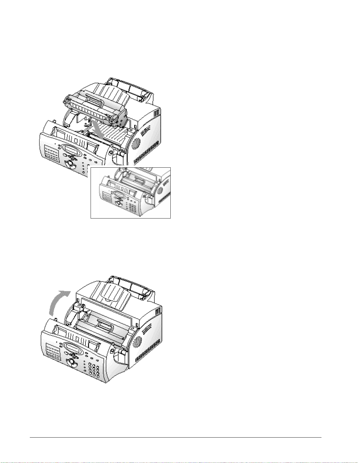
5. Grasp the handle and slide the cartridge down
between the cartridge slots, until it drops into
place.
6. Close the cover. Make sure that the cover is
securely closed.

Setup and Installing
3-12 Samsung Electronics
3-3 System Setup
I n Tech mode (press Menu # 1 9 3 4), you can access the following setup menu function :
•Ringer Volume
•Default settings
•Sound control
•Remote Diagnosis Protection
•Select Language
•Econo Mode Setting
•Page Count Clear
•Flash Download
To access system setup menu function.
1. Press Menu in tech mode.
2. Pr ess System setup on the one-touch keypad.
The first setup menu ‘RINGER VOLUME?’
appears in the display.
3. Pr ess „ or repeatedly to choose the desired
setup menu.
4. When the desired setup item is displayed, use ˆ
or ¤ to select the desired status, and press Enter.
To change the status, you can also press the
number of the status in the display.
5. The display shows the next setup menu. If you
r eturn to Standby mode, pre ss Stop.

Samsung Electronics 3-13
Setup and Installing
Function Description Value
Ringer Volume You can adjust the volume of the
ringer.
The display shows the loudness level with
> symbol. The more , the louder.
Default Setting
•Resolution
•Contrast
The print resolution and contrast can
be set to their most fr equently used
modes. Whenever a document is sent
or copied, the home contrast and
r esolution mode will be activated
unless otherwise changed by using
Resolution or Contrast button on the
control panel.
Home Resolution
•STANDARD–use with most documents.
•FINE–use for documents with fine detail,
such as small print.
•SUPER FINE–use for documents that
have extremely fine detail.
Home Contrast
•NORMAL–use with documents of
average or normal contrast.
•DARKEN–use with documents with low
contrast or light images.
•LIGHTEN–use with documents with
high contrast or dark images.
•PHOTO–for obtaining maximum image
quality with documents that
contain pictures or photographs
with shades of gray.
Sound Control
•Alarm Sound
•Key Sound
You can choose an alarm tone to
sound when an erro r occurs
(ALARM SOUND) or any key is
p ressed (KEY SOUND).
1: ON
2: OFF
Remote Diagnosis
Protection
Remote diagnosis feature allows
your machine to be checked out by
service company at a remote place
t h rough phone line.
If you do not want to use the remote
diagnosis feature and want to
protect your machine from being
open by an unauthorized person,
you can enable this remote
diagnosis protection featur e.
1: ON
2: OFF
Select Language You can select the LCD display
language between English, German,
etc.
1: English
2: German
 Loading...