

SAMSUNG FAXF3000I Service Manual
SERVICE
SAMSUNG FACSIMILE
SF3000/SF3000T
Manual
FACSIMILE CONTENTS
1. Precautions
2. Specifications
3. Installation
4. Service Mode
5. Circuit Description
6. Disassembly and Reassembly
7. Troubleshooting
8. Packing Assembly
9. Electrical Parts List
10. Block Diagram,
11. Connection Diagram
12. Schematic Diagrams

©Samsung Electronics Co., Ltd. Jul. 1998
Printed in Korea
P/N. JB68-60988A
ELECTRONICS

1. Precautions
Follow these safety, ESD, and servicing precautions to prevent personal injury and equipment damage.
1-1. Safety Precautions
1. Be sure that all built-in protective devices are in
place. Restore any missing protective shields.
2. Make sure there are no cabinet openings through
which people- particularly children- might insert
fingers or objects and contact dangerous voltages.
3. When re-installing chassis and assemblies, be
sure to restore all protective devices, including
control knobs and compartment covers.
4. Design Alteration Warning:
Never alter or add to the mechanical or electrical
design of this equipment, such as auxiliary
connectors, etc. Such alterations and
modifications will void the manufacturerÕs
warranty.
5. Components, parts, and wiring that appear to
have overheated or are otherwise damaged
should be replaced with parts which meet the
original specifications. Always determine the
cause of damage or overheating, and correct any
potential hazards.
6. Observe the original lead dress, especially near
sharp edges, AC, and high voltage power
supplies. Always inspect for pinched, out-ofplace, or frayed wiring. Do not change the
spacing between components and the printed
circuit board.
7. Product Safety Notice:
Some electrical and mechanical parts have special
safety-related characteristics which might not be
obvious from visual inspection. These safety
features and the protection they provide could be
lost if a replacement component differs from the
original. This holds true, even though the
replacement may be rated for higher voltage,
wattage, etc.
Components critical for safety are indicated in
the parts list with symbols . Use only
replacement components that have the same
ratings, especially for flame resistance and
dielectric specifications. A replacement part that
does not have the same safety characteristics as
the original may create shock, fire, or other safety
hazards.
Samsung Electronics 1-1

1-2 Samsung Electronics
Precautions
1-2. ESD Precautions
Certain semiconductor devices can be easily
damaged by static electricity. Such components are
commonly called ÒElectrostatically Sensitive (ES)
DevicesÓ, or ESDs. Examples of typical ESDs are:
integrated circuits, some field effect transistors, and
semiconductor ÒchipÓ components.
The techniques outlined below should be followed
to help reduce the incidence of component damage
caused by static electricity.
CAUTION: Be sure no power is applied to the
chassis or circuit, and observe all other safety
precautions.
1. Immediately before handling a semiconductor
component or semiconductor-equipped assembly,
drain off any electrostatic charge on your body
by touching a known earth ground. Alternatively,
employ a commercially available wrist strap
device, which should be removed for your personal
safety reasons prior to applying power to the unit
under test.
2. After removing an electrical assembly equipped
with ESDs, place the assembly on a conductive
surface, such as aluminum or copper foil, or
conductive foam, to prevent electrostatic charge
buildup in the vicinity of the assembly.
3. Use only a grounded tip soldering iron to solder
or desolder ESDs.
4. Use only an Òanti-staticÓ solder removal device.
Some solder removal devices not classified as
Òanti-staticÓ can generate electrical charges
sufficient to damage ESDs.
5. Do not use Freon-propelled chemicals. When
sprayed, these can generate electrical charges
sufficient to damage ESDs.
6. Do not remove a replacement ESD from its
protective packaging until immediately before
installing it. Most replacement ESDs are
packaged with all leads shorted together by
conductive foam, aluminum foil, or a comparable
conductive material.
7. Immediately before removing the protective
shorting material from the leads of a replacement
ESD, touch the protective material to the chassis
or circuit assembly into which the device will be
installed.
8. Maintain continuous electrical contact between
the ESD and the assembly into which it will be
installed, until completely plugged or soldered
into the circuit.
9. Minimize bodily motions when handling
unpackaged replacement ESDs. Normal motions,
such as the brushing together of clothing fabric
and lifting oneÕs foot from a carpeted floor, can
generate static electricity sufficient to damage an
ESD.
1-3. Lithium Battery Precautions
1. Exercise caution when replacing a Lithium
battery. There could be a danger of explosion and
subsequent operator injury and/or equipment
damage if incorrectly installed.
2. Be sure to replace the battery with the same or
equivalent type recommended by the
manufacturer.
3. Lithium batteries contain toxic substances and
should not be opened, crushed, or burned for
disposal.

2. Specification
GENERAL
Application Circuit : PSTN or behind PABX
Mode of Operation : Half-Duplex
Communication Mode : ITU Group 3
Effective Scanning Width : A4 (210 mm)
Scanning Method : CIS
Recording Paper Size : A4, Letter, Legal
Effective Recording Width : 8 inch (203.2 mm)
Recording Method : Thermal Ink-Jet
ADF : 15 sheets (based on A4 /20 lbs)
Paper Capacity : 100 sheets (based on A4, 10mm)
Resolution : Standard/Fine/Super Fine/Photo
Gray Scale : 64 levels
Contrast : Light/Auto/Dark
Memory : 512 kbyte for EPROM, 32 kbyte for SRAM
Modem Speed : Max. 14,400 bps
Coding Method : MH/MR/MMR
Transmission Speed : 10 seconds (Phase C by ITU 4% Chart/Memory TX)
Back Up Battery : 3 V Lithum / non-rechargeable
Power Supply : Check power label attached near the power cord connection.
Insulation Resistance : 50 Mohm or more (typ. 3 G at 500 V)
Dimension (W x D x H mm) : 384 x 330 x 183 mm (including ASF)
Samsung Electronics 2-1
2-2 Samsung Electronics
LIU
Out Band Signal Level :
0 - 4 kHz P-20 dBm or less
4 - 12 kHz P-40 dBm or less
2 kHz or more P-60 dBm or less
Input Level Range : -5 ~ -48 dBm
Coding Format
H
1209 Hz 1336 Hz 1477 Hz
L
697 Hz 1 2 3
770 Hz 4 5 6
852 Hz 7 8 9
941 Hz * 0 #
Frequency Tolerance : ± 1.5%
Specification
3. Installation
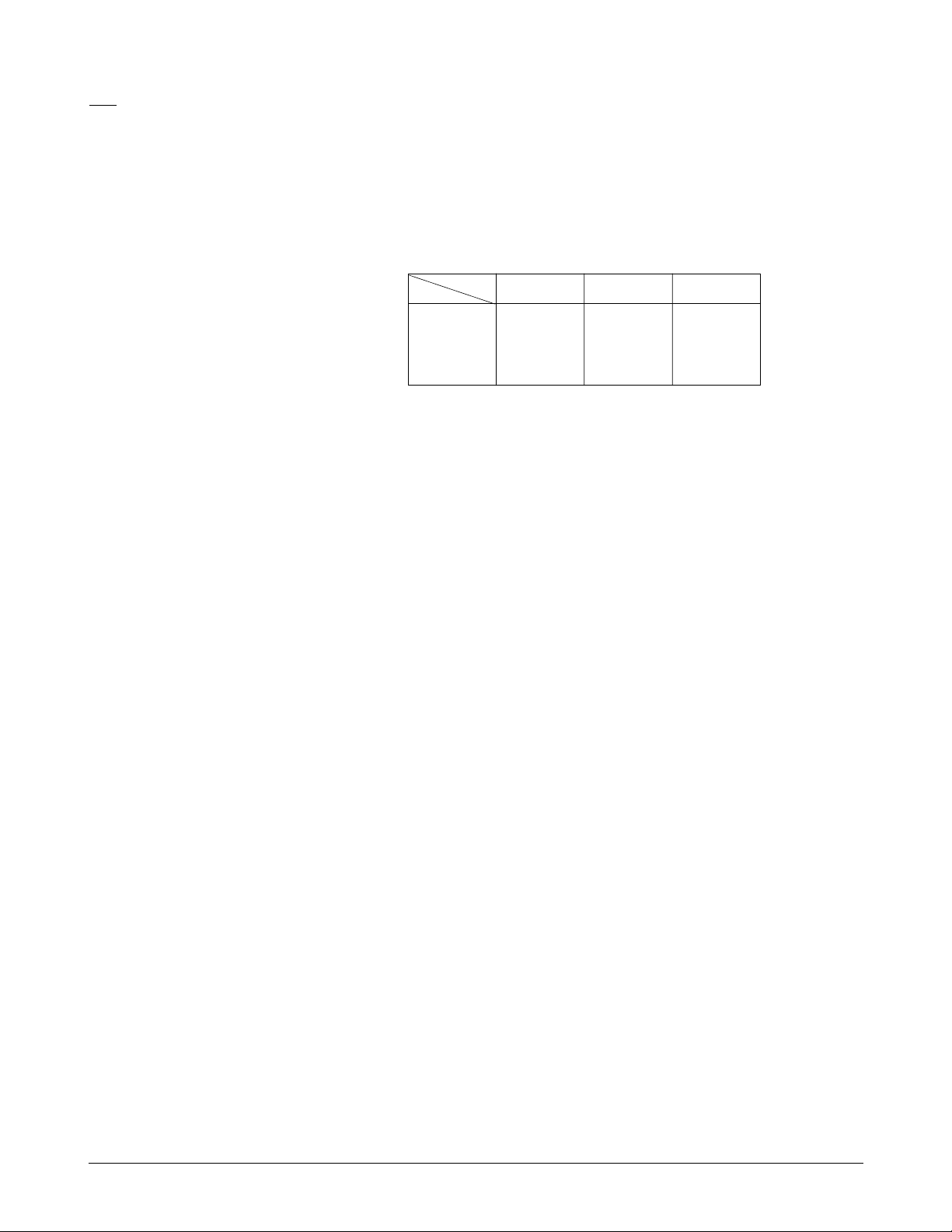
3-1. Connections
3-1-1. Connection Diagram 3-1-3. Document Tray
1. Insert the two tabs on the document tray into the
slot on top of your machine.
2. Fold out the extender on the document tray, if
necessary.
3-1-2. Handset
Plug one end of the coiled cord into the jack on the
handset, the other end into the modular jack on the
left side of the machine.
Samsung Electronics 3-1
0
0
0
0
0
0
0
0
0
0
0
0
0
0
0
0
0
0
0
0
0
0
0
0
0
0
0
0
0
0
0
0
0
0
0
0
0
0
0
0
0
0
0
0
0
0
0
0
0
0
0
Extension phone (option)
(for SF3000 only)
Phone line cord
AC power
cord
Handset
Extender
3-2 Samsung Electronics
Installation
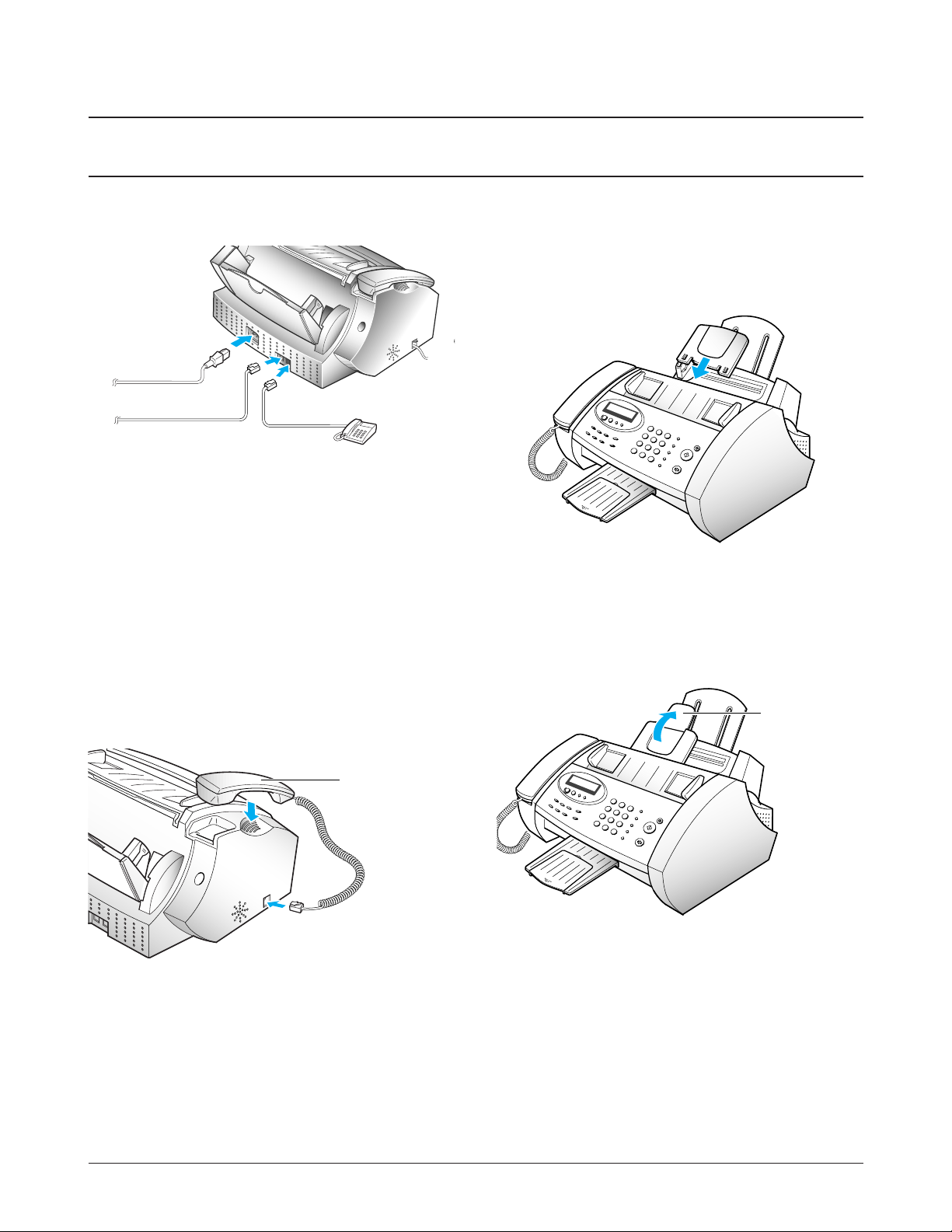
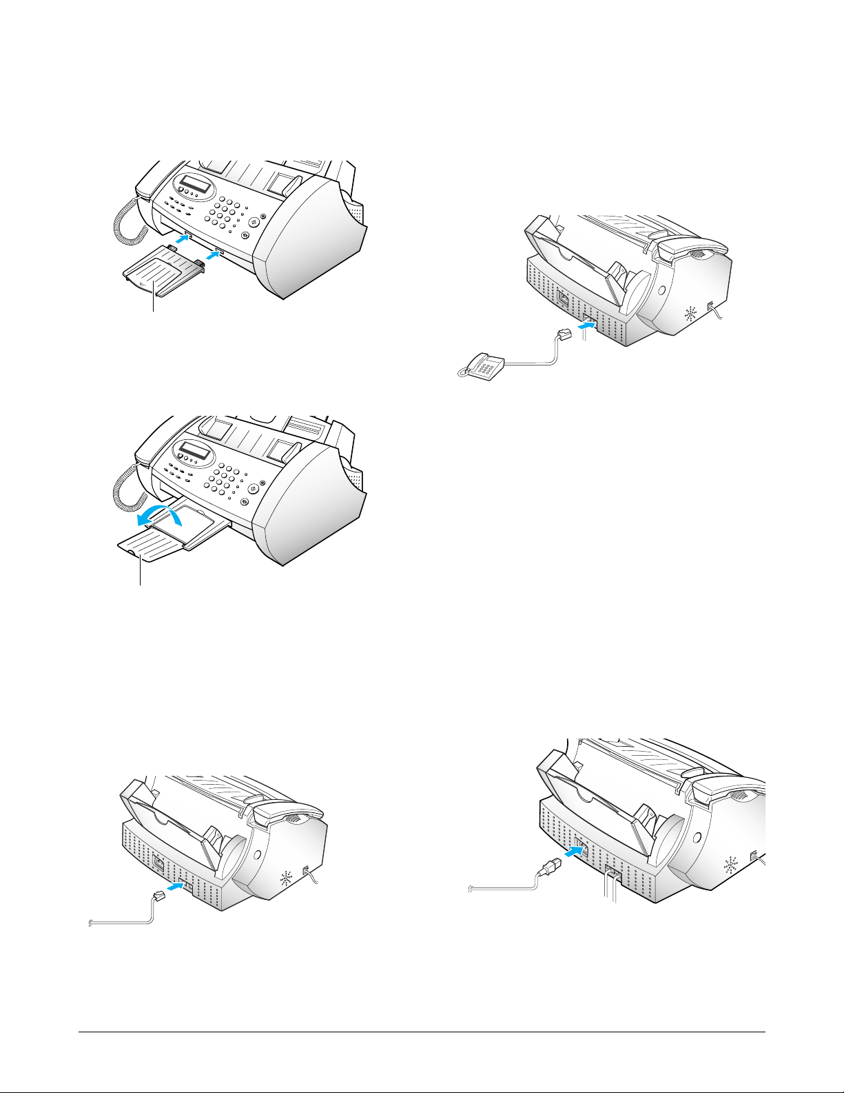
3-1-4 Document Exit Tray
1. Insert the two tabs on the document exit tray into
the slots on the front of your machine.
2. Fold out the extender, if necessary.
3-1-5. Telephone Line
Plug one end of the telephone line cord into the
TEL. LINE jack,the other end into a standard phone
wall jack.
3-1-6. Extension Phone (Optional)
(SF3000 only)
Plug one end of the cord of your extension phone
into the TAM lead and the plug of the TAM lead
into the socket marked EXT. LINE on the back of the
machine.
3-1-7. AC Power Cord
Plug one end of the cord into the back of the
machine, and the other into a standard, grounded 3pin AC socket (220 - 240 V, 50 - 60 Hz).
The machine turns on and the LCD displays
ÔSYSTEM INITIAL..Õ. If there is no cartrige installed,
or no paper, the display shows ÔNO CARTRIDGEÕ
or ÔPAPER EMPTYÕ.
To turn the machine off, unplug the power cord.
Note: If documents are deleted from memory due to
a power failure, the machine automatically prints
out a Power Failure report when power is reapplied.
0
0
0
0
0
0
0
0
0
0
0
0
0
0
0
0
0
0
0
0
0
0
0
0
0
0
0
0
0
0
0
0
0
0
0
0
0
0
0
0
0
0
0
0
0
0
0
0
0
0
0
0
0
0
0
0
0
0
0
0
0
0
0
0
0
0
0
0
0
0
0
0
0
0
0
0
0
0
0
0
0
0
0
0
0
0
0
0
0
0
0
0
0
0
0
0
0
0
0
0
0
0
Extender
Document exit tray

Samsung Electronics 3-3
Installation
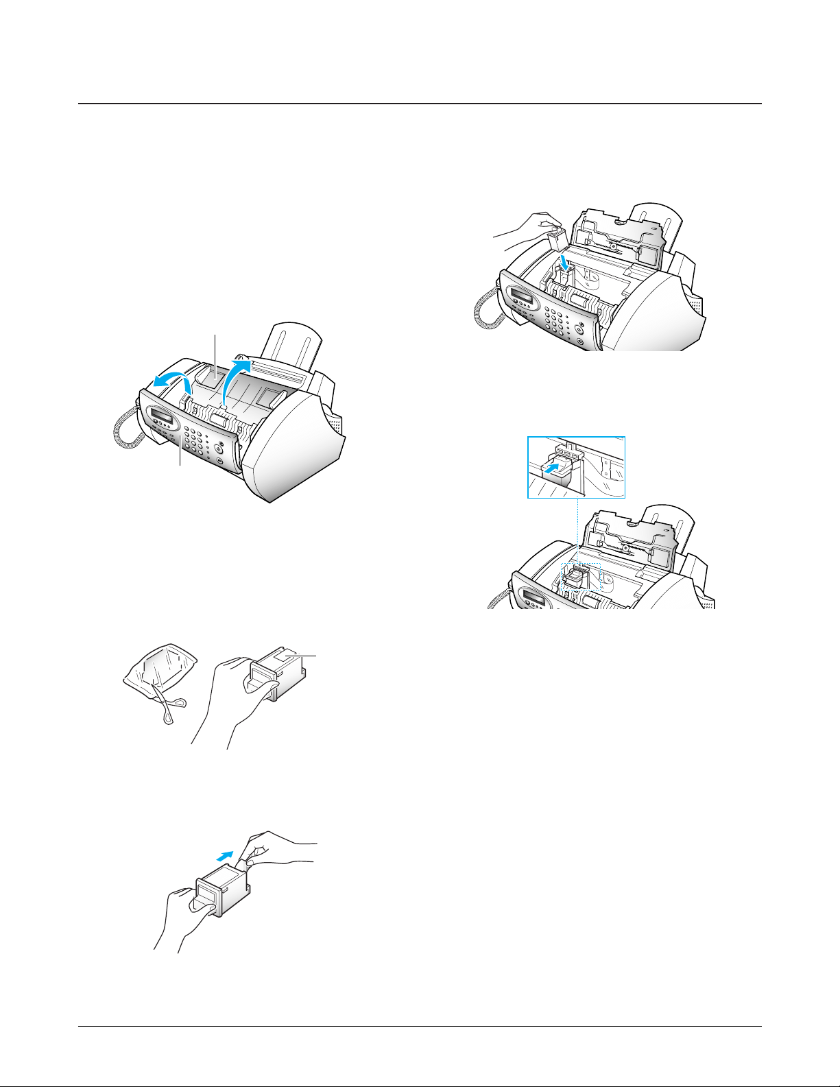
3-1-8. Backup Battery (SF3000T only)
1. Lift the control panel ➀ and open the cartridge
compartment cover ➁.
2. Remove the old battery, if necessary.
Connect the new battery to the clips.
3. Insert the battery into the battery slot.
The battery maintains setup configuration and
messages when a power failure occurs or when
power is accidentally disconnected.
We recommend you use an alkaline battery
because it lasts longer than a conventional
battery.
4. Close the cartridge compartment cover, and close
the control panel.
The battery can maintain the internal memory for
about 20 hours. If the backup battery is weak or
missing, the LCD displays a warning message.
➀
➁

1. Pull the paper support on the paper bin all the
way up.
2. Fan and insert the paper, with the printing side
facing you.
3. Squeeze the left paper guide and move it to the
right to match the width of the paper.
Note: The machine is preset to load A4-size paper.
To load letter or legal-size paper, you have to
set ÔPAPER SIZEÕ option to the desired size.
3-4 Samsung Electronics
Installation
3-2. Loading Paper
The display shows ÔPAPER EMPTYÕ when paper is not loaded. You can load approximately 100 sheets of paper.
Paper Guide
Paper support
Samsung Electronics 3-5
Installation
1. Press Menu.
2. Press ¹ or until Ô1.CHANGE CART.Õ is
displayed, then press Start/Copy.
3. Lift the control panel ➀, and open the cartridge
compartment cover ➁.
4. Remove the new print cartridge from its
packaging. Hold by the black areas or colored
top only. Do not touch the copper area.
5. Carefully remove the tape covering the
printhead. Be sure to remove all the tape.
6. Insert the print cartridge in the carrier.
7. Push the cartridge firmly in the direction of the
arrow until it clicks into place.
8. After installing the print cartridge, close the
cover and replace the control panel.
9. The display shows Ô:NEW :USED.Õ Press
Start/Copy to confirm ÔNEWÕ. (For used
cartridge, press ¹ or then press Start/Copy.)
The display briefly shows ÔMONO INSTALLED.Õ
If the cartridge is not installed properly, ÔNO
CARTRIDGEÕ is displayed. Remove the cartridge
and re-insert it.
10. The display asks if you want to run a SELF
TEST. Press Start/Copy to run the printer self
test.
If you press Stop, the machine returns to
Standby mode.
11. The machine prints out a test pattern of the
printer.
3-3. Installing Print Cartridge
When the machine is powered up without the print cartridge installed, the LCD displays ÔNO CARTRIDGE Õ.
Cartridge compartment cover
➀
➁
copper area
Control panel

3-6 Samsung Electronics
Memo
Installation
6. Disassembly and Reassembly
6-1. General Precautions on Disassembly
Samsung Electronics 6-1
When disassemble and reassembling components, use extreme caution. The close proximity of cables to moving
parts makes proper routing a must. If components are removed or replaced, any cables
disturbed by the procedure must be replaced as close as possible to their original positions. Before removing
any component from the machine, note the cable routing that will be affected.
Whenever servicing the machine, you must perform the following:
1. Check that documents are not stored in memory.
2. Remove the print cartridge.
3. Unplug the power cord.
4. Work on a flat and clean surface.
5. Replace only with authorized components.
6. Do not force plastic components.
7. Make sure all components are in their proper position.
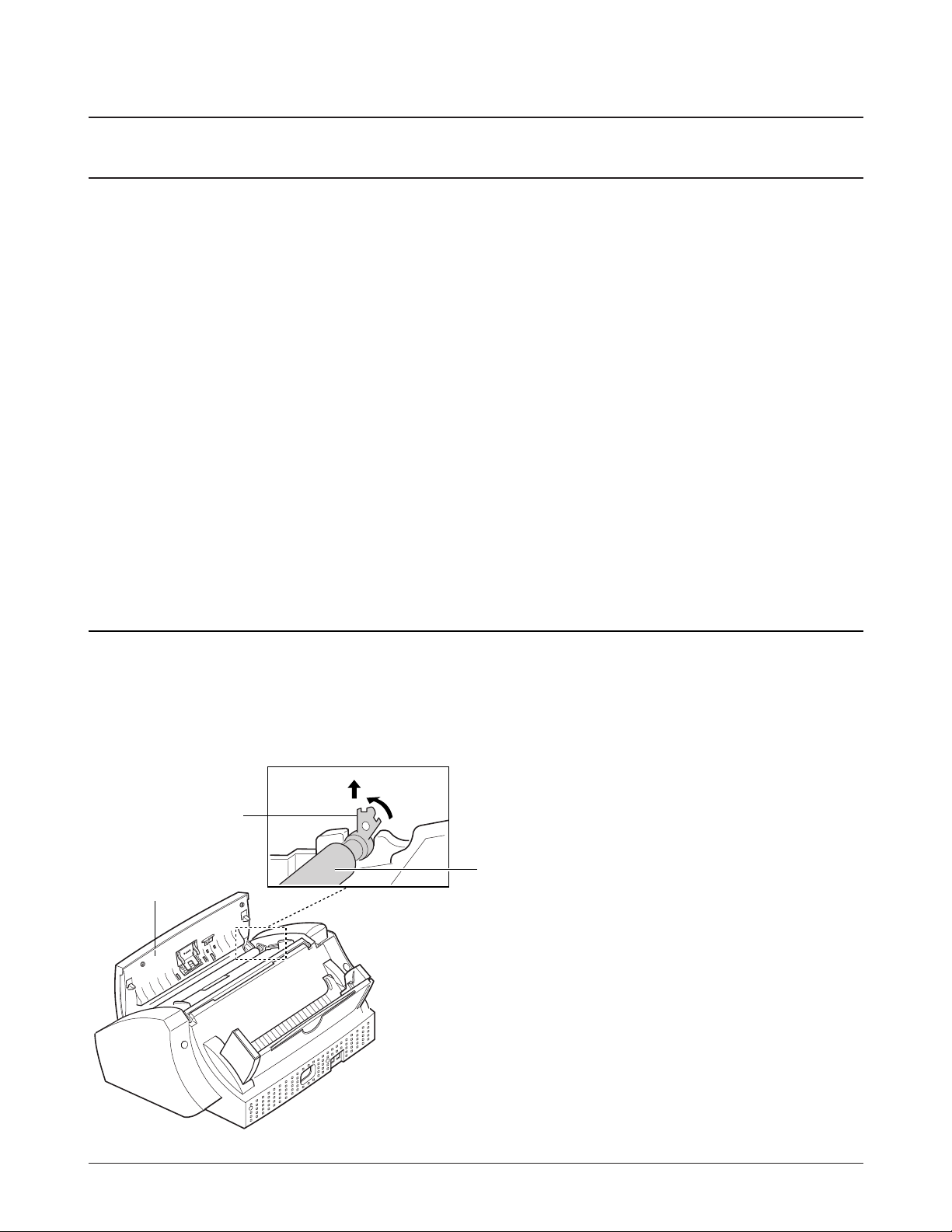
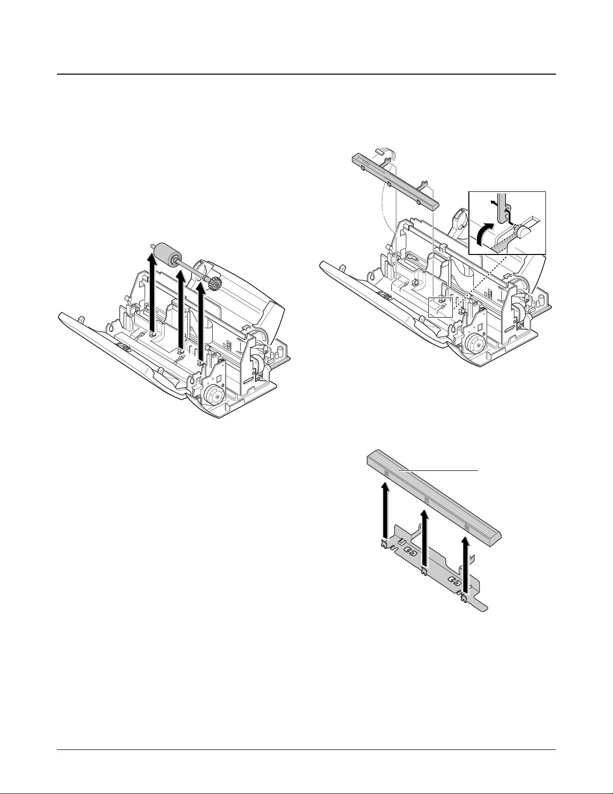
1. Lift the control panel.
2. Push the white clip on each end of the roller
slightly inward, then rotate it until it reaches the
slot, as shown below. Then lift the roller out.
Note : Check the roller for dirt. If dirty, wipe it off
with soft cloth dampened with water. If the
roller is heavily worn, replace it with a new
one.
6-2. White Roller
white clip
Control panel
White roller
B
A
6-2 Samsung Electronics
Disassembly and Reassembly
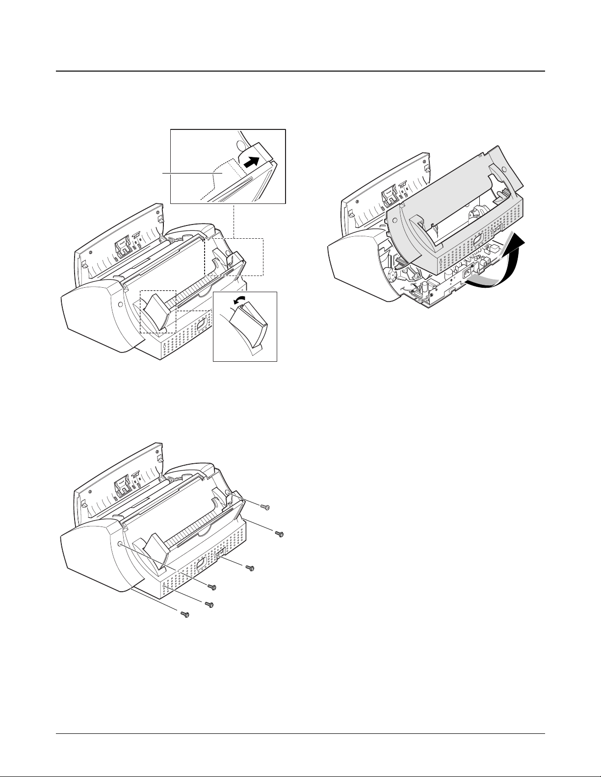
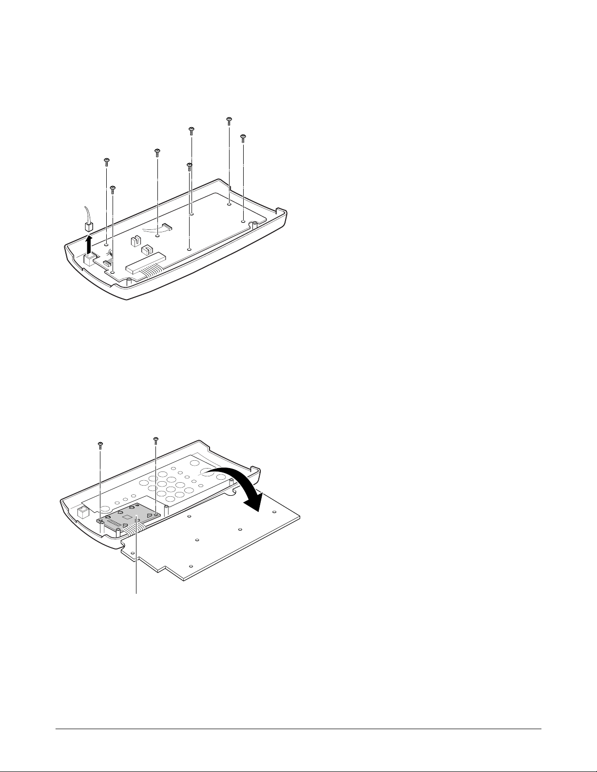
6-3. Rear Cover
1. Holding the paper guide, move it in the direction
of arrow.
2. Remove the six screws, as shown below.
3. Holding the rear cover assÕy, take it out by
rotating it to release properly.
Paper guide

1. Before you disassemble the top cover, you should
remove:
Ð Rear Cover (see page 6-2)
2. Remove the handset, and unplug the connector
from the main board.
3. Release the tie stopper supporting the control
panel.
4. Remove the four screws securing the cover.
5. If you want to remove the speaker, turn the top
cover over, and remove the two screws securing
it.
6-3Samsung Electronics
Disassembly and Reassembly
6-4. Top Cover and Speaker
Tie stopper
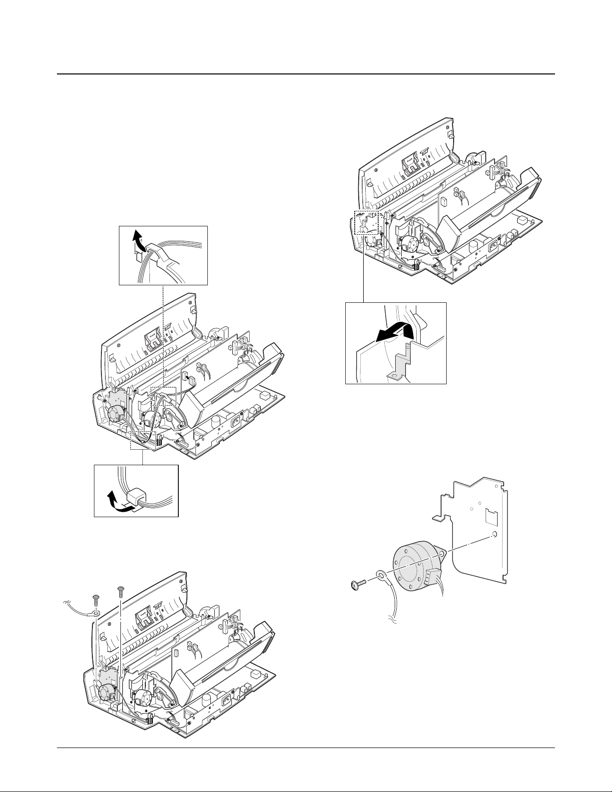
1. Before disassembling the scan motor, you should
remove:
Ð Rear Cover (see page 6-2)
Ð Top Cover (see page 6-3)
2. Unplug the motor connector from the main
board. Make sure the harness is released from the
two hooks, as shown below.
3. Remove the two screws as shown below.
4. Remove the ground plate.
5. Remove the ground screw securing the motor to
the motor bracket.
6-4 Samsung Electronics
Disassembly and Reassembly
6-5. Scan Motor
Ground plate
Samsung Electronics 6-5
Disassembly and Reassembly
6-6. ADF Roller and Contact Image Sensor (CIS)
1. Before disassembling the roller and CIS, you
should remove:
Ð Rear Cover (see page 6-2)
Ð Top Cover (see page 6-3)
2. Remove the ADF roller. When you assemble the
roller, make sure it is properly hooked.
Note : Clean the surface of the roller with ethyl
alcohol. After wiping it, you must dry it
completely.
3. Unplug the CIS harness, then remove the CIS
assÕy. To remove the CIS assÕy, turn it up and
slide the two legs far left, and pull it up.
4. Remove the CIS from the bracket.
Note: Check the glassy surface of the CIS for stains
or scratches. If stained, wipe off with ethyl
alcohol. If it is heavily scratched, replace it
with a new one.
CIS

6-6 Samsung Electronics
Disassembly and Reassembly
1. Before disassembling the SMPS, you should
remove:
Ð Rear Cover (see page 6-2)
2. Unplug the SMPS connector from the main
board. Make sure the harness is released from the
hook.
3. Remove the two ground screws from the bracket,
as shown.
4. Pushing down the hook, as shown in the inset,
remove the SMPS.
6-7. SMPS
1. Before disassembling the board, you should
remove:
Ð Rear Cover (see page 6-2)
Ð Top Cover (see page 6-3)
2. Remove the screw securing the ground wires to
the SMPS bracket.
3. Pulling the snaps locking the board outward,
remove the board.
4. Unplug all the connectors from the board.
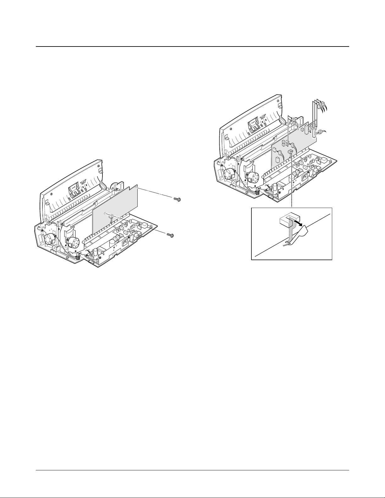
Samsung Electronics 6-7
Disassembly and Reassembly
6-8. LIU Board
Snap fit
6-8 Samsung Electronics
Disassembly and Reassembly
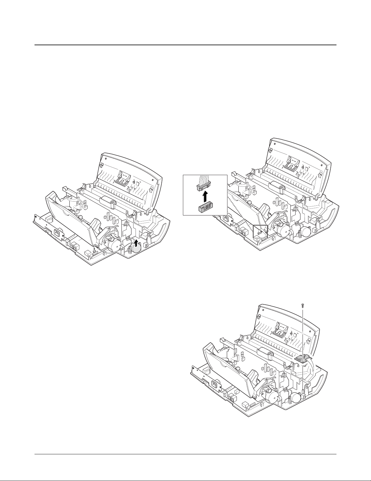
6-9-1. Buzzer
1. Before disassembling the buzzer, you should
remove:
Ð Rear Cover (see page 6-2)
Ð Top Cover (see page 6-3)
2. Unplug the connector from the LIU board, and
remove the buzzer.
6-9-2. Hook Board
1. Before disassembling the board, you should
remove:
Ð Rear Cover (see page 6-2)
Ð Top Cover (see page 6-3)
2. Unplug the connector from the LIU board.
3. Remove the screw, then remove the board.
6-9. Buzzer and Hook Board
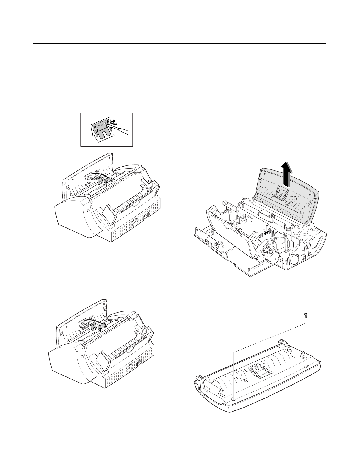
6-10-1. ADF Rubber Pad
1. Open the control panel.
2. Insert a flat blade screw driver into the slot as
shown below, and remove the rubber holder and
the rubber pad.
Notes:
¥ When reassembling the rubber pad, be sure that it
and the holder fit into the guide boss and the
holder latches fit into the corresponding hole.
Then push firmly until it clicks.
¥ Clean the surface of the rubber pad with ethyl
alcohol. After wiping, be sure to dry it. Check for
rubber wear. If the wear reaches 1/2 its original
thickness, replace it with a new one.
6-10-2. OPE Unit
1. Before disassembling the OPE unit, you should
remove:
Ð Dummy ASF (see page 6-2)
Ð Rear Cover (see page 6-2)
Ð Top Cover (see page 6-3)
Ð LIU Board (see page 6-7)
2. Unplug the connector from the main board, and
pull up the OPE unit.
3. Remove the two screws and remove the cover.
Samsung Electronics 6-9
Disassembly and Reassembly
6-10. OPE Unit
Rubber pad
Rubber holder
6-10 Samsung Electronics
Disassembly and Reassembly
4. Remove the microphone (SF3000T only) and the
seven screws.
5. Remove the OPE board. Then remove the two
screws from the LCD and remove the LCD.
Notes:
¥ Do not turn the OPE unit upside down after you
remove the screws securing the board. Keys and
rubber contacts may be separated and easily lost.
¥ When reassembling the OPE unit, make sure the
keys are in correct position.
¥ When reassembling the board, secure the screws
according to the order printed on the PBA.
¥ After reassembling, operate the machine to make
sure it works properly.
¥ After reassembling, make sure the LCD is not
blocked.
LCD
Microphone
(SF3000T only)
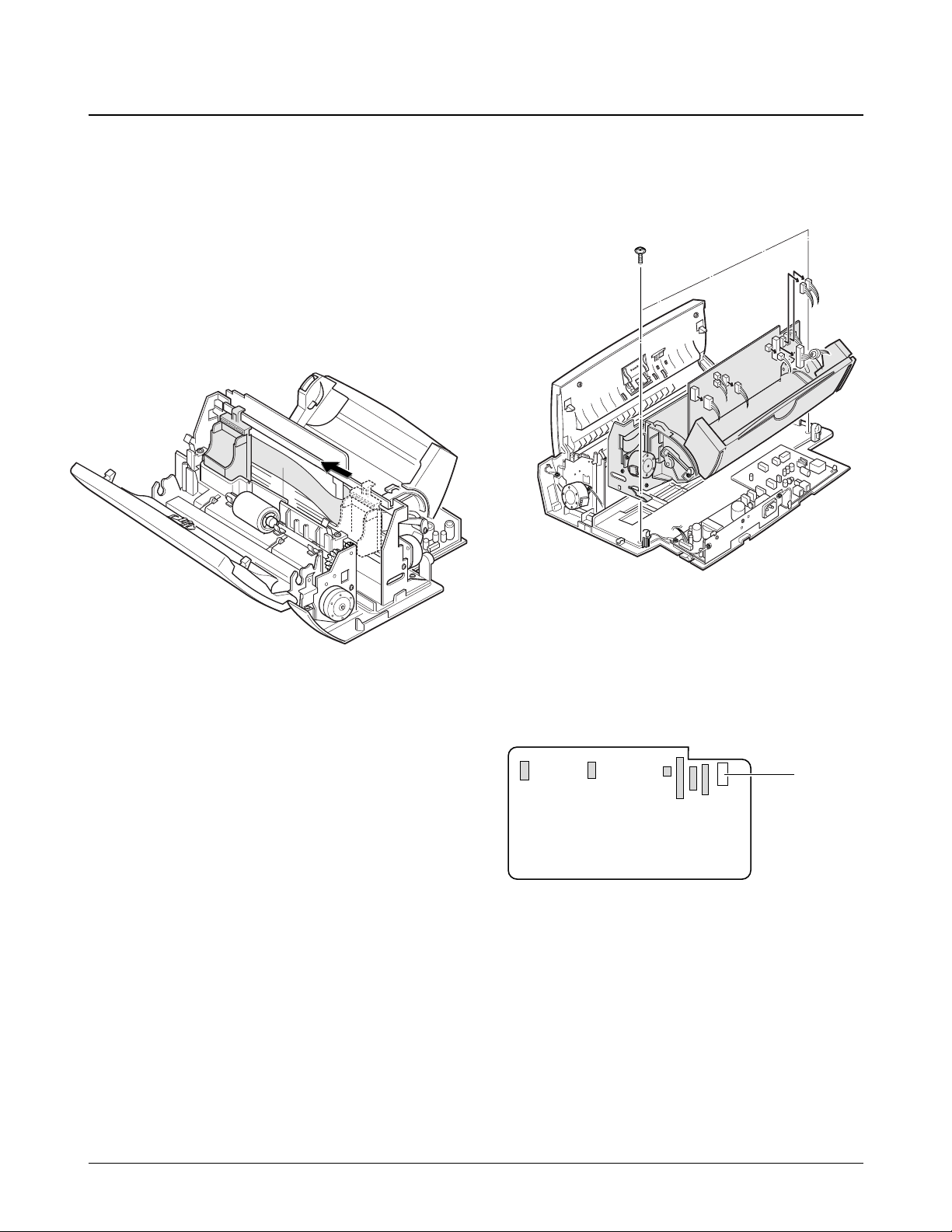
1. Before disassembling the printer unit, you should
remove:
Ð Dummy ASF (see page 6-2)
Ð Rear Cover (see page 6-2)
Ð Top Cover (see page 6-3)
2. Slide the cartridge carrier, as shown below.
3. Remove the two screws securing the printer unit,
and unplug the six connectors from the main
board.
The connectors are located as shown below. It is
not necessary to unplug the LF motor connector
to remove the printer unit.
4. Remove the printer unit. When you pull up
printer unit, be careful to properly release the
harnesses.
Samsung Electronics 6-11
Disassembly and Reassembly
6-11. Printer Unit
LF motor

6-12 Samsung Electronics
Disassembly and Reassembly
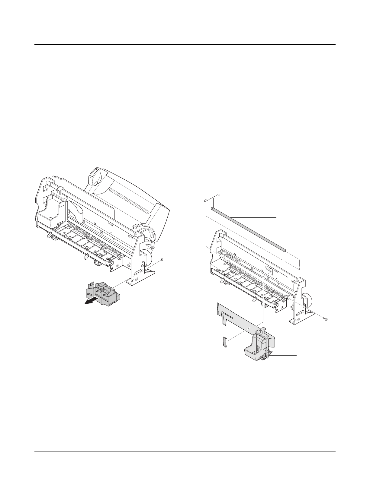
1. Before disassembling the ASF feeder assÕy, you
should remove:
Ð Dummy ASF (see page 6-2)
Ð Rear Cover (see page 6-2)
2. Remove the two screws securing the ASF feeder.
3. Unlock the ASF feeder assembly, and remove it.
4. Remove the screw securing the pickup shaft. To
remove the pickup shaft, pull it to the far right
and take it out.
Note : When reassembling the ASF feeder assÕy,
insure the harness for the line feed motor is
not pinched or shorted.
6-12. ASF Feeder
Pickup shaft
6-13-1. Cartridge Carrier Home Assembly
1. Before disassembling the cartridge carrier home,
you should remove:
Ð Dummy ASF (see page 6-2)
Ð Rear Cover (see page 6-2)
Ð Top Cover (see page 6-3)
Ð Printer Unit (see page 6-11)
2. Remove the screw securing the cartridge carrier
home, and take it out.
6-13-2. Cartridge Carrier Assembly
1. Before disassembling the cartridge carrier
assembly, you should remove:
Ð Dummy ASF (see page 6-2)
Ð Rear Cover (see page 6-2)
Ð Top Cover (see page 6-3)
Ð Printer Unit (see page 6-11)
Ð Cartridge Carrier Home Assembly
(see page left)
Ð ASF Feeder (see page 6-12)
Ð Main Board (see page 6-15)
2. Remove the cable holder, and remove the screw
on the right side of the frame.
Samsung Electronics 6-13
Disassembly and Reassembly
6-13. Printer Unit Miscellaneous
Carrier shaft
Carrier
Holder
6-13-3. Base Frame Assembly
1. Before disassembling the base frame assembly,
you should remove:
Ð Dummy ASF (see page 6-2)
Ð Rear Cover (see page 6-2)
Ð Top Cover (see page 6-3)
Ð Printer Unit (see page 6-11)
Ð Cartridge Carrier Home Assembly
(see page 6-13)
Ð Cartridge Carrier Assembly (see page 6-13)
Ð ASF Feeder (see page 6-12)
Ð Main Board (see page 6-15)
2. Remove the roller friction assemblies, then the
actuator feed.
3. Remove the base frame assembly.
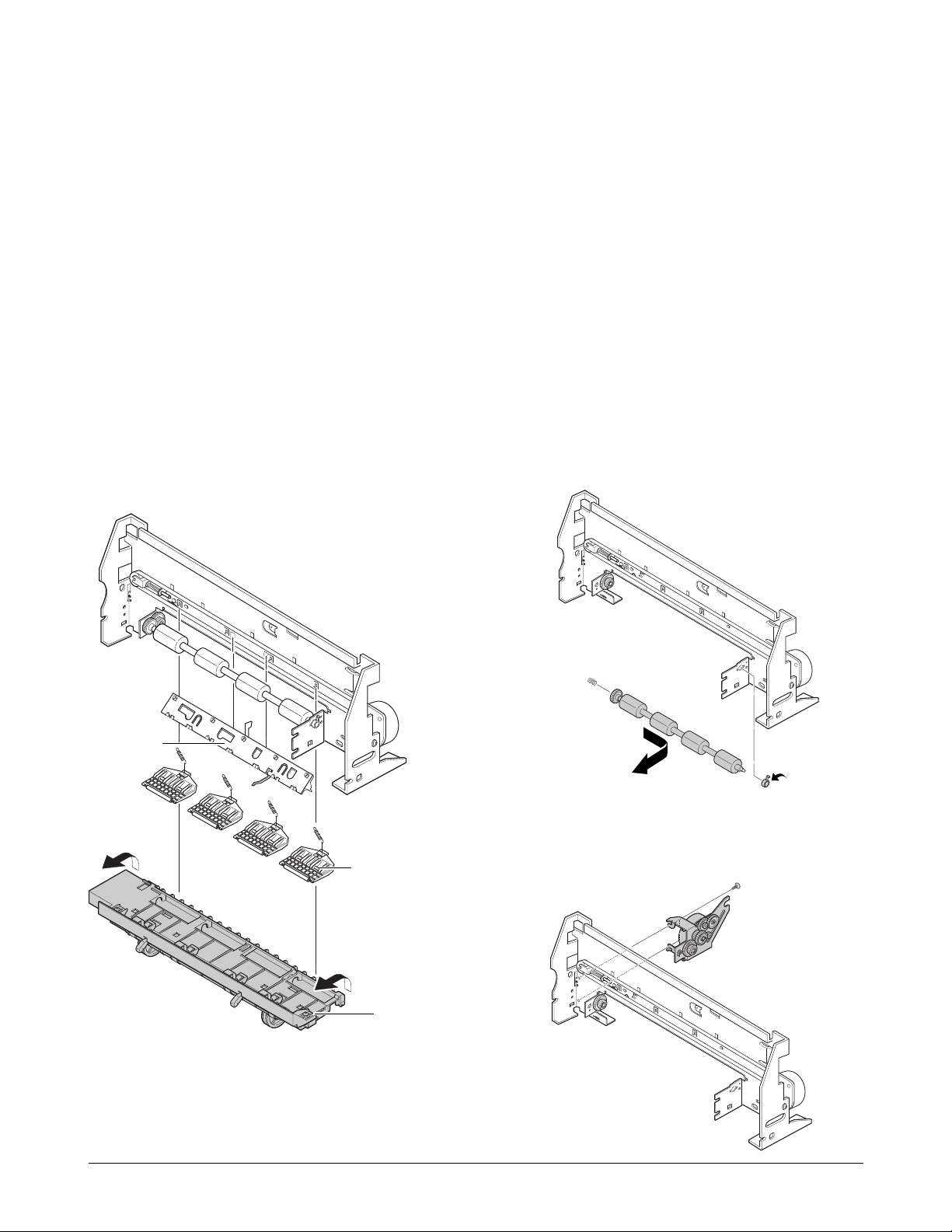
6-13-4. Feed Roller Assembly and Line
Feeder Bracket Assembly
1. Before disassembling the feeder roller assÕy,
and/or the line feed bracket assÕy, you should
remove:
Ð Dummy ASF (see page 6-2)
Ð Rear Cover (see page 6-2)
Ð Top Cover (see page 6-3)
Ð Printer Unit (see page 6-11)
Ð Cartridge Carrier Home Assembly
(see page 6-13)
Ð Cartridge Carrier Assembly (see page 6-13)
Ð Base Frame Assembly (see page left)
2. Remove the feed bearing from the main frame.
Pull the feeder roller in the direction of arrow,
and take it out.
3. Remove the two screws, then remove the feeder
bracket assembly.
6-14 Samsung Electronics
Disassembly and Reassembly
Holdr Roller
Roller friction assÕy
Base frame assÕy
Samsung Electronics 6-15
Disassembly and Reassembly
1. Before disassembling the main board, you should
remove:
Ð Dummy ASF (see page 6-2)
Ð Rear Cover (see page 6-2)
Ð Top Cover (see page 6-3)
Ð ASF Feeder (see page 6-12)
2. Remove the two screws securing the main board.
3. Unplug all connectors from the main board.
Then, pull the sensor lever towards you and
remove the main board.
6-14. Main Board
Sensor lever

6-16 Samsung Electronics
Disassembly and Reassembly
Memo
5. Circuit Description
5-1. General
The main circuit board consists of a Jupiter-2 Chip (KS32C6500), memory, TX- and RX-related circuitry, and
some portions of the Line interface Unit, and controls the system.
5-2. System Control Part
This circuit consists of the EP-ROM and SRAM, External Real Time Clock crystal, RTC and memory back-up,
and the Jupiter-2 Chip (KS32C6500). The Jupiter-2 Chip is an integrated 14400bps modem, image processor, 16bit MPU, peripheral control, and analog front end circuit on a single-chip.
The modem is 14400 bps half duplex. It is a monolithic device incorporating an over sampling Σ∆ AFE, digital
filters, a digital signal processor (SDIP4) and CPU-Interface logic.
5-2-1. Memory Map
The external memory of the CPU is divided into 32kB RAM (0000H through 7FFFH), 512kB ROM (FC0000H
through FFFFFFH) and 1024kB DRAM (010000H through 07FFFFH).
Samsung Electronics 5-1
Figure 5-1 KS32C6500 External Memory Map
CPU (Logical) Address Space
FFFFFF
FC0000
ROMCSn
CAS0
CAS1
CAS2
C00000
400000
800000
000000
MCSn
Internal
Registers
CS2n CS4n
CS1n
Internal
Memory
00FFFF
00FF00
00FE00
00FD00
00FC00
00E000
Reserved
Setup
Registers
Operational
Registers
CS4n
CS3n
CS2n
Reserved
Shading Inversion
DBCMC Buffer
Dither Table
Reserved
00FEFF
00FEE0
00FE80
00FE00
00FDFF
00FDC0
00FD80
00FD00
00FBFF
00FBE0
00FBD0
00FBC0
00FB80
00E000
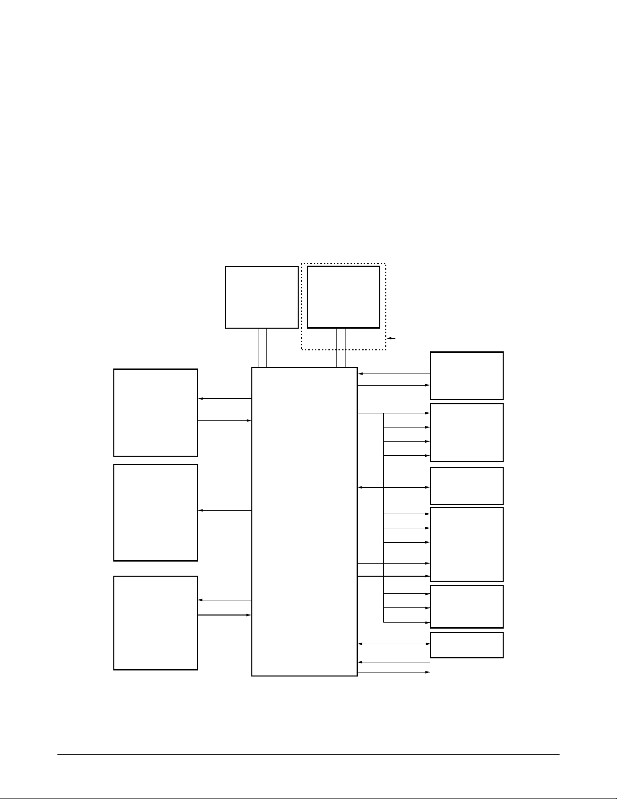
5-2-2. Jupiter-2 Chip
KS32C6500 internal logic generates chip select
signals for both memory chips and peripherals. To
support external access, from one to three wait
cycles can be inserted under program control during
external accesses. A chip select signal line goes
active (low) whenever its corresponding device is
accessed over the external interface. The peripheral
addresses are located in data memory.
/SRAMCS : SRAM chip select active (low)
/ ROMCS : EP-ROM chip select active (low)
D0ÐD15 : 16 bit data bus
A0ÐA17 : address bus
5-2-3. System Clock
The 30 MHz internal system clock frequency is
supplied by an external clock generator.
5-2 Samsung Electronics
Circuit Description
Figure 5-2 Hardware Interface Signals
OPERATING
PANEL
SERIAL
COMMUNICATION
HEAD
DRIVER
RTC
CRYSTAL
(32, 768KHZ)
SDIP4 TAD PART
KS32C6500
MOTOR
DRIVER
(CR, LF
MOTOR)
DATA
MEMORY
(SRAM)
PROGRAM
MEMORY
(EPROM)
DRAM.
(USER MEMORY)
GENERAL
PURPOSE I/ 0
TXD
A0~A5
D0~D15 D0~D7
CONTROL
RXD
PHINA~D
CONTROL
+24
XIN
ONLY SF3000T
XOUT
/DMS
/RD/WR
D0~D7
A0~A14
/RD
/LCAS
/RASO~
/UCAS
D0~D15
A0~A17
/A16
/PMS
/RD/WR
D0~D7
A0~A4
/RESET
/RESTO
MODEM
 Loading...