

Page 1

10. Designation of Main Components
10-1 Normal / Reverse Revolution of Motor and R. P. M. Control
89
510
89
Rotor
Stator coil
Rotor
Stator coil
10
+
CW
-
+
CCW
5
-
123456
D
E
E
P
S
H
G
I
H
O
H
C
A
T
D
E
E
P
S
E
L
D
D
I
M
R
O
T
A
T
S
789
R
O
T
C
E
T
O
R
P
STATOR
5
WASHING MOTOR
<Figure1> <Figure2>
(
±7%)
Resistance
value
Rated
value
STATOR(5.10) STATOR(5.1) ROTOR(8.9) TACHO(3.4) PROTECTOR(6.7) "H"(mm) Code-No. Remark
2.07
Ω
0.90
Ω
2.35
Ω
34.
3Ω
220~240V/50Hz
10-2 Door safety Device (F1213J/F1013J/F813J)
10
)
C
0
5
1
(
R
O
T
O
R
H
0 45 DC31-00002E
When Door is closed, door stay closed. if "set" is operated, power supplied to , wires have bymetal keep
the door closed, and electronical power flows between and make it operate.
24
Page 2

10-3 Heater
1) Capacity : AC 230V/1900W
2) Location : Bottom of TUB
3) Function : Raise the water temperature
supplied at the wash process.
4) Resistance value : 23~29
5) Thermal Fuse : 128° C
Thermistor
10-4 Detergent tub and water supply value
A Detergent tub is composed of housing and 3 drawers . supplied water flows into the 3 drawer-detergent tub by
way of classifier at each washing process.
three open drainage way whith detergent and supplied water by way of connector located under the housing flows
into washing tub.
the water supply valve is composed of a hot water valve(1 way) and a cold water valve(2way) and water flow per
mininthevalveisbelow.
Hot water valve(1 way)
(OPTION)
water flow(L/min)
resistance value
power consumption
usable water pressure
10L 10L 5L
㏀
4.3
AC 220v ~ 240V 50/60
10-5 Shock absorber and buffer spring
This wash machine is equipped with 2 Shock absorbers with same
capacity and with 4 buffer springs. 2 Shock absorber are placed
under the tub and outside case , 4 buffer springs are placed on the
right and left of the upper side of outside case.
Shock absorber function: during wash, dehydration absorb the shock.
buffer spring: buffering the vibration
device
Shock absorber 8±2kg
capacity of Shock absorber
Cold water valve(2 way)
V1 V2
㏀
4.2
㎐
0.5 ~ 8㎏/
㎤
4.2
㏀
25
Page 3
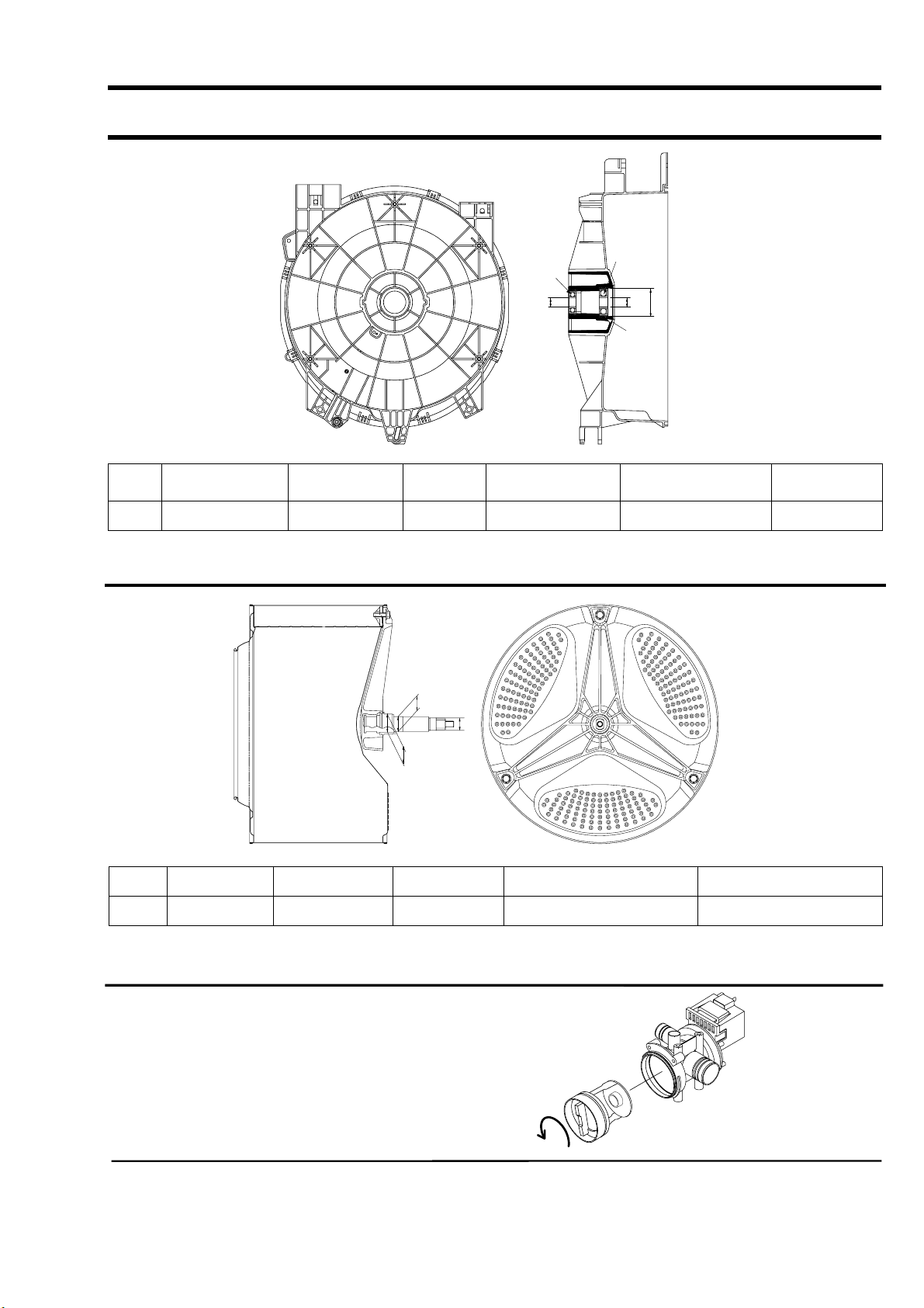
10-6 ASSY-TUB BACK
INNER-BEARING
A
C
OIL-SEAL
Assy-Tub Back REMARK
TYPE INNER-BEARING(A) OUT-BEARING(B) OIL-SEAL(C)
OUT-BEARING
B
Assy-Housing
Bearing(D)
I ø20 ø17 ø24.3 DC97-00125D DC97-00214K
10-7 ASSY- DRUM
A
B
(unit : mm)
C
TYPE
(A) (B) (C) CODE-NO. REMARK
I ø20 ø17 ø25 DC97-01463J Lifter type
10-8 ASSY-PUMP DRAIN
1) Capacity : AC 230V 34W
2) Location : Front bottom(R)
3) Resistance : 160Ω~190
Ω
26
(unit : mm)
 Loading...