

Page 1
7. General Error Function
An occurrence of an Error will make a sound of error melody for 5sec and continuously show one of the Error
1.
Displays from the following errors. (But, Fault Check Led will flash for 0.5sec.)
All of the steering parts will be off at that time until that error was released.
2.
3. Water Supply Error
- If there is no higher change in water frequency than 100Hz for 2 minutes during the initial time of water supply
and if water level doesn't reach the preset level in 20 minutes, this error will occur.
This error will be released using Start/Pause button, which performs the initial condition of operation.
-Display:
4. Water Drain Error
- If water level frequency is still lower than the reset level frequency (24.50kHz) in 10 minutes after starting of
water drain, this error will occur.
This error will be released using Start/Pause button, which performs the initial condition of operation.
-Display:
5. Over Flow Error
- If an abnormal water level frequency is sensed (for occurrence of Over Flow :20.50kHz), Auto Power Off may
release this error and continuously progress water drain until the frequency reached 24.50kHz.
- If Over Flow is also sensed even after the following check of water level frequency indicating that error, it
functions to progress water drain.
-Display
6. Door Open Error
- This error will be released by opening Door.
-Display:
“4E”
“5E”
”
:“OE
"in2-digit,"
"dE
"in4-digit
door
7. Unbalance Error
- This error will be released by turning off Power S/W, which performs the initial condition of Power-On.
- DISPLAY :
8. Water Heater Error
- This error will be released by turning off Power S/W.
-Display:
-Display
9. Pressure S/W (Single Part Trouble) Error
※
Frequency signals(kHz) generated by water level S/W
Abnormal Frequency 30.00 KHz 15.00 KHz
- If the above frequency signals are displayed longer than 5sec, it indicates Pressure S/W Error.
- Drain water for 3 minutes for that Error, and turn OFF water drain pump. Pressure S/W Error
display
10. Abnormal Water Temperature ERROR
- Water drain begins if abnormal water temperature is sensed at the initial time of water supply. If the frequency
higher than 25.24KHz is sensed, water will be drained by force.
-Display
- This error will be released by turning off Power S/W.
“UE”
“
HE"(Over Heat),
: "6E", indicating no operation of HE.
Water Level
“
"willbeshown..
IE
:"CE"
Low High
13
Page 2

7. General Error Function
11. Natural Drain/Water Leak Error
- If more than 4 times of water supply and safe water level of Heater are sensed for each course, this error will
occur.
-Display:"
- This error will be released by turning off Power S/W.
12. Tacho Error
- If Motor Tacho is abnormal, this error will occur.
- If Tacho signals are inputted less than 2 for 2sec after Motor started, this error will occur.
-Display:"
- This error will be released by turning off Power S/W.
13. Motor TRIAC Short Error
- If Tacho signals are inputted more than 300 every 1sec in the operational interval less than 90RPM, this error
will occur.
Turn off Power S/W at that time.
-Display
- This error will be released by turning off Power S/W.
14. Thermistor Abnormal Error
- If Thermistor circuit is abnormal, this error will occur.
-IfThermistorislowerthan0.2Vorhigherthan4.5V,thiserrorwilloccur.
-Display
- This error will be released by turning off Power S/W.
LE
3E"
:"bE
:"tE"
"
14
Page 3
8. Trouble Diagnosis
- As the micom wash machine is configured of the complicate structure, there might be the service call.
Below information is prepared for exact trouble diagnosis and suitable repair guide.
Caution for the Repair and Replacement
Please follow below instruction for the trouble diagnosis and parts replacement.
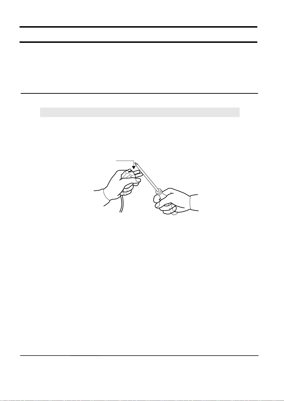
1) As some electronic components are damaged by the charged static electricity from the resin part of wash
machine or the human body, prepare the human body earth or remove the potential difference of the
human body and wash machine by contacting the power supply plug when the work contacting to PCB is
executed.
POWER SUPPLY PLUG
2) Since AC220~240V is applied to the triac T1 and T2 on P.C.B, the electric shock may occur by touching
and be careful that the strong and weak electricity are mixed.
3) As the P.C.B assembly is designed for no trouble, do not replace the P.C.B assembly by the wrong
diagnosis and follow the procedure of the trouble diagnosis when the micom is not operated normally.
15
Page 4
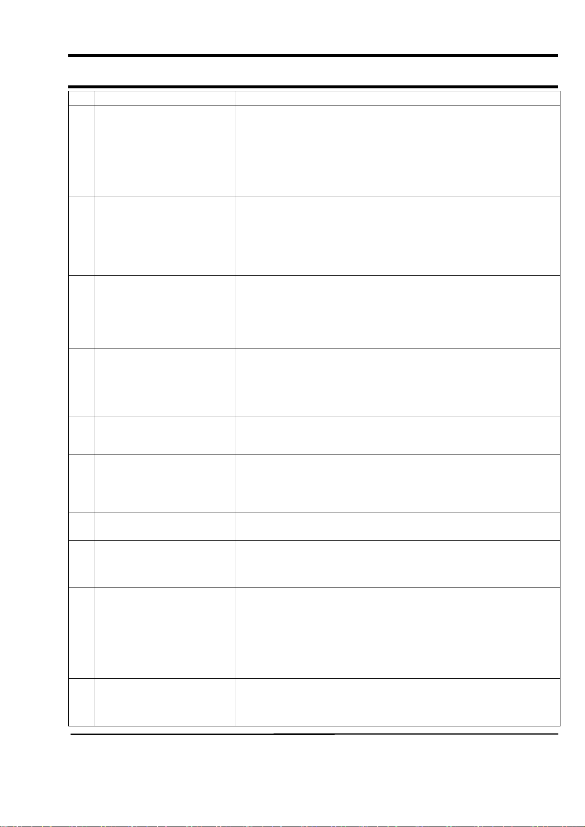
8-1. Trouble Diagnosis
No Item Cause and treatment
- Is the PCB connector connected well?
- Is the voltage normal?
- Is the power supply plug connected well?
1 The power is not supplied
2 The water is not supplied.
The wash does not start though
3
the water supply is stopped.
- Is the noise filter connected well?
- Is the secondary output of the power supply transformation normal?
- Is the fuse disconnected? (option)
• If above points are not found, the PCB assembly is out of order.
Replace it.
- Is the knob open?
- Did you push START/PAUSE button after selecting the course?
- Is the water supply valve connected well?
- Is the winding of the water supply valve continuous?
- Is the connection and operation of the pressure switch normal?
• If above points are not found, the PCB assembly is out of order.
Replace it.
- Is the connection and operation of the pressure switch normal?
- Is the pressure switch hose damaged so that the air is leaked?
- Is the pressure switch hose bent?
- Check the operation of the water level switch.
• If above points are not found, the PCB assembly is out of order.
Replace it.
The drum does not rotate during
4
washing.
The drum rotates by one direction
5
during washing. (The drum rotates
to one direction for SPIN.)
6 Drainage problem.
7 Dehydration problem.
8 Abnormal noise during SPIN.
Leak breaker or current/leak
9
breaker is down during washing.
10 The heating is not executed.
- Is the belt connected well?
- Is the winding of the motor continuous?
(Rotor winding, stator winding, generator)
- Is the motor protector normal?
• If above points are not found, the PCB assembly is out of order.
Replace it.
- The PCB assembly is out of order. Replace it.
(Inversion relay open trouble)
- Is the drainage hose bent?
- Is the winding of the drainage pump continuous?
- Is the drain filter clogged by the waste?
• If above points are not found, the PCB assembly is out of order.
Replace it.
- The unbalance is detected.
- Put in the laundry uniformly and start again.
- Is the pulley nut loosen?
- Is the transport safety device removed?
- Is the product installed on the level and stable place?
(Little noise may be generated during the high-speed SPIN.)
<When the leak breaker and current breaker is installed separately>
- When the leak breaker is down, check and make the earth of the outlet.
- When the current is down, the current is leaked.
<Is the breaker down when the leak/current breaker is combined?>
- Check the rated capacity of the current and leak breaker.
The current breaker may be down due to the lack of the current when the
wash machine and other apparatus are used.
In this case, execute the cold water wash to check whether the current capacity is lack.
- Is the wash heater terminal unplugged?
- Is the wash heater normal?
- If above points are not found, the PCB assembly is out of order.
Replace it.
16
Page 5

8-2 . Problem Checking And Method Of PCB
8-2-1 The Part Of Power Source
NO Power On
YES
The Voltage Of
BetweenⓐandⓑIs
As Big As 12V?
YES
NO
Check The Trans
TRANS
The Voltage Of
BetweenⓒandⓓIs
As Big As 12V?
YES
The Voltage Of
BetweenⓔandⓓIs
As Big As 5V?
YES
D11,12,16,17
ⓐ
ⓑ
D18
2200UF
CE3
ⓒ
NO
NO
IC3
7805
Check The Diode
(D11,D12,D16,D17,D18)
And Condenser(CE3)
Exchange IC3(7805) And
Check The
Condenser(CE5)
CE5
470UF
ⓓ
ⓔ
30
57
72
75
13
31
73
74
17
Page 6

8-2-2. Reset Part
Measurement Result Of
Between Micom 25 And
The Value Of
Gnd Is 5V?
YES
Check IC4
IC4
7533
NO
Check The Power Source
R40 100
25
CE7 1UF
8-2-3. Interrupt Part
Check The Curve
Output Of
Check The Micom
Number 67 ?
Check The Part Of
Oscillator
ⓐ
ⓐ
?
R28 2.2K
Check D11,12,16,17,18
Check TR2,R35
R35 4.7K
TR2
MMBT3904
67
C15
C21
R33 C13
18
Page 7

8-2-4. Checking The Part Of An Oscillator
When The Micom 22,23
Check, The Value Is
16Mhz?
YES
Exchange Micom And Check R42,R41
NO
Check Resonator
8-2-5. Check The Part Of Buzzer
ⓐ
Part Confirm DC12V ?
NO
R41 68
23
R42
1M
22
RESO1
16MHz
Check The Part Of Power Source
YES
Exchange BUZZER1,
Check R5,R46
ⓐ
BUZZER1
R5 1K
IC2
R46 10K
65
ⓑ
19
Page 8

8-2-6. Driving Part Checking
◆
Confirm The Output Of DC5V, W hen The Every Part Of Micom Number Check,
According To The Some Problem Condition
ex) When The Drain Is Not Operating But Pump Motor Is Operating, Check
The5VoltageOfMicom
Micom Number, 10 Is
5Voltage?
YES
The Part Of
ⓐ
Is
0 Voltage?
YES
Check R11, TRIAC1
RELAY6
NO
Micom Bad
NO
Check The IC 65003
MICOM
IC65003
ⓐ
RELAY4
12V
ⓐ
TRIAC2
TRIAC3
TRIAC1
※
Check The Micom 18th In The Above Method When The Cold Water Is Bad
R10
R7
R11
ⓐ
ⓐ
ⓐ
POWER
DOOR
PRE
COLD
PUMP
15
52
16
11
10
20
Page 9

8-2-7. Confirm The Driving Part Of Motor
Motor Is Not Spinning
NO
Motor Is Not Turning
Right And Left
NO
Check The Tacho Part
YES
Check BD1, TRIAC5
YES
Check RELAY1
CM1
R6
BD1
COIL1
RELAY1
CM5
R20
TRIAC5
12V
MICOM
IC 65003
R18
12
1W 300
6
D1
21
Page 10

8-2-8. Checking The Tacho Part
Have The Motor Turn In Hand
Is The Rectangular
Curve In The Micom 66?
YES
Exchange The Motor
R27
C8
R29
TR1
5V
NO
R30
C11
Check The Surroundings
Circuit And TR1,IC7
5V
IC7
2
3
5
4
MICOM
66
22
Page 11

9. Test Mode
2
1
3
4
1. Driving Compartment Test Mode
A. Hold down “ 1” and “ 2” keys simultaneously and then press POWER S/W “ 4” on.
(Whole lamps turn on and display show “ t1” after 3 Seconds.)
B. The driving compartment can be tested when you press “ 3” key right after entering
into the initial stage of the TEST MODE.
• Driving Compartment Test
Pre-wash VALVE ON(0.3sec)→OFF(0.3sec)→COLD VALVE ON(0.3sec)→[OFF(0.3sec)
HOT VALVE ON (0.3sec) :
OPTION
]→OFF(0.3sec)→Rinse VALVE ON(0.3sec)→OFF(0.3sec)
Pump MOTOR ON(0.3sec)→OFF(0.3sec)→MOTOR Left (0.5sec)→OFF(0.5 sec)
→
→
→
MOTOR Right (0.5sec)→OFF(0.3sec)→HEATER RELAY ON(0.3sec)→OFF(0.3sec)→DOOR OPEN
(Function continues when door is closed)
2. THERMISTOR TEST MODE
A. Hold down “ 1” and “ 2” keys simultaneously and then press POWER S/W “ 4” on.
(Whole lamps turn on and display show “ t1” after 3 Seconds.)
B. Press the “ 1” key and display shows “ t2”
C. Press the “ 3” key and display shows the inside temperature of tub.
23
 Loading...