

Page 1
Level
8.
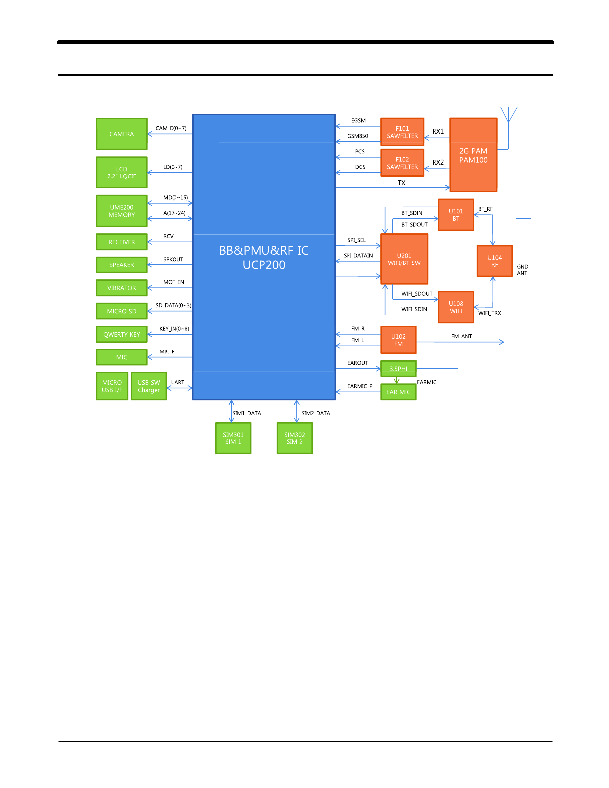
Block Diagram
8-1.
Repair
3
8-1
SAMSUNG Proprietary-Contents may change without notice
This Document can not be used without Samsung's authorization
Page 2
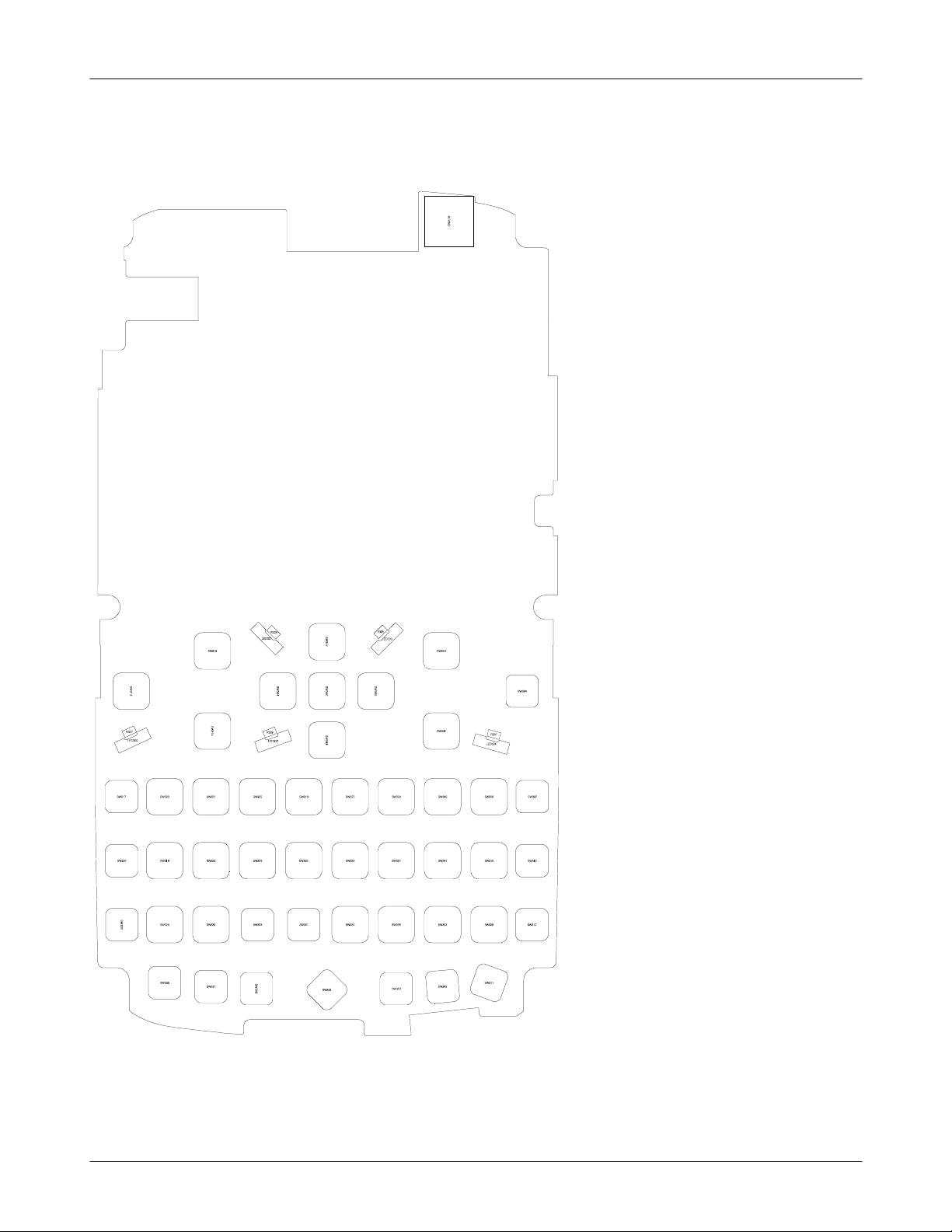
Level3Repair
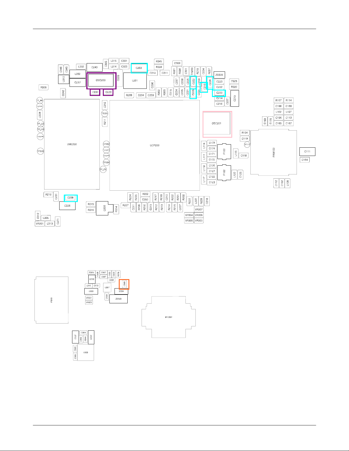
PCB Diagrams
8-2.
8-2-1.
Top
8-2
SAMSUNG Proprietary-Contents may change without notice
This Document can not be used without Samsung's authorization
Page 3
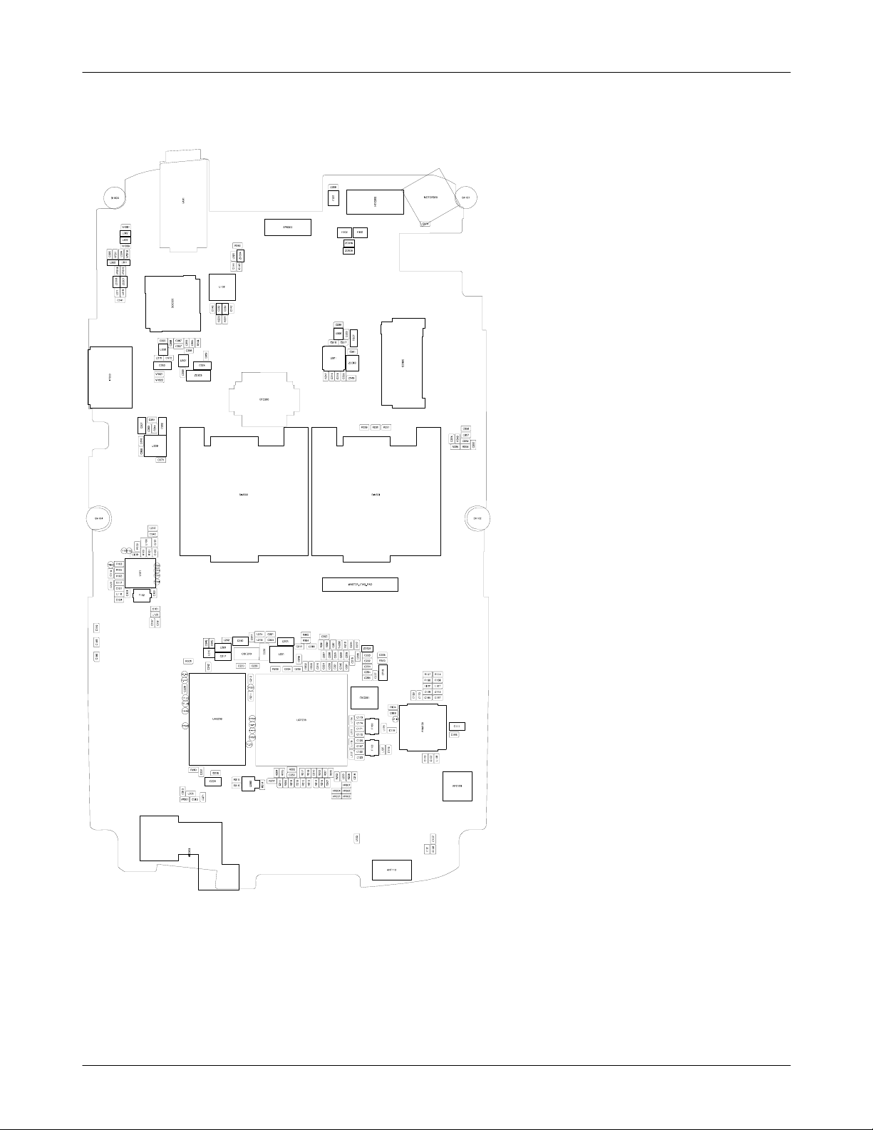
Level3Repair
8-2-2.
Bottom
8-3
SAMSUNG Proprietary-Contents may change without notice
This Document can not be used without Samsung's authorization
Page 4
Level3Repair
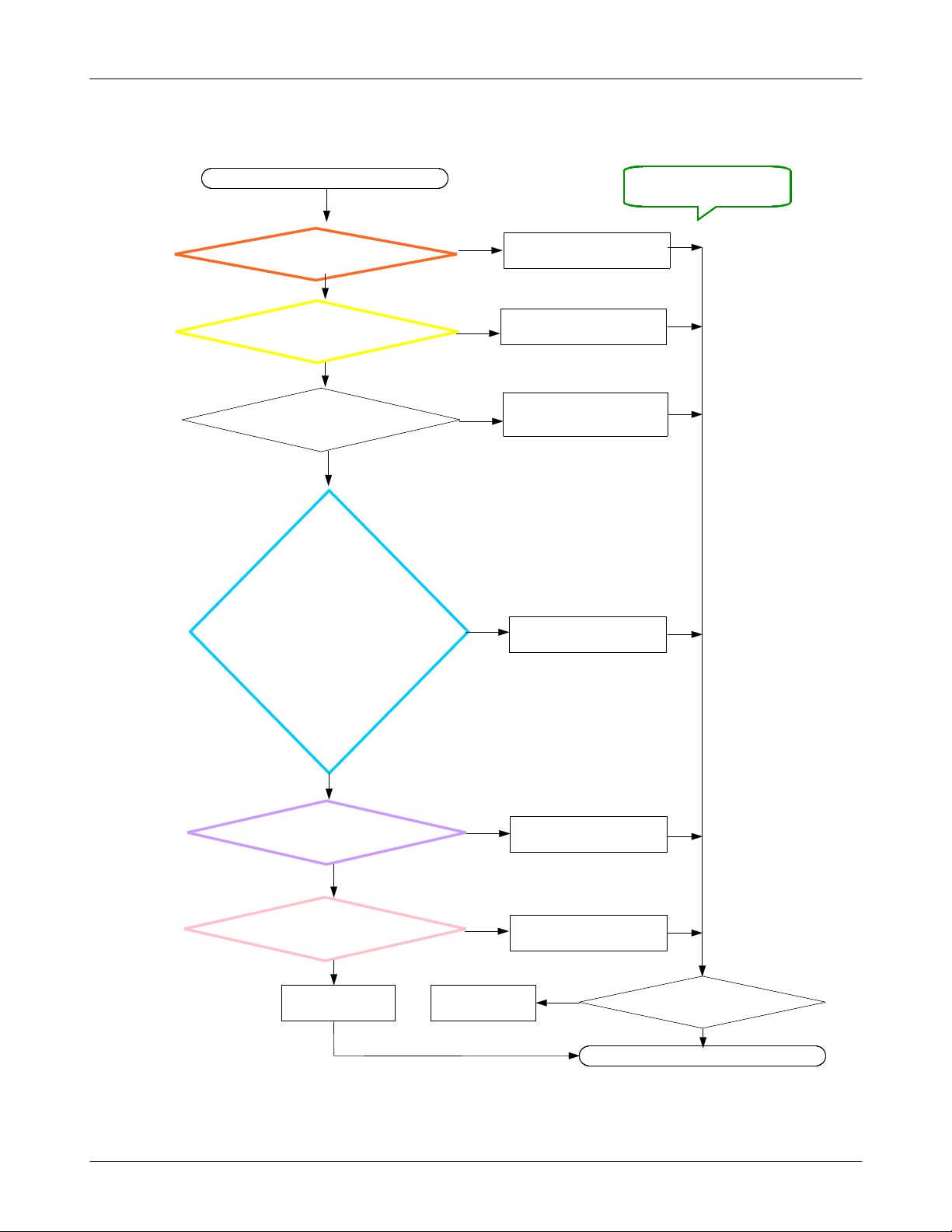
8-3-1.
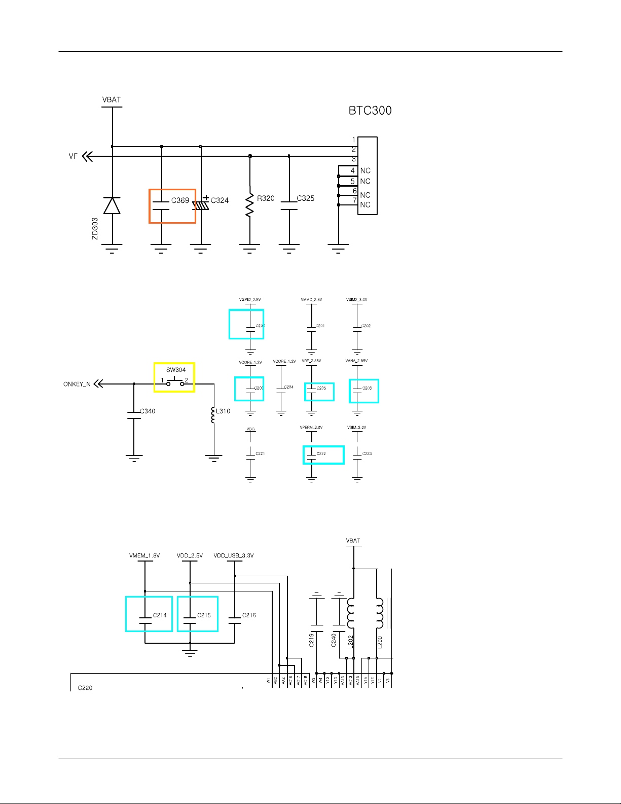
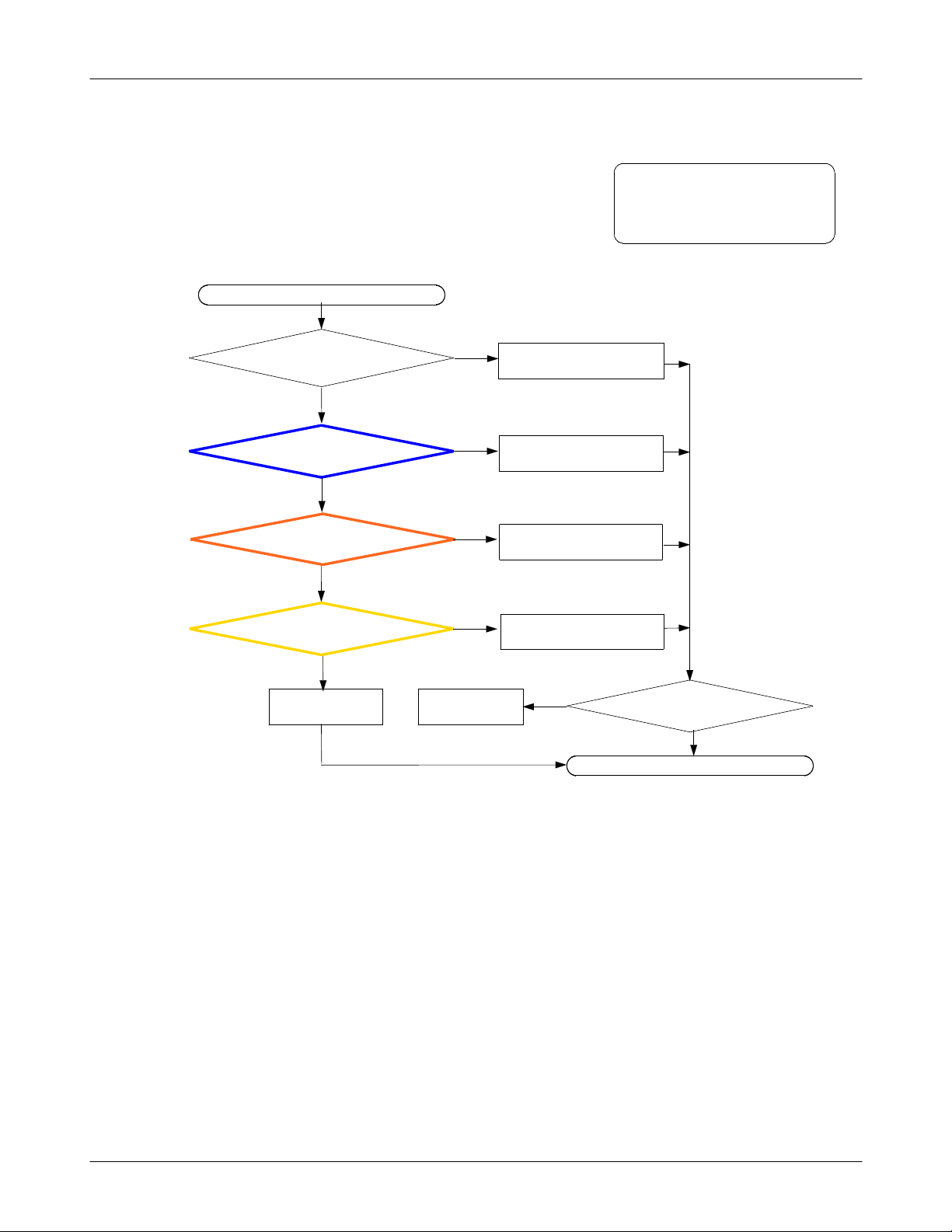
Power On
Power On"does not work
"
Check theVBAT Voltage
C369
@
>=3.3V
YES
Is the assembling status of
SW304(ON KEY) O.K?
YES
Current consumption
>= 100mA?
YES
Check the power
VRF_2.85V(C205)
VDD_2.5V(C215)
VGPIO_2.8V(C200)
VANA_2.85V(C206)
VCORE_1.2V(C203)
VPERM_3.0V(C222)
VMEM_1.8V(C208)
NO
NO
NO
NO
Charge the Battery
1.
V, put more lead
2.If0
C369
@
Reassemble DomeSheet
1.
Download binary again
power management problem.
If you
do
.
Put more lead solder
each terminal
#2!!!
try and fail,
#1
YES
Check the OSC
C229,230)=
(
Check the OSC201
OSC1PIN,3PIN>=26MHz
Replace Board(PBA)
32.768
200
YES
YES
KHz
NO
?
?
NO
Back to
previous step
inner clock problem.
Put more lead solder
each terminal
Put more lead soler
each terminal
NO
8-4
SAMSUNG Proprietary-Contents may change without notice
This Document can not be used without Samsung's authorization
Is It power turned on?
YES
END
Page 5
Level3Repair
8-5
SAMSUNG Proprietary-Contents may change without notice
This Document can not be used without Samsung's authorization
Page 6
Level3Repair
※
8-6
SAMSUNG Proprietary-Contents may change without notice
This Document can not be used without Samsung's authorization
Page 7
Level3Repair
8-3-2.
SIM part
"
Insert SIM card" is displayed on the LCD
Check the connection of
SIM300,301 to SIM card
YES
Check the SIM Module
YES
Check the voltage
C333,
@
349 = 3.0V ?
YES
Replace Board(PBA)
NO
NO
NO
Back to
previous step
insert SIM card again
after check connection
SIM300,301
Replace the SIM module
Put more lead each terminal
Does Phone accept
NO
the SIM card?
YES
END
8-7
SAMSUNG Proprietary-Contents may change without notice
This Document can not be used without Samsung's authorization
Page 8

Level3Repair
8-8
SAMSUNG Proprietary-Contents may change without notice
This Document can not be used without Samsung's authorization
Page 9
Level3Repair
8-3-3.
GSM
RX
850
Phone can't catch GSM850 network
NORMAL CONDITION
catch the channel?
PAM100 CHECK
RFS100
@
Check the connection
GSM850 RX LINE
Check the voltage
PAM100@C111
-65
≥
YES
dBm
YES
YES
≥3.0
?
V?
NO
NO
NO
NO
Put more lead solder
L100,L101,C108,C107,
@
RFS100,C102,L108
Put more lead solder
RFS100,L108,C102
Put more lead solder
C118,L115,F100,C173
C174,L114
Put more lead solder
each terminal
CONTINUOUS RX ON
RF INPUT
mplitude
A
@
: 190
:-50
CH
dBm
YES
Replace Board(PBA)
Back to
previous step
Does Phone catch
the GSM850 network?
YES
END
8-9
SAMSUNG Proprietary-Contents may change without notice
This Document can not be used without Samsung's authorization
Page 10
Level3Repair
8-3-4.
GSM900 RX
Phone can't catch GSM900 network
NORMAL CONDITION
catch the channel?
YES
PAM100 CHECK
RFS100
@
Check the connection
GSM900 RX LINE
dBm
-65
≥
YES
YES
CONTINUOUS RX ON
RF INPUT
mplitude
A
NO
NO
?
NO
Put more lead solder
L100,L101,C108,C107,
@
RFS100,C102,L108
Put more lead solder
RFS100,L108,C102
Put more lead solder
C118,L115,C171,C172,L111
F100
@
:62
:-50
CH
dBm
Check the voltage
PAM100@C111
Replace Board(PBA)
≥3.0
YES
NO
V
Back to
previous step
Put more lead solder
each terminal
NO
Does Phone catch
the GSM900 network?
YES
END
8-10
SAMSUNG Proprietary-Contents may change without notice
This Document can not be used without Samsung's authorization
Page 11

Level3Repair
8-3-5.
DCS RX
Phone can't catch DCS network
NORMAL CONDITION
catch the channel?
YES
PAM100 CHECK
RFS100
@
Check the connection
DCS RX LINE
dBm
-65
≥
?
YES
NO
NO
NO
Put more lead solder
L100,L101,C108,C107,
@
RFS100,C102,L108
Put more lead solder
RFS100,L108,C102
Put more lead solder
C125,L120,F103,C126
C127,L119
CONTINUOUS RX ON
RF INPUT
mplitude
A
@
: 698
:-50
CH
dBm
Check the voltage
PAM100@C111
Replace Board(PBA)
YES
≥
YES
3.0V ?
NO
Back to
previous step
Put more lead solder
each terminal
NO
Does Phone catch
the DCS network?
YES
END
8-11
SAMSUNG Proprietary-Contents may change without notice
This Document can not be used without Samsung's authorization
Page 12

Level3Repair
8-3-6.
PCS RX
Phone can't catch PCS network
NORMAL CONDITION
catch the channel?
YES
PAM100 CHECK
RFS100
@
Check the connection
PCS RX LINE
dBm
-65
≥
?
YES
NO
NO
NO
Put more lead solder
L100,L101,C108,C107,
@
RFS100,C102,L108
Put more lead solder
RFS100,L108,C102
Put more lead solder
C125,L120,F103,C122
C123,L117
CONTINUOUS RX ON
RF INPUT
mplitude
A
@
: 644
:-50
CH
dBm
Check the voltage
PAM100@C111
Replace Board(PBA)
YES
≥
YES
3.0V ?
NO
Back to
previous step
Put more lead solder
each terminal
NO
Does Phone catch
the PCS network?
YES
END
8-12
SAMSUNG Proprietary-Contents may change without notice
This Document can not be used without Samsung's authorization
Page 13

Level3Repair
8-3-9.
GSM
850/900 TX
Can't makeacall in GSM network
NORMAL CONDITION
catch the channel?
YES
Check the connection
R114,C113,L107
YES
Check the voltage
PAM100@C111
3.0V ?
≥
NO
NO
NO
Put more lead solder
L100,L101,C108,C107,
@
RFS100,C102,L108
Put more lead solder
each terminal
Put more lead solder
each terminal
YES
Check TCXO CLOCK
OSC201Pin1,3=26MHz?
@
YES
Replace Board(PBA)
NO
Back to
previous step
Put more lead solder
each terminal
NO
Can Phone makeacall
GSM network?
YES
END
8-13
SAMSUNG Proprietary-Contents may change without notice
This Document can not be used without Samsung's authorization
Page 14

Level3Repair
8-3-10.
DCS/ PCS TX
Can't makeacall in DCS/PCS network
NORMAL CONDITION
catch the channel?
Check the connection
R107,C106,L102
Check the voltage
PAM100@C111
YES
YES
≥
3.0V ?
NO
NO
NO
Put more lead solder
L100,L101,C108,C107,
@
RFS100,C102,L108
Put more lead solder
each terminal
Put more lead solder
each terminal
YES
Check TCXO CLOCK
OSC201Pin1,3=26MHz?
@
YES
Replace Board(PBA)
NO
Back to
previous step
Put more lead solder
each terminal
NO
Can Phone makeacall
DCS/PCS network?
YES
END
8-14
SAMSUNG Proprietary-Contents may change without notice
This Document can not be used without Samsung's authorization
Page 15

Level3Repair
ANT110
12
RFS100
C
A
G
G
1
3
4
2
L108
C112
6
2
T
N
TX_EN
RAMP
TP112
R104
C119
SW_EN
17
TXEN
16
VRAMP
11
VSW_EN
V
V
V
V
S
S
S
S
C170
R
R
R
R
8
0
4
3
1
2
1
1
A
PAM100
G
G
G
G
G
G
G
3
4
4
4
G
G
G
G
G
G
8
9
0
1
2
3
4
5
6
7
3
3
4
4
4
3
3
3
3
3
L100
C108
L101
C107
VBAT
C164
C111
3
4
T
T
T
T
A
A
B
B
V
V
G
G
G
G
G
G
G
G
G
3
4
5
7
8
9
1
0
2
2
2
2
2
2
2
3
3
3
10
TX_HB_IN
9
TX_LB_IN
12
BS
19
RX1
21
RX2
G
G
G
G
G
G
G
6
7
8
5
1
2
5
2
1
2
L102
C106
R107
C165
L107
R114
C113
C167
BS
C118
C169
C125
HB_TX
C166C102
LB_TX
C168
4
3
2
G
G
G
GSM900_OUT
GSM900_OUT
GSM850_OUT
IN
GSM850_OUT
1
F100
L115
0
1
5
4
3
2
G
G
G
G
G
GSM1900_OUT
GSM1900_OUT
GSM1800_OUT
GSM1800_OUT
IN
1
F103
L120
C171
0
1
5
G
G
9
C172
8
7
6
C173
C174
C122
9
8
C123
7
6
C126
C127
EGSM_RX_N
L111
EGSM_RX_P
GSM850_RX_N
L114
GSM850_RX_P
PCS_RX_N
L117
PCS_RX_P
DCS_RX_N
L119
DCS_RX_P
R107 R114
C166
C168
L102 L107
C
C
C106
C113
1
1
6
7
9
0
C165
R104
C119
L
C173
1
1
4
C174
L
C171
1
1
1
C172
L
C126
1
1
9
C127
L
C122
1
1
7
C123
T
P
1
1
2
L
0
1
0
1
1
5
F
C118
3
C
L
1
0
1
2
2
1
0
5
F
C167
0
0
P
M
A
1
C111
C164
C
C
L
1
1
1
0
0
1
8
2
2
RFS100
T1
XTAL26M_IN
AC19
XTAL32K_IN
R1
XTAL26M_OUT
AC20
XTAL32K_OUT
C229 NC
7M26000055
1005
2
1
OSC200
ST3215SB32768E0HPWBB
2
1
NCC230
1005
C
2
0
1
C200
C
2
C
1
C214
2
9
2
7
C216
1
0
2
C
S
O
R104
L
C173
1
1
4
C174
C119
0
0
1
F
3
4
OSC201
8-15
SAMSUNG Proprietary-Contents may change without notice
This Document can not be used without Samsung's authorization
Page 16

Level3Repair
8-3-13.
Microphone
Microphone does not work
Is the connection of
MIC300 O.K
Check voltage
C224
@
Check the connection
Replace Board(PBA)
≒
L305
?
YES
2.85V ?
YES
YES
NO
NO
NO
Back to
previous step
Put more lead solder
MIC300
@
Put more lead solder
C224
@
Put more lead solder
each terminal
NO
Does MIC work well?
ex.voice recording)
(
END
YES
8-16
SAMSUNG Proprietary-Contents may change without notice
This Document can not be used without Samsung's authorization
Page 17

Level3Repair
8-17
SAMSUNG Proprietary-Contents may change without notice
This Document can not be used without Samsung's authorization
Page 18

Level3Repair
8-3-14.
Earphone MIC
EarphoneMIC does not work
Is the connection of
Earphone MIC O.K
Check voltage
@
Check the connection
C224
2.85V ?
≒
L300, R301
YES
YES
NO
?
NO
NO
contact Earphone in Earjack
1.
connector again
Replace Earjack connector
2.
Put more lead solder
C224
@
Put more lead solder
each terminal
YES
Replace Board(PBA)
Back to
previous step
NO
Does MIC work well?
ex.voice recording)
(
YES
END
8-18
SAMSUNG Proprietary-Contents may change without notice
This Document can not be used without Samsung's authorization
Page 19

Level3Repair
8-19
SAMSUNG Proprietary-Contents may change without notice
This Document can not be used without Samsung's authorization
Page 20

Level3Repair
8-3-15.
Receiver
There is no sound from Receiver(call)
Is the soldering of
Receiver(RCV300) O.K
Check the connection
L311, L312
Replace Board(PBA)
YES
YES
NO
?
NO
Back to
previous step
Put more lead solder
1.
RCV300
@
Replace receiver
2.
Put more lead solder
L311, L312
@
NO
Can hear sound
from Receiver?
YES
END
8-20
SAMSUNG Proprietary-Contents may change without notice
This Document can not be used without Samsung's authorization
Page 21

Level3Repair
8-21
SAMSUNG Proprietary-Contents may change without notice
This Document can not be used without Samsung's authorization
Page 22

Level3Repair
8-3-16. S
peaker
There is no sound from Receiver(call)
Is the connection of
Speaker(SPK300) O.K
Check the connection
L314, L315
Replace Board(PBA)
YES
YES
NO
Connect speaker again
NO
1.
replace speaker
2.
Put more lead solder
L314, L315
@
NO
Can hear sound
from Receiver?
YES
END
?
Back to
previous step
8-22
SAMSUNG Proprietary-Contents may change without notice
This Document can not be used without Samsung's authorization
Page 23

Level3Repair
8-23
SAMSUNG Proprietary-Contents may change without notice
This Document can not be used without Samsung's authorization
Page 24

Level3Repair
8-3-16.
Motor
There is no sound from Receiver(call)
Is the soldering of
Motor(Motor300) O.K
Check voltage
C335
Replace Board(PBA)
NO
?
YES
NO
3.3V
≒
YES
Back to
previous step
Put more lead solder
1.
Motor300
@
Replace Motor
2.
Put more lead solder
C335
@
NO
Can hear sound
from Receiver?
YES
END
8-24
SAMSUNG Proprietary-Contents may change without notice
This Document can not be used without Samsung's authorization
Page 25

Level3Repair
8-3-17.
Camera
Occur'Camera fail'pop-up
Is the connection of
Camera O.K
Check voltage
C337
2.8
≒
Check voltage
C320
Replace Board(PBA)
V, C338
YES
2.8V
≒
YES
YES
≒
?
1.8V
NO
NO
NO
Back to
previous step
contact Camera again
1.
Check an alien substance
2.
in the SOC300
Replace Camera
3.
Put more lead solder
C337, C338
@
Put more lead solder
NO
@
C320
Can enter camera
mode?
END
YES
8-25
SAMSUNG Proprietary-Contents may change without notice
This Document can not be used without Samsung's authorization
Page 26

Level3Repair
8-26
SAMSUNG Proprietary-Contents may change without notice
This Document can not be used without Samsung's authorization
Page 27

Level3Repair
8-3-18.
FM radio
FM Radio does not work well
Is the connection of
earphone O.K
Check the connection
@
Check the voltage
C142=2.8V?
@
?
YES
C144
YES
NO
NO
NO
contact earphone again
1.
Replace earphone
2.
Put more lead solder
each terminal
Put more lead solder
each terminal
Check the connection
ZD304,L303
YES
Replace Board(PBA)
NO
Back to
previous step
Put more lead solder
each terminal
NO
Can you turn on
and search channel?
YES
END
8-27
SAMSUNG Proprietary-Contents may change without notice
This Document can not be used without Samsung's authorization
Page 28

Level3Repair
VGPIO_2.8V
C142
R346
Z
L
D
3
3
0
0
3
4
C
C
1
1
4
3
4
6
5
9
8
7
1
1
1
1
1
1
C
D
A
C
C
C
N
N
D
C
N
N
G
V
N
G
12
ROUT
FM_R
11
LOUT
U102
10
GNDD
9
VCCIO
O
K
N
I
E
C
A
L
S
T
O
A
U
L
A
T
B
X
C
D
6
5
7
8
VGPIO_2.8V
FM_L
C146
FM_ANT
1
C
N
1
GNDRF
2
C144
C145
3
4
RFIN
NC
BUSMODE
32KHz_DIGIT
L
A
C
D
S
S
_
_
M
M
F
F
C301
NC
1005
C300
100KR300
ZD304
PESD5V0F1BL
3PI_ADC
1005
2.2KR301
EARMIC
1005
FM_ANT
C310
C311
2.2NF
2.2NF
1005
1005
R302
22
EAROUT_L
1005
22
R303
R304
270
1005
VGPIO_2.8V
EAROUT_R
1005
R308
100K
1005
3PI_DETECT
68PF
EAR1
2
CON-A
3
CON-B
CON-E
6
CON-F
7
CON-D
5
CON-C
4
IJAN4-115
5
5
5
7
7
7
0
0
0
-
-
-
1
1
1
A
A
A
A
A
A
A
A
A
5
5
5
1
1
1
1
0
9
1
1
0
S
S
S
3
3
3
E
E
E
R
R
R
X
X
X
V
V
L
L
V
L
L300 MMZ1005A182ET
C
N
2
1
3
C
R
N
V
50V
L301 MMZ1005A182ET
L302 MMZ1005A182ET
L312 MMZ1005A182ET
T
5
E
0
2
0
1
8
1
A
5
0
0
1
C305
C304
Z
3
NC
NC
0
M
3
M
L
1005
1005
R345
SHORT
0ohm
1005
R346
NC
1005
4
5
4
0
2
1
U
C
C
C
C
2
2
1
1
4
4
3
3
6
2
2
3
R
R
2
2
2
2
1
0
8-28
SAMSUNG Proprietary-Contents may change without notice
This Document can not be used without Samsung's authorization
Page 29

Level3Repair
8-3-19.
Bluetooth
Can't activate or search any Bluetooth devices
Check the connection
C150,C156,C149,C151,
C161,L125
YES
Check the BT_CLK
OSC2011pin
C100=2.8V?
@
R100=1.5V?
@
=26
YES
MHz?
NO
NO
NO
Put more lead solder
1.
each terminal
Replace BT_ANT
2.
Put more lead solder
each terminal
Put more lead solder
each terminal
YES
Replace Board(PBA)
Back to
previous step
NO
Can it Bluetooth
activating&searching?
YES
END
8-29
SAMSUNG Proprietary-Contents may change without notice
This Document can not be used without Samsung's authorization
Page 30

Level3Repair
BT_LDO_1.5V
VBT_2.8V
C100
VBT_2.8V
C104
1
G
S
O
I
D
D
A
A
P
R
_
SPI_CLK
_
D
D
D
SPI_CS#
D
V
V
SPI_MISO
SPI_MOSI
VREGIN_H
VREGIN_L
VREGOUT_H
VREGENABLE
XTAL_IN
XTAL_OUT
LO_REF
TEST_EN
N
E
O
I
E
D
R
A
C
R
S
_
_
S
S
S
S
V
V
3
F
C105
C103
H1
R103
E4
F4
G2
A5
B2
A4
A6
E2
RF_N
F2
RF_P
C117
A3
A2
G3
RST#
B3
G5
C2
N|CS
D2
N|CS
D4
N|CS
F5
N|CS
1
NC
2
NC
BT_CLK
TP101
BT_RST
C121
C120
3
2
4
1
OSC201
7M26000055
BT_LDO_1.5V
C229 NC
1
ST3215SB32768E0HPWBB
2
C115
F102
4
BAL
D
6
N
BAL
G
|
C
C
D
N
3
2
L118
C124
C
2
0
1
C200
C214
C216
0
2
1
L
C173
1
1
4
C174
1005
OSC200
NCC230
1005
R101
R100
R102
B4
AIO0
C4
PIO0
B5
PIO1
C5
PIO2
C6
PIO3
E7
PIO4
B7
PIO5
D5
PIO7
C7
PIO9
G4
PCM_IN
H2
PCM_OUT
H3
PCM_CLK
H4
PCM_SYNC
G7
SDIO_DATA0|CSPI_MISO|UART_TX
F6
SDIO_DATA1|CSPI_INT|UART_RTS
F7
SDIO_DATA2|UART_RX
G6
SDIO_DATA3|CSPI_CS#|UART_CTS
H7
SDIO_CLKCSPI_CLK
D6
SDIO_CMDCSPI_MOSI
E5
SDIO_SD_CS#
E6
CLK_32K
C109
7
6
7
1
A
H
D
A
S
E
A
D
R
N
A
A
O
_
P
C
_
D
_
D
D
D
D
V
D
V
V
U101
A
G
G
N
I
I
O
A
D
D
L
_
_
_
_
S
S
S
S
S
S
S
S
V
V
V
V
3
6
5
1
1
E
C
B
H
C
T1
XTAL26M_IN
AC19
XTAL32K_IN
R1
XTAL26M_OUT
AC20
XTAL32K_OUT
VBT_2.8V
WLAN_ACTIVE
SPI_DATAIN
BT_INT
nBT_CS
SPI_CLK
SPI_DATAOUT
R
1
0
0
C109
F102
BT_PRIORITY
BT_ACTIVE
DD
DU
DCL
FSC
0
0
1
U
R
R
1
1
0
0
1
2
1
0
1
U
TP100
TP102
TP103
TP105
TP106
TP107
32KHz_DIGIT_P
R105
L310
C340
C
1
0
1
C
1
0
0
2
0
1
P
T
6
0
1
P
T
7
P
0
T
1
1
0
1
P
T
C
1
0
5
C161
L125
C
C
1
1
5
5
1
7
SYS_CLK_REQ
TP103TP105
C103
TP100
C
R105
1
1
5
R103
C
1
C117
2
0
C121
C
1
0
4
L118
C124
C
1
5
0
C
1
4
9
C
1
5
6
UNBAL
VBAT
U100
4
VDD
3
CE
BT_EN
1
G57G8G
C
2
1
C
2
9
2
7
C
S
O
R104
C119
0
0
1
F
D
N
G
5
C161
VBT_2.8V
1
VOUT
2
GND
C101
C151
L125
C157
C149C150
C156
8-30
SAMSUNG Proprietary-Contents may change without notice
This Document can not be used without Samsung's authorization
Page 31

Level3Repair
8-3-22.
LCD
LCD does not work
Is the connection of LCD
O.K
?
YES
Check the connection
C308, C309
YES
Replace Board(PBA)
NO
NO
Back to
previous step
contact LCD again
1.
Replace LCD
2.
Put more lead solder
each terminal
NO
Does LCD work well?
YES
END
8-31
SAMSUNG Proprietary-Contents may change without notice
This Document can not be used without Samsung's authorization
Page 32

Level3Repair
8-32
SAMSUNG Proprietary-Contents may change without notice
This Document can not be used without Samsung's authorization
Page 33

Level3Repair
Schematic Diagram
8-4.
NC Point
-
8-33
SAMSUNG Proprietary-Contents may change without notice
This Document can not be used without Samsung's authorization
 Loading...