

Samsung DVD-SH871M, DVD-SH873, DVD-SH873M, DVD-SH874, DVD-SH875 Service Manual
...
STB-DVD-HDD RECORDER
Chassis : Hiddink (5th Generation)
BASIC : DVD-SH875
Application Models:
DVD-SH871M / DVD-SH873
DVD-SH873M / DVD-SH874 /
DVD-SH875 / DVD-SH875M /
DVD-SH876 / DVD-SH877 /
If you want to know additional information which is not included on this Service
Manual, Please refer to the SKP(Samsung Knowledge Portal) web site.
Area Web Site
North America URL ; http://service.samsungportal.com
Latin America URL ; http://latin.samsungportal.com
CIS URL ; http://cis.samsungportal.com
Europe URL ; http://europe.samsungportal.com
China URL ; http://china.samsungportal.com
Asia URL ; http://asia.samsungportal.com
Mideast & Africa URL ; http://mea.samsungportal.com
SERVICE MANUAL DVD-S H873 /DVD-SH874 / DVD-SH875 /D VD-SH876 /DVD-S H877 /D VD-SH871M / D VD-S H873 M / DVD- SH87 5M /DV D-SH 877M
DVD-SH877M
Application Areas
AUS, EDC, EUR, XEC, XEE, XEF, XEG, XET, XEU
Manual
SERVICE
STB-DVD-HDD RECORDER Contents
1. Precautions
2. Product Specification
3. Disassembly and Reassembly
4. Trouble Shooting
DVD-SH873 / DVD-SH875 / DVD-SH877 /
DVD-SH873M / DVD-SH875M / DVD-SH877M
5. Exploded View and Parts List
6. PCB Diagrams
7. Schematic Diagrams
This Service Manual is a property of Samsung Electronics Co .,Ltd.
Any unauthorized use of Manual can be punished under applicable
International and/or domestic law.
© Samsung Electronics Co., Ltd. JAN. 2008
Printed in Korea
DVD-SH874 / DVD-SH876

CONTENTS CONTENTS
1. Precautions 1-1 ~ 1-6
1-1 Safety Precautions (1-1)
1-2 Servicing Precautions (1-3)
1-3 ESD Precautions (1-4)
1-4 Handling the optical pick-up (1-5)
~ 2-12
3. Disassembly and Reassembly 3-1 ~ 3-8
3-1 Cabinet and PCB (3-1)3-1 Cabinet and PCB (3-1)
3-2 PCB Location (3-7)3-2 PCB Location (3-7)
4. Trouble Shooting 4-1 ~ 4-50
4-1 Trouble Shooting (4-2)
4-2 Software Update (4-46)
7-5 MS9410 CODEC (Main PCB) (7-7)
7-6 DRAM (Main PCB) (7-8)
7-7 ATAPI (Main PCB) (7-9)
7-8 SAA7138 Video Decoder (Main PCB) (7-10)
7-9 DV Interface (Main PCB) (7-11)
7-10 Connector and Power (Main PCB) (7-12)
7-11 HDMI (Main PCB) (7-13)
7-12 Power Source (Jack PCB) (7-14)
7-13 B/E Connector (Jack PCB) (7-15)
7-14 FROM/To Front AV In PCB (Jack PCB) (7-17)
7-15 DVB TM Block (Jack PCB) (7-18)
7-16 I/O Switching (Jack PCB) (7-19)
7-17 I/O Jack (Jack PCB) (7-21)
7-18 New Front Micom (Jack PCB) (7-23)
7-19 Front AV Sub (Jack PCB) (7-24)
7-20 Function (Function PCB) (7-25)
5. Exploded View and Parts List 5-1 ~ 5-14
5-1 Cabinet Assembly (5-2)
5-2 Electrical Parts List (5-4)
6. PCB Diagrams 6-1 ~ 6-12
6-1 Wiring Diagram (6-2)
6-2 Main PCB (6-3)
6-3 Jack PCB (6-5)
6-4 S.M.P.S PCB (6-9)
6-4 Function PCB (6-11)
6-5 Front PCB (6-12)
7. Schematic Diagrams 7-1 ~ 7-26
7-1 All block Diagram (7-2)
7-2 Power (7-3)
7-3 S.M.P.S_01 (SMPS PCB) (7-5)
7-4 S.M.P.S_02 (SMPS PCB) (7-6)

1. Precautions
1-1 Safety Precautions
1) Before returning an instrument to the customer,
always make a safety check of the entire instrument,
including, but not limited to, the following items:
(1) Be sure that no built-in protective devices are
defective or have been defeated during servicing.
(1)Protective shields are provided to protect both
the technician and the customer. Correctly replace
all missing protective shields, including any
removed for servicing convenience.
(2)When reinstalling the chassis and/or other
assembly in the cabinet, be sure to put back in place
all protective devices, including, but not limited to,
nonmetallic control knobs, insulating fish papers,
adjustment and compartment covers/shields, and
isolation resistor/capacitor networks. Do not operate
this instrument or permit it to be operated without
all protective devices correctly installed and
functioning.
(2) Be sure that there are no cabinet openings through
which adults or children might be able to insert
their fingers and contact a hazardous voltage. Such
openings include, but are not limited to, excessively
wide cabinet ventilation slots, and an improperly
fitted and/or incorrectly secured cabinet back
cover.
(3) Leakage Current Hot Check-With the instrument
completely reassembled, plug the AC line cord
directly into a 230V(220V ~ 240V) AC outlet. (Do
not use an isolation transformer during this test.)
Use a leakage current tester or a metering system
that complies with American National Standardsp
institute (ANSI) C101.1 Leakage Current for
Appliances and Underwriters Laboratories (UL)
1270 (40.7). With the instrument’s AC switch first in
the ON position and then in the OFF position,
measure from a known earth ground
(metal water pipe,
conduit, etc.) to all exposed metal parts of the
instrument (antennas, handle brackets, metal
cabinets,
screwheads, metallic overlays, control shafts,
etc.), especially any exposed metal parts that offer
an electrical return path to the chassis.
Any current measured must not exceed 0.5mA.
Reverse the instrument power cord plug in the outlet
and repeat the test. See Fig. 1-1.
Any measurements not within the limits specified
herein indicate a potential shock hazard that must
be eliminated before returning the instrument to
the customer.
Fig. 1-1 AC Leakage Test
(4) Insulation Resistance Test Cold Check-(1) Unplug
the power supply cord and connect a jumper wire
between the two prongs of the plug. (2) Turn on the
power switch of the instrument. (3) Measure the
resistance with an ohmmeter between the
jumpered AC plug and all exposed metallic cabinet
parts on the instrument, such as screwheads,
antenna, control shafts, handle brackets, etc. When
an exposed metallic part has a return path to the
chassis, the reading should be between 1 and 5.2
megohm. When there is no return path to the chassis,
the reading must be infinite. If the reading is
not within the limits specified, there is the possibility
of a shock hazard, and the instrument must be
repaired and rechecked before it is returned to the
customer. See Fig. 1-2.
Fig. 1-2 Insulation Resistance Test
Samsung electronics 1-1

Precautions
1-2 Samsung Electronics
2) Read and comply with all caution and safety related
notes on or inside the cabinet, or on the chassis.
3) Design Alteration Warning-Do not alter or add to
the mechanical or electrical design of this
instrument.
Design alterations and additions, including
butnotlimitedto,circuitmodicationsandthe
addition of items such as auxiliary audio output
connections, might alter the safety characteristics of
this instrument and create a hazard to the user. Any
design alterations or additions will make you, the
servicer, responsible for personal injury or property
damage resulting therefrom.
4) Observe original lead dress. Take extra care to
assure correct lead dress in the following areas:
(1) near sharp edges, (2) near thermally hot parts (be
sure that leads and components do not touch
thermally
hot parts), (3) the AC supply, (4) high voltage,
and (5) antenna wiring. Always inspect in all areas
for pinched, out-of-place, or frayed wiring, Do not
change spacing between a component and the
printed-circuit board. Check the AC power cord for
damage.
5) Components, parts, and/or wiring that appear to
have overheated or that are otherwise damaged
should be replaced with components, parts and/ or
wiringthatmeetoriginalspecications.
Additionally, determine the cause of overheating
and/or damage and, if necessary, take corrective
action to remove any potential safety hazard.
6) Product Safety Notice-Some electrical and mechanical
parts have special safety-related characteristics
which are often not evident from visual inspection,
nor can the protection they give necessarily be
obtained by replacing them with components rated
for higher voltage, wattage, etc. Parts that have
specialsafetycharacteristicsareidentiedby
shading,
an ( )or a ( )on schematics and parts lists. Use
of a substitute replacement that does not have the
same safety characteristics as the recommended
replacementpartmightcreateshock,reand/or
other hazards. Product safety is under review
continuously and new instructions are issued
whenever appropriate.

1-2 Servicing Precautions
Precautions
CAUTION : Before servicing units covered by this
service manual and its supplements, read and follow
the Safety Precautions section of this manual.
Note:Ifunforseencircumstancescreateconict
between the following servicing precautions and any
of the safety precautions, always follow the safety precautions.
Remember: Safety First.
1-2-1 General Servicing Precautions
(1) a. Always unplug the instrument’s AC powercord
from the AC power source before (1) re-moving
or reinstalling any component, circuit board,
module or any other instrument assembly, (2)
disconnecting any instrument electrical plug or
other electrical connection, (3) connecting a test
substitute in parallel with an electrolytic ca
pacitor in the instrument.
b. Do not defeat any plug/socket B+ voltage
interlocks with which instruments covered by
this service manual might be equipped.
c. Do not apply AC power to this instrument and
/or any of its electrical assemblies unless all
solid-state device heat sinks are correctly installed.
d. Always connect a test instrument’s ground lead
to the instrument chassis ground before connecting
the test instrument positive lead. Always
remove the test instrument ground lead last.
(4) An insulation tube or tape is sometimes used and
some components are raised above the printed
wiring board for safety. The internal wiring is
sometimes clamped to prevent contact with heating
components. Install such elements as they
were.
(5) After servicing, always check that the removed
screws, components, and wiring have been installed
correctly and that the portion around the
serviced part has not been damaged and so on.
Further, check the insulation between the blades of
the attachment plug and accessible conductive
parts.
1-2-2 Insulation Checking Procedure
Disconnect the attachment plug from the AC outlet
and turn the power ON. Connect the insulation resistance meter (500V) to the blades of the attachment
plug. The insulation resistance between each blade of
the attachment plug and accessible conductive
parts(see note) should be more than 1 Megohm.
Note : Accessible conductive parts include metal panels,
input terminals, earphone jacks, etc.
Note : Refer to the Safety Precautions section ground
lead last.
(2) The service precautions are indicated or printed on
the cabinet, chassis or components. When servicing,
follow the printed or indicated service precautions
and service materials.
(3)Thecomponentsusedintheunithaveaspecied
ameresistanceanddielectricstrength.
When replacing components, use components
whichhavethesameratings.Componentsidentied
by shading, by( ) or by ( ) in the circuit diagram
are important for safety or for the characteristics
of the unit. Always replace them with the exact
replacement components.
Samsung Electronics 1-3

Precautions
1-4 Samsung Electronics
1-3 ESD Precautions
Electrostatically Sensitive Devices (ESD)
Some semiconductor (solid state) devices can be damagedeasily by static electricity.
Such components commonly are called Electrostatically Sensitive Devices(ESD). Examples of typical ESD
devicesareintegratedcircuitsandsomeeld-effect
transistors and semiconductor chip components. The
following techniques should be used to help reduce
the incidence of component damage caused by static
electricity.
(1) Immediately before handling any semiconductor
component or semiconductor-equipped assembly,
drain off any electrostatic charge on your body by
touching a known earth ground. Alternatively,
obtain and wear a commercially available
discharging wrist strap device, which should be
removed for potential shock reasons prior to
applying power to the unit under test.
CAUTION : Be sure no power is applied to the chassis
or circuit, and observe all other safety precautions.
(8) Minimize bodily motions when handling
unpackaged replacement ESD devices.
(Otherwise harmless
motion such as the brushing together of your
clothes fabric or the lifting of your foot from a
carpetedoorcangeneratestaticelectricity
sufcienttodamageanESDdevice).
(2) After removing an electrical assembly equipped
with ESD devices, place the assembly on a
conductive surface such as aluminum foil, to
prevent electrostatic
charge buildup or exposure of the assembly.
(3) Use only a grounded-tip soldering iron to solder or
unsolder ESD devices.
(4) Use only an anti-static solder removal devices.
Somesolderremovaldevicesnotclassiedas
“anti-static”cangenerateelectricalchargessufcient
to damage ESD devices.
(5) Do not use freon-propelled chemicals. These can
generateelectricalchargessufcienttodamage
ESD devices.
(6) Do not remove a replacement ESD device from its
protective package until immediately before your
are ready to install it.(Most replacement ESD
devices are packaged with leads electrically shorted
together by conductive foam, aluminum foil or
comparable conductive materials).
(7) Immediately before removing the protective
materials from the leads of a replacement ESD
device, touch the protective material to the
chassis or circuit assembly into which the device
will be installed.

1-4 Handling the optical pick-up
The laser diode in the optical pick up may suffer electrostatic breakdown because of potential static electricity from clothing and your body.
The following method is recommended.
(1) Place a conductive sheet on the work bench (The
black sheet used for wrapping repair parts.)
(2) Place the set on the conductive sheet so that the
chassis is grounded to the sheet.
Precautions
Fig.1-3
(3) Place your hands on the conductive sheet(This
gives them the same ground as the sheet.)
(4) Remove the optical pick up block
(5) Perform work on top of the conductive sheet. Be
careful not to let your clothes or any other static
sources to touch the unit.
Be sure to put on a wrist strap grounded to the sheet.
Be sure to lay a conductive sheet made of copper
etc. Which is grounded to the table.
(6) Short the short terminal on the PCB, which is inside
the Pick-Up ASS’Y, before replacing the Pick Up. (The short terminal is shorted when the Pick Up Ass’y is being lifted or moved.)
(7) After replacing the Pick-up, open the short terminal
on the PCB.
Samsung Electronics 1-5

Precautions
M E M O
1-6 Samsung Electronics
2. Product Specication
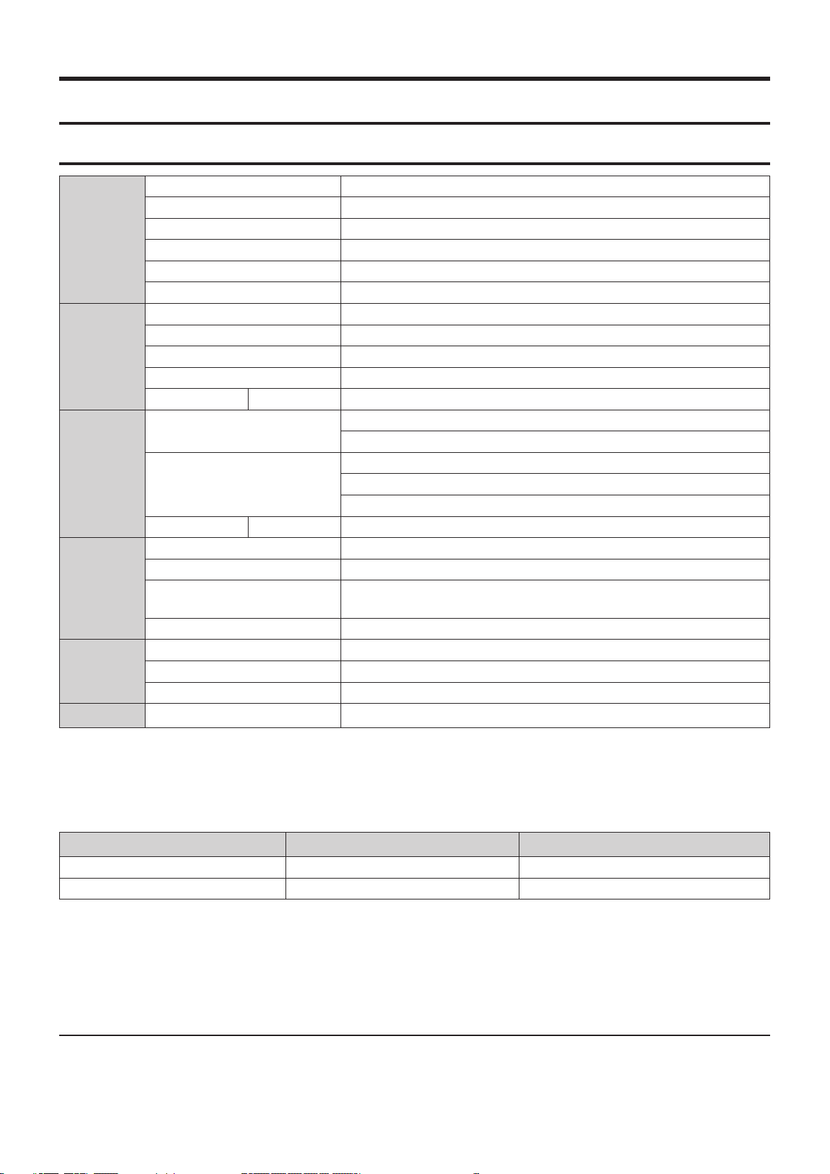
2-1 Product Specication
Power requirements 220-240 V AC, 50 Hz
Power consumption 30 Watts / 2.5 Watts (Power off )
General
Input
Output
Recording
HDD Capac-
ity
USB
Weight 3,8 Kg
Dimensions 430 mm(W) x 300 mm(D) x 55 mm(H)
Operating temp. +5 °C to +35 °C
Other conditions Keep level when operating. Less than 75% operating humidity
Video Composite Video : 1.0 V p-p at 75Ω load, sync negative
Audio Max.Audio Input Level : 2 Vrms
DV Input IEEE 1394(4p) compatible jack
Receivable Channels PAL-B/G, SECAM-L/L', DVB-T
Scart Jack AV2 (Scart Ext) Video : Composite, RGB Audio: analogue
Audio
Video
Scart Jack AV1 (Scart TV) Video : Composite, RGB Audio: analogue
Picture Compression format MPEG-II
Audio Compression format Dolby Digital 2ch/256Kbps, MPEG-II
Recording Quality
Audio Frequency Response 20 Hz~20 kHz
DVD-SH873 160 GB
DVD-SH875 250 GB
DVD-SH877 320 GB
USB 2.0 H/S
Analogue output jacks x 1
Optical/Coaxial digital audio output
Composite Video : Video output jack x 1
Component output x 1 (Y : 1,0Vp-p, Pb : 0,70Vp-p, Pr : 0,70Vp-p at 75Ω load)
HDMI/DVI (576P, 720P,1080i, 1080P)
XP (about 8,5 Mbps), SP (about 4,5 Mbps), LP (about 2,5 Mbps),
EP (about 1,6 Mbps or about 1,2 Mbps)
Host x 1
Audio Output
For DVD discs, audio signals recorded at 96 kHz sampling frequency are converted into and output at 48 kHz.
<Table 2-1>
Disc Type DVD AUDIO CD (CD-DA)
Analogue Audio Output 48 / 96 kHz 44,1 kHz
Digital Audio Output 48 kHz 44,1 kHz
Samsung Electronics 2-1

Product Specication
DVD-SH875 is SAMSUNG 4th DVD/HDD Recorder with Built In Set-Top Box(STB).
Built-in STB Module supply for Digital teresterial Television Reception in European Area.
And DVD-SH853 have HDMI ouput termianl which gives 576 line Progressive , 720 line Progressive ,1080 line
interlace and 1080P line Progressive Digital Video output
- Both Digital Television and also Radio Reception
- Enough Capacity of HARD Disk Drive(HDD)
Video Signal from STB Modeule is inputted as ITU-R BT.656 Digital Component Signal.
So, All the Process of STB video can be processed in Digital Domain for HDMI Video ouput.
-576P,720P,1080i,1080P Standard Denition HDMI Video ouput
-Board Lay-out of DVD-SH875 is rather complex than old model.
It consist of Main ,Jack ,Function ,Front-AV and S.M.P.S 5 PCBs Board Assembly and, DVD-Multi Loader and Hard
Disk Drive.
2-1-1 Maintenance of Cabinet
For safety reasons, be sure to disconnect the AC power cord from the AC outlet.
q Do not use benzene, thinner, or other solvents for cleaning.
q Wipe the cabinet with a soft cloth.
2-1-2 HDD (Hard Disk Drive)
q The hard disk has a high storage density, which enables long recording durations and quick access to written
data. However, it can easily be damaged by shock, vibration or dust and should be kept away from magnets.
To avoid losing important data, observe the following precautions.
q Do not use the HDD & DVD Recorder in a place subject to extreme changes in temperature.
q Do not apply a strong shock to the HDD & DVD Recorder.
q Do not place the HDD & DVD Recorder in a location subject to mechanical vibrations or in an unstable
location.
q Do not place the HDD & DVD Recorder on top of a heat source.
q Do not disconnect the AC power cord while the power is on.
q Do not attempt to change the hard disk. This may result in a malfunction.
Should the hard disk be damaged, you cannot recover lost data. The hard disk is only a temporary storage
space.
2-1-3 Disc Handling
q Use discs with regular shapes. If an irregular disc (a disc with a special shape) is
used, this HDD & DVD Recorder may be damaged.
2-1-4 Disc Speci cations
q This unit allows you to record and playback high quality digital video on DVD-RAM/ W/ discs or on the
HDD.
You can also edit digital images on DVD-RAM/ W discs or HDD.
Disc Type
2-2 Samsung Electronics

<Table 2-2>
FORMAT APPLICATION
A digital versatile disc (DVD) can contain up to 135-minutes of images, 8 audio languages and 32 subtitle languages. It is
equipped with MPEG-2 picture compression and Dolby digital surrounding, allowing you to enjoy vivid and clear theatre
quality images in the comfort of your own home.
DVD-Video
Audio CD
CD-R/-RW
DVD
Disc Play-
back and
Recording
DVD-RW
Disc Play-
back and
Recording
DVD+RW
Disc Play-
back and
Recording
DVD-RAM
Disc Play-
back and
Recording
When switching from the rst layer to the second layer of a dual-layered DVD Video disc, there may be momentary distortion in the image and sound. This is not a malfunction of the unit.
Once a DVD-RW/ recorded in Video Mode is nalised, it becomes DVD-Video.
An audio disc on which 44.1 kHz PCM Audio is recorded.
Plays CD-DA format audio CD-R and CD-RW discs.
The unit may not be able to play some CD-R or CD-RW discs due to the condition of the recording.
Use a 700MB (80 minutes) CD-R/-RW disc. If possible, do not use a 800MB (90 minutes) or above disc, as the disc may not
play back.
If the CD-R/-RW disc was not recorded as a closed session, you may experience a delay in the early playback time, all
recorded les may not play.
Some CD-R/-RW discs may not be playable with this unit, depending on the device which was used to burn them. For contents recorded on CD-R/-RW media from CDs for your personal use, playability may vary depending on contents and discs.
Once a DVD recorded in Video Mode is nalised, it becomes DVD-Video.
You can record onto the available space on the disc and perform editing functions such as giving titles to discs and pro-
grammes and erasing programmes before nalising.
When programming is erased from a DVD , that space does not become available. Once an area on a DVD is recorded on, that area is no longer available for recording, whether the recording is erased or not.
It takes about 30 seconds for the unit to complete recording management information after recording nishes.
This product optimizes the DVD for each recording. Optimizing is carried out when you start recording after inserting the
disc or turning on the unit. Recording onto the disc may become impossible if optimizing is carried out too many times.
Playback may be impossible in some cases due to the condition of recording.
This unit can play back DVD discs recorded and nalised with a Samsung DVD video recorder. It may not be able to
play some DVD discs depending on the disc and the condition of the recording.
Recording and playback can be performed on DVD-RW discs in both the Video and VR Modes.
Once a DVD-RW recorded in both the Video and VR Modes is nalised, you cannot perform additional recording.
Once a DVD-RW recorded in Video Mode is nalised, it becomes DVD-Video.
In both modes, playback can be performed before and after nalisation, but additional recording, deleting and editing can
not be performed after nalisation.
If you want to record the disc in VR Mode and then record in V Mode, be sure to execute Format. Be careful when executing
Format because all the recorded data may be lost.
A DVD-RW blank disc is initialised to VR Mode when rst initialised.
With DVD+RW discs, there is no difference between DVD-Video format(Video mode) and DVD-Video Recording format(VR
mode).
Finalising is generally unnecessary when using a DVD+RW disc.
Ensure that the recording mode is set to VR mode. Otherwise, this product will not be able to play the recording.
You cannot play a DVD-RAM in most DVD components due to compatibility issues.
Only DVD-RAM standard Version 2.0. discs can be played in this unit.
DVD-RAM recorded on this unit may not work with other DVD components. To determine compatibility with these DVD-RAM
discs, refer to the user's manual for the player.
For cartridge type DVD-RAM discs, remove the cartridge and use the disc only.
Product Specication
Samsung Electronics 2-3

Product Specication
2-1-5 Disc Copy
Title Copy Speci cations
<Table 2-3>
Contents HDD DVD DVD HDD
Recorded Video Title Supported Supported
Copy Protected Title Not supported Not supported
Copy Once Title Move (Deletes the Title in the HDD after copying) Not supported
Once "Copy Once programme" has been recorded on the DVD disc, this title cannot be copied to HDD
anymore.
But "Copy Once programme" has been recorded on the HDD, this title can be copied to DVD-RW (VR mode)
with CPRM or DVD-RAM.
Contents Copy Speci cations
<Table 2-4>
Contents HDD DVD or USB DVD HDD or USB USB HDD or DVD
MP3 Supported Supported Supported
JPEG(photo) Supported Supported Supported
DivX Supported Supported Supported
q Disc(CD-R/CD-RW/DVD-RAM, DVD (Finalise)/ DVD+RW/DVD-RW(Finalise)) a HDD or USB
q HDD a DVD-R, DVD-RW(V) or USB
q USB a HDD or DVD-R, DVD-RW(V)
q The disc that has Video recording or has title dubbing from HDD can't be copied.
q PTP USB is not available when you copy to USB.
q If the disc is nalised through Disc Manager, it can be compatible with PC as a disc with a UDF le system.
COPY PROTECTION :
q Many DVD discs are encoded with copy protection.
q This product incorporates copyright protection technology that is protected by methods claims of
certain U.S. patents and other intellectual property rights owned by Macrovision
Corporation and other rights owners. Use of this copyright protection technology must be authorised by
Macrovision Corporation, is intended for home and other limited viewing uses only unless
otherwise authorised by Macrovision Corporation. Reverse engineering or disassembly is prohibited.
2-1-6 HDD Model specication
<Table 2-5>
SPEC.
Area Category Model
DVD-SH870 160G X
DVD-SH873 160G O X O O O
France
(XEF)
"UK
(XEU)"
DVB-T
DVB-T
DVD-SH874 160G O X O O O
DVD-SH875 250G O X O O O
DVD-SH876 250G O X O O O
DVD-SH877 320G O X O O O
DVD-SH871M 160G
DVD-SH873M 160G O O O O O
DVD-SH875M 250G O O O O O
DVD-SH876M 250G O O O O O
HDD
"Full Multi
(±R Dual)"
O O O O X
Tuner MHEG
X X O X
"DVB-T/
Analog"
"HDMI
1080p"
DV1394 USB2.0
2-4 Samsung Electronics
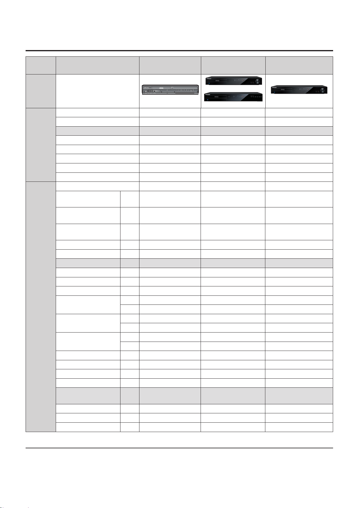
2-2 Chassis Product Specication
Product Specication
General Model Name DVD-SH853
Chassis
Design (Type Name) VR-7253 VR7253 VR7253
Remocon Code AK59-00062D AK59-00079B AK59-00079B
Button 53Key 60Key 60Key
REMOTE
CON-
TROLLER
TERMI-
NALS
(Input/Out-
put)
Battery Type AAA AAA AAA
Body Color Black Black Black
Language English English English
Multi-Brand TV Control Yes Yes Yes
Illuminated Button - - -
Input Select (AV1/AV2/AV3/DV/PR) AV1/AV2/AV3/DV/PR AV1/AV2/AV3/DV/PR AV1/AV2/AV3/DV/PR
Scart Jack-1 A/V Input/
Output
RGB Output with Scart
AV 1
Scart Jack-2 A/V with RGB
Input
CVBS Output - RCA Jack Rear x1 x1 x1
Audio Output -RCA Jack Rear x1 ( L,R) x1 ( L,R) x1 ( L,R)
S-Video Output Rear x1 - -
Component Video out Rear x1(Y,Pb,Pr) x1(Y,Pb,Pr) x1(Y,Pb,Pr)
Digital Audio Out (Optical) Rear x 1 x1 x1
Digital Audio Out (Coaxial) Rear x 1 x1 x1
CVBS Input - RCA Jack
Audio Input -RCA Jack
S-Video Input
DV Input Front x1 x1 x1
Aerial Input Rear x1 x1 x1
RF Out Rear x1(w/o Modulator) x1(w/o Modulator) x1(w/o Modulator)
HDMI Output Rear x1 x1 x1
USB2.0 Mass Storage
Host
USB2.0 PictBridge Slave Front - - -
Built-In Bluetooth Front - - -
Memory Card Slot Front - - -
Rear AV1 AV1 AV1
Rear Yes Yes Yes
Rear AV2 AV2 AV2
Rear - - -
Front x1(AV3) x1(AV3) x1(AV3)
Rear - - -
Front x1 ( L,R / AV3) x1 ( L,R / AV3) x1 ( L,R / AV3)
Rear - - -
Front - - -
Front x1 855, 857, 855M, 857M Yes Yes
DVD-SH873/SH875/
SH877, SH874/SH876
(DVD-SH873/SH875/SH877)
(DVD-SH874/SH876)
DVD-SH873M/SH875M/
SH877M
Samsung Electronics 2-5

Product Specication
General Model Name DVD-SH853
Chassis
DVD-video Yes Yes Yes
DVD-RAM Yes Yes Yes
DVD-RW Yes Yes Yes
DVD-R Yes Yes Yes
DVD+RW Yes Yes Yes
DVD+R Yes (w/o Logo) Yes Yes
VCD Yes (w/o Logo) - -
SVCD Yes - -
PLAY-
ABLE
MEDIA &
FORMAT
MPEG4 (DivX3.1/DivX 4/DivX
5/DivX6)
Yes Yes Yes
DVD-Audio - - -
SACD - - -
CD Yes Yes Yes
MP3 Yes Yes Yes
JPEG Yes(1000Folder) Yes(1000Folder) Yes(1000Folder)
WMA - - -
MIDI / SEMI - KARAOKE - - -
Memory Card - - -
Hard Disc (HDD) Yes Yes Yes
DVD-RAM Yes Yes Yes
DVD-RW Yes Yes Yes
DVD-R Yes Yes Yes
RECORD-
ING Disc
Media
DVD+RW - Yes Yes
DVD+R - Yes Yes
CD-R/-RW - - -
DUAL LAYER RECORDING -R only -R only / Yes / Yes -R only / Yes
Hard Disc (HDD) Yes Yes Yes
VIDEO MPEG-2 MPEG-2 MPEG-2
AUDIO 2ch 2ch 2ch
Recording
Format
DVD-Video Yes Yes Yes
MPEG4 - - -
RGB Recording Yes Yes Yes
CD-DA - - -
MODE XP/SP/LP/EP/SEP XP/SP/LP/EP/SEP XP/SP/LP/EP/SEP
RECORD-
ING TIME/
MODE
Drive Speed x2 x2 x2
MPEG2 (XP/SP/LP/EP) 1/2/4/8 1/2/4/8 1/2/4/8
Quick Dubbing (x4 Speed) Yes Yes Yes
DVD-SH873/SH875/
SH877, SH874/SH876
(DVD-SH873/SH875/SH877)
(DVD-SH874/SH876)
DVD-SH873M/SH875M
2-6 Samsung Electronics

Product Specication
General Model Name DVD-SH853
Chassis
VIDEO (NTSC3.58) REC/PB No/NTSC3.58 No/Q-PAL No/Q-PAL
(NTSC4.43) REC/PB No / No No / No No / No
(PAL) REC/PB Yes / Yes Yes / Yes Yes / Yes
COLOR
SYSTEM
(PAL-M) REC/PB No / No No / No No / No
(PAL-N) REC/PB No /No No / No No / No
(SECAM) REC/PB PAL Recording&Playback PAL Recording & Playback PAL Recording & Playback
(MESECAM) REC/PB No / No No/No No / No
Broadcast System SECAM-L/L', PAL-B/G SECAM-L/L', PAL-B/G PAL - I
Audio ( Stereo System ) A2/NICA A2/NICAM A2/NICAM
Number of Preset(Station Capacity) 99 99 99
Tuning System Intelligent Auto Set-up Intelligent -Auto Set Up Intelligent -Auto Set Up
CH Coverage VHF / UHF / CATV VHF/UHF/CATV VHF/UHF/CATV
RF(Modulator) Out CH & System - - -
TUNER
Default RF Out Channel - - -
Auto CH Sorting & Mapping Yes Yes Yes
Station Name Display Auto Detect Auto Detect Auto Detect
Digital (DVB-T) Yes Yes Yes
Digital (DVB-S) - - -
Digital BS - - -
TIMER
PRO-
GRAM-
MING
Number of Events (Programming
No)
Gemstar ( G-CODE/ShowView/
VideoPlus+)
VPS / PDC Yes Yes Yes
12Events / Month 12Events / Month 12Events / Month
Yes Showview VideoPlus+
SI-EPG (Digital) - Yes Yes
OTR (Instant Recording Timer) OFF,0:30,1:00,~ 8:00 OFF,0:30,1:00,~ 8:00 OFF,0:30,1:00,~ 8:00
Back-Up Type & Time EEPROM / Permanent EEPROM / Permanent EEPROM / Permanent
CLOCK
Clock Type Quartz Quartz Quartz
Auto Clock Setting Yes Yes Yes
Video DAC 10bit/54MHz 10bit/54MHz 10bit/54MHz
Progressive Scan Output Yes Yes Yes
Component Video Output Yes Yes Yes
VIDEO
OUTPUT
RGB Output with Scart AV 1
Yes Yes Yes
HDMI Output Yes Yes Yes
HDMI - Upscaling(720P/1080i/
1080P)
Yes / Yes / No Yes Yes
DVD-SH873/SH875/
SH877, SH874/SH876
(DVD-SH873/SH875/SH877)
(DVD-SH874/SH876)
DVD-SH873M/SH875M
Samsung Electronics 2-7

Product Specication
General Model Name DVD-SH853
Chassis
Audio DAC 24bit/96kHz 24bit/96kHz 24bit/96kHz
Dolby Digital Out Yes Yes Yes
AUDIO
OUTPUT
DTS Digital Out Yes Yes Yes
PCM / Bit Stream Yes / Yes Yes / Yes Yes / Yes
MPEG-1/2
Yes / Yes Yes / Yes Yes / Yes
Custom A/V Mode - - -
Play List Playback Yes Yes Yes
FR(Auto) MODE for Timer Rec Yes Yes Yes
Automatic Chapter Creation
Yes(XP/SP:5Min,LP/
EP:15Min)
Scan Search (DVD-RAM/-R/-RW) 2/4/8/16/32/128 2/4/8/16/32/128 2/4/8/16/32/128
Slow Speed 1/8,4,2 1/8,4,2 1/8,4,2
Step ( Forward / Reverse ) Yes Yes Yes
ZOOM Yes(x2,x4) Yes(x2,x4) Yes(x2,x4)
Resume Playback Yes(1Disc) Yes(1Disc) Yes(1Disc)
x1.5 Playback with Audio
Yes Yes Yes
Repeat(Title/Chapter/A-B) Yes Yes Yes
PLAY-
BACK
RECORDING FEA-
TURES
Marker Yes Yes Yes
Closed Caption - - -
Black Level Select ( PAL : OFF ) - - -
CM Skip - - -
Book Mark Yes Yes Yes
Custom Parental Control Yes Yes Yes
Time Slip Yes Yes Yes
Quick Dubbing (x4 Speed) Yes Yes Yes
EZ Editing Yes Yes Yes
Music Slide Show(Authoring) - Yes Yes
Enhaced Video Quality (EVQ) Yes Yes Yes
Child Door lock for DVD Tray - - -
Time Shift Yes Yes Yes
EZ Record mode Yes Yes Yes
HDMI CEC Yes Yes Yes
DVD-SH873/SH875/
SH877, SH874/SH876
(DVD-SH873/SH875/SH877)
(DVD-SH874/SH876)
Yes(XP/SP:5Min,LP/
EP:15Min)
DVD-SH873M/SH875M
Yes(XP/SP:5Min,LP/
EP:15Min)
2-8 Samsung Electronics

Product Specication
General Model Name DVD-SH853
Chassis
Capacity 160G 160G / 250G / 320G 160G
Plate Size 3.5" 3.5" 3.5"
Recording Time(EP 8HR Mode) About 270Hr
VR PAL PAL PAL
HDD Playback
MP3 Yes Yes Yes
JPEG Yes Yes Yes
DivX Yes Yes Yes
HDD
Copy HDD-> DVD
VIDEO
JPEG Yes Yes Yes
Yes Yes Yes
MP3 Yes Yes Yes
DivX Yes Yes Yes
Copy DVD-> HDD
VIDEO
JPEG Yes Yes Yes
Yes Yes Yes
MP3 Yes Yes Yes
DivX Yes Yes Yes
Middleware FTA FTA FTA/MHEG
RS-232C(DTT Upgrade) No (CD upgrade) No (CD upgrade) No (CD upgrade)
Timer Recording/Timer Watching Yes / No Yes / No Yes / No
SI-EPG - Yes Yes
TTX (VBI / OSD) Yes Yes Yes
LCN Yes Yes Yes
Caption Yes Yes Yes
Auto ch scan Yes Yes Yes
Manual ch scan Yes Yes Yes
DTT
Favorite Channel Yes Yes Yes
Parental Guide Yes Yes Yes
Channel List Yes Yes Yes
Change PIN Code Yes Yes Yes
STB Radio Yes Yes Yes
MHEG Yes No Yes
CI - No No
MHP - No No
CAS - No No
OTA Yes Yes Yes
DVD-SH873/SH875/
SH877, SH874/SH876
(DVD-SH873/SH875/SH877)
(DVD-SH874/SH876)
About 264Hr / About 421Hr
/ About 534Hr
DVD-SH873M/SH875M
About 264Hr
Samsung Electronics 2-9
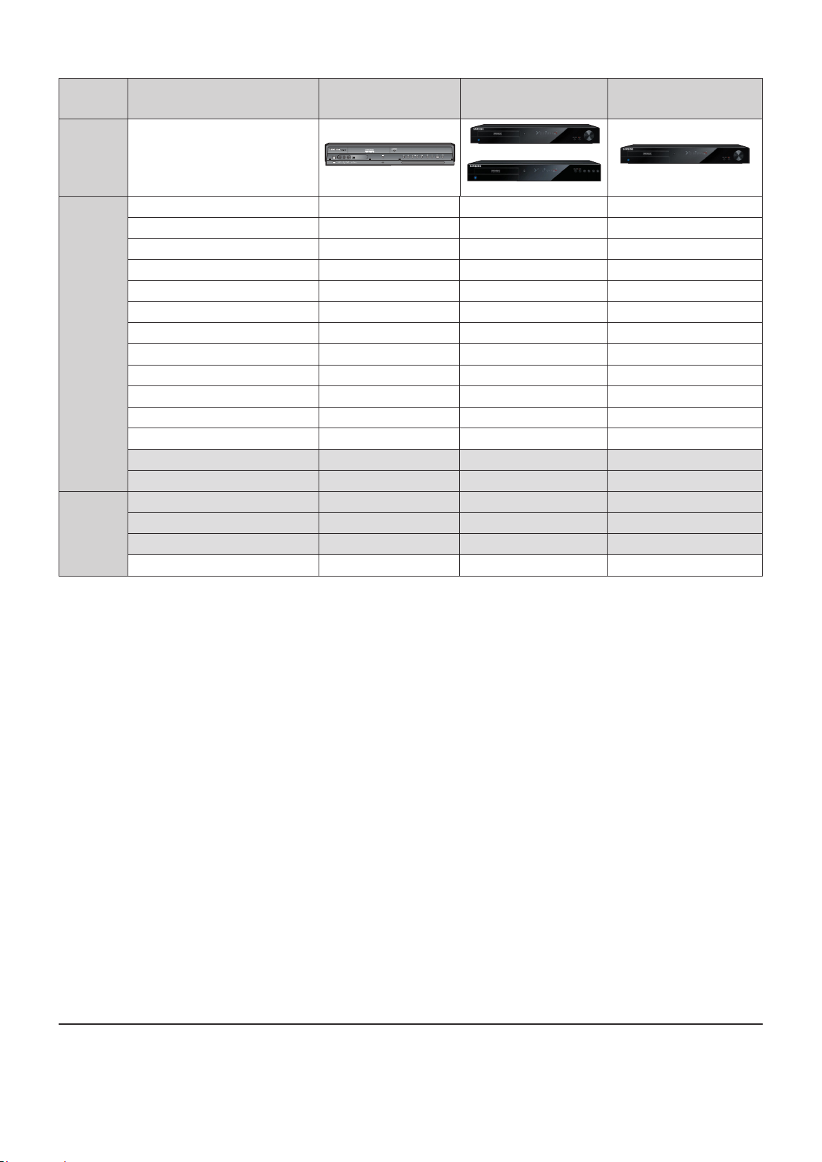
Product Specication
General Model Name DVD-SH853
Chassis
Remote Controller Yes Yes Yes
Batteries Yes(x2) Yes(x2) Yes(x2)
AV Cable (RCA Type) Yes Yes Yes
RF Cable Yes Yes Yes
Euro Scart Cable - - -
HDMI - HDMI Cable - - -
ACCES-
SORY
HDMI - DVI Cable - - -
User's Manual (Instruction Manual) Yes Yes Yes
Quick Start Guide Yes Yes Yes
DISC ( Bundle ) - - -
Customer Request Card - - -
Product Registration Card Yes Yes Yes
AS LIST
Yes (combined in I/B) - Yes
Warranty Card 5 Digit LED Yes (combined in I/B) Yes (combined in I/B)
Display of Front Panel Blue VFD VFD
Power LED Red Blue Blue
DISPLAY
REC LED Yellow in VFD in VFD
HDD/DVD LED Green Green Green
DVD-SH873/SH875/
SH877, SH874/SH876
(DVD-SH873/SH875/SH877)
(DVD-SH874/SH876)
DVD-SH873M/SH875M
2-10 Samsung Electronics

2-3 Option Product Specication
Description Fig Description Parts No Remark
Product Specication
Remote
Control
Batteries for
Remote Control
User's Manual AK68-01581A
Quick Guide AK68-01593A
AK59-00079B
4301-001035
Model Standard of
DVD-SH875/XEF
Model Standard of
DVD-SH875/XEF
S.N.A
Model Standard of
DVD-SH875/XEF
Model Standard of
DVD-SH875/XEF
S.N.A
Video/Audio
Cable
RF Cable AC39-00017A
Samsung Electronics 2-11
AC39-42001R
Model Standard of
DVD-SH875/XEF
Model Standard of
DVD-SH875/XEF

Product Specication
M E M O
2-12 Samsung Electronics

3. Disassembly and Reassembly
3-1 Cabinet and PCB
Note : Reassembly in reverse order.
3-1-1 Top Cabinet Removal
1) Remove 5 Screws q, w, e.
2) Lift up the Top Cabinet r in direction of arrow.
e 1 SCREW
(3X10 B)
q 3 SCREWS
(3X10 B)
r TOP CABINET
w 1 SCREW
(3X8 B)
Fig. 3-1 Top Cabinet Removal
Samsung Electronics 3-1

Disassembly and Reassembly
3-2 Samsung Electronics
3-1-2 Ass'y Front-Cabinet Removal
1) Release 7 Hooks q, w, e, r and Ass'y Front-Cabinet t.
q 1 HOOK
r 3 HOOKS
e 2 HOOKS
w 1 HOOK
t ASS'Y FRONT-CABINET
Fig. 3-2 Ass'y Front-Cabinet Removal

3-1-3 Hard Disk Removal
1) Remove 4 Screws q, w from the Ass'y Hard Disk e and lift it up.
w 2 SCREWS
q 2 SCREWS
(32UNC x 4.2 W)
(32UNC x 4.2 W)
Disassembly and Reassembly
e ASS'Y HARD DISK
Fig. 3-3 Hard Disk Removal
Samsung Electronics 3-3

Disassembly and Reassembly
3-4 Samsung Electronics
3-1-4 Ass'y Deck Removal
1) Remove 4 Screws q, w from the Ass'y Deck e and lift it up.
w 2 SCREWS
q 2 SCREWS
(3X10 W)
(3X10 W)
w ASS'Y DECK
Fig. 3-4 Ass'y Deck Removal
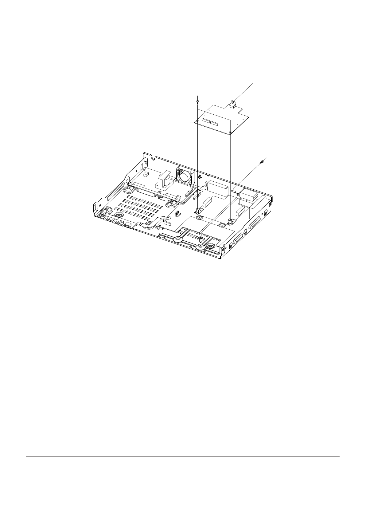
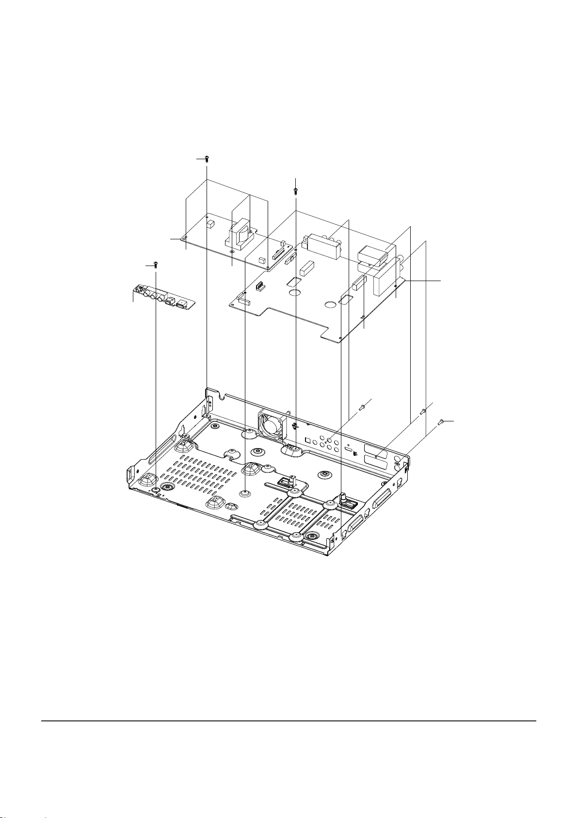
3-1-5 Main PCB Removal
1) Remove 3 Screws q, w from the Main PCB e and lift it up.
w 2 SCREWS
(3X10 W)
e MAIN PCB
Disassembly and Reassembly
q 1 SCREW
(3X10 B)
Fig. 3-5 Main PCB Removal
Samsung Electronics 3-5
Disassembly and Reassembly
3-6 Samsung Electronics
3-1-6 Jack PCB, S.M.P.S PCB and Front PCB Removal
1) Remove 8 Screws q, w, e, r from the Jack PCB t and lift it up.
2) Remove 5 Screws y from the S.M.P.S PCB u and lift it up.
3) Remove 1 Screw i from the Front PCB o and lift it up.
y 5 SCREWS
u S.M.P.S PCB
i 1 SCREW
(3X6 W)
o FRONT PCB
(3X6 W)
q 5 SCREWS
(3X6 W)
w 1 SCREW
(3X10 B)
t JACK PCB
e 1 SCREW
(3X10 B)
r 1 SCREW
(3X10 B)
Fig. 3-6 Jack PCB, S.M.P.S PCB and Front PCB Removal

3-2 PCB Location
MAIN PCB
Disassembly and Reassembly
JACK PCB
S.M.P.S PCB
FRONT PCB
Fig. 3-7 PCB Location
Samsung Electronics 3-7

Disassembly and Reassembly
M E M O
3-8 Samsung Electronics

4. Trouble Shooting
4-1 Trouble Shooting -------------------------------------------------------------------------------- 4-2
4-2 Software Update ------------------------------------------------------------------------------- 4-46
Samsung Electronics 4-1

Trouble Shooting
4-1 Trouble Shooting
NO Power Detected
(Stand by LED OFF)
FIS01 is normal?
Yes
Is
there
voltage at "t" pin
of CIS01?
Yes
ZDIS01,
ZDIS02 SHORT and
OPEN
Are normal?
Yes
Is there
voitage at pin "1"(Draing)of
ICIS01
No
No
No
No
Change fuse
Check D01~D04 or RIS04
Change short circuited or
opened parts
Check 2st voltage
Check 1st short circuited
or opened parts
Yes
Operation
of ICIS01 is
Normal?
Yes
Check feedback IC1S02
Refer to a pattern
image of Table 4-1
Replace ICIS01
4-2 Samsung Electronics
 Loading...