

Samsung DVDHR-720 Service manual
Introducing Samsung DVD Recorder
Introducing Samsung DVD Recorder
( DVD-HR720)
( DVD-HR720)
Samsung Electronics Co. LTD
Digital Video Division

What is SEC’s DVD-HR720?
Digital A/V system for video playing & recording
Digital A/V system for video playing & recording
using optical disc as the medium format
using optical disc as the medium format
High-quality Recording
Optical Medium and HDD
Recording
Digital recording by an optical
High picture and sound quality
medium and HDD format allows
recording capability comparing
random access capability and easy
with analog medium recording
& convenient recording
systems
2

Samsung HDD-DVD Recorder
General Introduction
❏
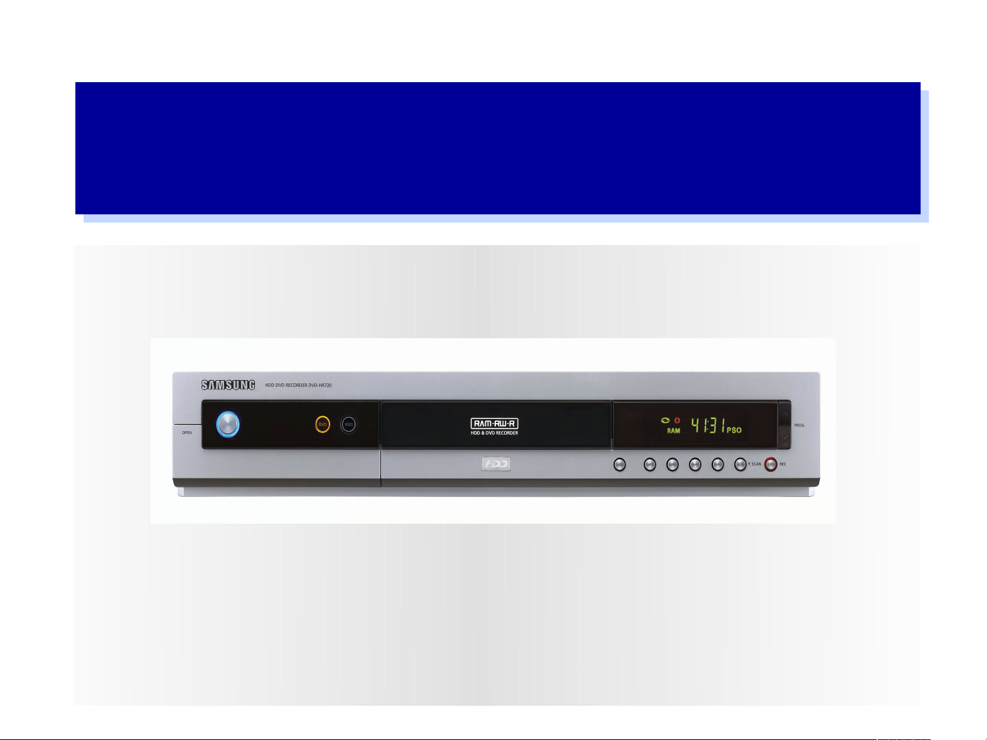
Model No : DVD-HR720
Characteristics
1. Super picture & sound quality recording with MPEG-2(VBR) on DVD-RAM,
compatible with A/V & PC
2. Convenient control through random accessibility of optical discs & HDD disc
- One touch recording : Automatic empty area recording
- High Speed Search and Play
3. Qui ck dubbi ng : Wi t h t he qui ck dubbi ng f unct i on, dat a t r ans f er f r om
HDD t o DVD Di s c i s f as t er t han ever
4. Advanced playback functions for multiple purposes
(Compatible with DVD, Audio-CD, CD-R/RW(MP-3,MPEG4), DVD-R, DVD-RW,DVD-RAM
HDD Disc)
3

DVD-HR720 Playback & other Features
■ Progressive Scan
By scanning all 576 lines(PAL) in one pass,
progressive scanning provides high vertical
resolution and flicker-free, high-density image
output that does not suffer from the loss of
quality during subject movement -- which is
characteristic of the conventional interlaced
scanning method.
■ Program Navigator
50 Frame/Sec25 Frame/Sec
Recorded programs are shown as thumbnail pictures, and information
such as title, recording dates and times are displayed on menu screen.
User can choose a desired program.
■ Editing
Simple non-linear editing is possible on menu screen without additional editing
system. User can delete part of a program or entire program, and edit program title.
4

Assembly
DVD-HR720 consists of Deck, Main PCB, Jack PCB, SMPS PCB,
HDD, Top, Bottom, Panel Ass’y.
M ain P CB
Jack P C B
P ane l
A s s 'y
D eck A ss 'y
T op
M ain P CB
B otto m
A s s'y

Di s as s embl y and Reas s embl y
pr oces s
Adobe Acrobat
¹®¼

Supplide Accessary
: DVD-HR720 supply below accessary
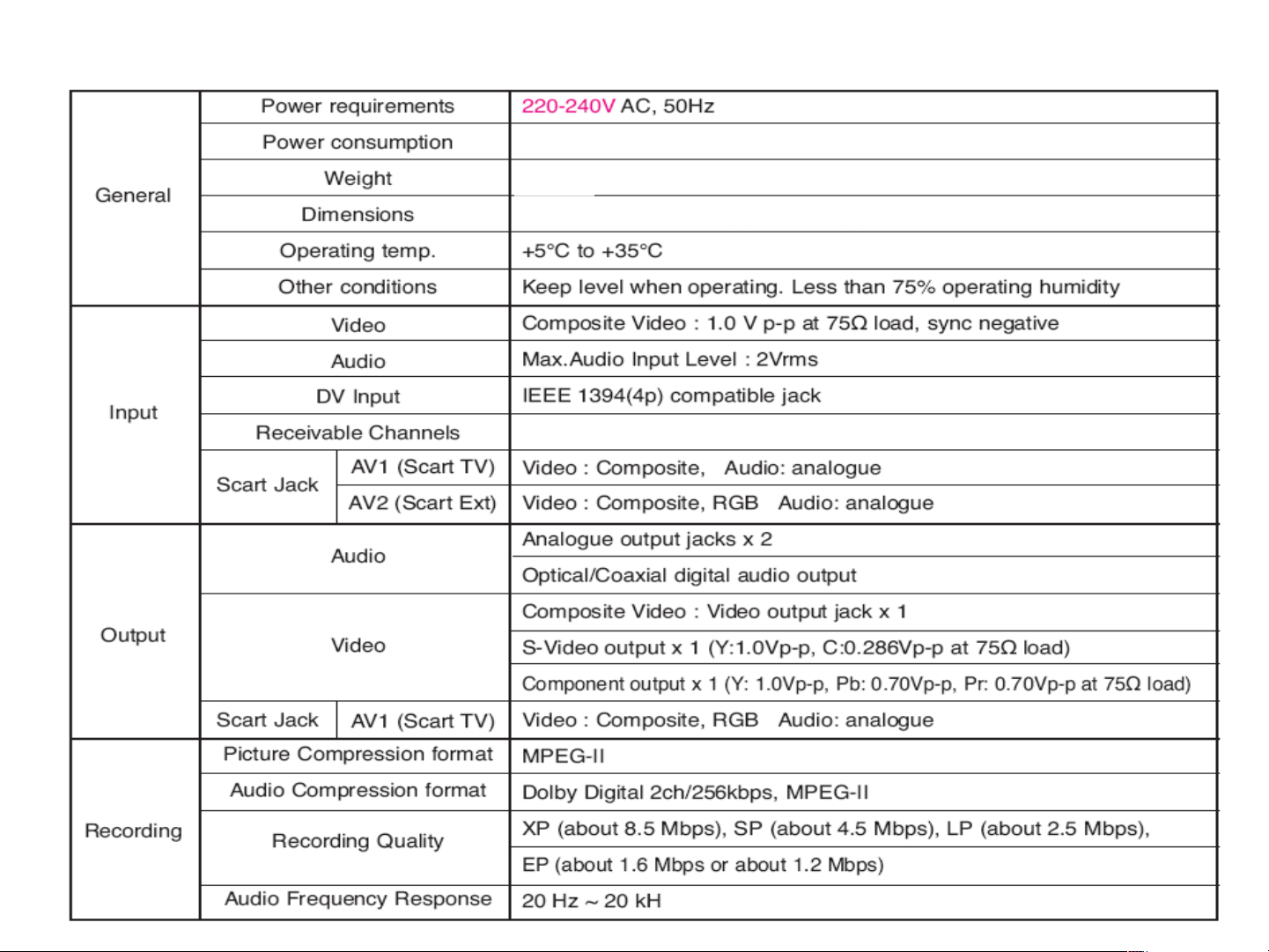
Specifications
6. 7 Wat t t s ( st and by ) , 31 Wat t t s ( s t and by on) , 45 Wat t t s ( Rec & Pl ay s i mul t aneus l y)
4. 2 Kg
430mm( W) × 255mm( D) × 79mm( H)
PAL B/ G, I , D/ K SECAM L/ L’

DVD-HR720 Key Features
Recording Features
■ MPEG-2 VBR(Variable Bit Rate) Recording
■ Creating a DVD video title using DVD-RW/DVD-R
■ One-Touch Recording
■ Automated Quality Adjustment for Timer Recording
■ Copying data from a digital camcorder using a DV input jack
■ Selectable Recording Mode
Playing Features
■ Progressive Scan
■ Program Navigation
Other Features
■ Easy Editing
9
■ Aut o Chapt er i ng
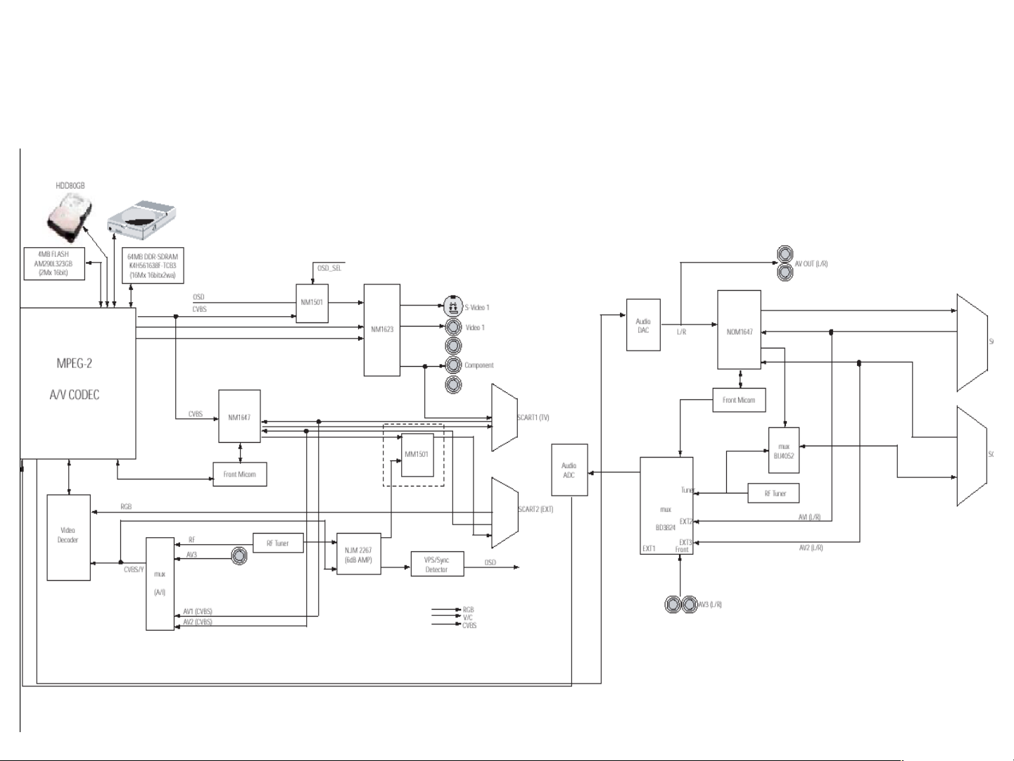
1. Overall block diagram
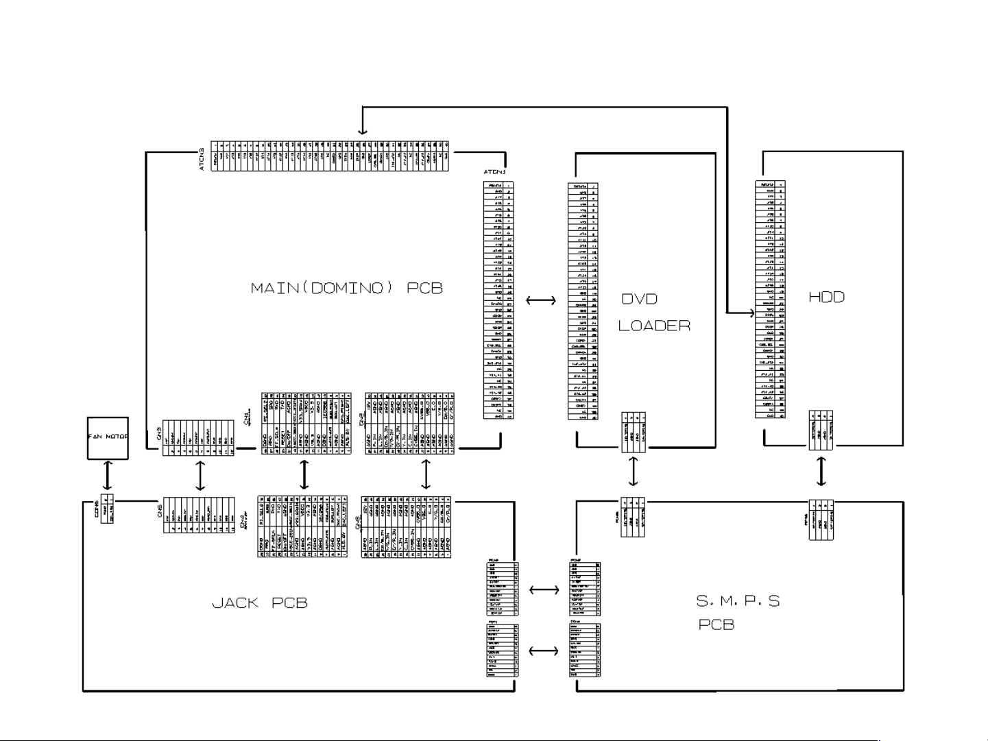
2. Wiring diagram

2. DOMINO H/W
I nt er f ace
■ HOST Interface
■ Per i pher al / St or ag e
I nt er f ac e
■ ATAPI Cont r ol l er
( Mas t er : HDD, Sl ave :
ODD)
■ I EEE 1394 I nt er f ac e
■ Vi deo I nt er f ace
DMN8652
■ Audi o I nt er f ace
■ SDRAM I nt er f ac e
■ Ser i al I / O I nt er f ace
■ UART I nt er f ace

3. Front-Micom I nt er f ace
•
Front- Micom UD78F4928GF(FIC1, NEC) is used to control
Power, LED Module, MTS Block, VPS/PDC, KEY Input Matrix
etc.
•
The SPI (Serial Peripheral Interface) port provides a bus
for a serial interface with AV- CODEC DMN8652(DIC1)

4. Vi deo I nput I nt er f ace
•
DVD- HR720 has the one RCA Video
input and two SCART Jack.
•
1 RGB Input, 1 CVBS in Scart jack
•
1 RCA input in Front Panel .
•
The analog Video signal be selected Line 1 or Line 2 by the FIC1 (Front Micom:Control part)
and IC201(MUX IC;Switching part).
•
TIC1 (Video Decoder) diverges from the 14.318185MHz crystal, then generates ITU- R656
(10bits) and 27MHz clock.
•
TIC1 (Video Decoder) does closed caption, copy guard detect processing and A/D conversion
of analog Video signal converted into 10bit Digital Video signal (ITU- R656 Format) is
outputted via DIC1 (MPEG2 Decoder & Encoder with video Encoder:DMN8602) of digital part.

5. Anal og MUX( BU4052)
IC201 is analog MUX. As Pin 9, 10 of the IC201 are controlled by the Front
Micom, IC201 select Line1 of CVBS[Pin14], Line2 of CVBS[Pin 15] and RF
signal.
The analog Video Signal of IC201 & IC202 output is selected by the FIC1 via
TIC1(Video Decoder : TVP5146) of analog Video input parts.

6. NTSC/ PAL Vi deo DECODER
Video DECODER TVP5146 (TIC1) is a high quality
NTSC, PAL, and SECAM video decoder plus YPbPr
component inputs designed for multimedia
applications.
This TIC1 (Video Decoder) includes three 10- bit
high speed ADCs.converters. and A/D conversion of
10bit analog Video signal converted into Digital
Video signal (ITU- R656 Format) is outputted via
On CVBS and S- video inputs, the user can control
video characteristics such as contrast, Brightness,
saturation, and hue via an I2C DIC1 port interface.
A built- in versatile VBI slicer and VBI data passthrough capability support common data services.
 Loading...