

Samsung DV56H9000GW/A2-00, DV56H9000GP/A2-00, DV56H9000EW/A2-00, DV56H9000EP/A2-00 Owner’s Manual
D
Thank you for purchasing this Samsung product.
To receive more complete serwce or accessory
parts, please register your product at or contact
www.samsung.com/register
1-800-SAMSUNG (726-7864)
INSTALLING YOUR DRYER
7 Unpacking your dryer
/'
/
7 Basic requirments
8 Ducting requirements
9 Important to installer
9 Location considerations
9 Alcove or closet installation
10 Exhausting
11 Gas requirements
11 Commonwealth of Massachusetts
installation instructions
12 Electrical requirements
12 Grounding
13 Electrical connections
14 Installation - General procedure
17 Connecting the Inlet Hose
17 Final installation check list
18 Dryer Exhaust Tips
19 Door Reversal
OPERATING INSTRUCTIONS, TIPS
OPERATING INSTRUCTIONS, TIPS
OPERATING INSTRUCTIONS, TIPS
CARE AND CLEANING
SPECIAL LAUNDRY TIPS
TROUBLESHOOTING
21 Overview of the control panel
24 Rack Dry
25 My Cycle
i
i
25 Drum Light
25 Sound
25 Child lock
26 Smart Care
27 Clean the lint filter
27 Load the dryer properly
27 Getting started
27 Vent sensor
29 Control Panel
29 Tumbler
29 Powder Coated Tumbler
29 Dryer Exterior
29 Dryer Exhaust System
30 Special laundry tips
31 Check these points if your dryer.,.
32 Information codes
APPENDIX
33 Fabric care chart
34 Protecting the environment
34 Declaration of conformity
34 Specifications
35 Cycle chart
Engl sh - 2
Congratulations on your new Samsung Dryer. This manual contains valuable
information on the installation, use, and care of your appliance. Please take the
time to read this manual to take full advantage of your dryer's many benefits and
features.
WHAT YOU NEED TO KNOW ABOUT SAFETY INSTRUCTIONS
Warnings and Important Safety Instructions in this manual do not cover all possible conditions and
situations that may occur. It is your responsibility to use common sense, caution, and care when installing,
maintaining, or operating your dryer.
Always contact your manufacturer about problems or conditions you do not understand.
IMPORTANT SAFETY SYMBOLS AND PRECAUTIONS
What the icons and signs in this user manual mean:
Hazards or unsafe practices that may result in severe personal injury
or death.
/k
WARNING
Z_ Hazards or unsafe practices that may result in minor personal injury or
CAUTION property damage.
Follow the information in this manual to minimize the risk of fire or
explosion or to prevent property damage, personal injury, or death.
Do not store or use gasoline or other flammable vapors and liquids near
this or any other appliance.
Do NOT attempt.
[_ Do NOT disassemble.
[_ Do NOT touch.
Follow directions explicitly.
Unplug the power plug from the wall socket.
Make sure the machine is grounded to prevent electric shock.
Call the service center for help.
Note
These warning icons are here to prevent injury to you and others.
Please follow them explicitly.
After reading this section, keep it in a safe place for future reference.
_Read all instructions before the
using appliance.
Engl sh - 3
WARNING: To reduce the risk of fire, electric shock, or injury to persons when using your
A
WARNING
appliance, follow basic precautions, including the following:
1. Read all instructions before using this appliance.
2. Do not dry articles that have been previously cleaned in, washed in, soaked in,
or spotted with gasoline, dry-cleaning solvents, or other flammable or explosive
substances, as they give off vapors that could ignite or explode.
3. Do not use the dryer to dry clothes which have traces of any flammable substance,
such as vegetable oil, cooking oil, machine oil, flammable chemicals, paint thinner, etc.,
or anything containing wax or chemicals, such as mops and cleaning cloths. Flammable
substances may cause the fabric to catch fire by itself.
4. Do not store or use gasoline or other flammable vapors and liquids near this or any
other appliance.
5. Do not allow children to play on or in the appliance. Close supervision of children is
necessary when the appliance is used near children.
6. Before the appliance is removed from service or discarded, remove the door to the
drying compartment.
7. Do not reach into the appliance if the drum is moving.
8. Do not install or store this appliance where it will be exposed to the weather.
9. Do not tamper with internal controls.
10. Do not repair or replace any part of the appliance or attempt any service unless
specifically recommended in the user-maintenance instructions or in published user-
repair instructions that you understand and have the skills to carry out.
11. Do not use fabric softeners or products to eliminate static unless recommended by the
manufacturer of the fabric softener or product.
12. Clean the lint screen before or after each load.
13. Do not use heat to dry articles containing foam rubber or similarly textured rubber-like
materials.
14. Keep area around the exhaust opening and adjacent surrounding areas free from the
accumulation of lint, dust, and dirt.
15. The interior of the appliance and exhaust duct should be cleaned periodically by
qualified service personnel.
16. Do not place items exposed to cooking oils in your dryer. Items contaminated with
cooking oils may contribute to a chemical reaction that could cause a load to catch fire.
17. This appliance must be grounded. See "Electrical requirements" and "Grounding" in
installing your dryer section.
18. Do not allow children to play on or in the appliance. Close supervision of children is
necessary when the appliance is used near children.
19. Do not insert your hand under the dryer.
- This may result in injury.
20. Take care that children's fingers are not caught in the door when closing it.
- This may result in injury.
Engl sh - 4
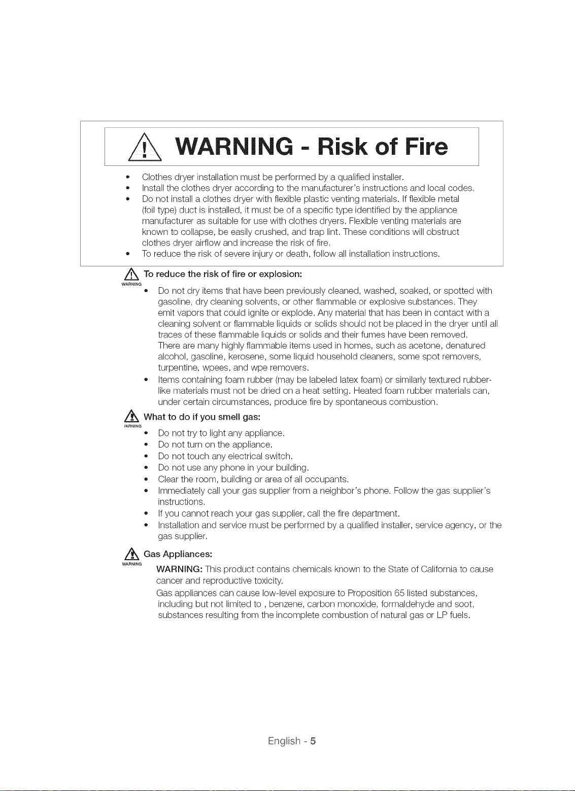
WARNING --Risk of Fire
,, Clothes dryer installationmust be performed by a qualified installer.
Install the clothes dryer according to the manufacturer's instructions and local codes.
,, Do not install a clothes dryer with flexible plastic venting materials. Ifflexible metal
(foil type) duct is installed, it must be of a specific type identified by the appliance
manufacturer as suitable for use with clothes dryers. Flexible venting materials are
known to collapse, be easily crushed, and trap lint. These conditions will obstruct
clothes dryer airflow and increase the risk of fire.
To reduce the risk of severe injury or death, follow all installation instructions.
/_To
WARNING
reduce the risk of fire or explosion:
®
Do not dry items that have been previously cleaned, washed, soaked, or spotted with
gasoline, dry cleaning solvents, or other flammable or explosive substances. They
emit vapors that could ignite or explode. Any material that has been in contact with a
cleaning solvent or flammable liquids or solids should not be placed in the dryer until all
traces of these flammable liquids or solids and their fumes have been removed.
There are many highly flammable items used in homes, such as acetone, denatured
alcohol, gasoline, kerosene, some liquid household cleaners, some spot removers,
turpentine, wpees, and wpe removers.
Items containing foam rubber (may be labeled latex foam) or similarly textured rubber-
like materials must not be dried on a heat setting. Heated foam rubber materials can,
under certain circumstances, produce fire by spontaneous combustion.
/f_ What to do if you smell gas:
IARNING
Do not try to lightany appliance.
Do not turn on the appliance.
,, Do not touch any electrical switch.
Do not use any phone in your building.
Clear the room, building or area of all occupants.
Immediately call your gas supplier from a neighbor's phone. Follow the gas supplier's
instructions.
,, Ifyou cannot reach your gas supplier, call the fire department.
,, Installation and service must be performed by a qualified installer, service agency, or the
gas supplier.
_ Gas Appliances:
WARNING
WARNING: This product contains chemicals known to the State of California to cause
cancer and reproductive toxicity.
Gas appliances can cause low-level exposure to Proposition 65 listed substances,
includingbut not limitedto, benzene, carbon monoxide, formaldehyde and soot,
substances resulting from the incomplete combustion of natural gas or LP fuels.
Engl sh - 5
Do not allow children or pets to play on, in, or in front of the appliance. Close supervision is
necessary when the appliance is used near children and pets.
Before discarding or removing your dryer from service, remove the door to the drying
compartment to prevent children or animals from becoming trapped inside.
Do not reach into the appliance when the drum is moving.
Do not install or store this appliance where it will be exposed to the weather.
Do not tamper with controls.
Do not repair, replace, or attempt to service any part of the appliance unless specifically
instructed to in the user-repair instructions and you have the understanding and skills to
carry out the procedure.
Do not use fabric softeners or products to eliminate static unless the softener or product is
recommended for dryer use by the manufacturer of the fabric softener or product.
Clean the lint screen before or after each load.
Keep the area around the exhaust opening and surrounding areas free from lint, dust, and dirt.
The interior of the dryer and exhaust duct should be cleaned periodically by qualified service
personnel.
This appliance must be properly grounded. Never plug the power cord into a receptacle
@
that is not grounded adequately or not in accordance with local and national codes. See
installation instructions for information about grounding this appliance.
Do not sit on top of the dryer.
Ensure pockets are free from small, irregularly shaped hard objects, foreign material, etc. ie.
,6,
WARNING
coins, knives, pins, etc. These objects could damage your dryer.
Do not wash clothing with large buckles, buttons, or other heavy metal or solid objects.
Gas leaks may occur inyour system, resulting in a dangerous situation.
WARNING
Gas leaks may not be detected by smell alone.
Gas suppliers recommend you purchase and install a UL-approved gas detector.
Install and use in accordance with the manufacturer's instructions.
Do not place items in your dryer that have been spotted or soaked with vegetable oil or cooking
oil. Even after being washed, these items may contain significant amounts of these oils.
Residual oil on clothing can ignite spontaneoulsy. The potential for spontaneous
combustion increases when items containing vegetable oil or cooking oil are exposed to
heat. Heat sources such as your dryer can warm these items, allowing an oxidation reaction
in the oil to occur. Oxidation creates heat. If this heat cannot escape, the items can become
hot enough to catch fire. Piling, stacking, or storing these kinds of items may prevent heat
from escaping and can create a fire hazard.
All washed and unwashed fabrics that contain vegetable oil or cooking oil can be
dangerous. Washing these items in hot water with extra detergent will reduce, but not
eliminate, the hazard. Always use the Cool Down cycle for these items to reduce their
temperature. Never remove these items from the dryer hot or interrupt the drying cycle until
the items have run through the Cool Down cycle. Never pile or stack these items when they
are hot.
Engl sh - 6

UNPACKING YOUR DRYER
Unpack your dryer and Inspect it for shipping damage. Make sure you have received all of the items
shown below. If your dryer was damaged during shipping, or you do not have all of the items, contact
1-800-SAMSUNG (726-7864).
To prevent personal injury or strain, wear protective gloves whenever lifting or carrying the dryer.
Z_ Packing materials can be dangerous to children. Keep all packing material (plastic bags, polystyrene,
....... etc.) well out of children's reach.
Z_ Do not move the product while holding the front part of the top cover of the dryer.
....... This may cause the cover to be separated and result in injury.
panel
[ BACK ]
Top Cover
Door
Filter
I Frame Front
_olsneeded .................................................
Pliers Cutting knife Pipe wrench (gas only)
Level PhiUipsScrewdriver Duct tape Wrench
Parts supplied
Rubber washer "Y"- Connector Hose water Short inlet hose
Duct Exhaust
BASIC REQUIRMENTS
Make sure you have everything necessary for proper installation
A GROUNDED ELECTRICAL OUTLET is required. See Electrical Requirements.
A POWER CORD for electric dryers (except in Canada).
GAS LINES (ifinstalling a gas drye0. The gas lines must meet national and local codes.
EXHAUST SYSTEM - must be rigid metal or flexible stiff-walled metal exhaust ducting.
Nut drivers
Engl sh- 7
DUCTING REQUIREMENTS
Use a 4-inch (10.2 cm) diameter rigid aluminum or rigid galvanized steel duct.
,, Do not use a smaller duct.
,, Ducts larger than 4 inches (10.2 cm) in diameter can cause increased lint accumulation.
Lint accumulation should be cleaned regularly.
,, Ifa flexible metal duct must be used, use the type with a stiff sheet metal wall. Do not use a flexible duct
with a thin foil wall. Serious blockage can result if the flexible metal duct is bent too sharply.
,, Never install any type of flexible duct in walls, ceilings, or other concealed spaces.
Keep the exhaust duct as straight and short as possible.
,, Secure joints with duct tape. Do not use screws.
,, Plastic flexible duct can kink, sag, be punctured, reduce airflow, extend drying times, and affect dryer
operation.
,, Exhaust systems longer than recommended can extend drying times, affect machine operation, and
may collect lint.
,, The exhaust duct should end with an exhaust hood with a swing-out damper to prevent back drafts and
the entry of wildlife. Never use an exhaust hood with a magnetic damper.
The hood should have at least 12 inches (30.5 cm) of clearance between the bottom of the hood and
the ground or other obstruction. The hood opening should point down.
,, Never install a screen over the exhaust outlet.
,, To avoid lint buildup, do not exhaust the dryer directly into a window well. Do not exhaust under a house
or porch.
,, Ifexhaust ductwork must run through an unheated area, the duct should be insulated and slope slightly
down towards the exhaust hood to reduce condensation and lint buildup.
,, Inspect and clean the interior of the exhaust system at least once a year. Unplug the power cord before
cleaning.
Check frequently to be sure the exhaust hood damper opens and closes freely.
,, Check once per month, and clean at least one time per year. Note: If clothes are not getting dry, then
check ducting for obstructions.
,, Do not exhaust dryer into any wall, ceiling, crawl space, or concealed space of a building, gas vent, or
any other common duct or chimney. This could create a fire hazard from lint expelled by the dryer.
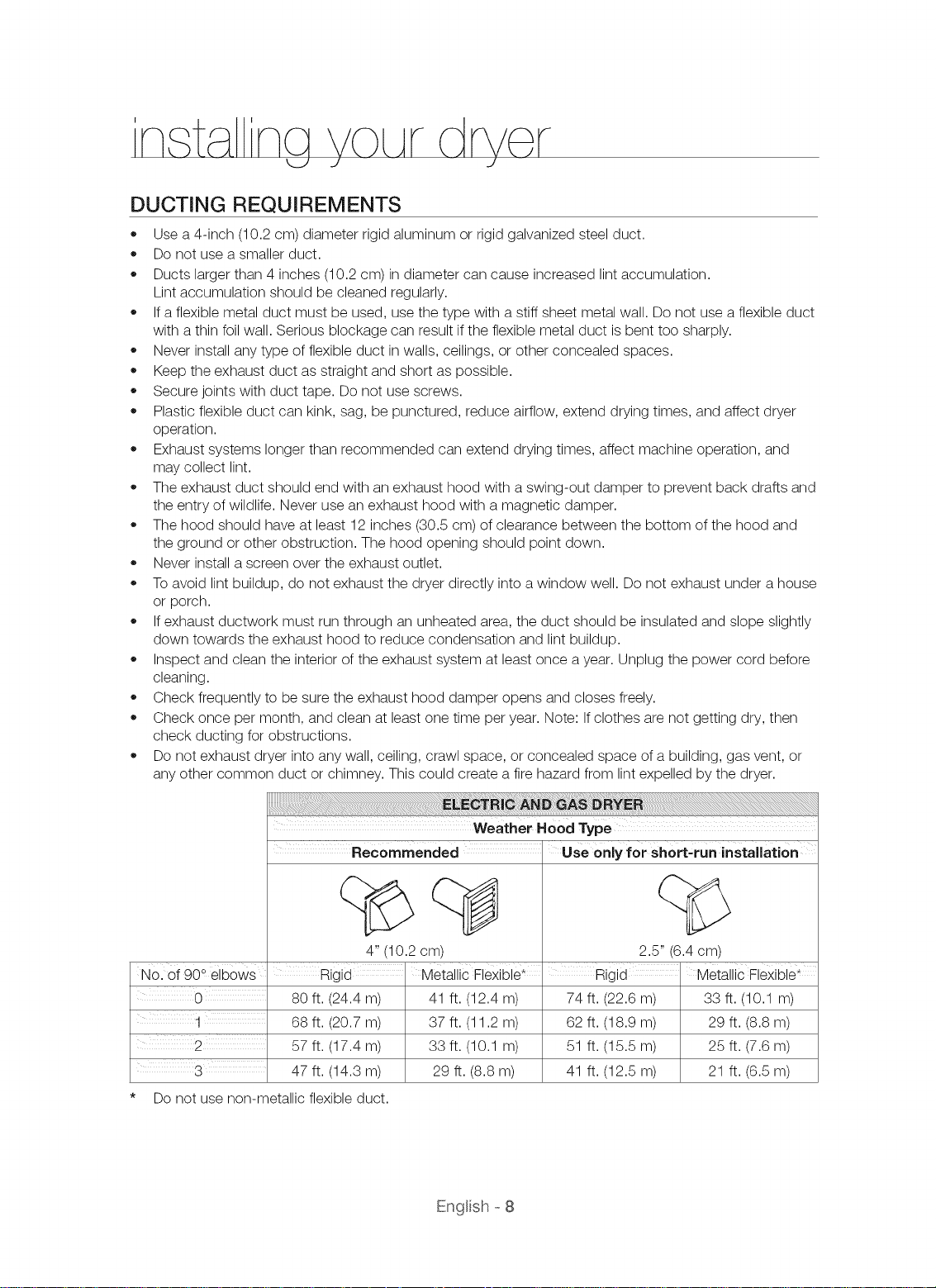
Nol Of900 elboWs
Rigid
80 ft. (24.4 m)
68 ft. (20.7 m)
57 ft. (17.4 m)
3
Do not use non-metallic flexible duct.
47 ft. (14.3 m)
Recommended
4" (10.2 cm)
Metallic Flexible* Rigid Metallic Flexible*
41 ft. (12.4 m) 74 ft. (22.6 m) 33 ft. (10.1 m)
37 ft. (11.2 m) 62 ft. (18.9 m) 29 ft. (8.8 m)
33 ft. (10.1 m) 51 ft. (15.5 m) 25 ft. (7.6 m)
29 ft. (8.8 m) 41 ft. (12.5 m) 21 ft. (6.5 m)
Weather Hood Type
Engl sh - 8
Use only for short,run installation
i
2.5" (6.4 cm)
Ifthe newdryerisbeinginstalledintoanexistingexhaustsystem,you must
makesure:
The exhaust system meets all local, state, and national codes.
That a flexible plastic duct is not used.
To Inspect and clean all lint buildup from inside the existing duct.
The duct is not kinked or crushed.
The exhaust hood damper opens and closes freely.
The static pressure in any exhaust system must not exceed 0.83 inches of water column, or be
less than 0.
This can be measured with the dryer running with a manometer at the point where the exhaust
duct connects to the dryer. A no-heat setting should be used. The dryer tumbler should be
empty and the lint filter clean.
IMPORTANT TO INSTALLER
Please read the following instructions carefully before installing the dryer. These instructions should be kept
for future reference.
Z_ Remove the door from all discarded appliances to avoid the danger of a child suffocating.
WARNING
LOCATION CONSIDERATIONS
Locate the dryer where there is enough space at the front for loading the dryer, and enough space behind
for the exhaust system. This dryer is factory-ready for rear exhaust. To exhaust out the bottom or the right
or the left (electric model only), use the accessory exhaust kit (sold separately). Instructions are included
with the kit. It's important to make sure the room has enough fresh air. The dryer must be located where
there is no air-flow obstruction.
On gas dryers, adequate clearance as noted on the data plate must be maintained to ensure adequate air
for combustion and proper dryer operation.
Do not install or store the dryer in an area where it will be exposed to water and/or weather. Keep the dryer
area clear of combustible materials, gasoline, and other flammable vapors and liquids. A dryer produces
combustible lint. The area around the dryer should be kept lint free.
ALCOVE OR CLOSET INSTALLATION
z_You must exhaust the dryer to the outside to reduce the risk of fire when you install the dryer in alcove
WARN,NGor closet.
No other fuel-burning appliance should be installed in the same closet as the dryer.
WARNING: To reduce the risk of fire, you must exhaust the dryer to the outdoors.
See Exhaust information section.
Minimum clearances between the dryer and adjacent walls or other surfaces are:
2" in front, 17" on top, 1" on either side, and 5" in the back.
The closet front must have two unobstructed air openings for a combined minimum total area of 72 in2
with 3" minimum clearance on the top and bottom. A Iouvered door with equivalent space clearance is
acceptable.
Engl sh - 9
EXHAUSTING
The dryer shall not be exhausted into a chimney, a wall, a ceiling, an attic, a crawl space, or a concealed
space of a building.
Exhausting the dryer to the outside will prevent large amount of lint and moisture from being blown into the
room.
In the United States:
All dryers must be exhausted to the outside.
The required exhaust duct is 4 inches (10.2 cm) in diameter.
Use only those foil-type flexible ducts, if any, specifically identified for use with the appliance
by the manufacturer and that comply with the Outline for Clothes Dryer Transition Duct,
Subject 2158A shall be used.
See "Ducting Requirements" in installing your dryer section for the maximum duct length and
number of bends shall be used.
The total length of flexible metal duct shall not exceed 2.4 m.
Do not assemble the duct with screws or other fastening means that extend into the duct
and catch lint
In
Canada:
®
All dryer must be exhausted to the outside.
®
The exhaust duct should be 4 inches (10.2 cm )in diameter.
®
Use only those foil-type flexible ducts, if any, specifically indentified for use with the appliance
by the manufacturer shall be used.
See "Ducting Requirements" in installing your dryer section for the maximum duct length and
number of bends.
®
The total length of flexible metal duct shall not exceed 2.4 m.
®
Do not assemble the duct with screws or other fastening means that extend into the duct
and catch lint.
Outside the U.S. and Canada:
Refer to the local codes.
A You must exhaust the dryer to the outside to reduce the risk of fire when you install the
....... dryer in an alcove or closet.
NEVER USE A PLASTIC OR NON-METAL FLEXIBLE DUCT.
Ifyour existing ductwork is plastic, non-metal, or combustible, replace it with metal.
Use only a metal exhaust duct that is non-flammable to ensure containment of exhaust air,
heat, and lint.
Engl sh- 10
GAS REQUIREMENTS
Use only natural or LP (liquid propane) gases.
THE INSTALLATION MUST CONFORM WITH LOCAL CODES, OR IN THE ABSENCE OF LOCAL
CODES, WITH THE NATIONAL FUEL GAS CODE ANSVZ223.1, LATEST REVISION (FOR THE UNITED
STATES), OR WITH THE CAN/CGA-B149 INSTALLATION CODES (FOR CANADA).
Gas dryers are equipped with a burner vent for use with natural gas. If you plan to use your dryer with LP
(liquid propane) gas, it must be converted for safe and proper performance by a qualified service technician.
A 1/2" (1.27 era) gas supply line is recommended and must be reduced to connect to the 3/8" (1 cm) gas
line on your dryer. The National Fuel Gas Code requires that an accessible, approved manual gas shut-off
valve be installed within 6" of your dryer.
Gas dryers installed in residential garages must be raised 18 inches (46 cm) above the floor.
Additionally, a 1/8" (0.3 era) N.P.T. (National Pipe Thread) plugged tapping, accessible for test gauge
connection, must be installed immediately upstream of your dryer's gas supply connection.
Your dryer must be disconnected from the gas supply pipe system during any pressure testing of the
system.
DO NOT reuse old flexible metal gas lines. Flexible gas lines must be design certified by the American Gas
Association (CGA in Canada).
* ny pipe joint compound used must be resistant to the action of any liquefied petroleum gas.
As a courtesy, most local gas utilities will Inspect a gas appliance installation.
GAS IGNITION - Your dryer uses an automatic ignition system to ignite the burner.
There is no constant burning pilot.
COMMONWEALTH OF MASSACHUSETTS INSTALLATION
INSTRUCTIONS
Your dryer must be installed by a licensed plumber or gas fitter. A "T" handle manual gas valve must be
installed in the gas supply line to your dryer. If a flexible gas connector is used to install your dryer, the
connector can be no longer than 3' (36").
Z_* Gas leaks may occur in your system, creating a dangerous situation.
....... * Gas leaks may not be detected by smell alone.
Gas suppliers recommend you purchase and install a UL-approved gas detector.
Install and use in accordance with the manufacturer's instructions.
Enql sh - 11
ELECTRICAL REQUIREM ENTS
wiring diagram is located on the plate below the control panel or frame back.
The
Improperly connecting the equipment grounding conductor can result in a risk of electric shock.
WARNING
Check with a qualified electrician or serviceman if you are in doubt as to whether your dryer is
properly grounded. Do not modify the plug provided with your dryer - if it doesn't fit the outlet,
have a proper outlet installed by a qualified electrician.
To prevent unnecessary risk of fire, electrical shock, or personal injury, all wiring and grounding
must be done in accordance with local codes, or in the absence of local codes, with the National
Electrical Code, ANSI/NFPA No. 70-Latest Revision (for the U.S.) or the Canadian Electrical Code
CSA C22.1 - Latest Revisions and local codes and ordinances. It is your responsibility to provide
adequate electrical services for your dryer.
All gas installations must be done in accordance with the national Fuel Code ANSI/Z2231 - Latest
Revision (for the U.S.) or CAN/CGA - B149 Installation Codes - Latest Revision (for Canada) and
local codes and ordinances.
GROUNDING
This dryer must be grounded. In the event of malfunction or breakdown, the ground will reduce the risk of
electrical shock by providing a path of least resistance for the electrical current.
Gas models
WARNING
Your dryer has a cord with an equipment-grounding conductor and a grounding plug.
The plug must be plugged into an appropriate outlet that is properly installed and grounded in
accordance with all local codes and ordinances.
Do not modify the plug provided with your dryer - if it doesn't fit the outlet, have a proper outlet
installed by a qualified electrician.
Never connect the ground wire to plastic plumbing lines, gas lines, or hot water pipes.
Electric models
WARNING
Your dryer has an optional cord with an equipment-grounding conductor and a grounding plug.
This cord is sold separately.
The plug must be plugged into an appropriate outlet that is properly installed and grounded in
accordance with all local codes and ordinances.
Do not modify the plug provided with your dryer - if it doesn't fit the outlet, have a proper outlet
installed by a qualified electrician.
Ifa power cord is not used and the electric dryer is to be permanently wired, the dryer must
be connected to a permanently grounded metal wiring system, or an equipment grounding
conductor must be run with the circuit conductors and connected to the equipment grounding
terminal or lead on the dryer.
Engl sh- 12
ELECTRICAL CONNECTIONS
Before operating or testing, follow all grounding instructions in the grounding section.
An individual branch (or separate) circuit serving only your dryer is recommended. DO NOT USE AN
EXTENSION CORD.
Gas models- U,S, and Canada
A 120 volt, 60 Hz AC approved electrical service, with a 15-ampere fuse or circuit breaker is
required.
Electric models - U,S, only
Most U.S. dryers require a 120 / 240 volt, 60 Hz AC approved electrical service. Some require
120 / 208 volt, 60 Hz approved electrical service. The electric service requirements can be found
on the data label located behind the door. A 30-ampere fuse or circuit breaker on both sides of
the line is required.
If a power cord is used, the cord should be plugged into a 30-ampere receptacle.
The power cord is NOT provided with U.S. electric model dryers.
/k
Risk of Electric Shock
WARNING
When local codes allow, the dryer electrical supply may be connected by means of a new
power supply cord kit, marked for use with a dryer, that is U.L. listed and rated at a minimum of
120/240 volts, 30-ampere with three No. 10 copper wire conductors terminated with closed loop
terminals, open-end spade lugs with turned up ends, or with tinned leads.
Do not reuse a power supply cord from an old dryer. The power cord electric supply wiring
must be supported at the dryer cabinet by a suitable UL-listed strain relief.
,, Grounding through the neutral conductor is prohibited for (1) new branch-circuit installations,
(2) mobile homes, (3) recreational vehicles, and (4) areas where local codes prohibit
grounding through the neutral conductor. (Use a 4-prong plug for a 4 wire receptacle, NEMA
type 14-30R.)
Electric models - Canada Only
A 120 / 240 volt, 60 Hz AC approved electrical service fused through a 30-ampere fuse or
circuit breaker on both sides of the line is required.
All Canadian models are shipped with the power cord attached. The power cord should be
plugged into a 30-ampere receptacle.
permissible
It is not to convert in Canada to 208 volts.
a
dryer
Engl sh- 13
INSTALLATION - GENERAL PROCEDURE
For proper installation, we recommend that you hire a qualified installer.
Read these instructions completely before you begin the installation.
To install the dryer, follow these steps:
1. Move your dryer to an appropriate location for installation. Consider installing the dryer and washer side-
by-side so you have easy access to both appliances.
To move the dryer easily, lay two of the carton cushion-tops on the floor. Tip your dryer on its side so it
lies across both cushion-tops. Push the dryer so that it is near its final location. Set your dryer upright.
Leave enough room around the dryer so you can attach the duct work, power cord, etc.
2.
Ifyou need to change the direction of the door, go to Door Reversal on page 19. When done, return to
Step 3 below.
3.
Review the exhausting section before installing the exhaust system. Install the duct work from your dryer
to the exhaust hood. The crimped end of the duct sections must point away from your dryer. DO NOT
use sheet metal screws when assembling ducting. These joints should be taped. Never use plastic
flexible exhaust material.
A tip for tight installations: Attach a section of the exhaust system to your dryer before putting it in
place. Use duct tape to secure this section to your dryer, but do not cover the ventilation slots at the
back of the dryer cabinet.
4.
Ifyou have an electric model, skip to Step 6. Ifyou have a gas model, go to the next step.
5.
Review the Gas Requirements section, then follow the lettered steps below.
a. Remove the pipe thread protective cap.
b. Apply pipe joint compound or about 1 1/2 wraps of Teflon tape over all threaded connections.
The pipe joint compound must be resistant to the action of liquefied petroleum
any gas.
c. Connect the gas supply to your dryer. An additional fitting is required to connect the 3/4" (1.9 cm)
female thread end of a flexible connector to the 3/8" (1 cm) male threaded end on the dryer.
d. Securely tighten the gas line fitting over the threads.
e. Turn on the gas supply. Check all gas connections for leaks using a soap solution. If bubbles
appear, tighten the connections and recheck. DO NOT use an open flame to check for gas leaks.
f. Go to Step 6 on the next page
Engl sh- 14
6.
Review the Electrical Requirements section, then follow the 3 Wire system connection instructions (Step
7) or 4 Wire system instructions (Step 8) below.
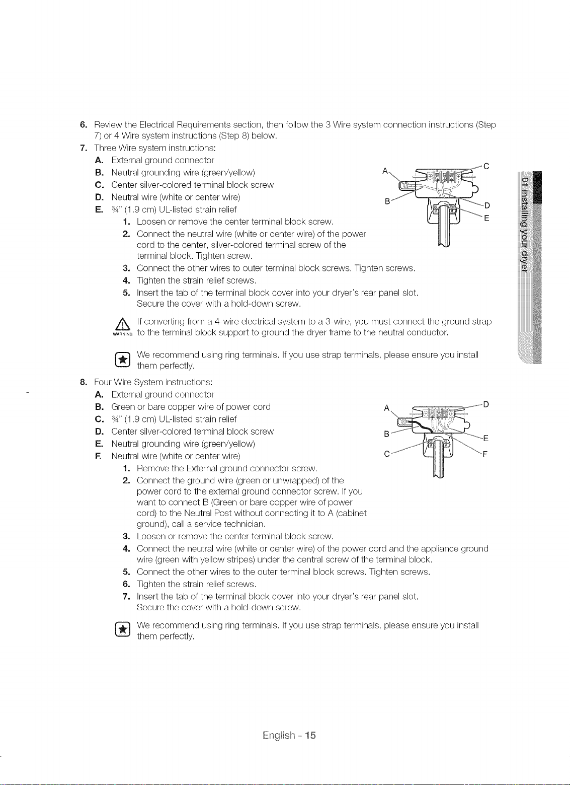
7.
Three Wire system instructions:
A. External ground connector
B. Neutral grounding wire (green/yellow)
O. Center silver-colored terminal block screw
D. Neutral wire (white or center wire)
E. 3_,,(1.9 cm) UL-listed strain relief
1o Loosen or remove the center terminal block screw. E
2. Connect the neutral wire (white or center wire) of the power
cord to the center, silver-colored terminal screw of the
terminal block. Tighten screw.
3. Connect the other wires to outer terminal block screws. Tighten screws.
4. Tighten the strain relief screws.
5. Insert the tab of the terminal block cover into your dryer's rear panel slot.
Secure the cover with a hold-down screw.
Ifconverting from a 4-wire electrical system to a 3-wire, you must connect the ground strap
WARNING
to the terminal block support to ground the dryer frame to the neutral conductor.
[_ e recommend using ring terminals. Ifyou use strap terminals, please ensure you install
them perfectly.
8.
Four
Wire System instructions:
A,
External ground connector
B.
Green or bare copper wire of power cord
O.
3_,,(1.9 cm) UL-listed strain relief
D.
Center silver-colored terminal block screw
E.
Neutral grounding wire (green/yellow)
F.
Neutral wire (white or center wire)
1. Remove the External ground connector screw.
2. Connect the ground wire (green or unwrapped) of the
power cord to the external ground connector screw. Ifyou
want to connect B (Green or bare copper wire of power
cord) to the Neutral Post without connecting it to A (cabinet
ground), call a service technician.
3. Loosen or remove the center terminal block screw.
4. Connect the neutral wire (white or center wire) of the power cord and the appliance ground
wire (green with yellow stripes) under the central screw of the terminal block.
5. Connect the other wires to the outer terminal block screws. Tighten screws.
6. Tighten the strain relief screws.
7. Insert the tab of the terminal block cover into your dryer's rear panel slot.
Secure the cover with a hold-down screw.
We recommend using ring terminals. If you use strap terminals, please ensure you install
them perfectly.
Engl sh- 15
U.S. MODELS:
Z_ Risk Of Electric Shock
WARNING
All U.S.models are designed for a 3-WIRE SYSTEM CONNECTION. The dryer frame is grounded to
the neutral conductor at the terminal block. A 4-WIRE SYSTEM CONNECTION is required for new or
remodeled construction, mobile homes, or if local codes do not permit grounding through neutral. If
you use the 4-wire system, you cannot ground the dryer frame to the neutral conductor at the terminal
block.
Remove the terminal block cover plate. Insert the power cord with a UL-listed strain relief through the
hole provided in the cabinet near the terminal block.
A strain relief must be used. Do not loosen the nuts already installed on the terminal block. Be sure
they are tight. Use a 3/8" (lcm) deep well socket.
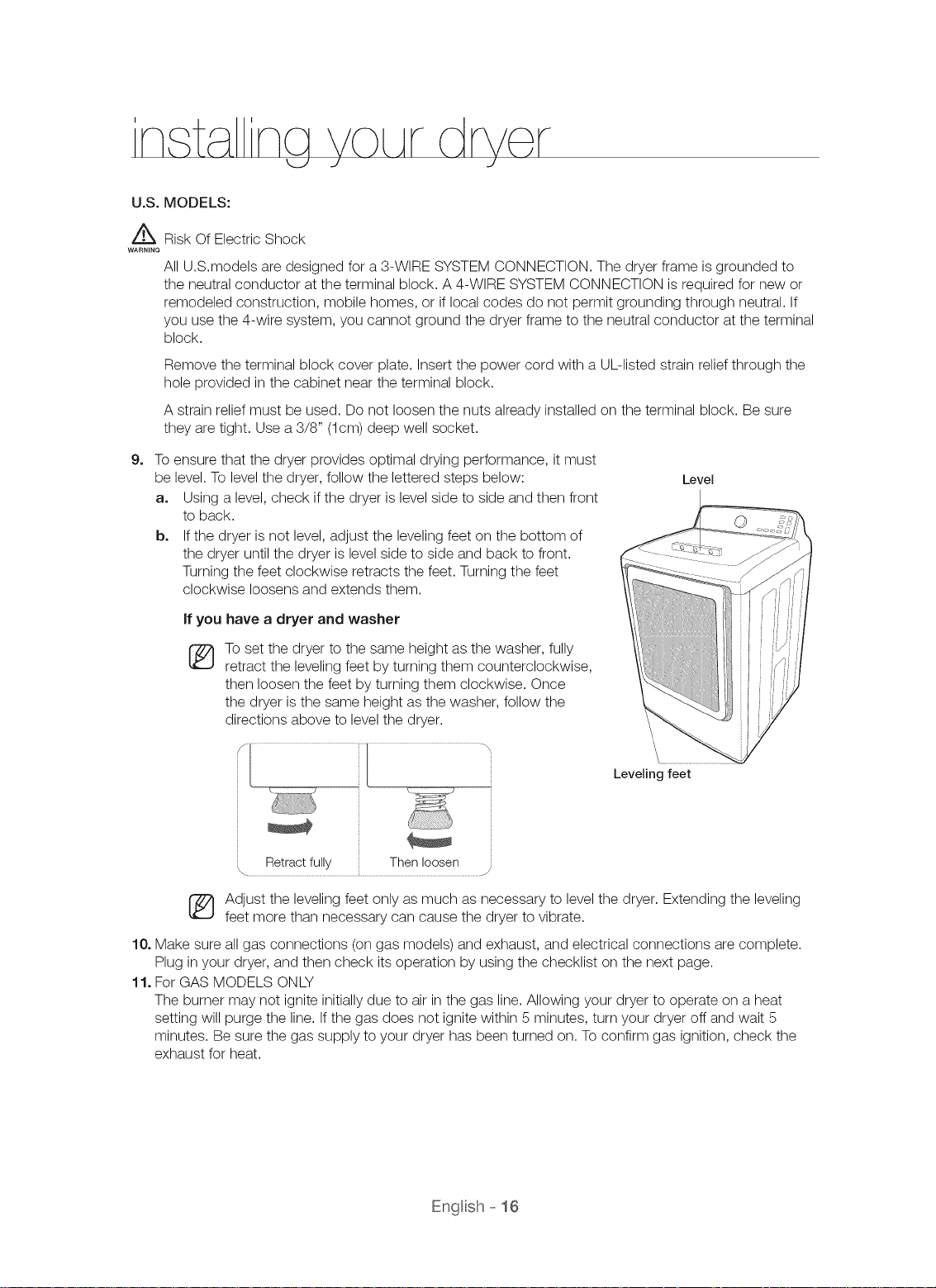
9_
To ensure that the dryer provides optimal drying performance, it must
be level. To level the dryer, follow the lettered steps below:
Level
a. Using a level, check if the dryer is level side to side and then front
to back.
b. If the dryer is not level, adjust the leveling feet on the bottom of
the dryer until the dryer is level side to side and back to front.
Turning the feet clockwise retracts the feet. Turning the feet
clockwise loosens and extends them.
if you have a dryer and washer
To set the dryer to the same height as the washer, fully
®
retract the leveling feet by turning them counterclockwise,
then loosen the feet by turning them clockwise. Once
the dryer is the same height as the washer, follow the
directions above to level the dryer.
Leveling feet
Adjust the leveling feet only as much as necessary to level the dryer. Extending the leveling
feet more than necessary can cause the dryer to vibrate.
10. Make sure all gas connections (on gas models) and exhaust, and electrical connections are complete.
Plug in your dryer, and then check its operation by using the checklist on the next page.
11. For GAS MODELS ONLY
The burner may not ignite initially due to air in the gas line. Allowing your dryer to operate on a heat
setting will purge the line. If the gas does not ignite within 5 minutes, turn your dryer off and wait 5
minutes. Be sure the gas supply to your dryer has been turned on. To confirm gas ignition, check the
exhaust for heat.
Engl sh- 16
CONNECTING THE INLET HOSE
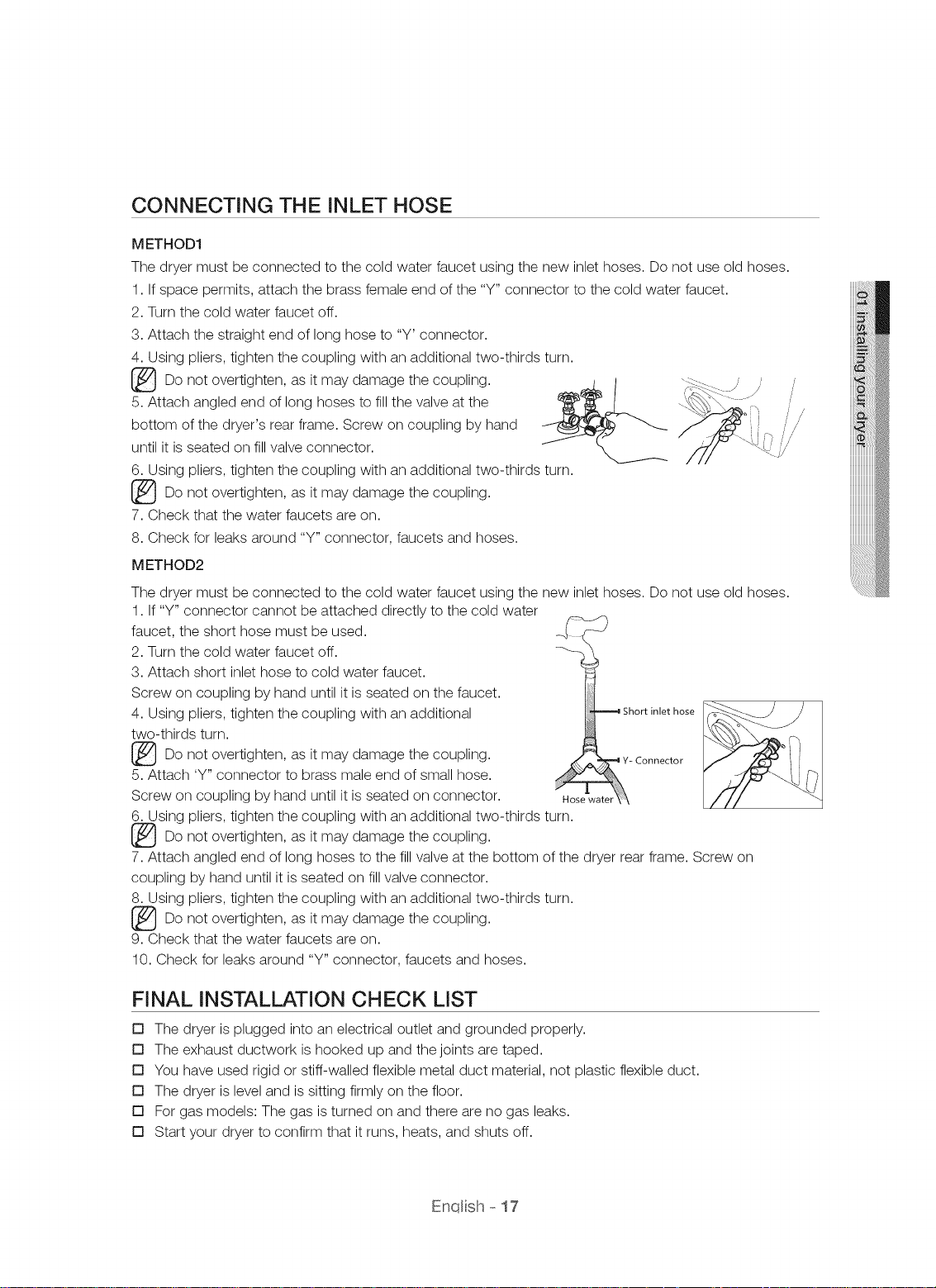
METHOD1
The dryer must be connected to the cold water faucet using the new inlet hoses. Do not use old hoses.
1. Ifspace permits, attach the brass female end of the "Y" connector to the cold water faucet.
2. Turn the cold water faucet off.
3. Attach the straight end of long hose to "Y' connector.
4. Using pliers, tighten the coupling with an additional two-thirds turn.
Do not overtighten, as it may damage the coupling. ,_L, l
5. Attach angled end of long hoses to fill the valve at the
bottom of the dryer's rear frame. Screw on coupling by hand
until it is seated on fill valve connector.
6. Using pliers, tighten the coupling with an additional two-thirds turn.
Do not overtighten, as it may damage the coupling.
7. Check that the water faucets are on.
8. Check for leaks around "Y" connector, faucets and hoses.
METHOD2
The dryer must be connected to the cold water faucet using the new inlet hoses. Do not use old hoses.
1. If"Y" connector cannot be attached directly to the cold water
faucet, the short hose must be used. _,( _-_/
2. Turn the cold water faucet off.
3. Attach short inlet hose to cold water faucet.
Screw on coupling by hand until it is seated on the faucet.
4. Using pliers, tighten the coupling with an additional Shortinlethose
two-thirds turn.
Do not overtighten, as it may damage the coupling. -Connector
5. Attach 'Y" connector to brass male end of small hose. ,,
Screw on coupling by hand until it is seated on connector. Hosewater\ \
6. Using pliers, tighten the coupling with an additional two-thirds turn.
Do not overtighten, as it may damage the coupling.
7. Attach angled end of long hoses to the fill valve at the bottom of the dryer rear frame. Screw on
coupling by hand until it is seated on fill valve connector.
8. Using pliers, tighten the coupling with an additional two-thirds turn.
[_Do not overtighten, as may damage coupling.
9. Check that the water faucets are on.
10. Check for leaks around "Y" connector, faucets and hoses.
it the
FINAL INSTALLATION CHECK LIST
[] The dryer is plugged into an electrical outlet and grounded properly.
[] The exhaust ductwork is hooked up and the joints are taped.
[] You have used rigid or stiff-walled flexible metal duct material, not plastic flexible duct.
[] The dryer is level and is sitting firmly on the floor.
[] For gas models: The gas is turned on and there are no gas leaks.
[] Start your dryer to confirm that it runs, heats, and shuts off.
Enql sh - 17
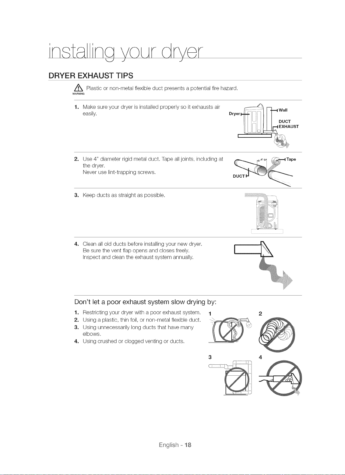
DRYER EXHAUST TIPS
Z_ Plastic or non-metal flexible duct presents a potential fire hazard.
WARNING
1. Make sure your dryer is installed properly so it exhausts air
easily.
2. Use 4" diameter rigid metal duct. Tape all joints, including at
the dryer.
Never use lint-trapping screws.
3. Keep ducts as straight as possible.
4.
Clean all old ducts before installing your new dryer.
Be sure the vent flap opens and closes freely.
Inspect and clean the exhaust system annually.
[
Don't let a poor exhaust system slow drying by:
1. Restricting your dryer with a poor exhaust system. 1
2. Using a plastic, thin foil, or non-metal flexible duct.
3. Using unnecessarily long ducts that have many
elbows.
4. Using crushed or clogged venting or ducts.
3 4
Engl sh- 18
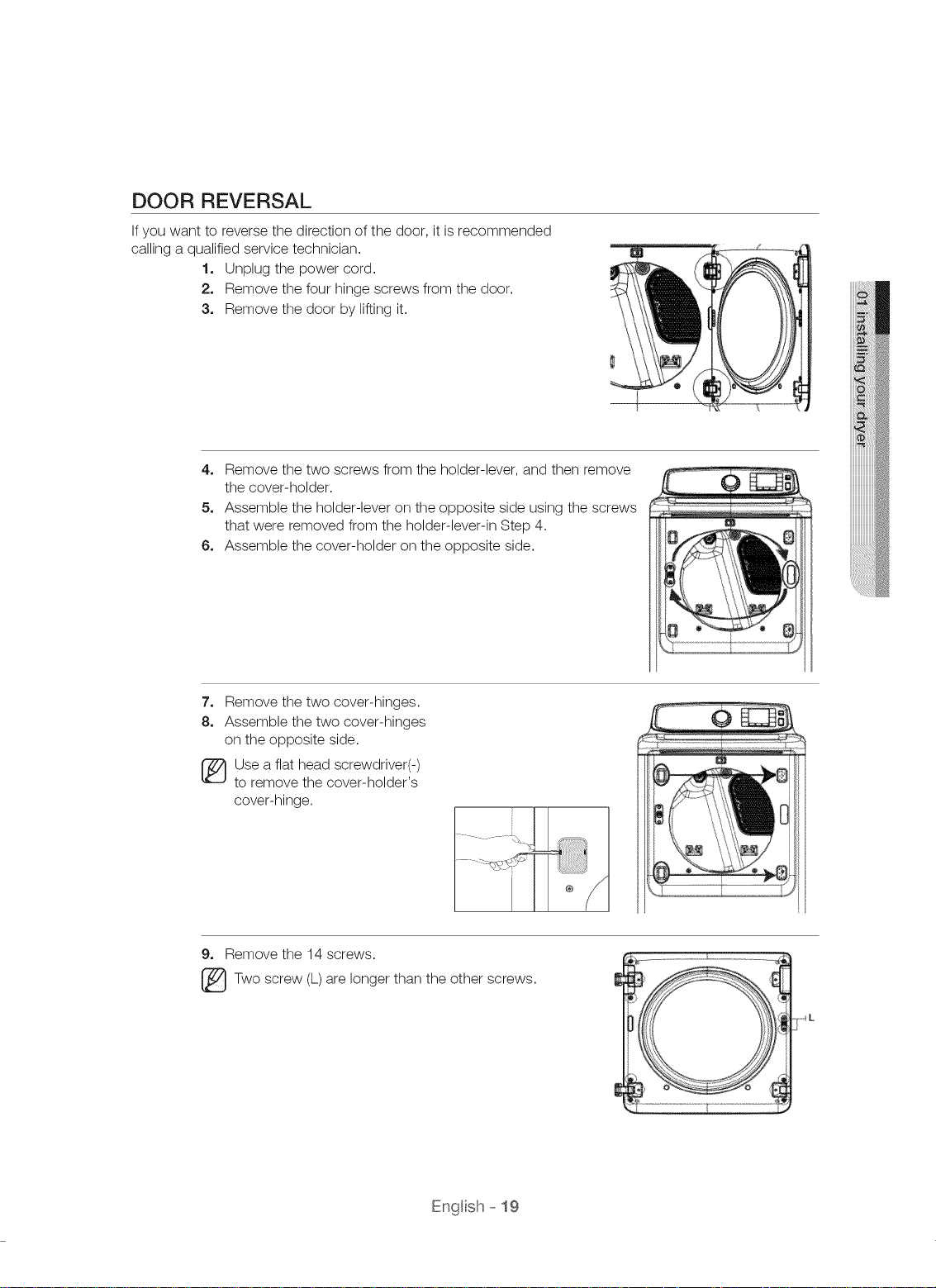
DOOR REVERSAL
Ifyou want to reverse the direction of the door, it is recommended
calling a qualified service technician.
1o Unplug the power cord.
2. Remove the four hinge screws from the door.
3o Remove the door by lifting it.
4. Remove the two screws from the holder-lever, and then remove
the cover-holder.
5o Assemble the holder-lever on the opposite side using the screws
that were removed from the holder-lever-in Step 4.
6, Assemble the cover-holder on the opposite side.
7. Remove the two cover-hinges.
8. Assemble the two cover-hinges
on the opposite side.
Use a flat head screwdriver(-)
to remove the cover-holder's
cover-hinge.
9, Remove the 14 screws.
Two screw (L) are longer than the other screws.
/
Engl sh- 19
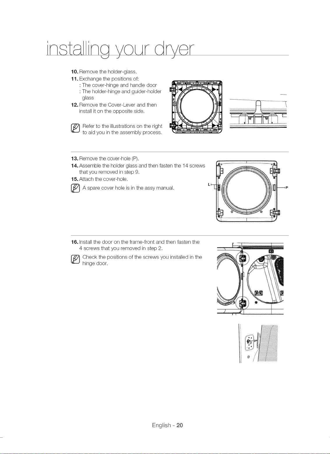
10, Remove the holder-glass.
11, Exchange the positions of:
: The cover-hinge and handle door
: The holder-hinge and guider-holder
glass
12, Remove the Cover-Lever and then
install it on the opposite side.
_ efer to the illustrations on the right
to aid you in the assembly process.
13, Remove the cover-hole (P).
14, Assemble the holder glass and then fasten the 14 screws
that you removed in step 9.
15, Attach the cover-hole.
cover
spare
_A hole is in the manual.
assy
16, Install the door on the frame-front and then fasten the
4 screws that you removed in step 2.
_ heck the positions of the screws you installed in the
hinge door.
Engl sh- 20
nq nstrLActons, t
I _ J I
z_To reduce the risk of fire, electric shock, or injury to read the IMPORTANT SAFETY
....... INSTRUCTIONS before operating this appliance.
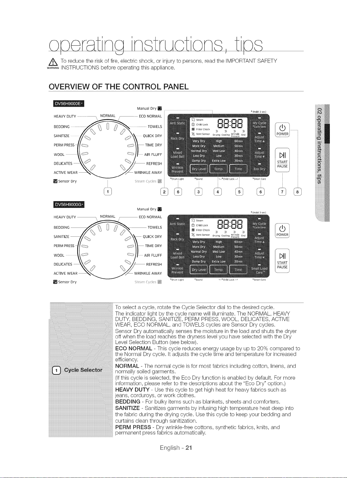
OVERVIEW OF THE CONTROL PANEL
persons,
Manual Dry [] ]
Manual Dry []
HEAVY DUTY _ ECO NORMAL
.EDD,N0 TOWELS
SANITIZE //:_-_. _'_" _" ,_,/_)'_k QUICK DRY
.ERMPRESSl[_X ,_i}y T,MEDRY
WOOLk}. 7' A,RFLOFF
DEUCATES _,_ __ REFRESH
ACTIVE WEAR ___ WRINKLE AWAY
[] Sensor Dry , : _}
*Drum light *Sound L'Child Lock _ *Smart Care
*(Hold 3 sac)
*(Hold 3 sac)
iiiiiiiQ i
To select a cycle, rotate the Cycle Selector dial to the desired cycle.
The indicator light by the cycle name will illuminate. The NORMAL, HEAVY
DUTY, BEDDING, SANITIZE, PERM PRESS, WOOL, DELICATES, ACTIVE
WEAR, ECO NORMAL, and TOWELS cycles are Sensor Dry cycles.
Sensor Dry automatically senses the moisture in the load and shuts the dryer
off when the load reaches the dryness level you have selected with the Dry
Level Selection Button (see below).
ECO NORMAL - This cycle reduces energy usage by up to 20% compared to
the Normal Dry cycle. It adjusts the cycle time and temperature for increased
efficiency.
NORMAL - The normal cycle is for most fabrics including cotton, linens, and
normally soiled garments.
(If this cycle is selected, the Eco Dry function is enabled by default. For more
information, please refer to the descriptions about the "Eco Dry" option.)
HEAVY DUTY- Use this cycle to get high heat for heavy fabrics such as
jeans, corduroys, or work clothes.
BEDDING - For bulky items such as blankets, sheets and comforters.
SANITIZE - Sanitizes garments by infusing high temperature heat deep into
the fabric during the drying cycle. Use this cycle to keep your bedding and
curtains clean through sanitization.
PERM PRESS - Dry wrinkle-free cottons, synthetic fabrics, knits, and
permanent press fabrics automatically.
EngBh- 21
WOOL - For machine washable and tumble dryable wool only.
DEMCATES - The DELICATES cycle is designed to dry heat-sensitive items at
a low drying temperature.
ACTIVE WEAR - The ACTIVE WEAR cycle is for exercise wear and outdoor
wear such as sports jerseys, training pants, water-repellent jackets and other
performance clothing. Thick fabrics like a zipper or velcro closure of a jacket,
or training socks may not be completely dried.
TOWELS - To dry bath towels and similar items.
QUICK DRY - Provides a 30 minute drying cycle.
TIME DRY - The TIME DRY cycle allows you to select a cycle time in minutes.
(If this cycle is selected, the Eco Dry function is enabled by default. For more
information, please refer to the descriptions about the "Eco Dry" option.)
AIR FLUFF - The AIR FLUFF cycle tumbles the load in room temperature air.
REFRESH - This cycle is best for smoothing out wrinkles and reducing odors
from loads consisting of one to four dry items. In this cycle a small amount
of water is sprayed into the dryer drum after several minutes of tumbling with
heat.
WRINKLE AWAY - The WRINKLE AWAY cycle removes wrinkles from clothes
stored in closets, etc. It provides wrinkle release via optimized steam care. You
can change the drying time. (Minimum time : 20 minutes)
* For best results, load no more than 3 items.
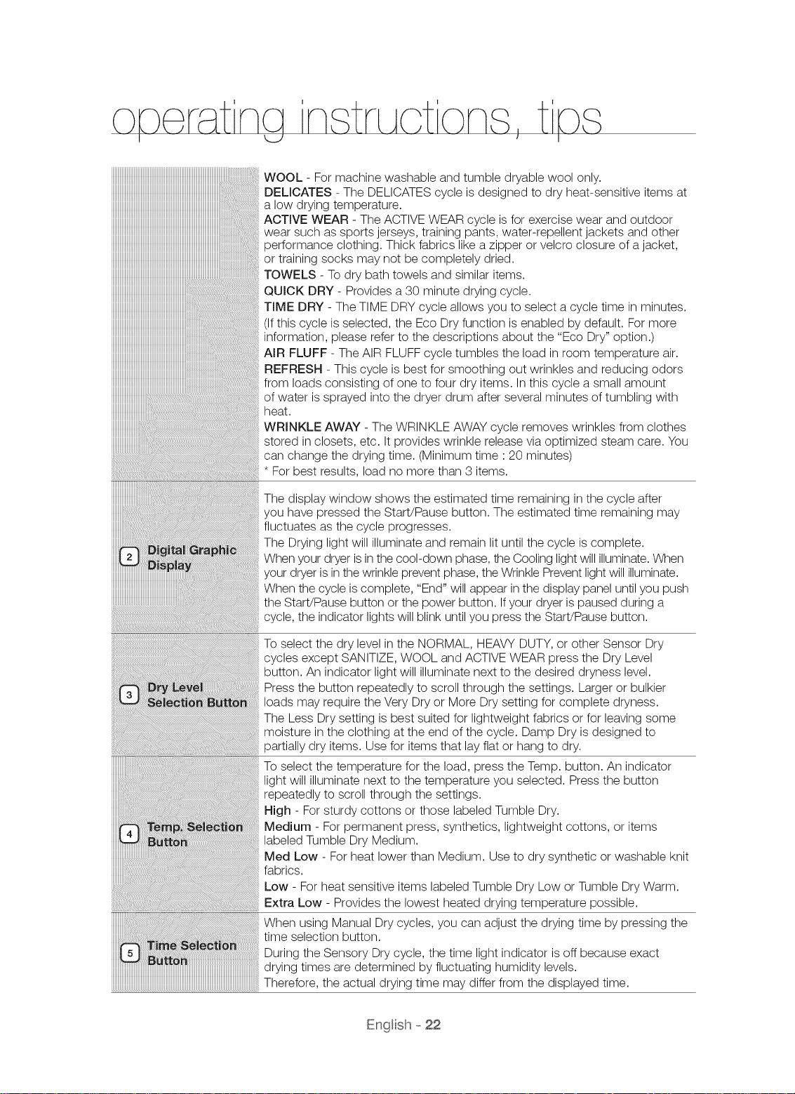
The display window shows the estimated time remaining in the cycle after
you have pressed the Start/Pause button. The estimated time remaining may
fluctuates as the cycle progresses.
The Drying light will illuminate and remain lit until the cycle is complete.
When your dryer is in the cool-down phase, the Cooling light will illuminate. When
your dryer is in the wrinkle prevent phase, the Wrinkle Prevent light will illuminate.
When the cycle is complete, "End" will appear in the display panel until you push
the Start!Pause button or the power button. Ifyour dryer is paused during a
cycle, the indicator lights will blink until you press the Start/Pause button.
To select the dry level in the NORMAL, HEAVY DUTY, or other Sensor Dry
cycles except SANITIZE, WOOL and ACTIVE WEAR press the Dry Level
button. An indicator light will illuminate next to the desired dryness level.
Press the button repeatedly to scroll through the settings. Larger or bulkier
loads may require the Very Dry or More Dry setting for complete dryness.
The Less Dry setting is best suited for lightweight fabrics or for leaving some
moisture in the clothing at the end of the cycle. Damp Dry is designed to
partially dry items. Use for items that lay flat or hang to dry.
To select the temperature for the load, press the Temp. button. An indicator
light will illuminate next to the temperature you selected. Press the button
repeatedly to scroll through the settings.
High - For sturdy cottons or those labeled Tumble Dry.
Medium - For permanent press, synthetics, lightweight cottons, or items
labeled Tumble Dry Medium.
Med Low - For heat lower than Medium. Use to dry synthetic or washable knit
fabrics.
Low - For heat sensitive items labeled Tumble Dry Low or Tumble Dry Warm.
Extra Low - Provides the lowest heated drying temperature possible.
When using Manual Dry cycles, you can adjust the drying time by pressing the
time selection button.
During the Sensory Dry cycle, the time light indicator is off because exact
drying times are determined by fluctuating humidity levels.
Therefore, the actual drying time may differ from the displayed time.
Engl sh- 22
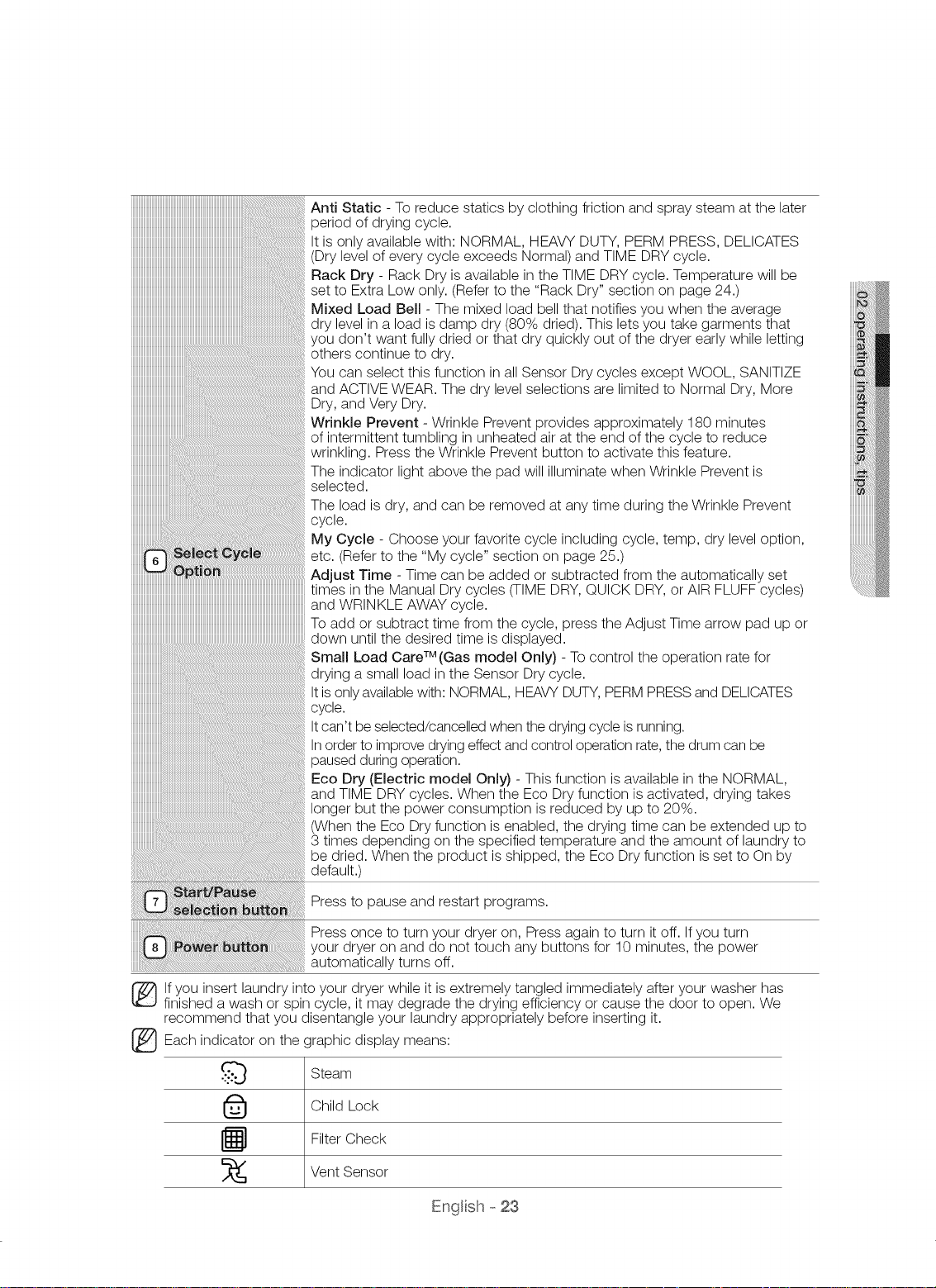
Anti Static - To reduce statics by clothing friction and spray steam at the later
period of drying cycle.
It is only available with: NORMAL, HEAVY DUTY, PERM PRESS, DELICATES
(Dry level of every cycle exceeds Normal) and TIME DRY cycle.
Rack Dry - Rack Dry is available in the TIME DRY cycle. Temperature will be
set to Extra Low only. (Refer to the "Rack Dry" section on page 24.)
Mixed Load Bell - The mixed load bell that notifies you when the average
dry level in a load is damp dry (80% dried). This lets you take garments that
you don't want fully dried or that dry quickly out of the dryer early while letting
others continue to dry.
You can select this function in all Sensor Dry cycles except WOOL, SANITIZE
and ACTIVE WEAR. The dry level selections are limited to Normal Dry, More
Dry, and Very Dry.
Wrinkle Prevent - Wrinkle Prevent provides approximately 180 minutes
of intermittent tumbling in unheated air at the end of the cycle to reduce
wrinkling. Press the Wrinkle Prevent button to activate this feature.
The indicator light above the pad will illuminate when Wrinkle Prevent is
selected.
The load is dry, and can be removed at any time during the Wrinkle Prevent
cycle.
My Cycle - Choose your favorite cycle including cycle, temp, dry level option,
etc. (Refer to the "My cycle" section on page 25.)
iiiiiiiiiiiiiiiiiiiiiiiiiiiiiiiiiiiiiiiiiiiiiiiiiiiiiiiiiiiiiiiiiiiiiiiiiiiiiiiiiiiiiiiiiiiiiiiiiiiiiiiiiiiiiiiiiiiiiiiiiiiiiiiiiiiiiiiiiiiiiii
iiiiiiiiiiiiiiiiiiiiiiiiiiiiiiiiiiiiiiiiiiiiiiiiiiiiiiiiiiiiiiiiiiiiiiiiiiiiiiiiiiiiiiiiiiiiiiiiiiiiiiiiiiiiiiiiiiiiiiiiiiiiiiiiiiiiiiiiiiiiiii
iiiiiiiiiiiiiiiiiiiiiiiiiiiiiiiiiiiiiiiiiiiiiiiiiiiiiiiiiiiiiiiiiiiiiiiiiiiiiiiiiiiiiiiiiiiiiiiiiiiiiiiiiiiiiiiiiiiiiiiiiiiiiiiiiiiiiiiiiiiiiii
iiiiiiiiiiiiiiiiiiiiiiiiiiiiiiiiiiiiiiiiiiiiiiiiiiiiiiiiiiiiiiiiiiiiiiiiiiiiiiiiiiiiiiiiiiiiiiiiiiiiiiiiiiiiiiiiiiiiiiiiiiiiiiiiiiiiiiiiiiiiiii
iiiiiiiiiiiiiiiiiiiiiiiiiiiiiiiiiiiiiiiiiiiiiiiiiiiiiiiiiiiiiiiiiiiiiiiiiiiiiiiiiiiiiiiiiiiiiiiiiiiiiiiiiiiiiiiiiiiiiiiiiiiiiiiiiiiiiiiiiiiiiii
Adjust Time - Time can be added or subtracted from the automatically set
times in the Manual Dry cycles (TIME DRY, QUICK DRY, or AIR FLUFF cycles)
and WRINKLE AWAY cycle.
To add or subtract time from the cycle, press the Adjust Time arrow pad up or
down until the desired time is displayed.
Small Load Care TM (Gas model Only) - To control the operation rate for
drying a small load in the Sensor Dry cycle.
It isonly availablewith: NORMAL, HEAVY DUTY,PERM PRESSand DELICATES
cycle.
Itcan't be selected/cancelled when the drying cycle isrunning.
In order to improve drying effect and control operation rate, the drum can be
paused during operation.
Eco Dry (Electric model Only) - This function is available in the NORMAL,
and TIME DRY cycles. When the Eco Dry function is activated, drying takes
longer but the power consumption is reduced by up to 20%.
(When the Eco Dry function is enabled, the drying time can be extended up to
3 times depending on the specified temperature and the amount of laundry to
be dried. When the product is shipped, the Eco Dry function is set to On by
default.)
Press to pause and restart programs.
Press once to turn your dryer on, Press again to turn it off. If you turn
your dryer on and do not touch any buttons for 10 minutes, the power
automatically turns off.
lf you insert laundry into your dryer while it is extremely tangled immediately after your washer has
finished a wash or spin cycle, it may degrade the drying efficiency or cause the door to open. We
recommend that you disentangle your laundry appropriately before inserting it.
Each indicator on the graphic display means:
Steam
Child Lock
Filter Check
Vent Sensor
Engl sh- 23
na nstnActons, t
I _ J I
RACK DRY
Using the drying rack
1. The drying rack is installed in the drum at in default state.
2. When using this dryer for the first time, remove the drying rack from the drum. Pull upwards
vertically and take the drying rack out of the drum. Remove the package and keep it properly
stored.
3. When you need to use drying rack, refer to the following steps for installation.
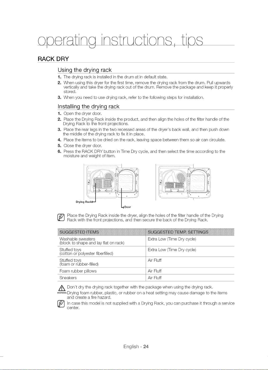
Installing the drying rack
1. Open the dryer door.
2. Place the Drying Rack inside the product, and then align the holes of the filter handle of the
Drying Rack to the front projections.
3. Place the rear legs in the two recessed areas of the dryer's back wall, and then push down
the middle of the drying rack to fix it in place.
4. Place the items to be dried on the rack, leaving space between them so air can circulate.
5. Close the dryer door.
6. Press the RACK DRY button in Time Dry cycle, and then select the time according to the
moisture and weight of item.
Drying Rackl ,=a
='1Door
_ lace the Drying Rack inside the dryer, align the holes of the filter handle of the Drying
Rack with the front projections, and then secure the back of the Drying Rack.
Washable sweaters Extra Low (Time Dry cycle)
(block to shape and lay flat on rack)
Stuffed toys Extra Low (Time Dry cycle)
(cotton or polyester fiberfilled)
Stuffed toys Air Fluff
(foam or rubber-filled)
Foam rubber pillows Air Fluff
Sneakers Air Fluff
A Don't dry the drying rack together with the package when using the drying rack.
....... Drying foam rubber, plastic, or rubber on a heat setting may cause damage to the items
and create a fire hazard.
_ln case this model is not supplied with a Drying Rack, can purchase it through a service
center.
............................................................................./...........
you
Engl sh- 24
 Loading...