

Samsung DV456EWHDWR/AA, DV400GWHDWR/AA, DV456GWHDSU/AA, DV456EWHDSU/AA, DV456 Series Technical Information
...Page 1
1
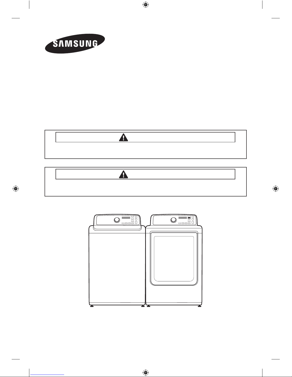
CLOTHES DRYER
Technical Information
CAUTION
All safety information must be follwed as provided in Service Manual of
DV456*,DV422*,DV400*
.
WARNING
To avoid risk of electrical shock, personal injury or death; disconnect power to dryer
before servicing, unless testing requires power.
Code No. : DC68-03171A_EN
• Due to possibility of personal injury or property damage, always contact an authorized
technician for servicing or repair of this unit.
• Refer to Service Manual (DV456*,DV422*,DV400*) for detailed installation, operating, testing,
troubleshooting, and disassembly instructions.
[HUDSON]_Technical_information-03171A_EN.indd 1 2012-02-03 �� 5:01:21
Page 2

2
ERROR ITEMS AND DIAGNOSTIC CODES
An occurrence of an Error will make a sound of error melody for 5sec and continuously show one
of the Error Displays from the following errors.
Error Display Trigger Action Taken
tE
The Thermistor resistance is
very low or high.
Check for:
- Clogged lint screen.
- Restricted vent system.
- Check Thermistor resistance.
HE
Invalid heating Temp in running
the dryer
Check for:
- Restricted vent system.
- Check Thermistor resistance.
dE
Running the dryer with door
open
Check for:
- Close the door, and run the dryer
- Loose or open wire terminals in Door
Sense circuit.
dF
Invalid door state for more than
256 milliseconds
Check for:
- Loose or open wire terminals in Door
Sense circuit.
bE
(DV422, DV400)
bE2
Invalid state of key circuit short
for 30 secs
Check for:
- Display PCB key circuit short or not
FE Invalid power source Frequency
Check for:
- Not using regular power source frequency
- Invalid power frequency sense circuit
AE
Electronic Control Problem
(Communication Error)
Check for:
- Check PCB and Wire harness.
- Replace PCB.
Et
Invalid state of EEPROM
communication
Check for :
- PCB with Eeprom circuit.
2E
The machine has temporarily
stopped and all buttons except
for the power button do not
work.
If the problem continues even after
applying the normal voltage, replace the
PCB.
ALIGNMENT AND ADJUSTMENTS
WARNING
To avoid risk of electrical shock, personal injury or death; disconnect power to dryer before
servicing, unless testing requires power.
[HUDSON]_Technical_information-03171A_EN.indd 2 2012-02-03 �� 5:01:21
Page 3
3
TEST MODE
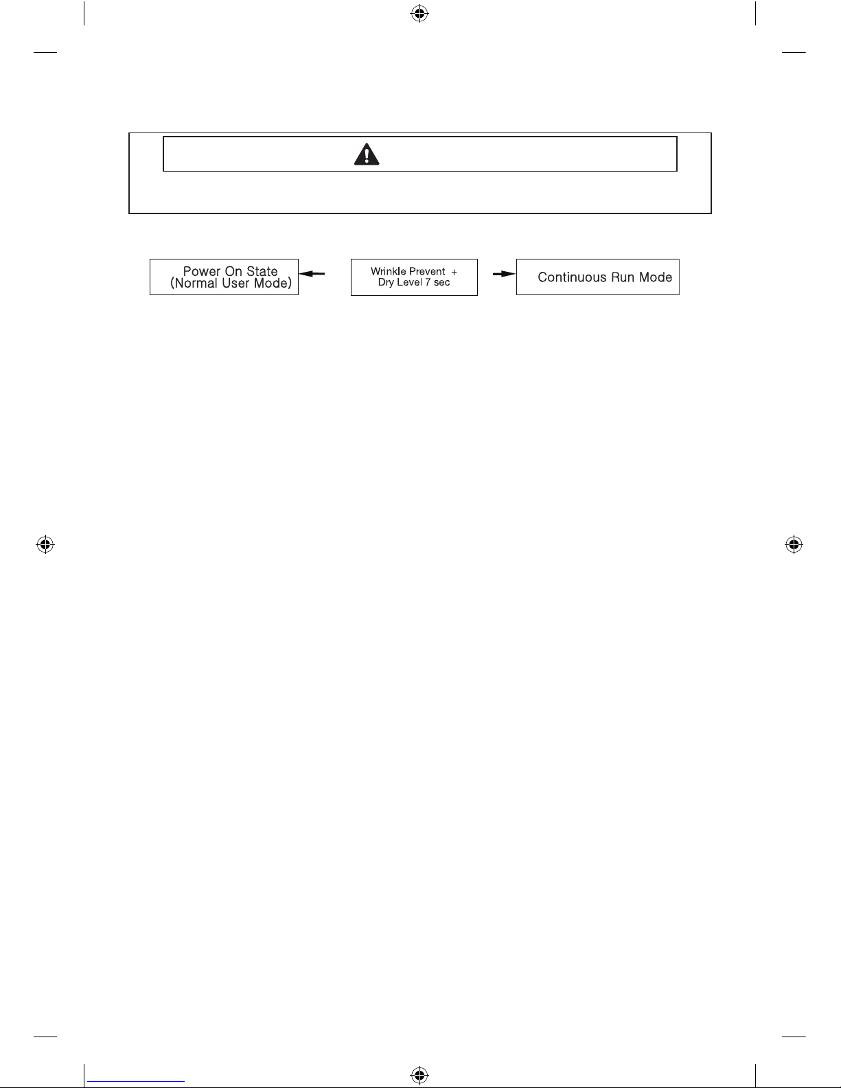
Continuous Run Mode:
1. Press Wrinkle Prevent + Dry Level for 7 sec during Power On State (Normal User Mode) .
2. Once in Continuous Run Mode, display “CC” for 1 sec and the number of Cycle for 1 sec and
the remaining time for 1 sec in turns.
3. The previous cycle will restart during Continuous Run Mode until the mode is deactivated.
4. During Continuous Run Mode, press Wrinkle Prevent + Dry Level for 7 seconds to return to
normal user mode.
Service Mode
Denition of Service Mode
- Dryer must be on before Service Mode can be entered.
- Upon entry into Service Mode, the Sensor Bar Touch Data will be shown (Default Service
Mode).
How to Enter:
- To enter Service Mode, press Wrinkle Prevent and Temp Keys for 3 seconds, until it sends out a
beeping sound.
- If pressing Wrinkle Prevent + Temp Keys for 3 seconds in Service mode , it will return Normal
mode.
- Even though entering Service mode, the operating cycle will not be inuenced.
Sensor Bar Touch Data Mode
Denition of Sensor Bar Touch Data Mode:
- This action will put the dryer into sensor bar touch data mode
- Dryer will display Sensor Bar data. This mode is default mode of entering service mode
How to Enter:
- With Power On pressing Wrinkle Prevent and Temp Keys for 3 seconds
Cycle Count Mode
Denition of Cycle Count Mode:
- This mode is to bring up the total number of cycles that User have carried out.
How to Enter:
- To enter cycle count mode press the Wrinkle Prevent in Service Mode.
Software Version Mode
Denition of Software Version Mode:
- It is to retrieve its software version
How to Enter:
- At Service Mode, press Temp until it sends out a beeping sound
ex) In case of “U0 05”, U0 means major version “U0” 05 means minor version “05”
- If press Temp key In Software Version Mode, it will return Service Mode.
ALIGNMENT AND ADJUSTMENTS
WARNING
To avoid risk of electrical shock, personal injury or death; disconnect power to dryer before
servicing, unless testing requires power.
[HUDSON]_Technical_information-03171A_EN.indd 3 2012-02-03 �� 5:01:21
Page 4

4
Data Display Mode
Denition of Temperature Display Mode:
- Display Mode 0 : Temperature data(Celsius)
- Display Mode 1 : Average Touch Sensor data for 1 minute
- Display Mode 2 : Average Temperature(Celsius) data for 1minute
How to Enter:
- With Power On, press AdjustUp Key + AdjsutDown Key for 7 seconds until it sends out a
beeping sound .
- If not pressed any keys for 5 minutes, it will be set back from Data Display Mode
- If pressing AdjustUp Key in this mode ,Display Mode ID will be increased.
- If pressing AdjustDown Key in this mode ,Display Mode ID will be decreased.
• Converting °C
°F
Celsius(°C) -30 -10 10 30 50 70
F =9/5C + 32
Fahrenheit(°F) -22 14 50 86 122 158
System Check Mode
Denition of System Check Mode:
- “ t2 ” will display.
- System Check Mode(t2 mode) Progress Function Performed Start/Pause
Motor(CW) Relay On Heater Relay On Heater Relay O, Motor(CW) Relay O
How to Enter:
- While in Power O, pressing the Dry Level + Power keys simultaneously will put the dryer into
the System Check mode
ALIGNMENT AND ADJUSTMENTS
WARNING
To avoid risk of electrical shock, personal injury or death; disconnect power to dryer before
servicing, unless testing requires power.
[HUDSON]_Technical_information-03171A_EN.indd 4 2012-02-03 �� 5:01:21
Page 5
5
TROUBLE DIAGNOSIS
- As the micom dry machine is congured of the complicate structure, there might be the
service call.
Below information is prepared for exact trouble diagnosis and suitable repair guide.
Caution for the Repair and Replacement
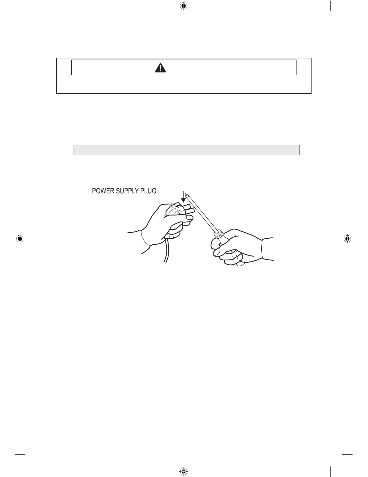
1) As some electronic components are damaged by the charged static electricity from the resin
part of dryer or the human body, prepare the human body earth or remove the potential
dier ence of the human body and dryer by contacting the power supply plug when the work
contacting to PCB is executed.
2) As the P.C.B assembly is designed for no trouble, do not replace the P.C.B assembly by the
wrong diagnosis and follow the procedure of the trouble diagnosis when the micom is not
operated normally.
ALIGNMENT AND ADJUSTMENTS
WARNING
To avoid risk of electrical shock, personal injury or death; disconnect power to dryer before
servicing, unless testing requires power.
Please follow below instruction for the trouble diagnosis and parts replacement.
[HUDSON]_Technical_information-03171A_EN.indd 5 2012-02-03 �� 5:01:21
Page 6

6
No Problem What To Do
1 Will Not Start or Run
• All wires are hooked up to their corresponding terminals.
• Dryer is plugged in.
• Blown fuse or circuit breaker.
• Door switch functional...door closed. Check for error code 3 (See
Table for codedenition).
• Start/Pause rotary selector dial functional.
• Control Board operational.
• Belt o or broken and Belt Cut-o Switch operates.
• Drive motor functional.
• Check motor winding resistance: 2.88ohms between pin #3 and
4, 3.5ohms between pin #4 and 5.
2
Motor runs/ tumbler
will not turn
• Belt o or broken/damaged.
• Idler tension spring too weak or stretched.
• Idler pulley jammed or stuck.
3
Runs a few minutes
and then stops
• Lint buildup around drive motor.
• Low voltage present.
• Blower impeller blocked in blower housing.
• Drive motor - start switch contacts stuck closed.
4
Blows fuses or trips
circuit breaker
- Is the belt connected well?
- Is the winding of the motor continuous?
(Rotor winding, stator winding, generator)
- Is the motor protector normal?
• If above points are not found, the PCB assembly is out of order.
Replace it.
5
Blows fuses or trips
circuit breaker (Gas
Model)
• During ignition the dryer will draw X amps. With the burner ON,
the dryer will draw X amps. If the dryer is drawing amperages
above this, then the house wiring, fuse box or circuit breaker is
suspected to be at fault.
• Igniter harness loose and shorted to base.
• Incorrect wiring or wire shorted to ground.
• Drive motor winding shorting to ground.
6
Will not heat (motor
runs)
Open heating element.
• Hi-Limit trips easily or is open.
• Regulating thermostat trips easily or is open.
• Membrane switch open.
• Check Thermistor.
7
Will Not Dry Gas
Model Poor Gas
Ignition
When the dryer is operated on a heat setting, the igniter should be
energized and burner shall re within 45 seconds at 120 VAC. The
failure of a component in this system will usually be indicated by one
of three symptoms:
TROUBLE SHOOTING
WARNING
To avoid risk of electrical shock, personal injury or death; disconnect power to dryer before
servicing, unless testing requires power.
[HUDSON]_Technical_information-03171A_EN.indd 6 2012-02-03 �� 5:01:21
Page 7
7
No Problem What To Do
8
The igniter does not
glow
If the igniter does not heat up, remove power and using an
ohmmeter, check the following:
• Open ame sensor
• Open igniter
• Shorted booster coil
• Open wiring
• Bad motor switch ( Neutral supply)
• No power from control ( L1 supply)
9
Igniter glows - No gas
ignition
If the igniter heats up but the main burner ame is not ignited,
remove power and using an ohmmeter, check the following:
• Open secondary coil
• Open holding coil
• Open wire harness
• Stuck ame sensor (Stuck closed)
10
The gas is ignited but
the ame goes out
If a normal ignition takes place and after a short while the ame goes
out, check for the following:
• Radiant sensor contacts opening prematurely.
• Weak gas valve coil may open when stressed by higher Temps.
• Weak Hi-Limit
• Poor venting
• Bad drum seals
11
Improper drying
clothes wrinkled
Rough texture long
dry time
• Lint lter is not clean.
• Restriction in exhaust.
• Outside exhaust hood damper door stuck closed.
• Exhaust too long, too many elbows, ex ductwork installed.
• Poor intake air available for the dryer.
• Incorrect tumbler speed. Tumbler belt slipping.
•
Blower impeller bound; check for foreign material in blower area.
• Customer overloading dryer.
• Check clothing labels for fabric content and cycle selected.
• Clothes too wet due to insucient spin out by washer.
12
Noisy and/Or
Vibration
• Thumping Check for loose tumbler bae, rear tumbler roller(s)
worn or misaligned, out-of-round tumbler or high weld seam on
tumbler.
• Ticking Check for loose wire harness or object caught in blower
wheel area.
• Scraping Check for front or rear bulkhead felt seal out of
position or worn tumbler front bearings.
• Roaring Check for blower wheel rubbing on blower housing or
bad motor bearings.
• Popping or squealing sound. Check for a sticky or frayed belt.
TROUBLE SHOOTING
WARNING
To avoid risk of electrical shock, personal injury or death; disconnect power to dryer before
servicing, unless testing requires power.
[HUDSON]_Technical_information-03171A_EN.indd 7 2012-02-03 �� 5:01:22
Page 8

8
TROUBLE SHOOTING
WARNING
To avoid risk of electrical shock, personal injury or death; disconnect power to dryer before
servicing, unless testing requires power.
COMPONENT TESTING PROCEDURES
Component Electrical Testing (with ohmmeter)
Thermistor resistance 10K Ω @ 25°C 77°F
Thermostat 1 resistance < 1Ω
Thermostat 3 resistance < 1Ω
- If resistance is innity, replace thermostat 3.
Thermostat 2 resistance < 1Ω
- If resistance is innity, replace thermostat 2.
Heater resistance 10 Ω
- If resistance is innity, replace Heater.
Measure resistance of the following terminal
1) Door switch : open
Terminal : “COM” - “NC” (1-3) : <1Ω
Terminal : “COM” - “NO” (1-2) : ∞ Ω
2) Door switch push: On
Terminal : “COM” - “NC” (1-3) : ∞ Ω
Terminal : “COM” - “NO” (1-2) < 1Ω
Belt Cut-o S/W
- Lever open: Resistance value < 1Ω
- Lever push: Resistance value : ∞ Ω
Lamp resistance 80~100 Ω (Blue & White)
Motor (Electronic & GAS)
Contacts
= Contact closed
Centrifugal Switch (Motor)
2.88Ω between
Pin# 3 and 4
3.5Ω between
Pin# 4 and 5
Function 1M 2M 3M 5M 6M
Start
Run
[HUDSON]_Technical_information-03171A_EN.indd 8 2012-02-03 �� 5:01:23
Page 9

9
GAS MODEL
TROUBLE SHOOTING
WARNING
To avoid risk of electrical shock, personal injury or death; disconnect power to dryer before
servicing, unless testing requires power.
Radiant Sensor(10RS)
Resistance value < 1 Ω
If resistance is innite, replace Radiant sensor
Igniter(101D)
Resistance value 40~400 Ω
If resistance is innite, replace Igniter
Gas Valve(25M01A)
Valve 1-2 : Resistance value 1.2K Ω
Valve 1-3 : Resistance value 0.5K Ω
Valve 4-5 : Resistance value 1.2K Ω
If resistance is innity, replace Valve
Thermostat (60T21 Hi-Limit)230F-50F
Resistance value < 1 Ω
If resistance is innity, replace Thermostat
[HUDSON]_Technical_information-03171A_EN.indd 9 2012-02-03 �� 5:01:23
Page 10
10
TROUBLE SHOOTING
WARNING
To avoid risk of electrical shock, personal injury or death; disconnect power to dryer before
servicing, unless testing requires power.
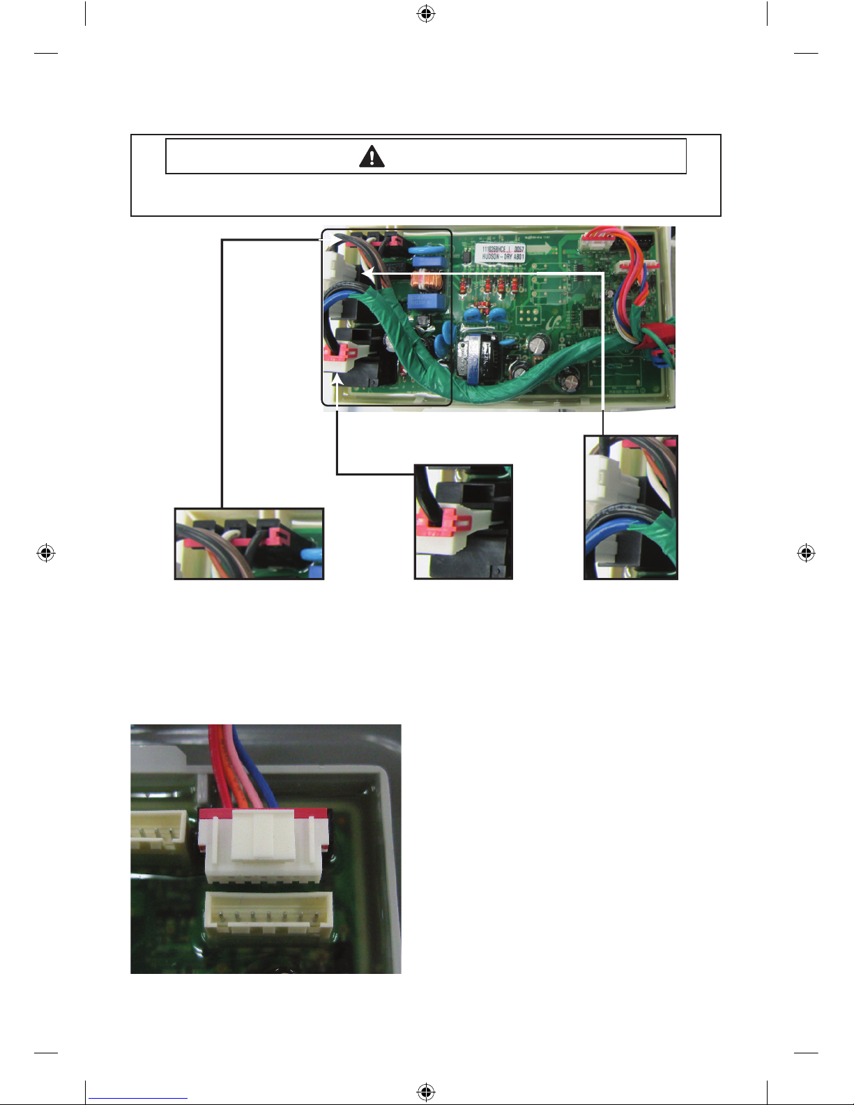
Sensor Bars & temperature sensor check
Sensor Bars - Disconnect harness and test Pink
wire Pin 4 to Orange wire Pin 5.
Approx ∞ Ω without laundry
Approx 190Ω ± 10% with wet clothes
Cycling Thermostat - Disconnect harness and test
Blue wire Pin 3 to Red wire Pin 6.
Approx 10 KΩ at 25 °C/77 °F
CN1
1. AC Power Port
2. Door Detection Sensor
3. Motor Switch Sensor
RY7
- Heater Relay Switch
RY5
- Motor Relay Switch
[HUDSON]_Technical_information-03171A_EN.indd 10 2012-02-03 �� 5:01:24
Page 11
11
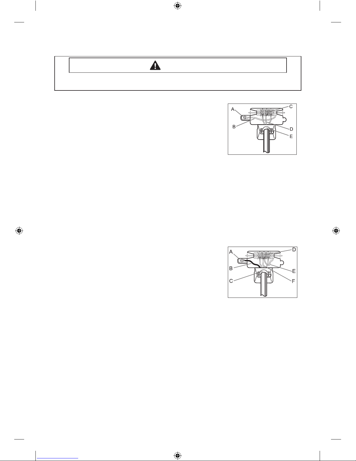
3-WIRE system connections
A. External ground connector
B. Neutral grounding wire (green/yellow)
C. Center silver-colored terminal block screw
D. Neutral wire (white or center wire)
E. ¾” (1.9 cm) UL-listed strain relief
1. Loosen or remove the center terminal block screw.
2. Connect the neutral wire (white or center wire) of the power cord to the center, silvercolored terminal screw of the terminal block. Tighten screw.
3. Connect the other wires to outer terminal block screws. Tighten screws.
4. Tighten the strain relief screws.
5. Insert the tab of the terminal block cover into your Dryer’s rear panel slot.
Secure the cover with a hold-down screw.
If converting from a 4-wire electrical system to a 3-wire, the ground strap must be
reconnected to the terminal block support to ground the Dryer frame to the neutral
conductor.
4-WIRE system connections
A. External ground connector
B. Green or bare copper wire of power cord
C. ¾” (1.9 cm) UL-listed strain relief
D. Center silver-colored terminal block screw
E. Neutral Grounding wire (green/yellow)
F. Neutral wire (white or center wire)
1. Remove the External ground connector screw.
2. Connect the ground wire (green or unwrapped) of the power cord to the external
ground connector screw. If you want to connect B(Green or bare copper wire of power
cord) to the Neutral Post without assembling with A(cabinet ground), call the service
technician.
3. Loosen or remove the center terminal block screw.
4. Connect the neutral wire (white or center wire) of the power cord and the appliance
ground wire (green with yellow stripes) under the central screw of the terminal block.
5. Connect the other wires to the outer terminal block screws. Tighten screws.
6. Tighten the strain relief screws.
7. Insert the tab of the terminal block cover into your Dryer’s rear panel slot.
Secure the cover with a hold-down screw.
TROUBLE SHOOTING
WARNING
To avoid risk of electrical shock, personal injury or death; disconnect power to dryer before
servicing, unless testing requires power.
[HUDSON]_Technical_information-03171A_EN.indd 11 2012-02-03 �� 5:01:24
Page 12
12
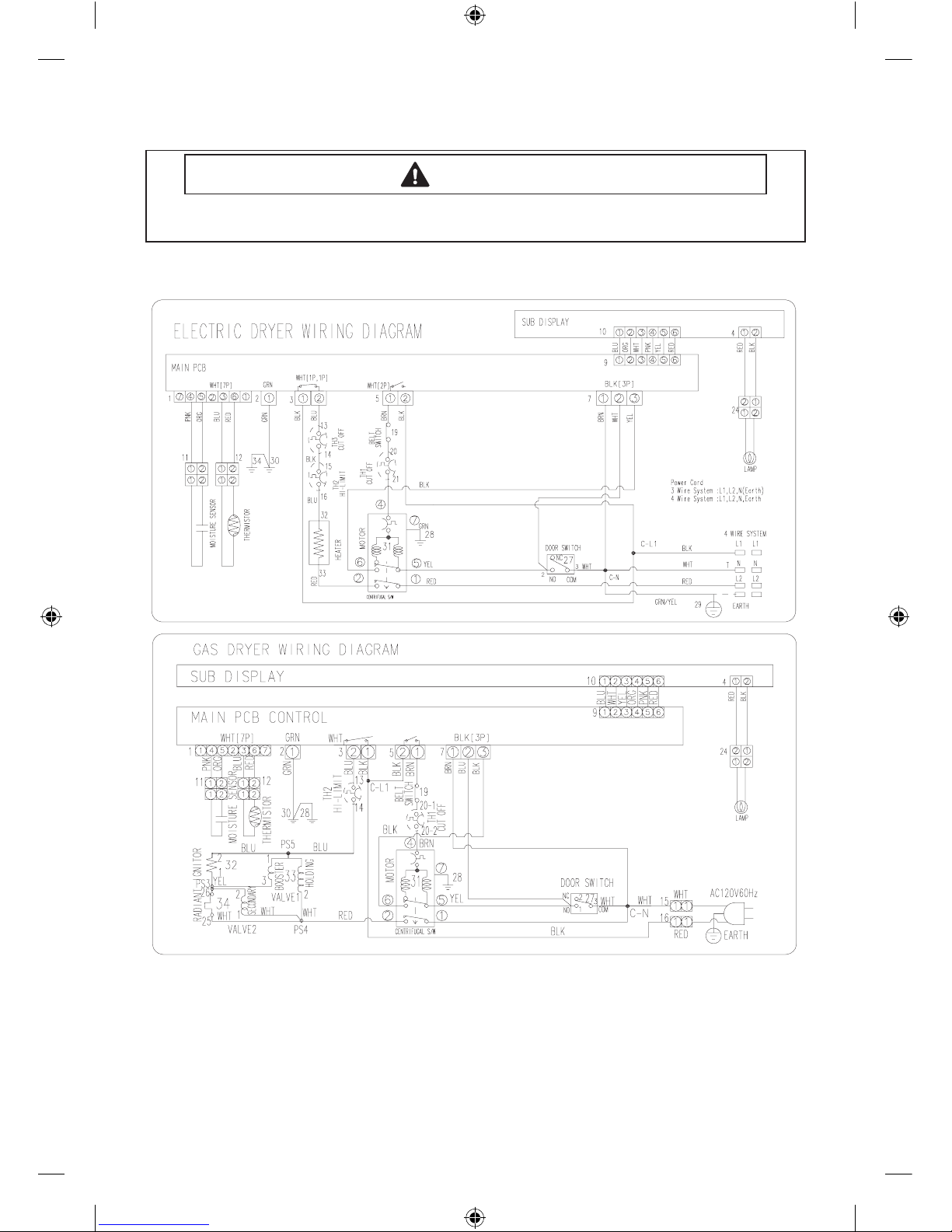
WIRING DIAGRAM
WIRING DIAGRAM
WARNING
To avoid risk of electrical shock, personal injury or death; disconnect power to dryer before
servicing, unless testing requires power.
[HUDSON]_Technical_information-03171A_EN.indd 12 2012-02-03 �� 5:01:24
 Loading...