

Samsung DV395ETPAWR/A1-00 Owner’s Manual
the possibilities
Thank you for purchastng thts SanqsLiiqg product
To receb'e more complete sePJice or accessory
parts please regtster your product at or
contact
www.samsung.com/register
1-8_J0-SAMSUNG _726-7864/
f tLAr S
1. Extra Large Capacity
Ultra drying capabilities are at your fingertips! Now you can dry extra-large loads. Our ultra
large 7.4 cu.ft, capacity dryer circulates more air through your clothes, drying them faster for
a wrinkle-free result.
2. Smart Care (DV405* Only)
Samsung's Smart Care, an automatic error-monitoring system, detects and diagnoses
problems at an early stage and provides quick and easy solutions.
3. Steam cycle
This cycle sprays a small amount of water into the dryer drum after several minutes of
tumbling with heat. It reduces bad odors from clothing that are difficult to remove when
washing with water, and also reduces wrinkles.
4. Sanitize Cycle
This cycle sanitizes garments by infusing high temperature heat deep into the fabric during
the drying cycle and eliminating 99.9% of certain bacteria. Use this cycle for clothing,
bedding, towels, or other items needing sanitization. The Sanitize cycle is certified by NSF
International, an independent third-party testing and certification organization.
_S_ NSF Protocol P154
Sanitization Performance of
Residential C]othes Dryers
5. Various Drying Cycles & Fuzzy Logic Algorithm
Simply turn the Jog Dial to select one of the 13 automatic drying cycles, including normal,
heavy duty and towels, or let the Fuzzy Logic Control measure the degree of dampness and
automatically set the drying time. Precision drying has never been easier than with Samsung.
6. Time Saving
Our cycles are designed with you in mind. All our dryers are designed to dry your clothes in
less time.., just 42 minutes! Giving you time for more important things in life.
7. Energy Saving
Samsung dryers are super energy efficient. You can dry up to 3.01 pounds of laundry with
1kWh. Also, both the large capacity and Fuzzy Logic Control save energy by automatically
drying your clothes the most efficient way.
8. Easy Reversible Door
Our dryers will fit just about anywhere. The direction of our easy reversible door can be
changed easily and quickly.
9. Pedestal with Storage Drawers
An optional 15" pedestal is available to raise the dryer for easier loading and unloading. It
also offers a built-in storage drawer that can hold a 100 oz. bottle of detergent
10.Stacking (MODEL NO: SK-5A/XAA)
Samsung's Washers and Dryers can be stacked to maximize usable space.
The Dryer legs need to be removed to stack the Washer and Dryer. You can purchase an
optional stacking kit from your Samsung retailer.
11.4-way Vent (electric model only)
You can install the exhaust vent in the following four (4) positions: back, either side, bottom.
2 Features
safe nstrLActons
J
Congratulations on your new Samsung Dryer. This manual contains valuable
information on the installation, use, and care of your appliance. Please take the
time to read this manual to take full advantage of your dryer's many benefits and
features.
WARNING - Risk of Fire
• Clothes dryer installation must be performed by a qualified installer.
Install the clothes dryer according to the manufacturer's instructions and local codes.
Do not install a clothes dryer with flexible plastic venting materials. If flexible metal
(foil type) duct is installed, it must be of a specific type identified by the appliance
manufacturer as suitable for use with clothes dryers. Flexible venting materials are
known to collapse, be easily crushed, and trap lint. These conditions will obstruct
clothes dryer airflow and increase the risk of fire.
To reduce the risk of severe injury or death, follow all installation instructions.
WHAT YOU NEED TO KNOW ABOUT SAFETY INSTRUCTIONS
Warnings and Important Safety Instructions in this manual do not cover all possible conditions and
situations that may occur. It is your responsibility to use common sense, caution, and care when installing,
maintaining, or operating your dryer.
Always contact your manufacturer about problems or conditions you do not understand.
IMPORTANT SAFETY SYMBOLS AND PRECAUTIONS
Hazards or unsafe practices that may result in severe personal injury or
death.
WARNING
CAUTION
Follow the information in this manual to minimize the risk of fire or explosion or
to prevent property damage, personal injury, or death.
Do not store or use gasoline or other flammable vapors and liquids near this or
any other appliance.
Hazards or unsafe practices that may result in minor personal injury or
property damage.
Do NOT attempt.
Do NOT disassemble.
(_ Do NOT touch.
Follow directions explicity.
Unplug the power plug from the wall socket.
Make sure the machine is grounded to prevent electric shock.
Call the service center for help.
SAVE THESE INSTRUCTIONS
Safety information 3
J
IMPORTANT SAFTY INSTRUCTION
/_ WARNING: To reduce the risk of fire, electric shock, or injury to persons when using your
......._ appliance, follow basic precautions, including the following:
1. Read all instructions before using this appliance.
2. Do not dry articles that have been previously cleaned in,washed in, soaked in, or spotted with
gasoline, dry-cleaning solvents, or other flammable or explosive substances, as they give off
vapors that could ignite or explode.
3. Do not use the dryer to dry clothes which have traces of any flammable substance, such as
vegetable oil, cooking oil, machine oil, flammable chemicals, thinner, etc., or anything containing
wax or chemicals, such as mops and cleaning cloths. Flammable substances may cause the
fabric to catch fire by itself.
4. Do not store or usegasoline or other flammable vapors and liquids near this or any other
appliance.
5. Do not allow children to play on or in the appliance. Close supervision of children is necessary
when the appliance is used near children.
6. Before the appliance is removed from service ordiscarded, remove the door to the drying
compartment.
7. Do not reach into the appliance if the drum is moving.
8. Do not install or store this appliance where it will be exposed to the weather.
9. Do not tamper with controls.
10. Do not repair or replace any part of the appliance or attempt any servicing unless specifically
recommended in the user-maintenance instructions or in published userrepair instructions that
you understand and have the skills to carry out.
11. Do not use fabric softeners or products to eliminate static unless recommended bythe
manufacturer of the fabric softener or product.
12. Clean the lint screen before or after each load.
13. Do not use heat to dry articles containing foam rubber or similarly textured rubber-like materials.
14. Keep area around the exhaust opening and adjacent surrounding areas free from the
accumulation of lint, dust, and dirt.
15. The interior of the appliance and exhaust duct should be cleaned periodically by qualified service
personnel.
16. Do not place items exposed to cooking oils in your dryer. Items contaminated with cooking oils
may contribute to a chemical reaction that could cause a load to catch fire.
17. This appliance must be grounded. See "Electrical requirements" and "Grounding" in installing your
dryer section.
State of California Proposition 65 Warnings:
WARNIN_
The California Safe Drinking Water and Toxic Enforcement Act requires the Governor of California to
publish a list of substances known to the State of California to cause cancer, birth defects, or other
reproductive harm, and requires businesses to warn of potential exposure to such substances.
This product contains a chemical known to the State of California to cause cancer, birth defects, or
other reproductive harm. This appliance can cause low-level exposure to some of the substances
listed, includingbenzene, formaldehyde, and carbon monoxide.
Gas appliances may cause low-level exposure to some of the substances listed including benzene,
formaldehyde, carbon monoxide, and soot; as a result of possible incomplete combustion of natural
gas or LP fuels. Exposure to these substances can be minimized further by properly venting the dryer
to the outdoors.
SAVE THESE INSTRUCTIONS
4 Safety infol'mation
WHAT TO DO IF YOU SMELL GAS:
Do not try to light any appliance.
Do not turn on the appliance.
Do not touch any electrical switch.
Do not use any phone in your building.
Clear the room, building or area of all occupants.
Immediately call your gas supplier from a neighbor's phone. Follow the gas supplier's
instructions.
If you cannot reach your gas supplier, call the fire department.
Installation and service must be performed by a qualified installer, service agency, or the gas
supplier.
_Read all instructions before the
To reduce the risk of fire or explosion:
WARNINe
Do not dry items that have been previously cleaned, washed, soaked, or spotted with
gasoline, dry cleaning solvents, or other flammable or explosive substances. They
emit vapors that could ignite or explode. Any material that has been in contact with a
cleaning solvent or flammable liquids or solids should not be placed inthe dryer until all
traces of these flammable liquids or solids and their fumes have been removed.
There are many highly flammable items used in homes, such as acetone, denatured
alcohol, gasoline, kerosene, some liquid household cleaners, some spot removers,
turpentine, waxes, and wax removers
Items containing foam rubber (may be labeled latex foam) or similarly textured rubber-
like materials must not be dried on a heat setting. Heated foam rubber materials can,
under certain circumstances, produce fire by spontaneous combustion.
Do not allow children or pets to play on, in, or in front of the appliance. Close supervision is
necessary when the appliance is used near children and pets.
Before discarding or removing your dryer from service, remove the door to the drying
compartment to prevent children or animals from becoming trapped inside.
Do not reach into the appliance when the drum is moving.
Q
Do not install or store this appliance where it will be exposed to the weather.
Do not tamper with controls.
using appliance.
Do not repair, replace, or attempt to service any part of the appliance unless specifically
recommended in the user-repair instructions and you understand and have the skills to
carry those out.
Do not use fabric softeners or products to eliminate static unless recommended for dryer
use by the manufacturer of the fabric softener or product.
Clean the lint screen before or after each load.
Keep the area around the exhaust opening and surrounding areas free from lint, dust, and
dirt.
SAVE THESE INSTRUCTIONS
Safety information 5
n tnA tion
J
The interior of the dryer and exhaust duct should be cleaned periodically by qualified service
personnel.
This appliance must be properly grounded. Never plug the power cord into a receptacle
that is not grounded adequately and in accordance with local and national codes. See
installation instructions for grounding this appliance.
Do not sit on top of the dryer.
Because of continuing product improvements, Samsung reserves the right to change
specifications without notice. For complete details, see the Installation Instructions
packed with your product before selecting cabinetry, making cutouts, or beginning
installation.
Ensure pockets are free from small irregularly shaped hard objects, foreign material, etc. ie.
....... coins, knives, pins, etc. These objects could damage your dryer.
Do not wash clothing with large buckles, buttons, or other heavy metal or solid things.
Gas leaks may occur in your system, resulting in a dangerous situation.
WARNIN_
Gas leaks may not be detected by smell alone.
Gas suppliers recommend you purchase and install a UL-approved gas detector.
Install and use in accordance with the manufacturer's instructions.
Do not place items in your dryer that have been spotted or soaked with vegetable oil or
cooking oil. Evenafter being washed, these items may contain significant amounts of these
oils.
Residual oil on clothing can ignite spontaneoulsy. The potential for spontaneous
combustion increases when items containing vegetable oil or cooking oil are exposed to
heat. Heat sources such as your dryer can warm these items, allowing an oxidation reaction
in the oil to occur. Oxidation creates heat. If this heat cannot escape, the items can become
hot enough to catch fire. Piling, stacking, or storing these kinds of items may prevent heat
from escaping and can create a fire hazard.
All washed and unwashed fabrics that contain vegetable oil or cooking oil can be
dangerous. Washing these items in hot water with extra detergent will reduce, but not
eliminate, the hazard. Always use the Cool Down cycle for these items to reduce their
temperature. Never remove these items from the dryer hot or interrupt the drying cycle until
the items have run through the Cool Down cycle. Never pile or stack these items when they
are hot.
6 Safety infolmation
SAVE THESE INSTRUCTIONS
content,
iNSTALLiNG YOUR DRYER
OPERATING iNSTRUCTiONS, TIPS
CARE AND CLEANING
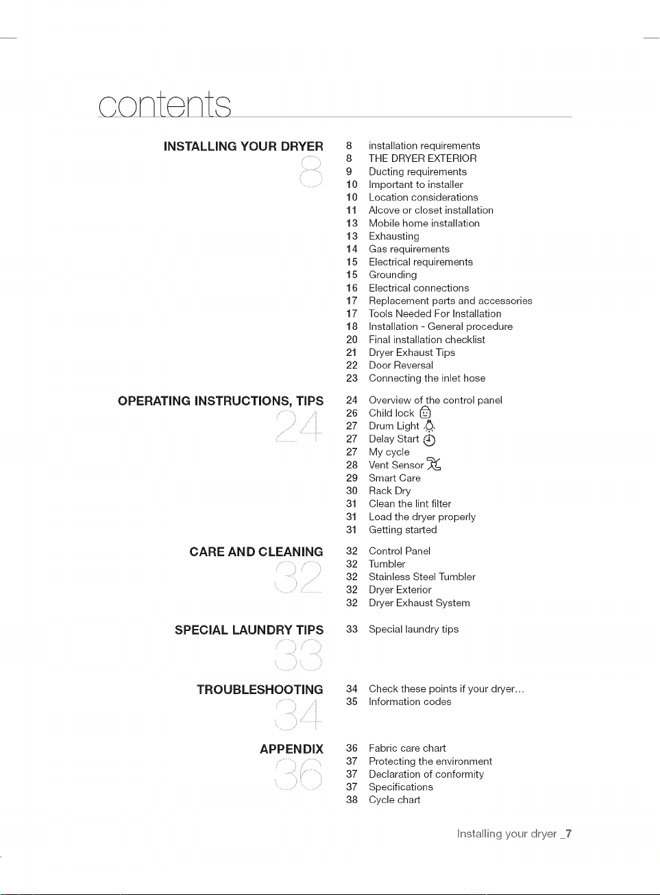
8 installation requirements
8 THE DRYER EXTERIOR
9 Ducting requirements
10 Important to installer
10 Location considerations
11 Alcove or closet installation
13 Mobile home installation
13 Exhausting
14 Gas requirements
15 Electrical requirements
15 Grounding
16 Electrical connections
17 Replacement parts and accessories
17 Tools Needed For Installation
18 Installation - General procedure
20 Final installation checklist
21 Dryer Exhaust Tips
22 Door Reversal
23 Connecting the inlet hose
24 Overview of the control panel
26 Child lock 1_
27 Drum Light -,.0,-
ii
27 Delay Start
27 My cycle
28 Vent Sensor
29 Smart Care
30 Rack Dry
31 Clean the lint filter
31 Load the dryer properly
31 Getting started
32 Control Panel
32 Tumbler
32 Stainless Steel Tumbler
32 Dryer Exterior
32 Dryer Exhaust System
SPECIAL LAUNDRY TIPS
TROUBLESHOOTING
APPENDIX
33 Special laundry tips
34 Check these points if your dryer...
35 Information codes
36 Fabric care chart
37 Protecting the environment
37 Declaration of conformity
37 Specifications
38 Cycle chart
Installing your_drye__7
iNSTALLATiON REQUIREMENTS
Hire a professional to install this dryer properly. If there is a service call performed as a result of poor setup,
adjustment, and connection, it is considered the responsibility of the installer. If you install the dryer, you are
responsible.
Make sure you have everything necessary for proper installation.
t. A GROUNDED ELECTRICAL OUTLET is required. See Electrical Requirements.
2. A POWER CORD for electric dryers (except Canada).
3. GAS LINES (if you have a gas dryer) must meet national and local codes.
4. EXHAUST SYSTEM - must be rigid metal or flexible stiff-walled metal exhaust ducting.
See the exhaust requirements on pages 8-10.
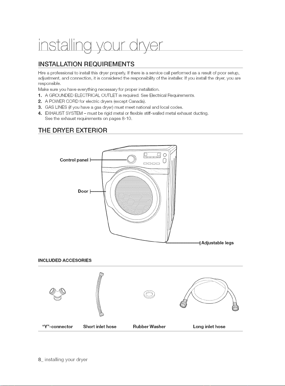
THE DRYER EXTERIOR
Control panel
Door
Adjustable legs
INCLUDED ACCESORIES
"Y"-connector Short inlet hose Rubber Washer Long inlet hose
8 installing your dryer
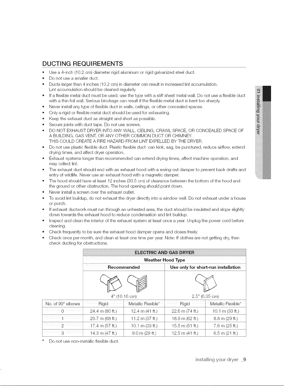
DUCTING REQUIREMENTS
Use a 4-inch (10.2 cm) diameter rigid aluminum or rigid galvanized steel duct.
Do not use a smaller duct.
Ducts larger than 4 inches (10.2 cm) in diameter can result in increased lint accumulation.
Lint accumulation should be cleaned regularly.
If a flexible metal duct must be used, use the type with a stiff sheet metal wall. Do not use a flexible duct
with a thin foil wall. Serious blockage can result if the flexible metal duct is bent too sharply.
Never install any type of flexible duct in walls, ceilings, or other concealed spaces.
Only a rigid or flexible metal duct should be used for exhausting.
Keep the exhaust duct as straight and short as possible.
Secure joints with duct tape. Do not use screws.
DO NOT EXHAUST DRYER INTO ANY WALL, CEILING, CRAWL SPACE, OR CONCEALED SPACE OF
A BUILDING, GAS VENT, OR ANY OTHER COMMON DUCT OR CHIMNEY.
THIS COULD CREATE A FIRE HAZARD FROM LINT EXPELLED BY THE DRYER.
Do not use plastic flexible duct. Plastic flexible duct can kink, sag, be punctured, reduce airflow, extend
drying times, and affect dryer operation.
Exhaust systems longer than recommended can extend drying times, affect machine operation, and
may collect lint.
The exhaust duct should end with an exhaust hood with a swing-out damper to prevent back drafts and
entry of wildlife. Never use an exhaust hood with a magnetic damper.
The hood should have at least 12 inches (30.5 cm) of clearance between the bottom of the hood and
the ground or other obstruction. The hood opening should point down.
Never install a screen over the exhaust outlet.
To avoid lint buildup, do not exhaust the dryer directly into a window well. Do not exhaust under a house
or porch.
If exhaust ductwork must run through an unheated area, the duct should be insulated and slope slightly
down towards the exhaust hood to reduce condensation and lint buildup.
Inspect and clean the interior of the exhaust system at least once a year. Unplug the power cord before
cleaning.
Check frequently to be sure the exhaust hood damper opens and closes freely.
Check once per month, and clean at least one time per year. Note: If clothes are not getting dry, then
check ducting for obstructions.
Weather Hood Type
No. Of 90 ° elbows Rigid Metallic Flexible*
3 14.3 m (47 ft.) 9.0 m (29 ft.)
* Do not use non-metallic flexible duct.
i
24.4 m (80 ft.) 12.4 m (41 ft.)
20.7 m (68 ft.) 11.2 m (37 ft.)
17.4 m (57 ft.) 10.1 m (33 ft.)
4" (10.16 cm)
use 0.iv forsho_-ru, i,,stallatio,,
2.5" (6.35 cm)
Rigid Metallic Flexible _
22.6 m (74 ft.) 10.1 m (33 ft.)
18.9 m (62 ft.) 8.8 m (29 ft.)
15.5 m (51 ft.) 7.6 m (25 ft.)
12.5 m (41 ft.) 6.5 m (21 ft.)
installing your dryer 9
If the new dryer is installed into an existing exhaust system you must make
sure:
• The exhaust system meets all local, state, and national codes.
• That a flexible plastic duct is not used.
• To Inspect and clean all lint buildup from inside the existing duct.
• The duct is not kinked or crushed.
• The exhaust hood damper opens and closes freely.
The static pressure in any exhaust system must not exceed 0.83 inches of water column, or be
less than 0.
This can be measured with the dryer running with a manometer at the point where the exhaust
duct connects to the dryer. A no-heat setting should be used. The dryer tumbler should be
empty and the lint filter clean.
IMPORTANT TO INSTALLER
Please read the following instructions carefully before installing the dryer. These instructions should be kept
for future reference.
A REMOVE THE DOOR FROM ALL DISCARDED APPLIANCES TO AVOID THE DANGER OF A CHILD
....... SUFFOCATING.
LOCATION CONSI DERATIONS
The dryer should be located where there is enough space at the front for loading the dryer, and enough
space behind for the exhaust system. This dryer is factory-ready for rear exhaust. To exhaust out the
bottom or the right or the left, use the accessory exhaust kit. Instructions are included with the kit. It's
important to make sure the room has enough fresh air. The dryer must be located where there is no air-flow
obstruction.
On gas dryers, adequate clearance as noted on the data plate must be maintained to ensure adequate air
for combustion and proper dryer operation.
THE DRYER MUST NOT BE INSTALLED OR STORED IN AN AREA WHERE IT WILL BE EXPOSED TO
WATER AND/OR WEATHER. THE DRYER AREA IS TO BE KEPT CLEAR OF COMBUSTIBLE MATERIALS,
GASOLINE, AND OTHER FLAMMABLE VAPORS AND LIQUIDS. A DRYER PRODUCES COMBUSTIBLE
LINT. THE AREA AROUND THE DRYER SHOULD BE KEPT LINT-FREE.
10 installing your ' dryer
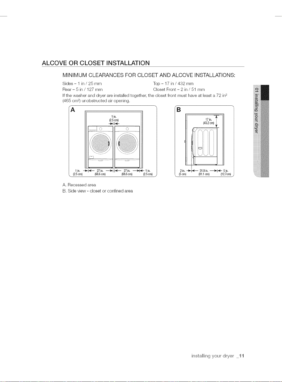
ALCOVE OR CLOSET INSTALLATION
MINIMUM CLEARANCES FOR CLOSET AND ALCOVE INSTALLATIONS:
Sides - 1 in / 25 mm Top - 17 in / 432 mm
Rear- 5 in / 127 mm Closet Front - 2 in / 51 mm
If the washer and dryer are installed together, the closet front must have at least a 72 in2
(465 cm 2) unobstructed air opening,
A
1in.
(2.5cm)
-_t I_-
O
B
17in.
(43.2cm)_,_
1in. --_-I_ - 27in. _11_--- 27in. _lin.
(2.5cm) (68.6cm) (6&6cm) (2.5cm)
A. Recessed area
B. Side view - closet or confined area
2 in. -_1 _-- 31.9in. _1_[ - 5 in.
(5cm) (81.1cm) (12.7cm)
installing your dryer 11
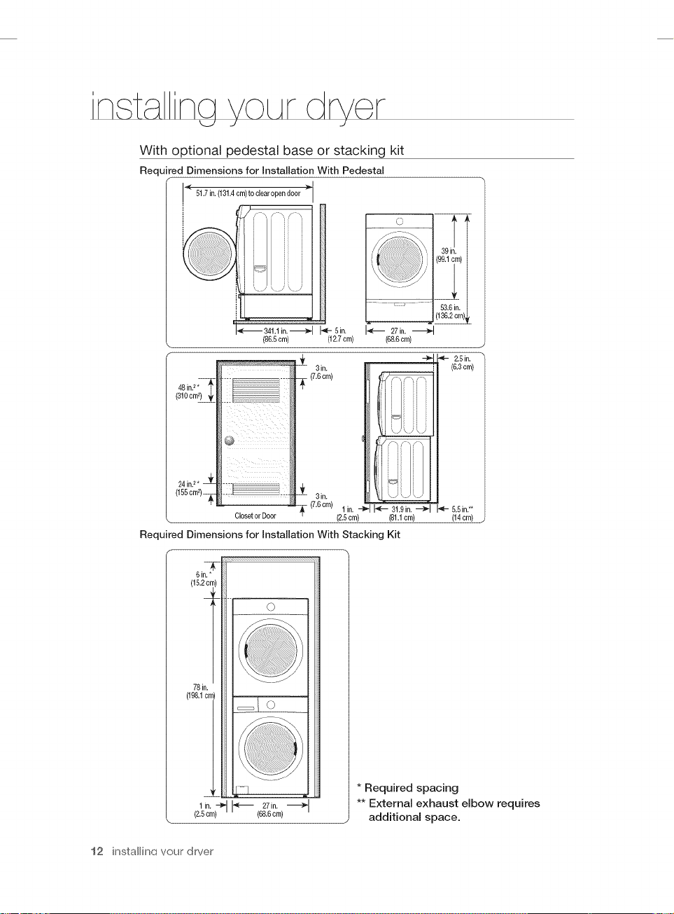
With optional pedestal base or stacking kit
Required Dimensions for installation With Pedestal
< 61.7in.(131.4cm)toclearopen door ;_
i
48in.2*_
_ 341.1 in. _
@
(86.6era)
I'_- 5 in.
J:
3in.
_- (7.6cm)
(12.7cm)
27in,
(68.6cm)
C' &
39in.
(99,1cm)
....... 53.6in.
_ (136.2cm) L
2.5in,
(6,3cm)
24 in.2. _
(166om_)_
Required Dimensions for Installation With Stacking Kit
6in,*
(16.2 cn
78in.
(198.1c_
(2.6cm)
12 instalfin(_ your dryer
b
1in. -_
ClosetorDoor
0
I_ 27in.
(88,6cm)
3in.
1 in. _ _ 31.9in. --_1 _ 6.6in.**
(7.6cm)
(2.6cm) (81.1cm) (14cm)
* Required spacing
** External exhaust elbow requires
additional space.
MOBILE HOME INSTALLATION
The installation of the dryer in mobile homes must conform to the Manufactured Home Construction and
Safety Standard Title 24 CFR, Part 3280 {formerly the Federal Standard for Mobile Home Construction and
Safety, Title 24, HUD (Part 280), 1975} for the United States) or CSA Standards Z240 (for Canada).
When installing a dryer in a mobile home, provisions for anchoring the dryer to the floor must be made.
Locate an area that has adequate fresh air.
A minimum of 72 in2 (465 cm 2) of unobstructed space is required.
Call 1-800-SAMSUNG (726-7864) for information on purchasing the Floor Anchoring Kit as an accessory.
All mobile home installations must be exhausted to the outside with the exhaust duct termination securely
fastened to the mobile home structure, using materials that wiii not support combustion.
The exhaust duct may not terminate underneath the mobile home.
See Exhausting section for more information.
EXHAUSTING
The dryer shall not be exhausted into a chimney, a wall, a ceiling, an attic, a crawl space, or a concealed space of a
building.
Exhausting the dryer to the outside will prevent large amount of lint and moisture from being blown into the room.
in the United States:
" All dryer must be exhausted to the outside.
,, The required exhaust duct is 4 inches(10.2 cm ) in diameter.
,, Use only those foil-type flexible ducts, if any, specifically indentified for use with the appliance
by the manufacturer and that comply with the Outline for Clothes Dryer Transition Duct,
Subject 2158A, shall be used.
,, See "Ducting Requirements" in installing your dryer section for the maximum duct length and
number of bends.
,, The total length of flexible metal duct shall not exceed 2.4m.
,, Do not assemble the duct with screws or other fastening means that extend into the duct
and catch lint.
In
Canada:
®
All dryer must be exhausted to the outside.
®
The exhaust duct should be 4 inches(10.2 cm ) in diameter.
®
Use only those foil-type flexible ducts, if any, specifically indentified for use with the appliance
by the manufacturer shall be used.
See "Ducting Requirements" in installing your dryer section for the maximum duct length and
number of bends.
The total length of flexible metal duct shall not exceed 2.4m.
Do not assemble the duct with screws or other fastening means that extend into the duct
and catch lint.
Outside the U.S. and Canada:
" Refer to the local codes.
i_X The dryer must be exhausted to the outside to reduce the risk of fire when installed in an
w,_.._._alcove or closet.
NEVER USE A PLASTIC OR NON-METAL FLEXIBLE DUCT.
If your existing ductwork is plastic, non-metal, or combustible, replace it with metal.
Use only a metal exhaust duct that is non-flammable to ensure containment of exhaust air,
heat, and lint.
installing your dryer 13
GAS REQUIREMENTS
Use only natural or LP (liquid propane) gases.
THE INSTALLATION MUST CONFORM WITH LOCAL CODES, OR IN THE ABSENCE OF LOCAL
CODES, WITH THE NATIONAL FUEL GAS CODE ANSVZ223.1, LATEST REVISION (FOR THE UNITED
STATES), OR WITH THE CAN/CGA-B149 INSTALLATION CODES (FOR CANADA).
Gas dryers are equipped with a burner vent for use with natural gas. If you plan to use your dryer with LP
(liquid propane) gas, it must be converted for safe and proper performance by a qualified service technician.
A 1/2" (1.27 cm) gas supply line is recommended and must be reduced to connect to the 3/8" (1 cm) gas
line on your dryer. The National Fuel Gas Code requires that an accessible, approved manual gas shut-off
valve be installed within G" of your dryer.
Gas dryers installed in residential garages must be raised 18 inches (46 cm) above the floor.
Additionally, a 1/8" (0.3 cm) N.RT. (National Pipe Thread) plugged tapping, accessible for test gauge
connection, must be installed immediately upstream of your dryer's gas supply connection.
Your dryer must be disconnected from the gas supply pipe system during any pressure testing of the
system.
DO NOT reuse old flexible metal gas lines. Flexible gas lines must be design certified by the American Gas
Association (CGA in Canada).
(_ ny pipe joint compound used must be resistant to the action of any liquefied petroleum gas.
As a courtesy, most local gas utilities will inspect a gas appliance installation.
GAS IGNITION - Your dryer uses an automatic ignition system to ignite the burner.
There is no constant burning pilot.
Commonwealth of Massachusetts installation instructions
Your dryer must be installed by a licensed plumber or gas fitter. A "T" handle manual gas valve
must be installed in the gas supply line to your dryer. If a flexible gas connector is used to install
your dryer, the connector must have a maximum length of 3' (36").
- Gas leaks may occur in your system, creating a dangerous situation.
........ Gas leaks may not be detected by smell alone.
Gas suppliers recommend you purchase and install a UL-approved gas detector.
Install and use in accordance with the manufacturer's instructions.
14 installing your dryer
ELECTRICAL REQUIREMENTS
_The
WARNING
wiring diagram is located on the back of the dryer.
Improperly connecting the equipment grounding conductor can result in a risk of electric shock.
Check with a qualified electrician or serviceman if you are in doubt as to whether your dryer is
properly grounded. Do not modify the plug provided with your dryer - if it doesn't fit the outlet,
have a proper outlet installed by a qualified electrician.
To prevent unnecessary risk of fire, electrical shock, or personal injury, all wiring and grounding
must be done in accordance with local codes, or in the absence of local codes, with the National
Electrical Code, ANSI/NFPA No. 70-Latest Revision (for the U.S.) or the Canadian Electrical Code
CSA C22.1 - Latest Revisions and local codes and ordinances. It is your responsibility to provide
adequate electrical services for your dryer.
All gas installations must be done in accordance with the national Fuel Code ANSI/Z2231 - Latest
Revision (for the U.S.) or CAN/CGA - B149 Installation Codes - Latest Revision (for Canada) and
local codes and ordinances.
GROUNDING
This dryer must be grounded. In the event of malfunction or breakdown, the ground will reduce the risk of
electrical shock by providing a path of least resistance for the electrical current.
Gas models
WARNIN_
Your dryer has a cord with an equipment-grounding conductor and a grounding plug.
The plug must be plugged into an appropriate outlet that is properly installed and grounded in
accordance with all local codes and ordinances.
Do not modify the plug provided with your dryer - if it doesn't fit the outlet, have a proper outlet
installed by a qualified electrician.
NEVER CONNECT GROUND WIRE TO PLASTIC PLUMBING LINES, GAS LINES, OR HOT
WATER PIPES.
Electric models
/k
WARNIN_
Your dryer has a cord with an equipment-grounding conductor and a grounding plug, sold
separately.
The plug must be plugged into an appropriate outlet that is properly installed and grounded in
accordance with all local codes and ordinances.
Do not modify the plug provided with your dryer - if it doesn't fit the outlet, have a proper outlet
installed by a qualified electrician.
If a power cord is not used and the electric dryer is to be permanently wired, the dryer must
be connected to a permanently grounded metal wiring system, or an equipment grounding
conductor must be run with the circuit conductors and connected to the equipment grounding
terminal or lead on the dryer.
installing your dryer 15
ELECTRICAL CONNECTIONS
Before operating or testing, follow all grounding instructions in the Grounding section.
An individual branch (or separate) circuit serving only your dryer is recommended. DO NOT USE AN
EXTENSION CORD.
Gas models- U.S. and Canada
A 120 volt, 60 Hz AC approved electrical service, with a 15-ampere fuse or circuit breaker is
required.
Electric models- U.S. only
Most U.S. dryers require a 120/240 volt, 60 Hz AC approved electrical service. The electric
service requirements can be found on the data label located behind the door. A 30-ampere fuse
or circuit breaker on both sides of the line is required.
• If a power cord is used, the cord should be plugged into a 30-ampere receptacle.
• The power cord is NOT provided with U.S. electric model dryers.
Z_ Risk of Electric Shock:
WARNINe
When local codes allow, the dryer electrical supply may be connected by means of a new power
supply cord kit, marked for use with a dryer, that is U.L. listed and rated at a minimum of120/240
volts, 30-ampere with three No. 10 copper wire conductors terminated with closed loop
terminals, open-end spade lugs with turned up ends, or with tinned leads.
• Do not reuse a power supply cord from an old dryer. The power cord electric supply wiring
must be supported at the dryer cabinet by a suitable UL-listed strain relief.
• Grounding through the neutral conductor is prohibited for (1) new branch-circuit installations,
(2) mobile homes, (3) recreational vehicles, and (4) areas where local codes prohibit
grounding through the neutral conductor. (Use a 4-prong plug for a 4 wire receptacle, NEMA
type 14-30R.)
Electric models - Canada Only
• A 120/240 volt, 60 Hz AC approved electrical service fused through a 30-ampere fuse or
circuit breaker on both sides of the line is required.
• All Canadian models are shipped with the power cord attached. The power cord should be
plugged into a 30-ampere receptacle.
[_lt is not permissible to convert a dryer in Canada to 208 volts.
16 installing your ' dryer
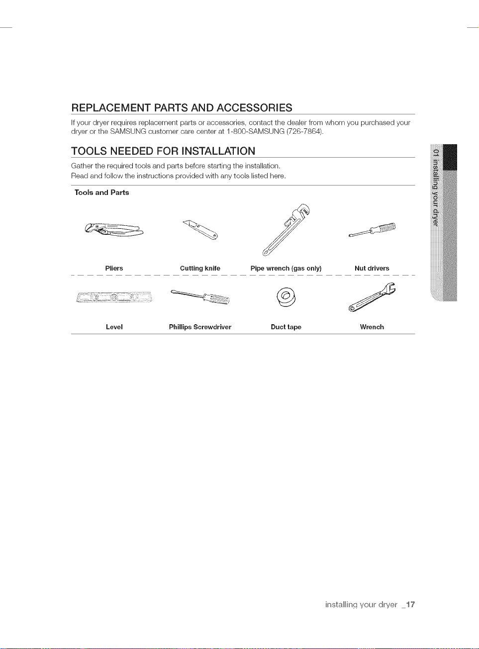
REPLACEMENT PARTS AND ACCESSORIES
If your dryer requires replacement parts or accessories, contact the dealer from whom you purchased your
dryer or the SAMSUNG customer care center at 1-800-SAMSUNG (726-7864).
TOOLS NEEDED FOR iNSTALLATiON
Gather the required tools and parts before starting the installation.
Read and follow the instructions provided with any tools listed here.
Tools and Parts
Pliers Cutting knife Pipe wrench (gas only) Nut drivers
Level
Phillips Screwdriver Duct tape Wrench
installin(_ your dryer 17
INSTALLATION - GENERAL PROCEDURE
For proper installation, we recommend that you hire a qualified installer.
Read these instructions completely before you begin the installation.
To install the dryer, follow these steps:
t. Move your dryer to an appropriate location for installation. Consider installing the dryer and washer side-
by-side so you have easy access to both appliances.
To move the dryer easily, lay two of the carton cushion-tops on the floor. Tip your dryer on its side so it
lies across both cushion-tops. Push the dryer so that it is near its final location. Set your dryer upright.
Leave enough room around the dryer so you can attach the duct work, power cord, etc.
2.
If you need to change the direction of the door, go to Door Reversal on page. When done, return to
Step 3 below.
3.
Review the Exhausting section before installing the exhaust system. Install the duct work from your
dryer to the exhaust hood. The crimped end of the duct sections must point away from your dryer. DO
NOT use sheet metal screws when assembling ducting. These joints should be taped. Never use plastic
flexible exhaust material.
A tip for tight installations: Attach a section of the exhaust system to your dryer before putting it in
place. Use duct tape to secure this section to your dryer, but do not cover the ventilation slots at the
back of the dryer cabinet.
4.
If you have an electric model, skip to Step 6. If you have a gas model, go to the next step.
5.
Review the Gas Requirements section, then follow the lettered steps below.
ao Remove the pipe thread protective cap.
b. Apply pipe joint compound or about 1 1/2 wraps of Teflon tape over all threaded connections.
The pipe joint compound must be resistant to the action of liquefied petroleum
c. Connect the gas supply to your dryer. An additional fitting is required to connect the 3/4" (1.9 cm)
female thread end of a flexible connector to the 3/8" (1 cm) male threaded end on the dryer.
d. Securely tighten the gas line fitting over the threads.
e. Turn on the gas supply. Check all gas connections for leaks using a soap solution. If bubbles
appear, tighten the connections and recheck. DO NOT use an open flame to check for gas leaks.
f. Go to Step 6 on the next page
any gas.
18 installing your' dryer
6. Review the Electrical Requirements section, then follow the 3 Wire system connection instructions (Step
7) or 4 Wire system instructions (Step 8) below.
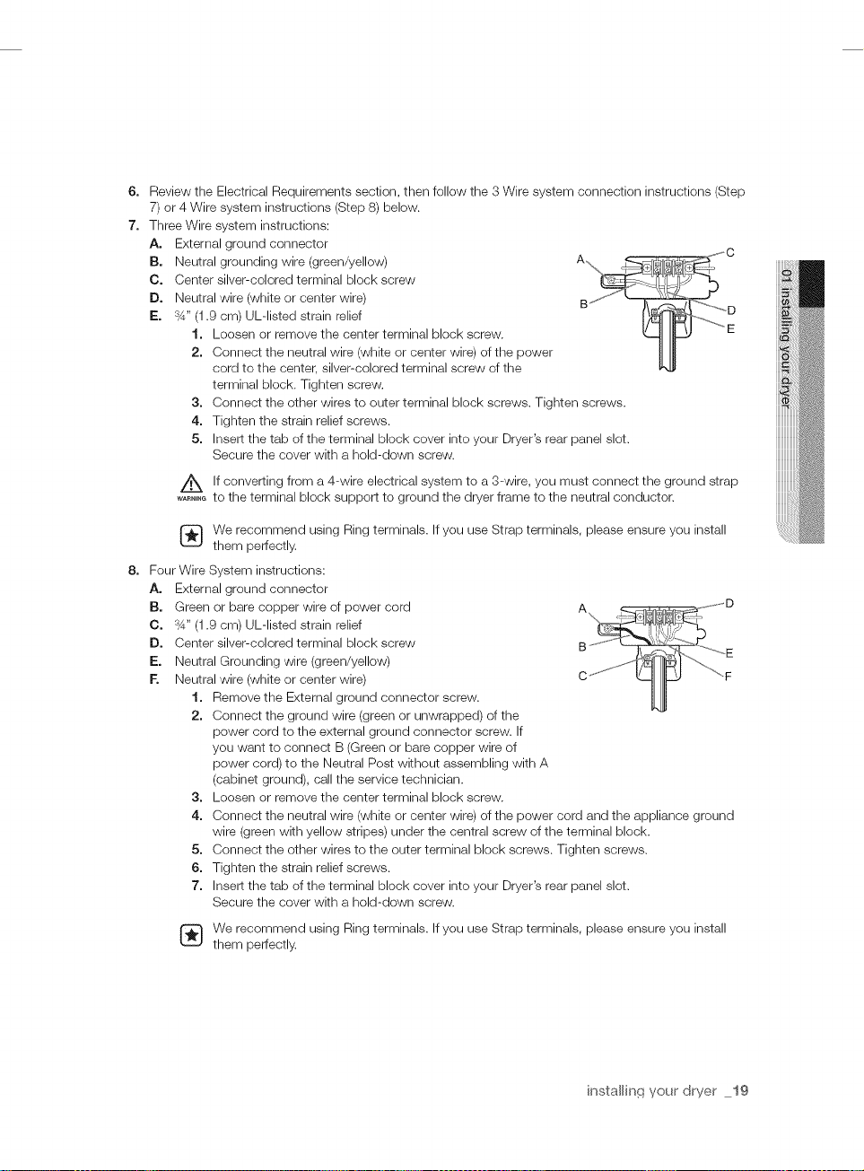
7. Three Wire system instructions:
Ao External ground connector
IBo Neutral grounding wire (green/yellow)
Co Center silver-colored terminal block screw
Do Neutral wire (white or center wire)
I_o %" (1.9 cm) UL-listed strain relief
1. Loosen or remove the center terminal block screw.
2. Connect the neutral wire (white or center wire) of the power
cord to the center, silver-colored terminal screw of the
terminal block. Tighten screw.
3. Connect the other wires to outer terminal block screws. Tighten screws.
4. Tighten the strain relief screws.
5. Insert the tab of the terminal block cover into your Dryer's rear panel slot.
Secure the cover with a hold-down screw.
If converting from a 4-wire electrical system to a 3-wire, you must connect the ground strap
_A_.,._to the terminal block support to ground the dryer frame to the neutral conductor.
We recommend using Ring terminals. If you use Strap terminals, please ensure you install
them perfectly.
8. Four
Wire System instructions:
A.
External ground connector
B.
Green or bare copper wire of power cord
C.
%" (1.9 cm) UL-listed strain relief
D.
Center silver-colored terminal block screw
E.
Neutral Grounding wire (green/yellow)
E
Neutral wire (white or center wire)
1. Remove the External ground connector screw.
2. Connect the ground wire (green or unwrapped) of the
power cord to the external ground connector screw. If
you want to connect B (Green or bare copper wire of
power cord) to the Neutral Post without assembling with A
(cabinet ground), call the service technician.
3. Loosen or remove the center terminal block screw.
4. Connect the neutral wire (white or center wire) of the power cord and the appliance ground
wire (green with yellow stripes) under the central screw of the terminal block.
5. Connect the other wires to the outer terminal block screws. Tighten screws.
6. Tighten the strain relief screws.
7. Insert the tab of the terminal block cover into your Dryer's rear panel slot.
Secure the cover with a hold-down screw.
We recommend using Ring terminals. If you use Strap terminals, please ensure you install
them perfectly.
installin(_ your dryer 19
U.S. MODELS:
A Risk of ElectricShock:
....... All U.S.models areproduced for a 3-WIRE SYSTEM CONNECTION. The dryer frame is grounded to the
neutral conductor at theterminal block. A 4-WIRE SYSTEM CONNECTION is required for new or remodeled
construction, mobile homes, or if localcodes do not permit grounding through neutral. Ifthe 4-wire system is
used, the dryer frame cannot be grounded to theneutral conductor at theterminal block. Refer to the following
instructions for 3- and 4-WIRE SYSTEM CONNECTIONS.
Remove the terminal block cover plate. Insertthe power cord with a UL-listed strain reliefthrough thehole provided in the
cabinet near the terminal block.
A strain reliefmust be used. Do not loosen the nuts alreadyinstalled on the terminal block. Be sure they aretight. Use a 3/8"
(lcm) deep well socket.
9. Connect the Water Inlet Hose. For instructions, go to Connecting the Inlet Hose
on page
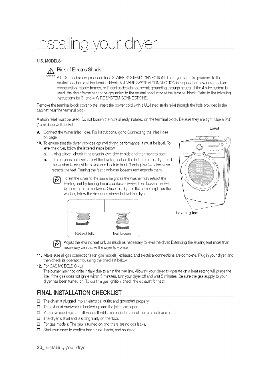
10. To ensure that the dryer provides optimal drying performance, it must be level.To
level the dryer, follow the lettered st_ Dsbelow:
a. Using a level, check ifthe dryer is level side to side and then front to back.
b. If the dryer is not level,adjust the leveling feet on the bottom of thedryer until
the washer is levelside to side and back to front. Turningthe feet clockwise
retracts the feet.Turning the feet clockwise loosens and extends them.
[_ To set the dryer to the same height as the washer, fullyretract the
levelingfeet by turning them counterclockwise, then loosen the feet
by turning them clockwise. Once the dryer is the same heightas the
washer, follow the directions above to levelthe dryer.
Leveling feet
Level
Adjust the leveling feet one/as much as necessary to levelthe dryer Extending theleveling feet more than
necessary can cause the dryer to vibrate.
11. Make sure all gas connections (on gas models), exhaust, and electrical connections are complete. Plug in your dryer,and
then check its operation by using the checklist below.
12. For GAS MODELS ONLY
The burner may not ignite initiallydue to air inthe gas line. Allowing your dryerto operate on a heat setting will purge the
line. Ifthe gasdoes not ignite within 5 minutes, turn your dryeroff and wait 5 minutes. Be sure the gas supply to your
dryer has been turned on. To confirm gas ignition, check the exhaust for heat.
FINAL INSTALLATION CHECKLIST
[] The dryer is plugged into an electrical outlet and grounded proper_/.
[] The exhaust ductwork is hooked up and the joints are taped.
[] You have used rigidor stiff-walled flexiblemetal duct material, not plastic flexibleduct.
[] The dryer is leveland is sitting firmlyon the floor.
[] For gas models: The gas isturned on and there are no gas leaks.
[] Start your dryer to codirm that it runs, heats, and shuts off.
20 installing your' dryer
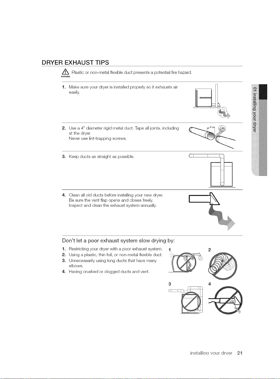
DRYER EXHAUST TiPS
Z_ Plastic or non-metal flexible duct presents a potential fire hazard.
WARNING
1. Make sure your dryer is installed properly so it exhausts air
easily.
2. Use a 4" diameter rigid metal duct. Tape all joints, including
at the dryer.
Never use lint-trapping screws.
3. Keep ducts as straight as possible
4. Clean all old ducts before installing your new dryer.
Be sure the vent flap opens and closes freely.
Inspect and clean the exhaust system annually.
(I I_
Don't let a poor exhaust system slow drying by:
1. Restricting your dryer with a poor exhaust system.
2. Using a plastic, thin foil, or non-metal flexible duct.
3. Unnecessarily using long ducts that have many
elbows.
4. Having crushed or clogged ducts and vent.
1
3
2
4
O
installinq your drver 21
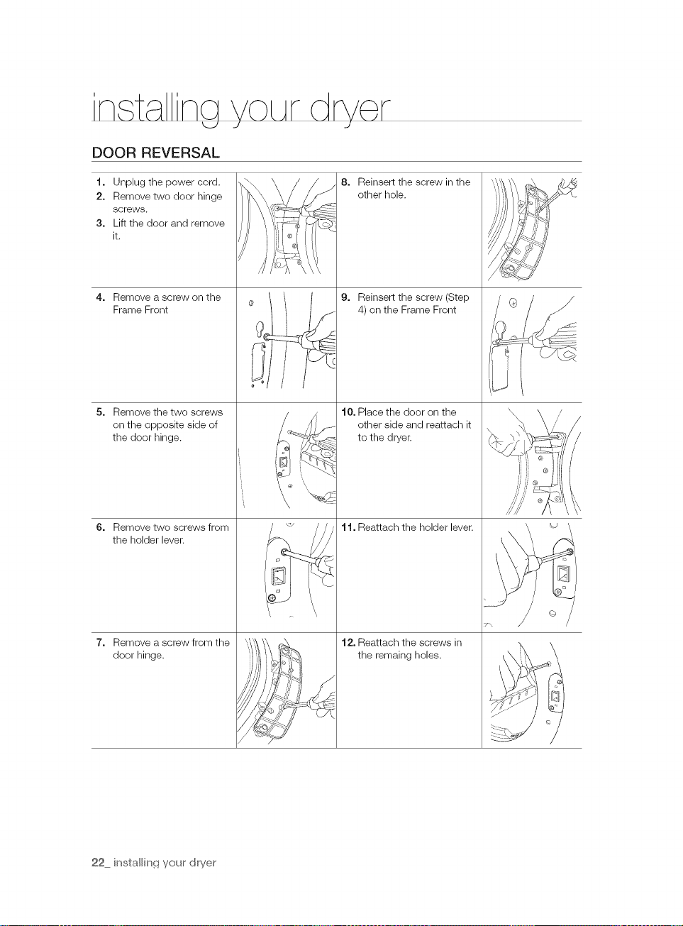
DOOR REVERSAL
t. Unplug the power cord.
2. Remove two door hinge
screws.
3. Lift the door and remove
it,
4. Remove a screw on the
Frame Front
5. Remove the two screws
on the opposite side of
the door hinge.
6. Remove two screws from
the holder lever.
8. Reinsert the screw in the
other hole.
®
9. Reinsert the screw (Step
4) on the Frame Front
10. Place the door on the
other side and reattach it
to the dryer.
1t. Reattach the holder lever.
7. Remove a screw from the
door hinge.
22 installin(_ your' dwer
12. Reattach the screws in
the remaing holes.
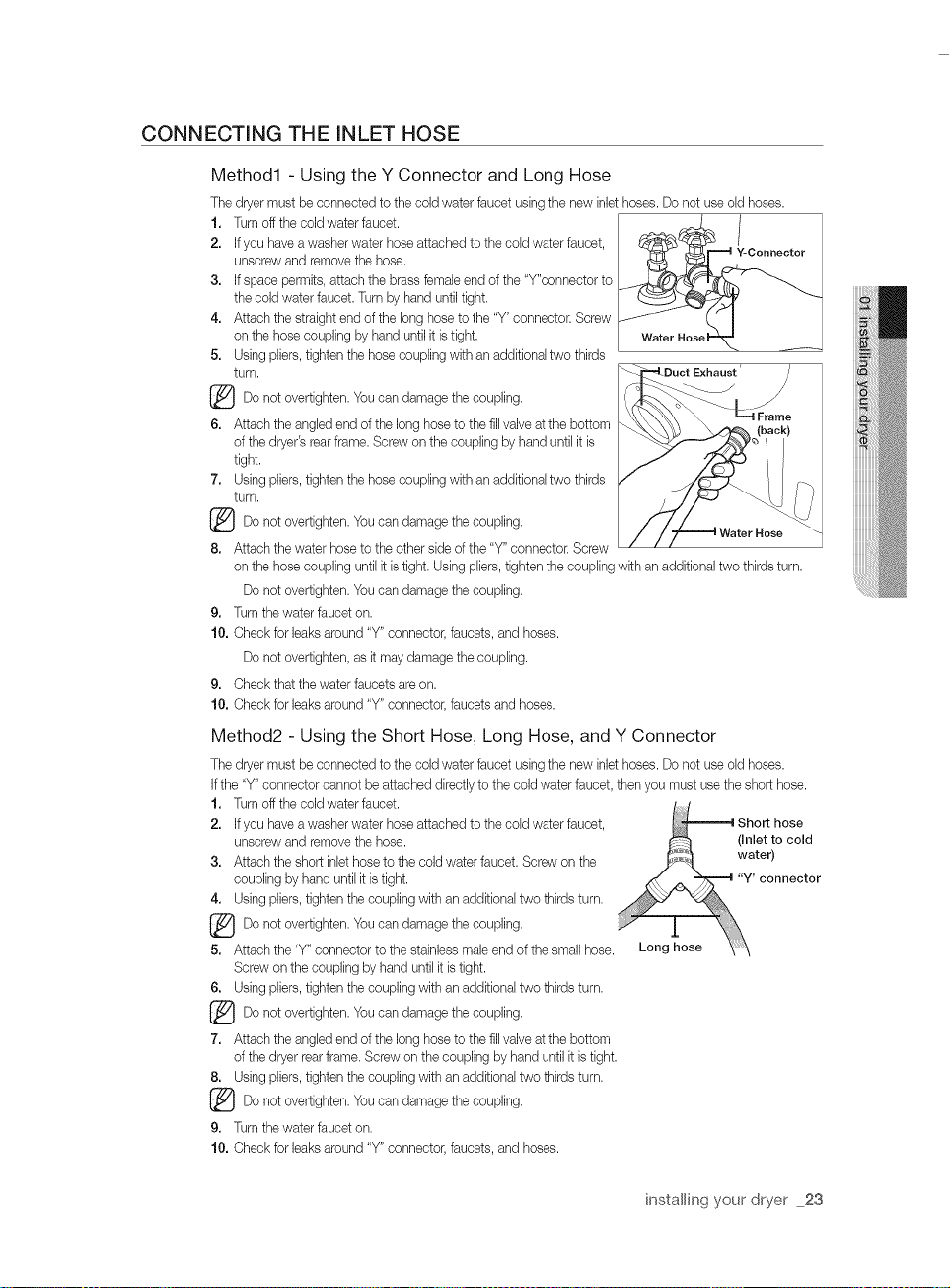
CONNECTING THE INLET HOSE
Method1 - Using the Y Connector and Long Hose
The dryer must be connected to the cold water faucet using the new inlet hoses. Do not use old hoses.
1. Turn off the cold water faucet.
2, Ifyou have a washer water hose attached to the cold water faucet,
unscrew and remove the hose.
3, Ifspace permits, attach the brass female end of the "Y"connector to
the cold water faucet. Turn by hand until tight.
4, Attach the straight end of the long hose to the "Y' connector. Screw
on the hose coupling byhand until it is tight.
5, Using pliers, tighten the hose coupling with an additional two thirds
turn.
Do not overtighten. Youcan damage the coupling.
6, Attach the angled end of the long hose to the fill valve at the bottom
of the dryer's rear frame. Screw onthe coupling by hand until it is
tight.
7, Using pliers, tighten the hose coupling with an additional two thirds
turn.
(_Do not overtighten. You can damage thecoupling.
8, Attach the water hose to the other side of the "Y" connector. Screw
on the hose coupling until it is tight. Using pliers, tighten the coupling with an additional two thirds turn.
Do not overtighten. Youcan damage the coupling.
9, Turn the water faucet on.
10, Check for leaks around "Y" connector, faucets, and hoses.
Do not overtighten, as it may damage the coupling.
9, Check that the water faucets areon.
10, Check for leaks around "Y" connector, faucets and hoses.
Method2 - Using the Short Hose, Long Hose, and Y Connector
The dryer must be connected to the cold water faucet using the new inlet hoses. Do not use old hoses.
Ifthe "Y" connector cannot be attached directly to the cold water faucet, then you must use the short hose.
1. Turn off the cold water faucet.
2, Ifyou have a washer water hose attached to the cold water faucet,
unscrew and remove the hose.
3, Attach the short inlet hose to the cold water faucet. Screw on the
coupling by hand until it is tight.
4. Using pliers, tighten the coupling with an additional two thirds turn.
_Do not overtighten. Youcan damage the coupling.
5, Attach the 'Y" connector to the stainless male end of the small hose.
Screw on the coupling by hand until it istight.
6. Using pliers, tighten the coupling with an additional two thirds turn.
not You the
(_Do overtighten, can damage coupling.
7, Attach the angled end of the long hose to the fill valve at the bottom
of the dryer rear frame. Screw on the coupling by hand until it is tight.
8. Using pliers, tighten the coupling with an additional two thirds turn.
(_Do not overtighten. You can damage thecoupling.
9, Turn the water faucet on.
10, Check for leaks around "Y" connector, faucets, and hoses.
ctExhaust' J
installing your dryer 23
op r t n tnA tion t
Z_ To reduce the risk of fire, electric shock, or injury to persons, read the IMPORTANT SAFTY
....... INSTRUCTION before operating this appliance.
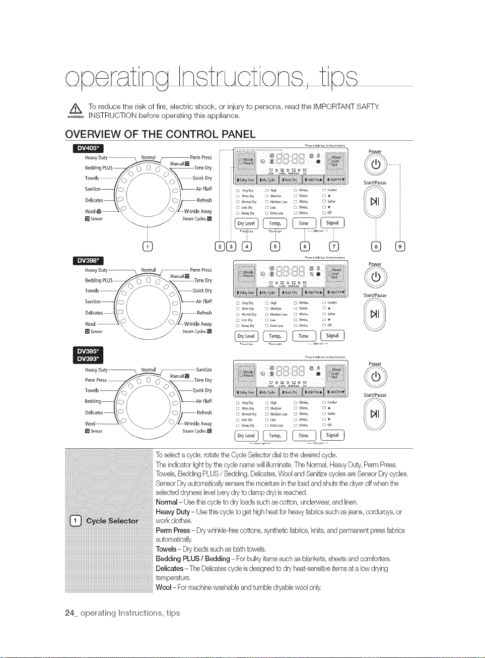
OVERVIEW OF THE CONTROL PANEL
*_,,,,_,4,13,_,.,,,,E,,,_,_,,_i_
Heavy Duty Perm Press
Bedding PLUS___-Time Dry
TT,.... //_-_y _\\ °°':_°,y
1
1 C_ veq _y () }qgl5 ) 60mJ,,. ) louder
I (? Motebq Medium ( 50rain. 5
] E3 Normal r)ry Medium Low {J} 401tlJn, D So_ef
C_ Less Dry () Low ? _0mJtl, )
(30amp Dry C_ Extra ow } 20 nia, L_ off
Power
StarffPause
G
HeawDuty _ Normal _PermPress
Tow°,.... //_y _\\ o_,_Dry
Sanitize , . . _'_ Air Fluff
Wool \_ _ \_/ WrinkleAway
Heavy Duty ?rmal Manual i_ Sanitize
Perm Press Time Dry
Towds _?_ _-_Z_wck Dry
Delicates _ __:..{ }//_ Refresh
®®® ® ® ®
L_ Vm_Dry ( llgl, _ 60rain, [3 tmlder
C3 Mogeg_y Medm c} 50rain F3
C} Normal Dry } Moa[url_ Low :? _llin, _ 5o_('r
L _ Less Dry ( LOW _ 30mJt_, [3 _*
C3 Dam 9 Dry _ Extra ow :120nir_, _3 Off
C} Normal Dry C) p,aedium Low _ #OmJn, [:) soffer
E_ tess DP/ ? Low 30nin [:J)
c:?o_n_D_ _ _xtra_w cs 2o,_ir,. rh dl
* m,_a Haass,. f_rE_r_F,i,_i....
"_mar_ Cat_ _D u i(_t Chit! i)_k _
_ _ _ _,_ _ _ ....
ve_yDry ? H9_ _o,,,il_. [D touder
Mod)rj M,4 u,,, C; 50,,,_n. ,q
_J
®
Power
Star,Pause
Power
StarffPause
_y
24 operating Instructions, tips
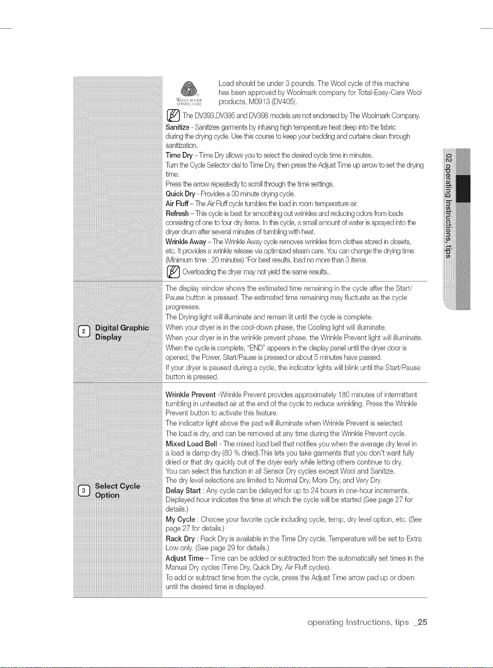
_) Load should be under 3 pounds. The Wool cycle of this machine
_o, M,_ products, M0913 (DV405).
_The and DV398 models endorsed The Woolmark
Sanitize - Sanitizes garments by infusing hightemperature heatdeep intothe fabric
during the drying cycle. Usethis course to keep your bedding and curtains clean through
sanitization.
Time Dry -Time Dryallows you to select thedesired cycle time in minutes.
Turn the Cycle Selector dialto Time Dry,then pressthe AdjustTime up arrow to set the drying
time.
Press the arrow repeatedh!to scroll through the time settings.
Quick Dry - Providesa 30 minute drying cycle.
Air Fluff-The Air Fluffcycle tumbles the load in room temperature air
Refresh - This cycle isbest for smoothing out wrinkles and reducing odors from loads
consisting of one to four dry items. In this cycle, asmall amount ofwater issprayed into the
dryer drum afterseveral minutes of tumbling with heat.
Wrinkle Away - The WrinkleAway cycle removeswrinkles from clothes stored in closets,
etc. Itprovides awrinkle releasevia optimized steam care. You can change the dryingtime.
(Minimum time :20 minutes) *Forbest results, load no more than 3 items.
[_ Overloading dryer may yield same
The display window shows the estimated time remaining in the cycle after the Start/
Pause button is pressed. The estimated time remaining may fluctuate as the cycle
progresses.
The Drying light will illuminate and remain lit until the cycle is complete.
When your dryer is inthe cool-down phase, the Cooling light will illuminate.
When your dryer is inthe wrinkle prevent phase, the Wrinkle Prevent light will illuminate.
When the cycle is complete, "END" appears in the display panel until the dryer door is
opened, the Power, Start/Pause is pressed orabout 5 minutes have passed.
If your dryer ispaused during a cycle, the indicator lights will blink until the Start/Pause
button is pressed.
has been approved by Woolmark company for Total-Easy-Care Wool
DV393,DV395 are
the not the results..
not
by Company.
Wrinkle Prevent -Wrinkle Prevent provides approximately 180 minutes of intermittent
tumbling in unheated air at the end of the cycle to reduce wrinkling. Press the Wrinkle
Prevent button to activate this feature.
The indicator light above the pad will illuminate when Wrinkle Prevent is selected.
The load is dry, and can be removed at any time during the Wrinkle Prevent cycle.
Mixed Load Bell - The mixed load bell that notifies you when the average dry level in
a load isdamp dry (80 % dried).This lets you take garments that you don't want fully
dried or that dry quickly out of the dryer early while letting others continue to dry.
You can select this function in all Sensor Dry cycles except Wool and Sanitize.
The dry level selections are limited to Normal Dry, More Dry, and Very Dry.
Delay Start : Any cycle can be delayed for up to 24 hours in one-hour increments.
Displayed hour indicates the time at which tile cycle will be started (See page 27 for
datails)
My Cycle: Choose your favorite cycle including cycle, temp, dry level option, etc. (See
page 27 for details.)
Rack Dry : Rack Dry is available in the Time Dry cycle. Temperature will be set to Extra
Low only. (See page 29 for details.)
Adjust Time - Time can be added or subtracted from the automatically set times in the
Manua Drycydes Dry,OuickDry,huffcydes)
To add or subtract time from tile cycle, press tile Adjust Time arrow pad up or down
until tile desired time is displayed.
operating Instructions, tips 25
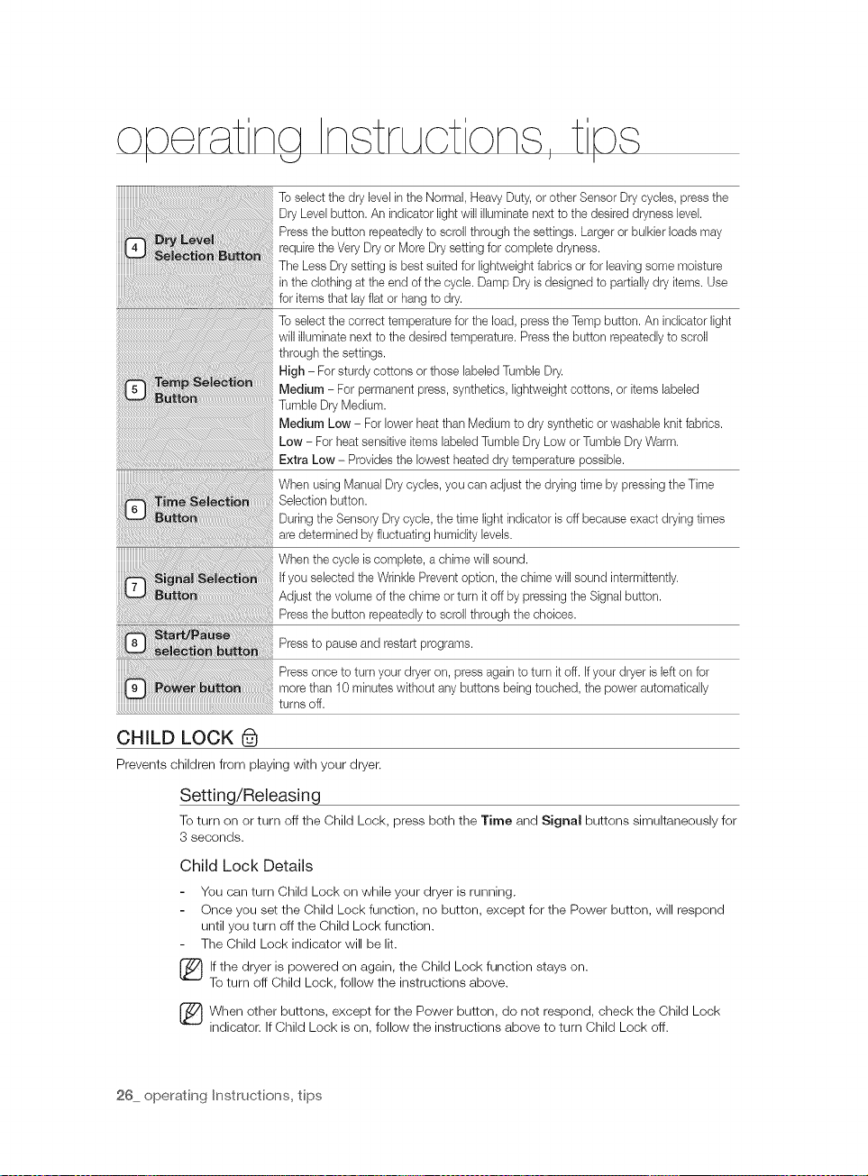
To select the dry level inthe Normal, Heavy Duty, or other Sensor Drycycles, press the
Dry Level button. An indicator light will illuminate next to the desired dryness level.
Press the button repeatedly to scroll through the settings. Larger or bulkier loads may
require the Very Dry or More Dry setting for complete dryness.
The Less Dry setting is best suited for lightweight fabrics or for leaving some moisture
in the clothing at the end of the cycle. Damp Dry is designed to partially dry items. Use
for items that lay flat or hang to dry.
To select the correct temperature for the load, press the Temp button. An indicator light
will illuminate next to the desired temperature. Press the button repeatedly to scroll
through the settings.
High - For sturdy cottons or those labeled Tumble Dry.
Medium - For permanent press, synthetics, lightweight cottons, or items labeled
Tumble Dry Medium.
Medium Low - For lower heat than Medium to dry synthetic or washable knit fabrics.
Low - For heat sensitive items labeled Tumble Dry Low or Tumble Dry Warm.
Extra Low - Provides the lowest heated dry temperature possible.
When using Manual Dry cycles, you can adjust the drying time by pressing the Time
Selection button.
During the Sensory Dry cycle, the time light indicator is off because exact drying times
are determined by fluctuating humidity levels.
When the cycle is complete, a chime will sound.
If you selected the Wrinkle Prevent option, the chime will sound intermittently.
Adjust the volume of the chime or turn it off by pressing the Signal button.
Press the button repeatedly to scroll through the choices.
Press to pause and restart programs.
Press once to turn your dryer on, press again to turn it off. If your dryer is left on for
more than 10 minutes without any buttons being touched, the power automatically
turns off.
CHILD LOCK (_
Prevents children from playing with your dryer.
Setting/Releasing
To turn on or turn off the Child Lock, press both the Time and Signal buttons simultaneously for
3 seconds.
Child Lock Details
You can turn Child Lock on while your dryer is running.
Once you set the Child Lock function, no button, except for the Power button, will respond
until you turn off the Child Lock function.
The Child Lock indicator will be lit.
lf the dryer is powered on again, the Child Lock function stays on.
To turn off Child Lock, follow the instructions above.
[_ hen other buttons, except for the Power button, do not respond, check the Child Lock
indicator. If Child Lock is on, follow the instructions above to turn Child Lock off.
26 operating Instructions, tips
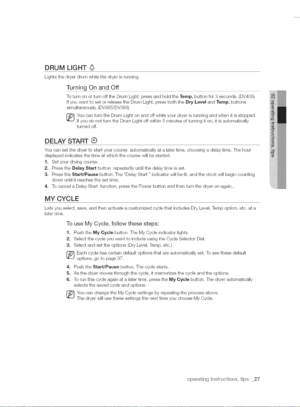
DRUM LIGHT ..0,.
Lights the dryer drum while the dryer is running.
Turning On and Off
To turn on or turn off the Drum Light, press and hold the Temp. button for 3 seconds. (DV405)
If you want to set or release the Drum Light, press both the Dry Level and Temp. buttons
simultaneously. (DV395/DV393)
You can turn the Drum Light on and off while your dryer is running and when it is stopped.
If you do not turn the Drum Light off within 5 minutes of turning it on, it is automatically
turned off.
DELAY START Q
You can set the dryer to start your course automatically at a later time, choosing a delay time. The hour
displayed indicates the time at which the course will be started.
1. Set your drying course.
2. Press the Delay Start button repeatedly until the delay time is set.
3. Press the Start/Pause button. The "Delay Start " indicator will be lit, and the clock will begin counting
down until it reaches the set time.
4. To cancel a Delay Start function, press the Power button and then turn the dryer on again..
MY CYCLE
Lets you select, save, and then activate a customized cycle that includes Dry Level, Temp option, etc. at a
later time.
To use My Cycle, follow these steps:
1. Push the My Cycle button. The My Cycle indicator lights.
2. Select the cycle you want to include using the Cycle Selector Dial.
3. Select and set the options (Dry Level, Temp, etc.)
Each cycle has certain default options that are automatically set. To see these default
options, go to page 37.
4. Push the Start/Pause button. The cycle starts.
5. As the dryer moves through the cycle, it memorizes the cycle and the options.
6. To run this cycle again at a later time, press the My Cycle button. The dryer automatically
selects the saved cycle and options.
You can change the My Cycle settings by repeating the process above.
The dryer will use these settings the next time you choose My Cycle.
operating Instructions, tips 27
 Loading...