


5-1-1 Before Making Adjustments
5-1-1 (a) ORIENTATION
When servicing, always face the monitor to the
east.
5-1-1 (b) MAGNETIC FIELDS
Whenever possible, use magnetic field isolation
equipment such as a Helmholtz field to surround
the monitor. If a Helmholtz field is not available,
frequently degauss the unit under test.
Caution: Other electrical equipment may cause
external magnetic fields which may
interfere with monitor performance.
Use an external degaussing coil to limit magnetic
build up on the monitor. If an external degaussing
coil is not available, use the internal degaussing
circuit. However, do not use the internal
degaussing circuit more than once per 30 minutes.
5-1-1 (c) WARM-UP TIME
The monitor must be on for 30 minutes before
starting alignment procedures. Warm-up time is
especially critical in Color Temperature and White
Balance adjustments.
5-1-1 (d) SIGNAL
Analog, 0.7 Vp-p positive at 75 ohm, internal
termination
Sync: Separate
(TTL level negative/positive)
5-1-1 (e) SCANNING FREQUENCY
Horizontal: 30 kHz to 55 kHz (automatic) 14Ó
30 kHz to 61 kHz (automatic) 15Ó
Vertical: 50 Hz to 120 Hz (automatic)
Unless otherwise specified, adjust at the 800 x 600
mode (H : 53.7 kHz, V: 85 Hz) -14Ó/15Ó signals.
Refer to Table on page 2-3.
5-1-1 (f) +B 13 V LINE CHECK
No beam
Contrast: Maximum
Brightness: Maximum
Check the DC 13 V ± 0.2 V at Cathode of D616
Point and GND.
5-1-1 (g) HIGH VOLTAGE CHECK
No beam
Contrast: Maximum
Brightness: Maximum
Check the high voltage to 24.5 ± 0.5 kV - 14Ó,
25 ± 0.5 kV - 15Ó at anode and GND.
5-1-1 (h) CENTER RASTER
Adjust VR501 so that the back raster comes to the
center when you apply a signal of
60 kHz/75 Hz - 15Ó .
5-1-1 (i) BRIGHTNESS AND CONTRAST
Unless otherwise specified, adjust brightness and
contrast buttons:
Brightness: Maximum
(press Å button until the LED is blink)
Contrast: Maximum
(press Å button until the LED is blink)
5-1-2 Required Equipment
The following equipment may be necessary for
adjustment procedures:
5-1-2 (a) DISPLAY CONTROL ADJUSTMENT
1. Non-metallic (Ð) screwdriver: 1.5 mm
Non-metallic (Ð) screwdriver: 3 mm
2. Philips (+) screwdriver: 1.5 mm
3. Non-metallic hexkey: 2.5 mm
4. Digital Multimeter (DMM), or
Digital Voltmeter (DVM)
DP14L*/DP15L* 5-1
5 Alignment and Adjustments
This section of the service manual explains how to make permanent adjustments to the monitor. Directions
are given for adjustments using the monitor Interface Board Ver. 2.0 and software (Softjig).
5-1 Adjustment Conditions
Caution: Changes made without the SoftJig are saved only to the user mode settings. As such, the
settings are not permanently stored and may be inadvertently deleted by the user.
5. Signal generator, or
Computer with a video board that uses the
ET-4000 chipset (strongly recommended if
using Samsung DM 200 software) and that
displays: 800 x 600 @ 85 Hz, or 800 x 600
@ 75 Hz (minimum).
6. Personal computer
7. Required software: Softjig.exe from Samsung,
Samsung DM200, or DisplayMate for
Windows from Sonera Technologies
8. Interface Board Ver. 2.0 Code No.
BH81-90001K
9. Parallel communications cable (25-pin to
25-pin); Code No. BH81-90001H
10. Signal cable (15-pin to 15-pin cable with
additional 3-pin connector); Code No.
BH81-90001J
11. 5 V DC adapter, not supplied
Note: SoftJig Assembly (includes items 8, 9 and 10
Code No. BH81-90001L
5-1-2 (b) COLOR ADJUSTMENTS
1. All equipment listed in 5-1-2 (a), above
2. Color analyzer, or any luminance
measurement equipment
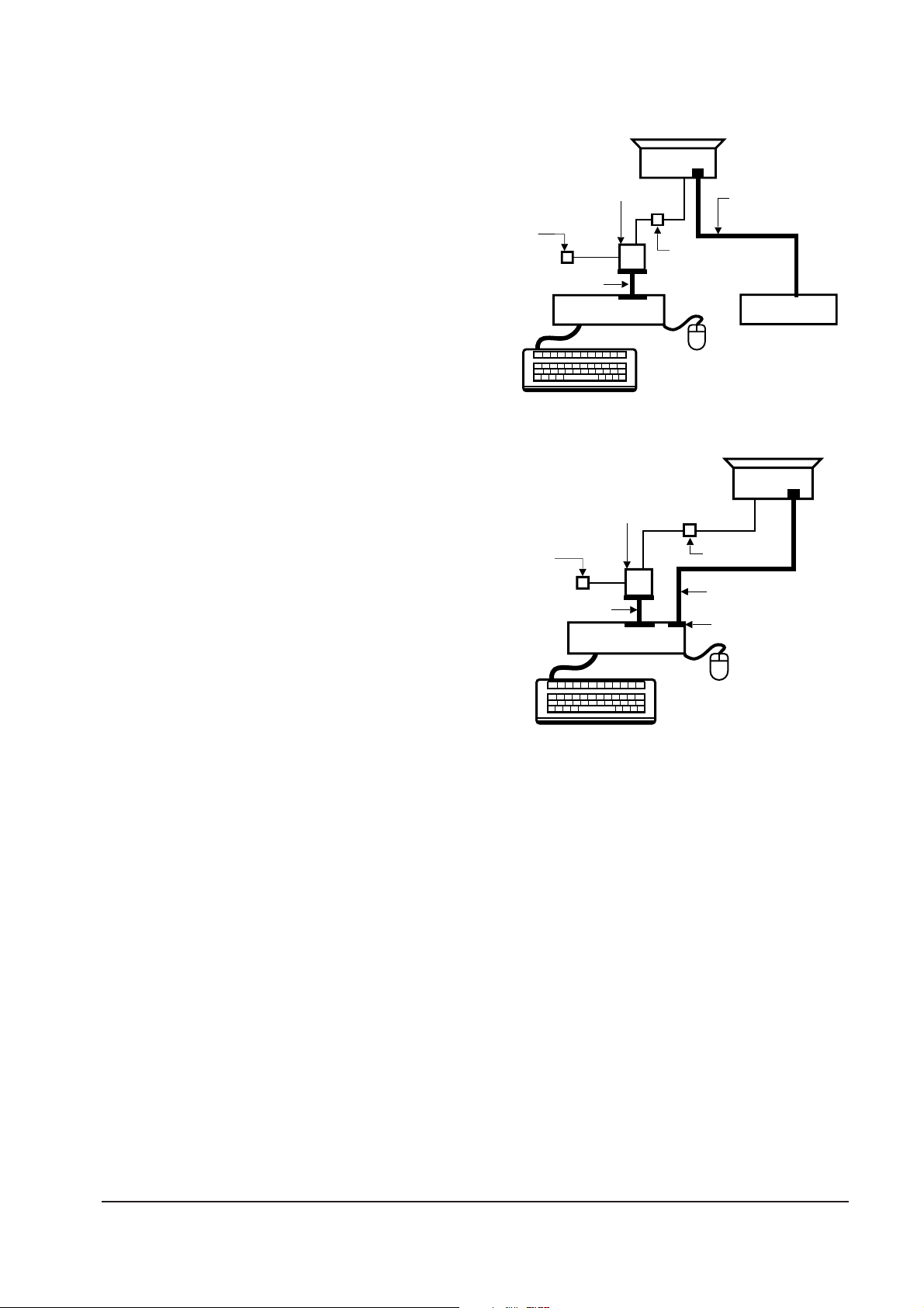
5-1-3 Connecting the SoftJig
Connect the monitor to the signal generator and/
or PC as illustrated in Figures 5-1 and 5-2.
Note: The signal cable connector which includes
the 3-wire cable must connect to the
monitor. If you use Setup 2 (PC only, no
signal generator) you can only make
adjustments to the signal timing available
on that computer system. To make
corrections to all factory timings requires
the use of an additional signal generator.
5-1-4 After Making Adjustments
After finishing all adjustments, test the monitor in
all directions. If, for example, the monitor does not
meet adjustment specifications when facing north,
reposition the monitor to face east and readjust.
This time, try for an adjustment closer to the ideal
setting within the tolerance range. Test the unit
again in all directions. If the monitor again fails to
meet specifications in every direction, contact
your Regional After Service Center for possible
CRT replacement.
5 Alignment and Adjustments
5-2 DP14L*/DP15L*
MONITOR
INTERFACE
BOARD VER. 2.0
PC
SIGNAL
GENERATOR
7 PIN MINI DIN
CONNECTOR
SIGNAL CABLE
5V DC
ADAPTOR
PARALLEL CABLE
Figure 5-1. Setup 1, With Signal Generator
MONITOR
INTERFACE
BOARD VER. 2.0
PC
7 PIN MINI DIN
CONNECTOR
SIGNAL CABLE
PARALLEL CABLE
D-SUB
CONNECTOR
5V DC
ADAPTOR
Figure 5-2. Setup 2, Without Signal Generator
 Loading...