

Samsung DP15LS Troubleshooting

DP14L*/DP15L* 6-1
6 Troubleshooting
6-1 General Troubleshooting
Notes: 1. If a picture does not appear, fully rotate the brightness and contrast controls clockwise and reinspect.
2. Check the following circuits.
• No raster appears: Power circuit, Horizontal output circuit, H/V control circuit, and H/V output circuit.
• High voltage develops but no raster appears: Video output circuits.
• High voltage does not develop: Horizontal output circuits.
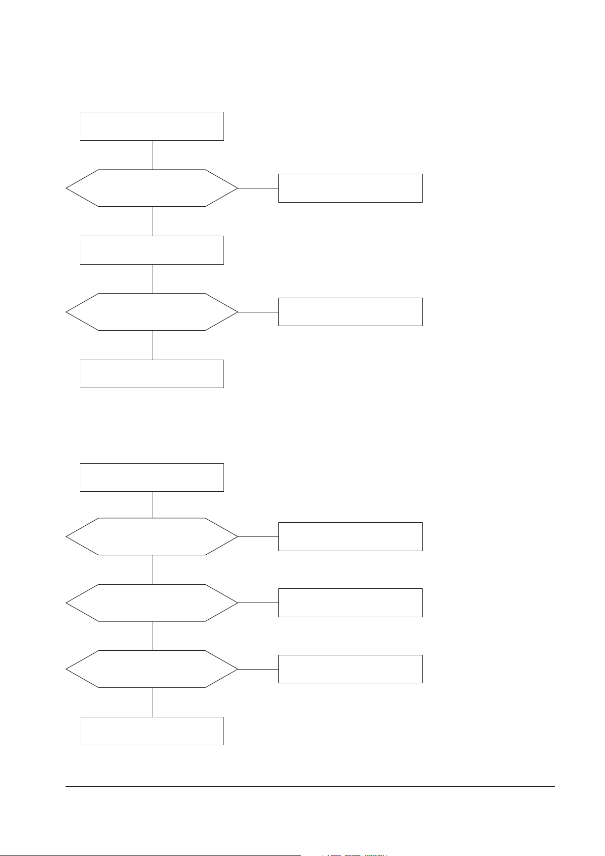
6-1-1 No Picture
Check signal cable connection, H/V Sync input.
Check Timing mode (14”: 30~55kHz, 15”: 30~61kHz).
Check Cont,
Bright
key (all Max) and Screen VR (G2).
Check key components of secondary part. :
D406, D407, D408, D515, Q402, Q410, Q504, Rectifier
diodes (D608 ~ D612), IC101 (Vcc~GND)
Check key components of primary part. :
D601 ~ D607, FH601, IC601, TH602
Check SW601 (Power key)
Refer to 6-2-16 No Video.
Refer to 6-2-1 No Power.
Refer to 6-2-3 No Raster and 6-2-12 High Voltage Failure.
Refer to 6-2-17 Micom Failure.
Refer to 6-2-13 I2C Failure.

6 Troubleshooting
6-2 DP14L*/DP15L*
6-1-2 Shut Down
Check X-ray protection circuit. :
D502, D503, R510
Check key components of secondary part. :
D406, D407, D408, D515, IC101 (Vcc ~ GND)
Q402, Q504, Rectifier diodes
Check and replace IC601.
Refer to 6-2-1 No Power.
Refer to 6-2-3 No Raster and 6-2-12 High Voltage Failure.
Refer to 6-2-17 Micom Failure.
Refer to 6-2-13 I2C Failure.

6 Troubleshooting
DP14L*/DP15L* 6-3
6-1-3 No Video or Missing Colors
Are 0.7Vp-p video input on
CN202_2 R, G, B?
Check signal cable and generator.
Yes
No
Are proper waveform on
SK103’s R, G, B cathode?
Refer to 6-2-16 No Video.
Yes
No
Is G2 and heater voltage OK?
Check and replace SK103 and
some parts around it.
Yes
No
Change CRT and replace it.
Check white balance adjustment.
WAVEFORMS
22
19
19
46.4 V (SK103, G)
CH1 P-P = 46.4 V CH1 RMS = 38.16 V
22
1.016 V (CN202_2, #2,4,6)
CH1 P-P = 1.016 V CH1 RMS = 174.4 mV
WAVEFORMS
17
35.2 V (SK103, G1)
CH1 P-P = 35.2 V CH1 RMS = 80.84 V
25
4.96 V (IC201, #30)
CH1 P-P = 4.96 V CH1 RMS = 350 mV
Check signal cable connection, H/V Sync input.
Check Timing mode (14”: 30~55kHz, 15”: 30~61kHz).
Check Cont, Brit key (all Max) and Screen VR (G2).
6-1-4 Visible Retrace
Is G2 voltage (Screen VR) OK?
Adjust Screen VR to 0.4~0.6F/L (back
raster) at cont, bright all max.
Yes
No
Is V_sync input on Q301 base?
Check V_sync input line.
Yes
No
Is proper G1 pulse on SK103’s
G1 pin?
Check C306, C506, D504
Q301, Q501 and around parts.
Yes
No
Check and replace CRT.
25
17

6 Troubleshooting
6-4 DP14L*/DP15L*
6-1-5 Unsynchronized image
Are H/V sync input on IC201’s
Pins 30 and 31?
Check the connection of signal cable.
Refer to 6-2-12 High Voltage Failure.
Yes
Check H/V sync input line.
No
6-1-6 Misconvergence
Spec in?
(Center : 0.3 mm, Cornor : 0.4 mm)
Readjust Misconvergence.
Done
Yes
Change CRT and readjust
Miconvergence and color.
No
Refer to 6-2-17 Micom
Failure.
No
Are H/V sync input on IC401’s
Pins 1 and 2?
Yes
Check and replace IC401.
Yes
Check H/V sync input line.
No
Check and replace IC201.
No
WAVEFORMS
24
26
25
27
24
5.28 V (IC201, #31)
CH1 P-P = 5.28 V CH1 RMS = 1.218 V
25
4.96 V (IC201, #30)
CH1 P-P = 4.96 V CH1 RMS = 350 mV
26
5.48 V (IC401, #1)
CH1 P-P = 5.48 V CH1 RMS = 1.362 V
27
4.48 V (IC401, #2)
CH1 P-P = 4.48 V CH1 RMS = 284 mV
6 Troubleshooting
DP14L*/DP15L* 6-5
6-1-7 Poor Focus
Improved Focus?
Aging monitor and check focus
change for 1~2 hours.
Check Focus lead from FBT to
CRT Socket.
Adjust Focus VR.
No
Yes
Are the CRT Socket and
connection OK?
Replace and connect it.
Check and replace CRT.
Yes
Yes
No
6-1-8 Purity Failure
Degaussing
Is purity OK?
Done
No
Yes
IS degaussing circuit OK?
Refer to 6-2-20 Degaussing Failure.
Yes
No
Check if there is strong
electric or magnetic fields near
user’s circumstance?
Recommend free electric or
magnetic field.
No
Yes
Change CRT and readjust
misconvergence and color.

6 Troubleshooting
6-6 DP14L*/DP15L*
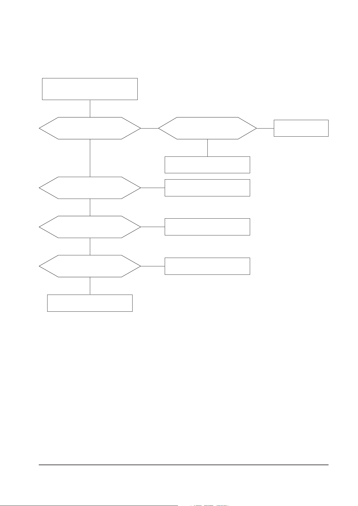
6-2 Detail Repair Section
Notes: 1. If a picture does not appear
check first • if AC power cord is plugged or not,
• if signal cable is connected or not,
• if signal generator (PC) is operated well or not (DPMS mode)
• if the Timing mode is out of spec or not (14”: 30~55 kHz, 15”: 30~61 kHz)
Does recitfied voltages of
secondary part appear on C620,
C622, C623, C624, C630?
Refer to 6-2-3 No Raster and
6-2-12 High Voltage Failure.
Check and replace D406, D407, D408,
IC101, Q402, Q410, Q504
Yes
Are D608 ~ D612 OK?
Replace it.
Check and Replace
IC601, T601.
Check and replace D602, D603, D607,
IC601, T602.
No
No
Does rectified voltage
(1.4 x AC input) of primary part
appear on C607?
Check and replace
D601~D607, FH601, TH602.
Yes
Yes
No
Is IC601’s Pin 1 OK?
No
Yes
Yes
Is IC601’s Pin 5 OK?
NoYes
Does rectified voltage
(1.4 x AC input) of primary
part appear on C617?
No
6-2-1 No Power
Check and replace IC601, T601.
Check and replace T601 and
around parts.
WAVEFORMS
1
2
1
410 V (IC601, #1)
CH1 P-P = 410 V CH1 RMS = 332.8 V
2
8.40 V (IC601, #5)
CH1 P-P = 8.40 V CH1 RMS = 4.680 V
Desolder IC601’s Pin 1.
No
6 Troubleshooting
DP14L*/DP15L* 6-7
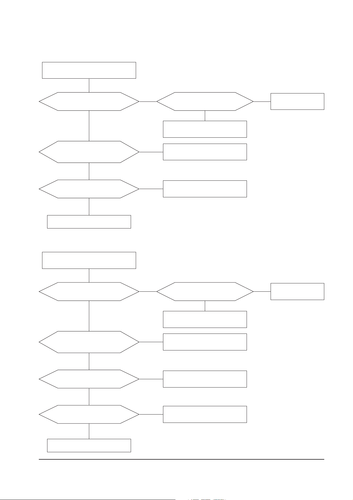
Is LED blinking? (1 sec toggle)
Check and replace
OP201.
Make sure that there is No H/V sync
from signal generator. (Signal cable
should be connected)
Yes
Are there 0V on IC201’s Pin 5 (sus)
and 0V on IC201’s Pin 6 (off)?
Check and replace IC201.
Check and replace IC201.
No
Is OP201 OK?
Yes
No
No
Yes
+6.3 V line Off?
Check and replace Q603, Q604.
No
+12 V Off?
Check and replace Q605 ~ Q608.
No
Yes
Yes
Done
6-2-2 DPMS Failure
6-2-2 (a) Off Mode (No H/V sync)
6 Troubleshooting
6-8 DP14L*/DP15L*
6-2-2 (b) Suspend Mode (H sync: OK, V sync: No)
Is LED blinking? (0.5 sec toggle)
Check and replace
OP201.
Make sure that H sync is OK and V sync is
not. (Signal cable should be connected)
Yes
Are there 0V on IC201’s Pin 5 (sus)
and 5V on IC201’s Pin 6 (off)?
Check and replace IC201.
Check and replace IC201.
No
Is OP201 OK?
Yes
No
No
Yes
+12 V Off?
Check and replace Q605 ~ Q608.
No
Yes
Done
6-2-2 (c) Stand-by Mode (H sync: No, V sync: OK)
Is LED blinking? (0.5 sec toggle)
Check and replace
OP201.
Make sure that H sync is not and V sync is
OK. (Signal cable should be connected)
Yes
Are there 5V on IC201’s Pin 5 (sus)
and 0V on IC201’s Pin 6 (off)?
Check and replace IC201.
Check and replace IC201.
No
Is OP201 OK?
Yes
No
No
Yes
Is high voltage On?
Refer to 6-2-3 No Raster and
6-2-12 High Voltage Failure.
No
Yes
Video Mute?
Refer to 6-2-16 No Video and
6-2-13 I2C Failure.
No
Yes
Done
 Loading...