

Page 1

2
CONTENTS
ⅠⅠ
.. SSPPEECCIIFFIICCAATTIIOONN
1. SPECIFICATION ……………………………………………………………………………………………………… 4
2. SYSTEM REQUIRMENT ……………………………………………………………………………………………… 5
3. LCD MONITOR INDICATOR ………………………………………………………………………………………… 6
4. CONNECTION DIAGRAM …………………………………………………………………………………………… 8
5. IDENTIFICATION OF FEATURES ………………………………………………………………………………… 9
ⅡⅡ
.. IINNSSTTAALLLLAATTIIOONN && FFAAQQ
……………………………………………………………………………………… 11
ⅢⅢ
.. EEXXPPLLOODDEEDD VVIIEEWW AANNDD PPAARRTTSS LLIISSTT
1. MAIN ASSEMBLY…………………………………………………………………………………………………… 40
2. BODY ASSEMBLY ………………………………………………………………………………………………… 42
3. BARREL ASSEMBLY ……………………………………………………………………………………………… 44
4. FRONT COVER ASSEMBLY ……………………………………………………………………………………… 46
5. BACK COVER ASSEMBLY ………………………………………………………………………………………… 48
6. BARRIER AND FINDER ASSEMBLY ……………………………………………………………………………… 50
7. PACKING ITEMS …………………………………………………………………………………………………… 52
8. INITIAL PARTS LIST ……………………………………………………………………………………………… 54
ⅣⅣ
.. AADDJJSSUUTTMMEENNTT
1. REPLACEMENT PARTS AND ADJUSTMENT ITEMS ……………………………………………………………56
2. ADJUSTMENT TOOLS ……………………………………………………………………………………………… 56
3. ADJUSTMENT FLOW ……………………………………………………………………………………………… 57
4. ADJUSTMENT ITEMS ……………………………………………………………………………………………… 57
ⅤⅤ
.. PPAATTTTEERRNN DDIIAAGGRRAAMMSS
1. PARTS ARRANGEMENT FOR EACH PCB ASS’Y
1) MAIN PCB ASSEMBLY ………………………………………………………………………………………… 58
2) POWER PCB ASSEMBLY ……………………………………………………………………………………… 60
3) LCD PCB ASSEMBLY ………………………………………………………………………………………… 62
4) JACK PCB ASSEMBLY ………………………………………………………………………………………… 64
2. BLOCK DIAGRAM ……………………………………………………………………………………………………65
Page 2

3
ⅥⅥ
.. TTRROOUUBBLLEESSHHOOOOTTIINNGG
1. CHECK LIST FOR REPAIRING …………………………………………………………………………………… 66
2. VERSION CHECK…………………………………………………………………………………………………… 67
3. FIRMWARE UPGRADE……………………………………………………………………………………………… 68
4. PARTS EXPLANATION OF EACH PCB
1) MAIN PCB ASSEMBLY(TOP) …………………………………………………………………………………70
2) MAIN PCB ASSEMBLY(BOTTOM) ……………………………………………………………………………71
3) POWER PCB ASSEMBLY(TOP)…………………………………………………………………………………72
4) POWER PCB ASSEMBLY(BOTTOM)……………………………………………………………………………73
5) LCD PCB ASSEMBLY(TOP) ……………………………………………………………………………………74
6) LCD PCB ASSEMBLY(BOTTOM) ………………………………………………………………………………75
7) JACK PCB ASSEMBLY(TOP) ……………………………………………………………………………………76
8) JACK PCB ASSEMBLY(BOTTOM) ………………………………………………………………………………76
5. MODIFICATION……………………………………………………………………………………………………… 77
6. PRINCIPAL TROUBLESHOOTING
1) DOES NOT POWER ON ……………………………………………………………………………………… 78
2) FLASHING DEFECT …………………………………………………………………………………………… 86
3) CHARGING DEFECT …………………………………………………………………………………………… 87
4) IF IMAGES CAM BE SEEN ON LCD PANEL BUT BACK LIGHT IS NOT TURNED ON ……………… 88
5) IN CASE LCD BECOMES ALL WHITE ……………………………………………………………………… 89
6) AUDIO PART …………………………………………………………………………………………………… 90
7) ZOOM DEFECT. ………………………………………………………………………………………………… 91
7. DISASSEMBLE THE CAMERA …………………………………………………………………………………… 92
8. DISASSEMBLE THE BARREL ……………………………………………………………………………………… 97
9. ASSEMBLE THE BARREL ………………………………………………………………………………………… 99
Page 3
4
Ⅰ
. SPECIFICATION
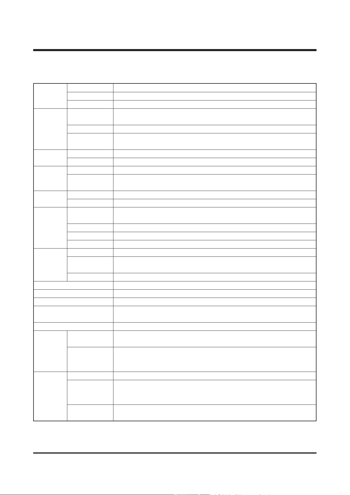
11.. CCaammeerraa SSppeecciiffiiccaattiioonn
Type 1/2.7″CCD
Effective Pixels Approx. 3.2 Mega pixels
Total Pixels Approx. 3.3 Mega pixels
SHD Lens f = 5.8 ~ 17.4mm
(35mm film equivalent : 38 ~ 114mm)
Lens F No. F2.8 ~ F4.8
Still Image mode : 1.0X ~ 3.0X
Play mode : 1.0X ~ 5.0X (depends on image size)
Optical Viewfinder Real image optical viewfinder
LCD Monitor 1.5″color TFT LCD
Type TTL auto focus
Focusing Normal : 80cm ~ infinity
Macro : Wide- 5cm ~ 80cm, Tele- 50cm ~ 80cm
Type Mechanical and Electronic shutter
Speed Normal : 2 ~ 1/2,000 sec.
Night :
15 ~ 1/2,000 sec.
Program AE
Metering : Multi, Spot
Exposure Compensation ±2.0EV (0.5EV steps)
ISO Auto, 100, 200, 400
Manual Exposure Electronic shutter : 1/8 ~ 16 sec. (1EV steps)
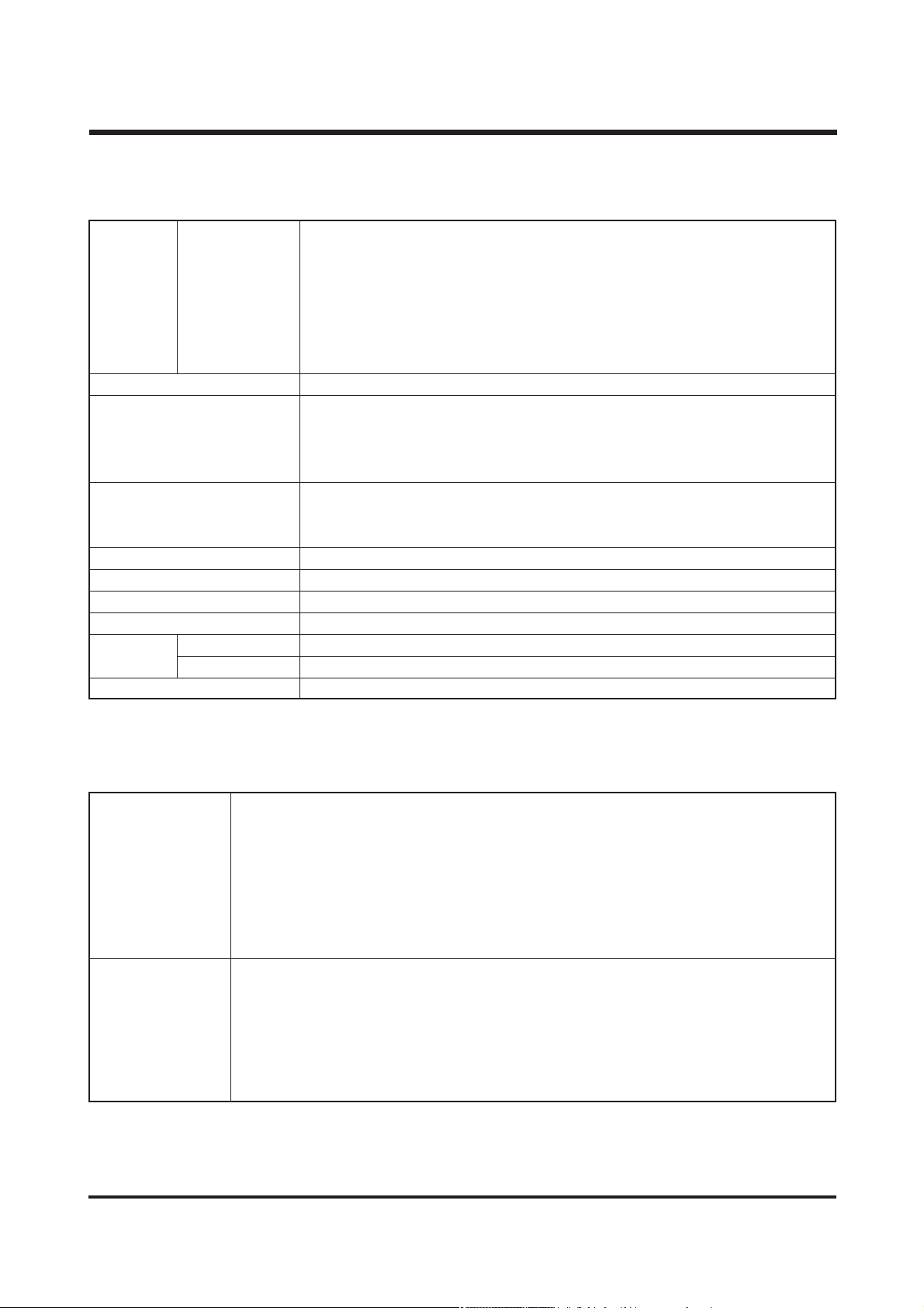
Mode Auto/ Red-eye reduction/ Fill-in flash/ Slow sync/ Flash off
Normal - Wide : 0.8 ~ 3.0m, Tele : 0.8 ~ 2.0m
Macro - Wide : 0.2 ~ 0.8m, Tele : 0.5 ~ 0.8m
Recharging Time Approx. 7 sec.
Sharpness Soft/ Normal/ Vivid
Effect Normal/ B&W/ Sunset/ Sepia/ RGB
White Balance Auto/ Daylight/ Cloudy/ Fluorescent/ Tungsten/ User set
Voice recording
Voice memo (Max. 10 sec. : Still Image)
Imprint Off/ Date/ Date&Time (user selectable)
Modes :
Auto, Night
, Myset
Self-timer : 2 sec, 10 sec.
Shooting With Voice
Movie Clip Size : 320x240, 160x128 (user selectable)
(15, 24 frames/sec, Recording time : memory capacity dependent)
Media Memory Stick Duo (up to 256MB guaranteed)
Still Image : JPEG(DCF), EXIF 2.2, DPOF
File Format Movie Clip : MOV(MPEG4)
Voice : WAV(G.711)
Image Size 2048: 2048x1536, 2048P: 2048x1360, 1600: 1600x1200
(pixels) 1024: 1024x768, 640: 640x480
Image
Sensor
Viewfinder
Shutter
Storage
Voice Recording
Flash
Focal Length
Digital Zoom
Range
Control
Range(AUTO)
Still Image
Page 4
5
ⅠⅠ.. SS PP EE CC IIFFII CC AA TTII OO NN
22.. SSyysstteemm RReeqquuiirreemmeennttss
PC with processor better than MMX Pentium 233MHz (XP : Pentium II 300MHz)
Windows 98/98SE/2000/ME/XP
Minimum 32MB RAM (XP : 128MB)
For Windows
140MB of available hard-disk space
USB port
CD-ROM drive
800x600 pixels, 16-bit color display compatible monitor
(24-bit color display recommended)
PowerMac G3 or later
MacOS 9.x ~ 10.2
Minimum 64MB RAM
For Macintosh
110MB of available hard-disk space
USB port
CD-ROM drive
QuickTime 4.0 or later (for Movie Clip)
2048 :Super fine 17, Fine 33, Normal 50
2048P :Super fine 27, Fine 54, Normal 82
1600 :Super fine 27, Fine 54, Normal 82
1024 :Super fine 63, Fine 132, Normal 198
640 :Super fine 169, Fine 336, Normal 501
* These figures are measured under Samsung’s standard conditions
and may vary depending on shooting conditions and camera settings.
Image Play Single image/ Thumbnails/ Slide show/ Movie clip
Digital output connector : USB
Audio : Mono
Video output : NTSC, PAL (user selectable)
DC power input connector : 3.3V
Included : Rechargeable Lithium-ion Battery (1000mAh, 3.7V)
Power Source Optional: Duracell CP-1 battery, AC adapter (DC 3.3V, 2A)
* Included battery may vary depending on sales region.
Dimensions (WxHxD) 102 x 53.8 x 31.6mm
Weight Approx. 119g (without batteries and card)
Operating Temperature 0 ~ 40 ℃
Operating Humidity 5 ~ 85 %
Camera Driver Storage Driver (Windows98/98SE/2000/ME/XP, Mac OS 9.0~10.2)
Application MGI PhotoSuite, Digimax Viewer 2.0
Special Function Avatar Start Screen, MPEG-4 Movie clip, 7 Colors Function lamp, RGB Color Effect
Software
Interface
Capacity
(32MB)
Page 5
6
ⅠⅠ.. SS PP EE CC IIFFII CC AA TT II OO NN
33.. LLCCDD mmoonniittoorr iinnddiiccaattoorr
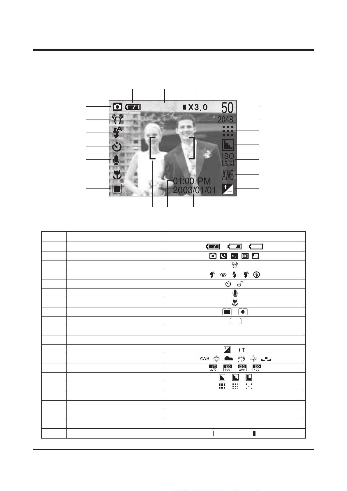
■ Recording mode
No. Description Icons
1 Battery
2 Recording mode
3 Camera shake warning
4 Flash
5 Self-timer
6 Voice memo
7 Macro
8 Metering
9 Auto focus frame
10 Time 01:00 PM
11 Date 2003/01/01
12 Exposure compensation
13 White Balance
14 ISO
15 Sharpness
16 Image quality
17 Image size 2048, 2048P, 1600, 1024, 640
Number of available shots remaining
25
Remaining time( Movie clip/ Voice recording)
00:05:00
19 Digital Zoom rate X3.0
20 Optical Zoom
[ Image & Full Status ]
②
⒃
③
④
⑤
⑥
⑮
⑭
⑬
⑫
⑪
⑩
⑦
⑧
⑨
⒔
⒕
①
⒗
⒖
18
Page 6
7
ⅠⅠ.. SS PP EE CC IIFFII CC AA TT II OO NN
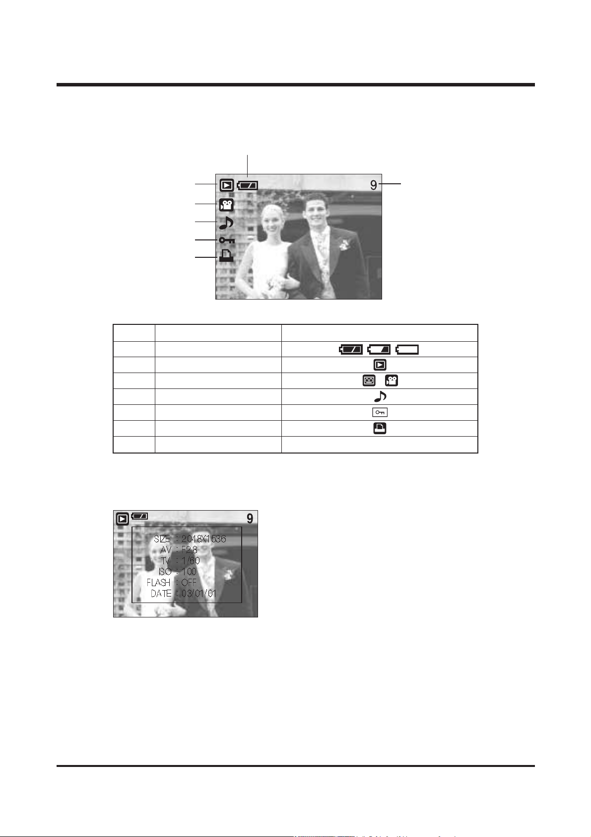
■ Play mode
No. Description Icons
1 Battery
2 Play mode
3 File type
4 Voice memo
5 Protect indicator
6 DPOF indicator
7 Stored image number 9
②
SIZE : 2048x1536 Image size
AV : F2.8 Aperture value
TV : 1/60 Shutter speed
ISO : 100 ISO sensitivity
FLASH : OFF Whether or not the
flash is used.
DATE : 03/01/01 Recording date
⑥
③
④
⑤
⑦
①
Page 7
8
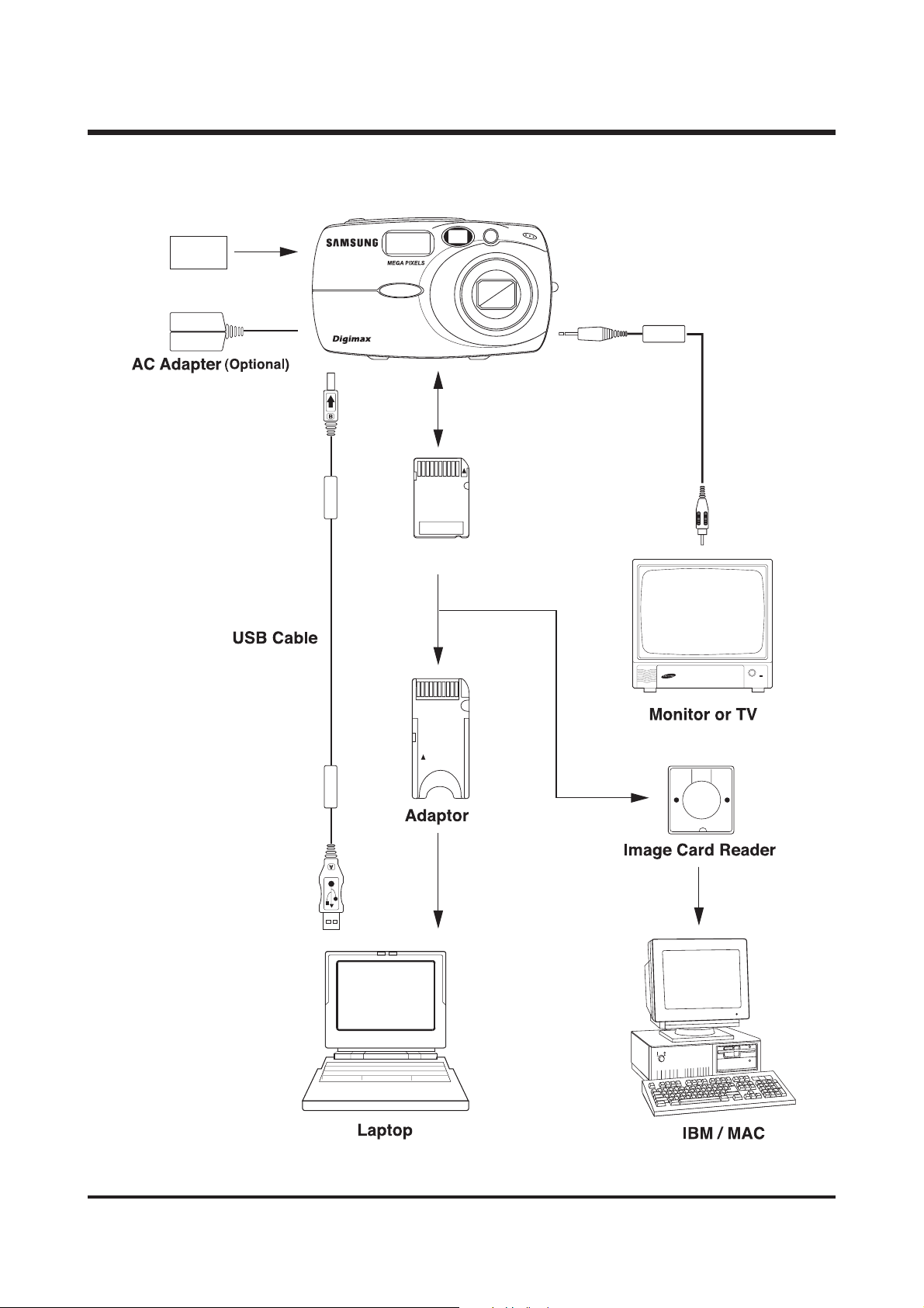
44.. CCoonnnneeccttiioo nn ddiiaaggrraamm
ⅠⅠ.. SS PP EE CC IIFFII CC AA TT II OO NN
U-CA 3
Lithium-Ion SLB-1037
3.2
S
H
G
D
N
U
L
S
M
A
S
Z
O
m
O
4
M
.
7
5
1
-
.
8
U-CA 3
Memory Stick Duo
E
N
S
m
Page 8
9
ⅠⅠ.. SS PP EE CC IIFFII CC AA TT II OO NN
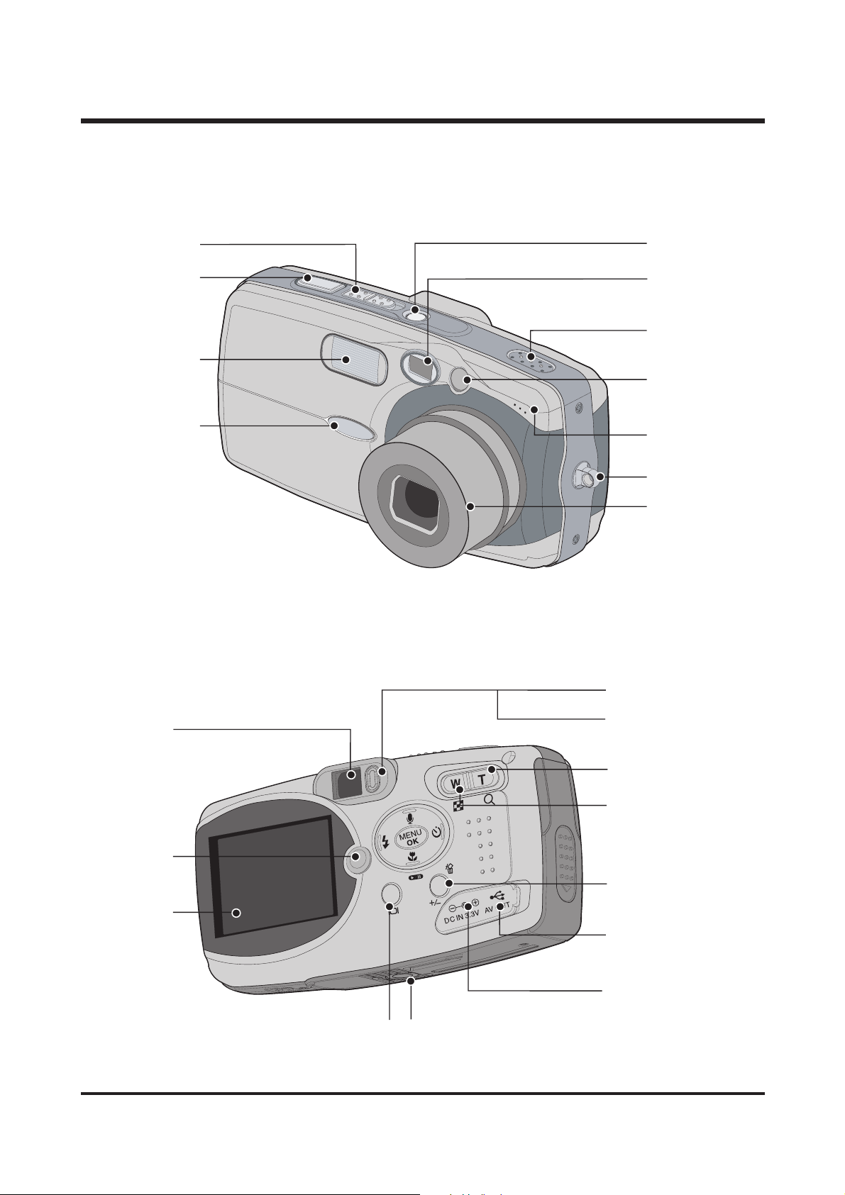
55..
IIddeenn ttiiff ii ccaa ttiioonn ooff ffeeaattuurreess
Mode switch
Shutter button
Flash
Function lamp
Viewfinder
PLAY mode button
LCD monitor
Power button
Viewfinder
Speaker
Auto Focus lamp
Microphone
Strap eyelet
Lens
Autofocus indicator lamp (Green)
Flash indicator lamp (Red)
TELE/ Digital zoom button
WIDE/ THUMBNAIL button
+&-/ DELETE button
USB/ AV connection terminal
DC input connection point
LCD button Tripod socket
Page 9
10
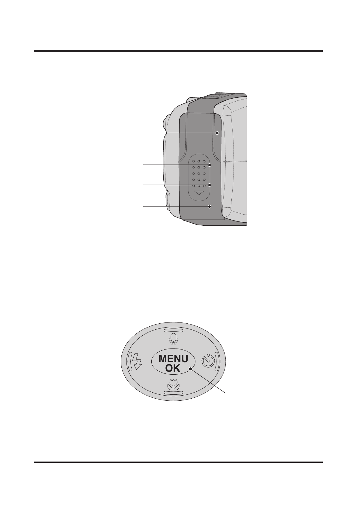
ⅠⅠ.. SS PP EE CC IIFFII CC AA TT II OO NN
Flash/ LEFT button
Menu/ OK button
Macro/ Play/ Pause button
Self-timer/ RIGHT button
Voice memo/ UP button
Memory card slot
Battery chamber
Battery holder
Battery chamber cover
Page 10

11
ⅡⅡ
. INSTALLATION
11.. DDiiggiimmaaxx UU--CCAA 33 SSooffttwwaarree
▶ USB Storage Driver
This enables images to transfer between the camera and PC.
This camera uses the USB Storage Driver as the camera driver. You can use the camera as a USB
card reader.
▶ QuickTime Player
The program for playing back QuickTime movies (.mov). It can also play video files compressed
with MPEG4 codec.
▶ Digimax Viewer 2.1
This is a program for viewing stored images.
You can see the stored images in the memory directly on a PC monitor. You can also copy, move
or delete the images and enlarge /downscale the image sizes with Digimax Viewer. This software is
only compatible with Windows.
▶ MGI PhotoSuite Ⅲ SE
You can edit or store still images that you download from the camera.
This software is only compatible with Windows.
▶DigiStudio: Software for creating 3D avatars.
You can store 3D avatar files on the camera and use one of the avatar as the startup image.
Please be sure to check the system requirements for the software before installing. This software is
only compatible with Windows.
22.. SSyysstteemm RReeqquuiirreemmeennttss
▶ For Windows
PC with processor better than MMX Pentium 233MHz (XP : Pentium II 300MHz)
Windows 98/98SE/2000/ME/XP
Minimum 32MB RAM (XP : 128MB)
140MB of available hard-disk space
USB port
CD-ROM drive
800x600 pixels, 16-bit colour display compatible monitor
(24-bit color display recommended)
▶ For Macintosh
Power Mac G3 or later
Mac OS 9.x ~ 10.2
Minimum 64MB RAM
110MB of available hard-disk space
USB port
CD-ROM drive
QuickTime 4.0 or later for Movie Clip
Page 11
12
33..
PPrrooggrraamm IInnssttaallllaattiioonn
▶ For Windows
Refer to the manual for detailed informatio n on installation..
USB Storage Driver, QuickTime Player, Digimax Viewer 2.1, MGI PhotoSuite Ⅲ SE
▶ For Macintosh
Separated Driver or editing software is not supplied.
Driver for Macintosh use is automatically installed when the camera is turned on.
QuickTime Player is provided as MacOS 9 version in 6 languages.
To install QuickTime Player, select the language folder you want and click execution file.
Then it will be automatically installed.
The folder is composed as follows :
\QT_MacOS 9\English\corresponding execution file.
\Korean\
\Chinese\
\Italian\
\French\
\German\
44.. FFAAQQ
<
For Windows
>
-
Our company aren't responsible for case of using Personal Computer isn't guaranteed from
manufacturer like assembled PC.
▶
When installing
Q1.
Though the Driver CD inserted in CD-ROM Drive, Auto Installation screen is not operate.
How can I install the program?
A1.
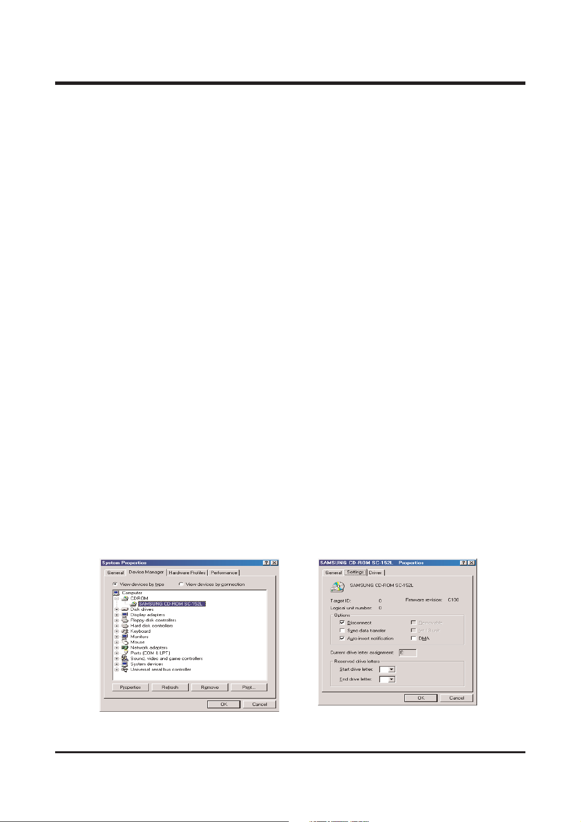
First, It might be occurred if [Auto insert notification], the option to run Auto installation Screen
when the CD inserted was not set. Set 「Auto insert notification」as follows.
If selecting 「Start → Setting → Controller → System → Device Manager → CDROM」
(see Fig. 1), the installed CD-ROM appears. Double click this and then select the setting,
the following frame (see Fig. 2) will be shown.
Select 「Auto insert notification」from the options and reboot the PC.
<
Fig. 1
><
Fig. 2
>
ⅡⅡ.. FF AA QQ
Page 12
13
Second, You need 5~10 seconds for running the automatic setup program according to the
capaility of the computer. If the frame is not displayed even after this, run the
「Windows Explorer」and select 「Samsung.exe」in the CD-ROM drive root directory.
Third, Without running the Auto Installation Screen, run the 「Windows Explorer」and
install the S/W directly at the desired program folder of CD-ROM root directory.
- USB Storage Driver :
Run
「Setup.exe」
in the
「Digimax U-CA 3」
folder
- QuickTime Player :
Run
「QuickTimeInstaller.exe」
in the
「QuickTime Player」
folder
- Digimax Viewer 2.1 :
Run
「Setup.exe」
in the
「Digimax Viewer 2.1」
folder
- MGI PhotoSuite Ⅲ SE :
Run
「Setup.exe」
in the
「MGI PhotoSuite Ⅲ SE」
folder
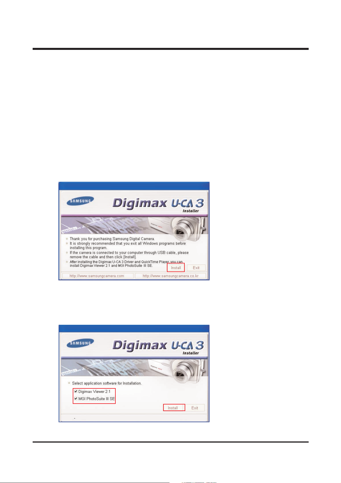
Q2. When is the Digimax U-CA 3 Driver, QuickTime Player installed?
A2. Click the [Install] menu in the Autorun frame.
The U-CA 3 camera driver is installed automatically.
Q3. I'd like to install either Digimax Viewer2.0 or MGI Photosuite III. what should I do?
A3. Please tick off the articles you want to install on the second frame while installing, and click
“Install”.
ⅡⅡ.. FF AA QQ
Page 13
14
Q4. When using One Click Installer,
After installation of Digimax Viewer 2.1 “Restart”message came out. what should I do?
A4. On the “Restart”frame, after installing the Digimax Viewer 2.0, choose “No”then you can go next.
Q5. When using One Click Installer,
I canceled when “Restart”message came out, after installing MGI, but “Restart”message
came out again in the end.
A5. It is because restarting is necessary for using well. It is not an error.
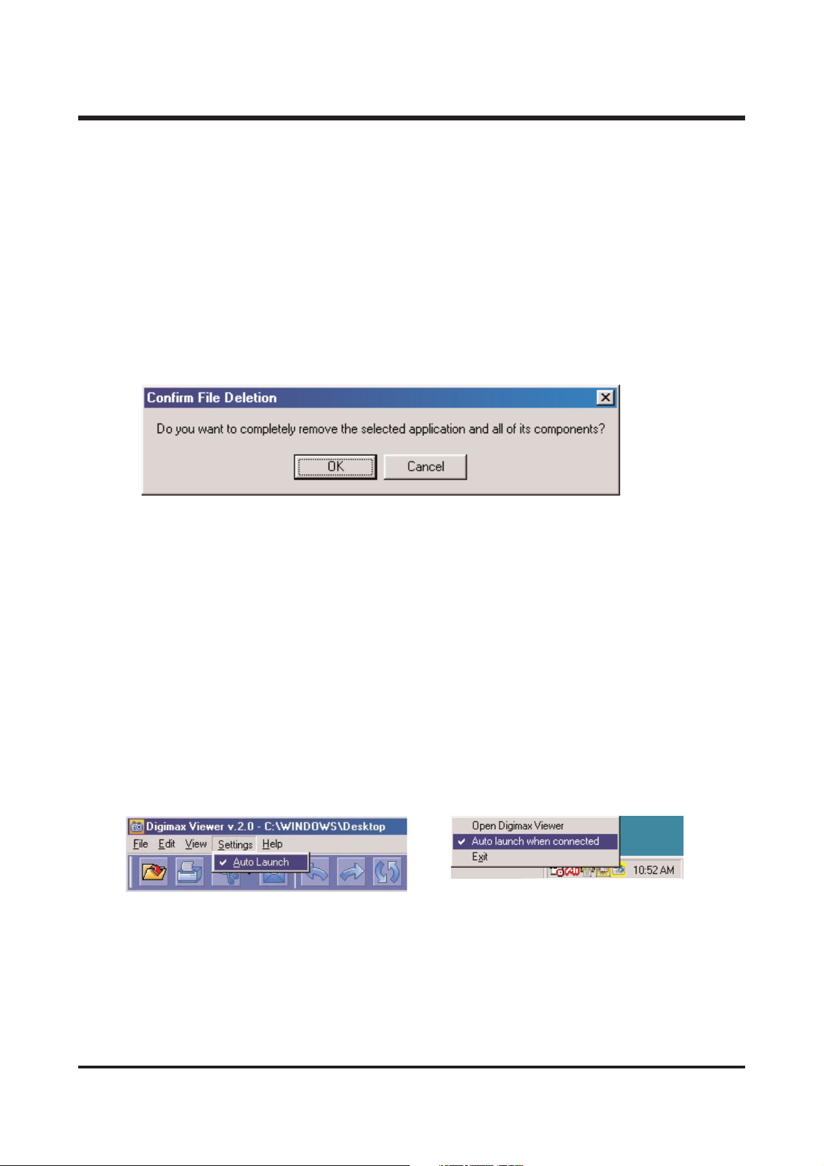
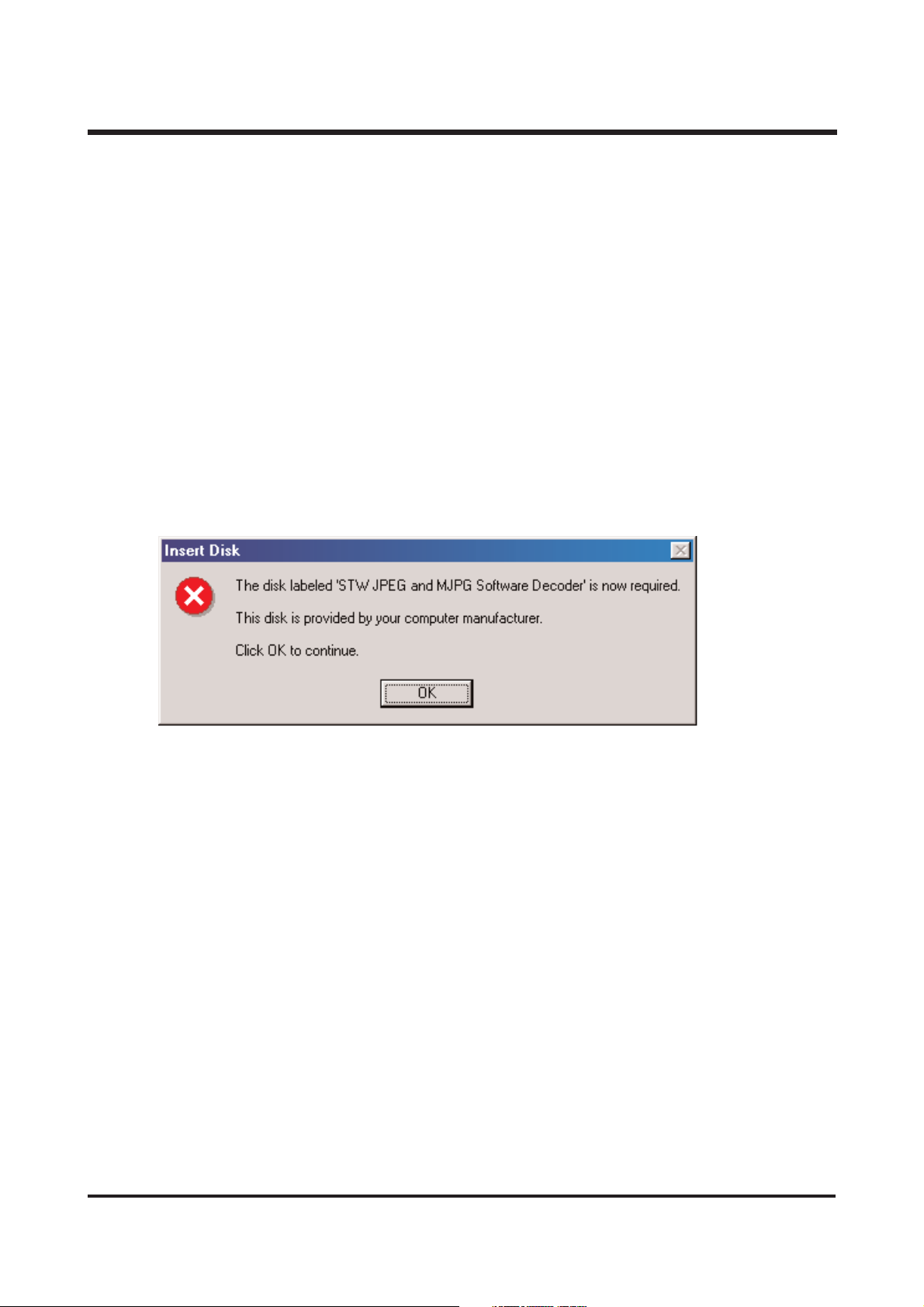
Q6.
I set up driver with supported CD, but screen came out like below. What should I do?
A6.
Though Driver was set up already, if you click USB Storage Driver of set up screen again,
that kind of problem comes out.
At this time, if you choose [Confirm], be careful not to remove a driver.
And in case of using camera continuously, choose [cancel].
▶ Digimax Viewer 2.1
Use
Q1.
If camera is connected, Viewer program operates automatically, but it didn't operate for me.
What should I do?
A1. (1)
Check to adjust PC mode of camera.
(2)
Check to set up Digimax Viewer program.
(3)
Check Digimax Viewer icon on Start Menu working line, and confirm to check
“Auto launch when connected”. If it does, operate automatically.
Or, check "Auto launch when connected in Setting Menu of Viewer program.
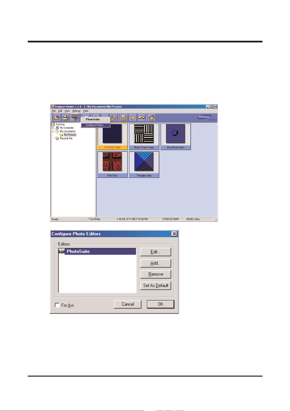
Q2. I want to edit photos by another program. how can i set it up?
A2. Select picture, click the arrow next to edit program, and click the setting up of edit program.
ⅡⅡ.. FF AA QQ
Page 14
15
Then, you see following options.
Edit : editing the name of selected program.
Add : adding different edit program.
Removal : removing added edit program.
Setting up to basic : automatic connection by pressing edit program icon with making the
program basic.
Movie clip : click movie clip, editing movie clip edit program, adding, removing.
Q3. Cannot execute moving picture file taken by Digiman U-CA 3?
A3. Moving pictures taken by Digiman U-CA 3 are MOV file. To execute this, you should install
QuickTime Player in your computer.
ⅡⅡ.. FF AA QQ
Page 15
16
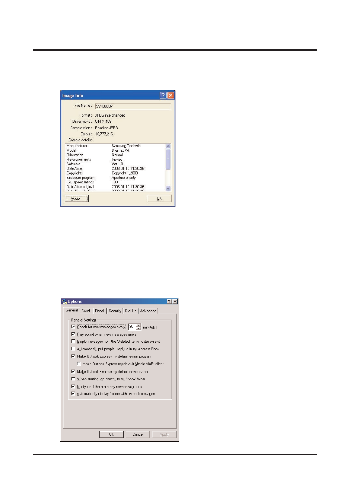
Q4. I want to see the information of voice memo recorded with picture.
A4. Select the picture and select <information> after clicking the right button on mouse, you can
see the information, and click audio icon, you can see the information of voice memo.
Q5. I want to send pictures by e-mail, but e-mail icon is disable.
A5. OS default mail program is not set up.
follow the next..
1. Start microsoft outlook express.
2. Click the option in tool menu.
3. Select following in usual tab.
- using outlook express to basic mail program.
- using outlook express to basic MAPI client.
4. Click <yes>, after message scene comes up.
5. You can use e-mail with rebooting the system.
ⅡⅡ.. FF AA QQ
Page 16
17
ⅡⅡ.. FF AA QQ
Q6. The icon of edit program, information,ect.. is not active, after selecting many pictures.
A6. The edit program connection and entry information,ect.. is only possible with one picture.
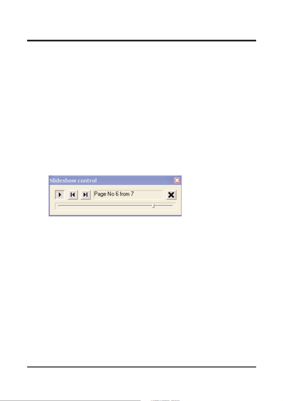
Q7. First cycle of slide show is going slowly.
A7. Because buffering time is long. the slide show will be shown as selected from next.
Q8. The thumbnail picture taken by small size(640x480) is dim.
A8. The system brings the thumbnail information of exif which is saved together, when taken.
Q9. I select “fix ratio”by clicking the right button on mouse, and click the “fix ratio”,
but it doesn't disappear.
A9. The right button on mouse allows “fix ratio”only. click <display> and select different option.
Q10. How to stop the slide show temporally on process?
A10. Please click the play button once more.
Q11. Some image has detailed entry information, but any image hasn't. why?
A11. There is an entry information made by camera only. because this is recorded when you
take a picture. if you change the format of image made from camera, or size, you can't see
entry information any more.
Q12. If you do another job (down the mouse scroll bar, execute another job minimizing viewer)
on loading the image of camera, the computer takes it slowly.
A12. That's for stability. abstain from doing another job on loading image.
Q13. When i select the <detail> in <example>, i can't see which image is selected.
A13. It is selected that the light of file name is changed to red character in <detailed>.
Q14. How can i select the center image in <big icon> or <small icon>?
A14. Select the image you want by click, pressing CTRL key.
Page 17
18
ⅡⅡ.. FF AA QQ
Q15. I can't see the folder made in background scene in the foider tree of digimax viewer 2.1
A15. Click the <RENEWAL> button, after executing made folder. otherwise, turn the digimax viewer 2.1
on and off.
Q16. I try to use digimax viewer 2.1 connecting with the camera of another company, or card reader
machine, but it's working slowly, or not working.
A16. That's not a problem with program, because digimax viewer 2.1 is made for digimax only.
you can use it after taking another camera or card reader machine off.
Q18. When can i use <undo>,<restoration>?
A18. You can use <changing name>, <changing all name of file> on searcher, or <rotation>,
<a change of image size>.
Q19. I try to execute after setting up viewer, but there is an error message like following.
A19. This error can not be mutual dll file (ex. oleaut32.dll, olepro32.dll, asycfilt.dll, stdole2.tlb)
installed in the system.
refer to http://support.MICROSOFT.com/default.aspx?scid=kb;en-us;321915
1. When microsoft office 2000 or office 2000 compenent is installed, visit
http://microsoft.com/office/previous/default.htm,and get the office 2000 service release 1 (sr-1),
and install it.
2. You have to install mcrepair.exe if there is no microsoft office 2000 or office 2000 component.
visit http://www.microsoft.com/download/msninvestor/patch/1.0/win98/en-us/mcrepair.exe,
and save the file of mcrepair.exe to background scene and then, reboot the computer
after installing mcrepair.exe.
Page 18
19
ⅡⅡ.. FF AA QQ
<For Macintosh>
- When purchsing Macintosh computer, check installed over MacOS 9.0 and USB Mass
StorageSupport 1.3.5
- Not guarantee of USB operating in PC has Mac OS and Mac OS USB Mass Storage Support
upgrading.
Q1.
Is Driver supported for Macintosh?
A1.
It is not additionally for Macintosh, but you can use this driver in over Mac OS 9.X
Connect a camera to Macintosh with USB cable, after power on, it is recognized as Unknow
name disk automatically.
Q2.
How can I check the USB version in iMac?
A2.
Click in the order of “Apple System Profiler- Device and volume”and the USB version is shown.
If the USB version is 1.0.1, updating is needed. But if it 1.1, you can use it without updating.
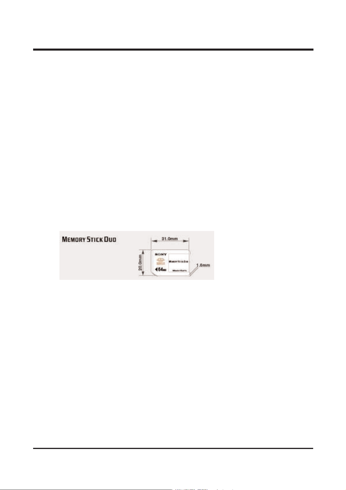
MMEEMM OO RRYY SSTTIICC KK DDUUOO
Memory Stick Duo is composed of micro Media(20×31×1.6mm) and cartridge which you can use with
or without.
※※ DDoonn''tt ffoorrmmaatt mmeemmoorryy ssttiicckk dduuoo oonn tthhee ccoommppuutteerr..
IInn ccaassee yyoouu ffoorrmmaatt iitt oonn PPCC,, iitt iiss iimmppoossssiibbllee ttoo uussee MMEEMMOORRYY
SSTTIICCKK DDUUOO iinn tthhee ccaammeerraa..
TThheerreeffoorree,, bbee ssuurree ttoo ffoorrmmaatt mmeemmoorryy ssttiicckk dduuoo iinn tthhee ccaammeerraa..
Page 19
UU SSBB CCHHEECCKK
▶ How can I check of the USB Interface available in my PC?
- Check the OS installed in PC.
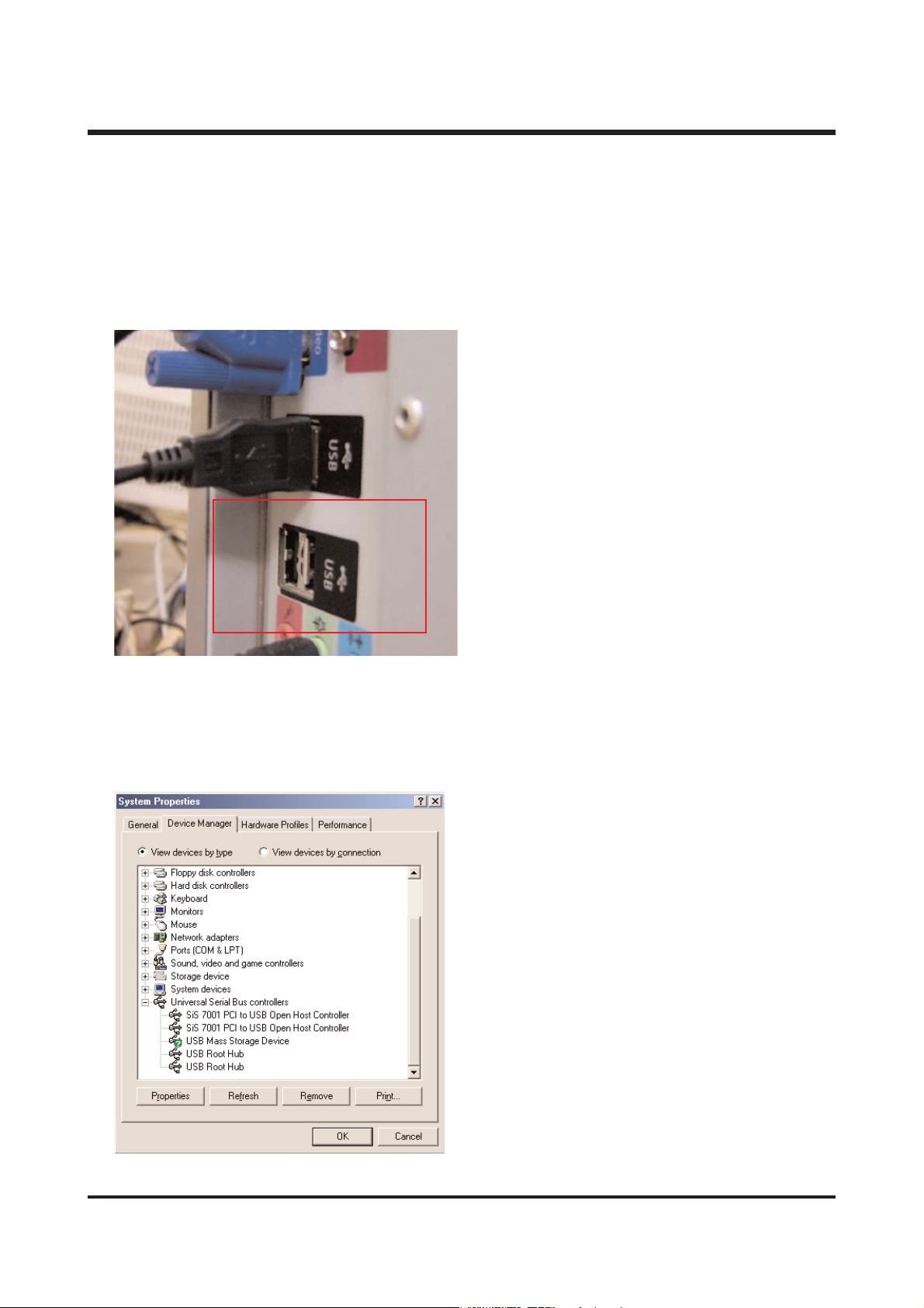
1) Check if the USB ports located in the back of the body or keyboard to connect the USB cable as
shown in the figure.
The USB Interface is enabled in Windows 98 or
later(Windows 98, 98SE, 2000, ME)
Windows 95 OSR 2.1 or later.
It should be met with the following three
requirements.
For other details about USB, see http://www.usb.org.
2) if [Universal Serial Bus(USB) Controller] located in the System Device Manager. Check as follows,
Click 「Start → Setting → Controller → System → Device Manager→ Universal Serial Bus Controller」
sequentially.
Then there should be the USB Host Controller
and USB root hub in the USB controller.
20
ⅡⅡ.. FF AA QQ
Page 20
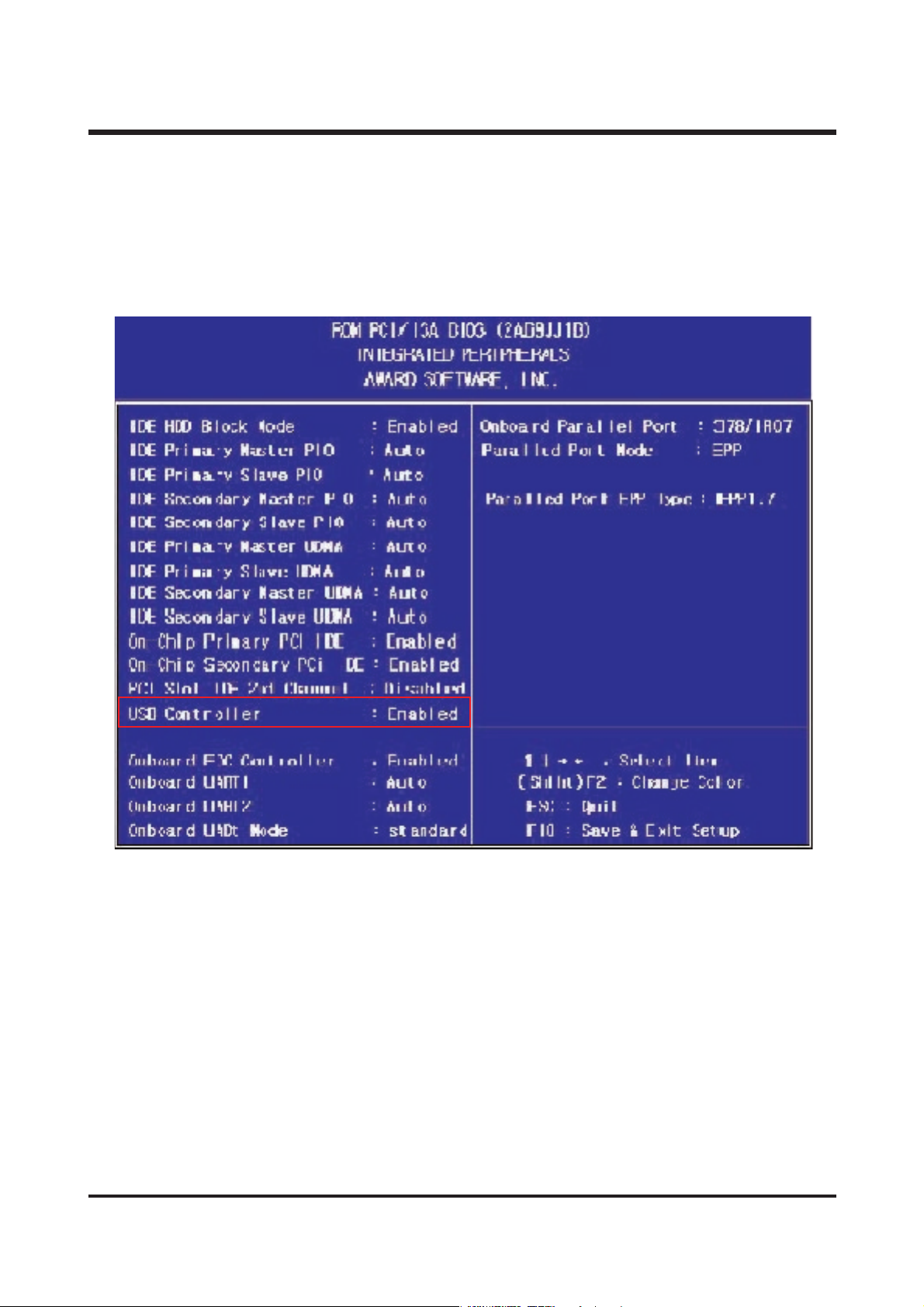
3) Is CMOS(BIOS) is set to Enable?
If you examine the first screen which appears right after turning on the computer, you can find
the key for each bios CMOS SETUP.
The keys are different depending on each bios. Use Del key for AWARD, F1 for AMI, and F2 for
MR. If you press the corresponding key, you can directly go to the CMOS SETUP screen
To use USB properly, USB Controller should be set to Enabled.
21
ⅡⅡ.. FF AA QQ
Page 21
22
ⅡⅡ.. FF AA QQ
HHoo ww ttoo cchhee cckk tthhee UU SS BB ssttaa ttuu ss oonn tthhee PP CC aaff tteerr ccoo nn nn eecc ttiinngg CCaa mmeerraa !!
▶ Win 98 and 98SE don’t have the system file to support USB !
You must install the driver in the CD provided with camera on the computer.
① Windows/inf/other/uc1.inf
② Windows/system/iosubsys/dscpdr.pdr
③ Windows/system32/drivers/DSCUC1.sys
☞ Win 2000, ME, XP support the USB system file itself, so the camera will be automatically read on
the computer when connected to the PC.
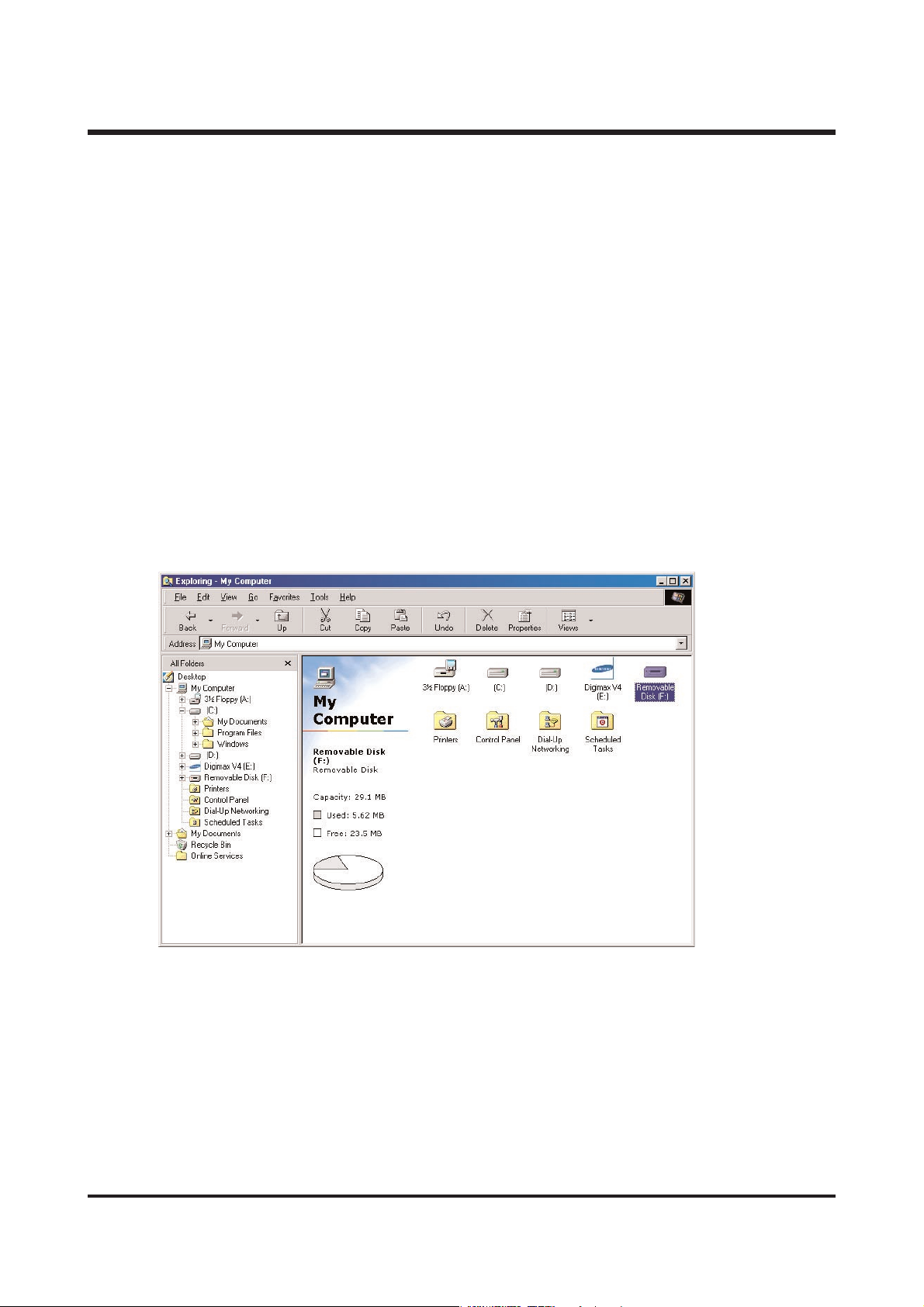
▶ How can I check if the USB Storage driver has been installed successfully?
camera to the PC with the provided USB cable and turn it on at the PC mode.
Then the following is shown.
(1) Removable disk appears.
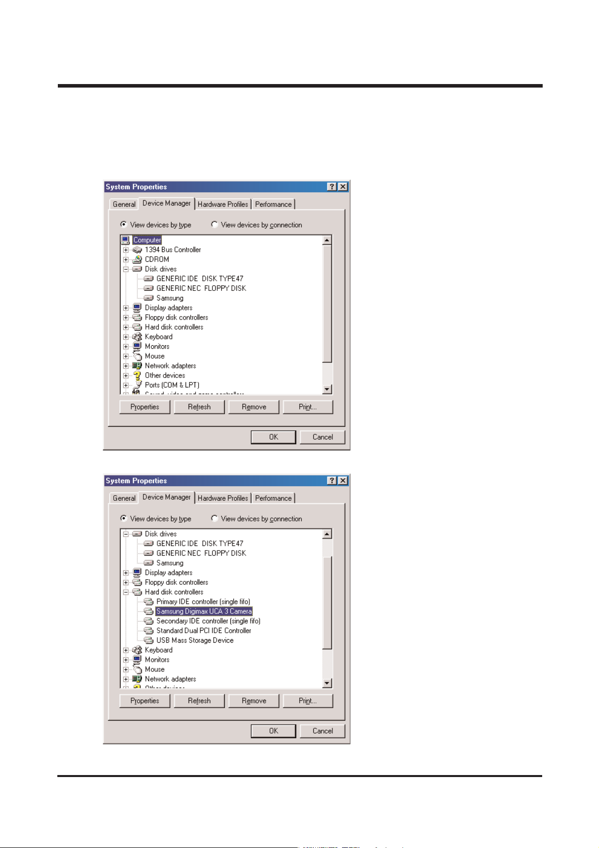
(2) In the system properties, the device state is indicated as “The device is working properly.”
1) Windows 98, Windows 98SE
▷ Start ▷Control Panel ▷ System ▷ Device Manager
2) Windows ME
▷ Start ▷ Control Panel ▷ System ▷ Device Manager
3) Windows 2000
▷ Start ▷Settings ▷ Control Panel ▷ System ▷ Hardware ▷ Device Manager
4) Windows XP
▷ Start ▷ Control Panel ▷ System ▷ Hardware ▷ Device Manager
Page 22
23
ⅡⅡ.. FF AA QQ
< Win 98/98SE >
-
Disk drives
: SAMSUNG
-
Universal Serial Bus(USB) controller
: Samsung U-CA3 Camera
-
Storage device
: USB Mass Storage Device
Page 23
24
ⅡⅡ.. FF AA QQ
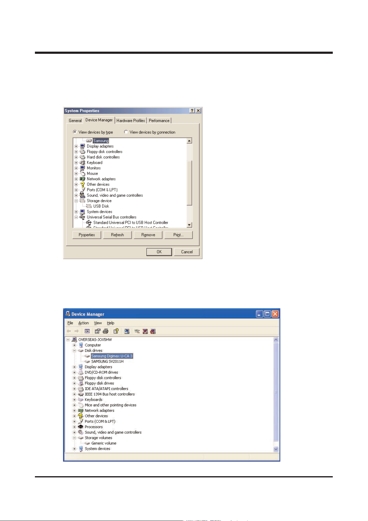
< Win ME >
-
Disk drives
: SAMSUNG
-
Universal Serial Bus(USB) controller: USB Mass Stroage Device
-
Storage device: USB Disk
< Win 2K / XP >
-
Disk drives
: SAMSUNG DIGIMAX U-CA3
-
Universal Serial Bus controller: USB Mass Storage Device
-
Storage volume: general volume
Page 24

25
ⅡⅡ.. FF AA QQ
(3)
Please check as belows files are installed or not.
< Windows 98 / 98SE >
U-CA3.inf : Windows/inf/other
DSCPDR.pdr : Windows/system/iosubsys
DSCUC1.sys : Windows/system
< Windows ME / 2000 / XP >
usbstor.sys : Windows/system32/drivers
usbstor.inf : Windows/inf
<NOTE> Necessary file When using storage
1. Windows 2000
winnt/system32/drivers/disk.sys
usbstor.sys
winnt/inf/usbstor.inf
disk.inf
2. Windows ME
windows/system32/drivers/usbntmap.sys
usbstor.sys
windows/system/iosubsys/usbphlp.pdr
windows/inf/usbntmap.inf
usbstor.inf
3. Windows XP
windows/system32/drivers/disk.sys
portmgr.sys
usbstor.sys
volsnap.sys
Page 25

26
ⅡⅡ.. FF AA QQ
-- 9988 // 9988SS EE
IIff yyoouu ttrryy ttoo iinnsstt aallll DDrrii vvee rr aa fftt eerr ccoonnnneecc ttiinn gg yy oo uurr cc aa mm eerraa ,, tthhee aabb oovvee pprroobbllee mm wwiillll
hh aa pp ppee nn ..
TToo aavvooiidd tthh iiss,, ppll eeaa ss ee iinnsstt aallll UUSS BB MMaass ss SSttoorraaggee ddrrii vveerr ffiirrsstt aa nn dd tthh eenn ccoonnnnee cctt tthhee
ccaa mm eerraa ..
(1) If you connect USB cable before installing Driver.
1. Select [Other Devices] from Device Manager and delete it.
2. Install the driver.
3. Restart the system.
4. Connect USB cable.
(2) When connecting USB cable after installing Driver
1. Select [Other Devices] from Device Manager.
2. Go to the [Properties] by clicking the right button of the mouse.
3. Click [Reinstall Driver].
4. After selecting [Specific Location] from [Have Disk], go to the next step.
5. Select [search] from [Copy manufacturer’s files from] and choose Windows/inf/other.
And then check if there is U-CA3.inf and select it.
-- MMEE // 220000 00 // XX PP
This kind of problem occurs in the process of installation if you disconnect USB cable while
loading images or when there are not usbstor.sys and usbstor.inf 1000500140 (or required files <notes> files needed to use storage)
1. Click the right button of the mouse and delete it.
2. Disconnect the camera and PC.
3. Check if there is usbstor.sys and usbstor.inf and restart the computer.
4. Connect the camera and use it.
▶ How to remove the Registry?
※※ CC AAUUSS IIOONN
① Registry is the place where the important information of computer is saved and managed.
Use extreme caution when removing Registry.
② If you remove a folder which is not supposed to be removed, the computer may not function
properly. → Reinstall O.S.
③ You must backup the registry before removing it.
▶ Running Registry edit
① START → RUN (Same to other O.S)
Input “regedit”and click “ok”
Page 26

27
ⅡⅡ.. FF AA QQ
Input “VID_0839&pid_1015”and Click the Find next and press F3 to find out the folder.
Select VID_0839&PID_1015 from “HKEY_LOCAL_MACHINE\ENUM\USB" folder and delete it.
(In case of Windows 2000/XP, use registry editor. Don't follow the above instructions to delete.)
Page 27

28
ⅡⅡ.. FF AA QQ
▶
When transmitting amounts of image data, what is required detail?
When transmitting amounts of image data, it may not have enough virtual memory of system.
For this, increase virtual memory like this.(based on Win 98SE)
1.
[Start] -> [Settings] -> [Control Pad].
2.
Click the [System], open “system register information”.
3.
In “Efficiency”, “Advanced Settings”Press “Virtual memory”button.
4.
Press “User manage virtual memory setting directly”of virtual meomory.
5.
In virtual memory screen, increase each minimum(MB) and maximum(MB).
6.
If you press “OK”button, it finish virtual memory settings.
▶
I copied a file from computer to camera, but it wasn't recorded in camera.
Because you operate a camera during you are working on PC. So, when operating works ;
copying file of Removable disk to computer, deleting and copying file in computer to portable disk,
green lamp of side view finder of camera is on and off. When green lamp is off completely,
it means operating work finish correctly. Before this, not to do another work ; USB cable
disconnect.
Page 28

29
ⅡⅡ.. FF AA QQ
▶ If [New Hardware Found Wizard] appease, although you have already used after installing Driver
and connected USB cable to the USB port you used before.
This problem occurs ;
1. When a memory card is not inserted correctly
2. When a memory card is not properly formatted.
3. Please connect USB cable after checking if a memory card is inserted correctly.
4. If the memory card is not formatted properly, please reformat if from the camera.
If you cannot format it from the camera, format on the computer using U-CA3 format program.
(Don't format from the Window exploer.When formatting after connecting memory card through
a card reader, we recommend to use the card reader of memory card manufacturer. If not,
we don't guarantee successful completion of formatting.)
-
If using the VIA chipset
If using the VIA chipset, USB communication might not operate normally in some case.
The patch file of USB Filter Driver is also registered in the website of VIA Technology Inc.
Install the patch file and then use it. You can find the patch file in the following URL.
http://www.viatech.com/drivers or samsungcamera.com
-
If using AMD processor and VIA USB Controller
AMD Processor more than 350MHz
USB controller of VIA Technologies
It has been known that there being the problem in the USB operation between Microsoft
Windows 98SE version and the above hardware, so the patch file is registered in the Microsoft
Website. Download and install the patch file.
You can find the patch file in the following URL.
http://support.microsoft.com/support/kb/articles/Q240/0/75.asp
patch file name
: 240075up.exe
(Ref) It has been modified in Windows ME(Millennium Edition).
-
Using Intel chipset
The patch file concerning the Intel chipset is registered in the Intel website.
Download the required file from the following website and then upgrade the system.
http://developer.intel.com/design/software/drivers/platform/inf.htm
Page 29

30
55.. AAbboouutt AAVVAATTAARR
▶ DigiStudio requires the following minimum system configuration for smooth 3D performance.
If your system does not meet the requirements, you will receive error messages and the installation
will not continue.
▶ The following graphic cards do not support 3D acceleration and cannot be used with DigiStudio :
(1)ATI 3D (Charger /Pro Turbo /Xpression)/All in wonder pro
(2)ATI Rage (ⅱ/iic)/Rage 3D(LT Pro /Pro)/Xpert (98 /@play)
(3)nVidia Riva 128
(4)3dfx Voodoo 2
(5)SiS (6215A0 /6125B0 /6215C /5598 /530 /620 /540)
(6)Intel i740 graphics chip
(7)Hercules Terminator Beast
(8)Trident 3D /Blade /CyberBlade
(9)Diamond Multimedia FireGL 1000 Pro
(10)Number 9 SR9
※※ DDeeppeennddiinngg oonn yyoouurr ggrraapphhiiccss ccaarrdd,, 33DD aavvaattaarrss mmaayy nnoott bbee ssuuppppoorrtteedd..
Recommended System Requirements
Minimum System Requirements
CPU Intel Pentium2-400MHz Intel Pentium3-500MHz
RAM 64MB 128MB
Video Card
Graphic card with 3D acceleration and at Graphic card with 3D acceleration and at
least 16MB of video RAM least 8MB of video RAM
Sound Card
16-Bit Stereo Sound Card
Hard Disk 150MB or more available space
Operating System
Windows 98SE / ME / 2000 / XP
Web Browser
Internet Explorer 5.0 or later
ⅡⅡ.. FF AA QQ
Page 30

31
▶ When installing the DigiStudio, but there is an error message like following.
- The message box will state the reason for termination (e.g. “Not enough memory”), and the
installation program will stop the process.
▶ When DirectX 8.1 has not been installed.
- If DirectX 8.1 is not detected on your computer, the install wizard 8.1 and, when completed, will
will install DirectX reboot.
▶ When QuickTime 6.3 has not been installed.
- The program will operate normally, but you will not be able to create MOV files when you press the
‘Create Video’button. To create MOV files, close the program, install QuickTime 6.3, and run the
program once more.
ⅡⅡ.. FF AA QQ
Page 31

32
▶ When the screen does not display correctly, even though DirectX 8.1 has been installed.
- Check as belows ;
● To check the manufacture of graphic cards,
click the right button of your mouse on
the desktop and go to ‘display properties’
→‘setting’. Then you can check from the
Display in the middle screen.
- Resoultion : 1024 X 768 or higher.
- Color : High color 16Bit or True 32Bit
ⅡⅡ.. FF AA QQ
Page 32

33
▶ How to check your graphic card compatibilily?
- Go to [ Start Start → Run ], write “dxdiag dxdiag”and press Enter key key.
- When DirectX 8.1 has not been installed (or this program has not When DirectX been installed)
You can find RAM information in ‘Control Panel -> System -> General’. CPU information is
displayed when the computer is turned on.
ⅡⅡ.. FF AA QQ
Page 33

34
▶ In case you can’t make moving picture creation installing QuickTime 6.3. file after installing
QuickTime 6.3.
- As QuickTime Installation Type is set to Minimum, you can’t make moving picturet creation file.
Uninstall QuickTime and reinstall the version in the provided DigiiStudio CD.
※ When installing it, be sure to set to [Recommended].
▶ When you can’t make moving picture creation file, after uninstalling QuickTime and restalling the
version as instructed.
- When Uninstalling, you have to select [Uninstall Everything] to remove all of the existing files.
If you selecte “Uninstall Uninstall”, the already created system will be used.
ⅡⅡ.. FF AA QQ
Page 34

35
▶ How to check your graphic card compatibilily?
- Go to [ Start Start → Run ], write “dxdiag ”and press Enter key.
After selecting Display Menu, click Test Direct 3D button and test 3D.
ⅡⅡ.. FF AA QQ
Page 35

36
66.. PPiiccttBBrriiddggee
▶ About PictBridge.
CIPA standard “CIPA DC-001"(PictBridge) provides direct connecting solution to image input/output
devices by standardizing application service for image input/output devices. The first PictBridge
release focuses on direct printing service between DSC and printer.
▶ PictBridge system architecture
As for PictBridge, DSC is directly connected to the printer through USB cable as shown below.
DSC serves as a “device”of USB, and printer works as a “Host”of USB.
▶What kind of printers support PictBridge?
- When the printer supports PictBridge, PictBridge logo is attached on it.
ⅡⅡ.. FF AA QQ
Page 36

37
▶ How to use on the camera
- Changing Menu of camera.
MENU -> SET -> USB -> PRINT -> OK
- Connecting the Camera to a Printer.
1. Press the POWER button to turn on the
camera.
2. In a mode other than Voice Recording mode,
press the MENU button.
3.
Press the LEFT/ RIGHT button and select [SETUP]
menu tab.
4. Select [USB] menu by pressing the
UP/ DOWN button and press the RIGHT button.
5. Select [PRINTER] menu by pressing the
UP/ DOWN button and press the OK button.
6. Press the menu button twice and the menu
will disappear.
7. Use the supplied USB cable to connect the
camera to the printer as shown below.
ⅡⅡ.. FF AA QQ
Page 37

38
- You can select the scope of the PictBridge function.
IMAGE, SETUP, PRINT, DPOF, RESET
- If [CUSTOM] is selected.
· SIZE
· LAYOUT
· PAPER
· QUALITY
· DATE
· FILE NAME
ⅡⅡ.. FF AA QQ
Page 38

39
Warring message cause & solution
cause :
in case there is something wrong with USB
printing settings.
solution :
set to USB printing.
MENU -> SETUP -> USB -> PRINT -> OK
cause :
when there is no MEMORY CARD in the camera.
solution :
insert the MEMORY CARD.
cause :
- when there is no image in the MEMORY CARD.
- in case there is no image set in the PRINTER.
solution :
- After taking IMAGEs, try again.
- After setting IMAGEs, print them.
cause :
when PRINTER is out of ink.
solution :
replace INK.(When message pops up when
printeris in the process of preparation.)
cause :
in case there is no paper in the PRINTER.
solution :
supply PAPER.(When message pops up when
printeris in the process of preparation.)
cause :
Data cannot be processed as over 100 images
are taken.
solution :
limit the number of IMAGEs below 100.
※ BUFFER which processes data of images in
the camera is 128KByte.
cause :
when PRINTER is out of ink and no paper in the
PRINTER.
solution :
replace INK. and supply PAPER.
※ When message pops up when printer is in
the process of printing.
SSEETT UUSSBB
▶ Solution for each ERROR Message.
NNOO CCAARRDD
NNOO IIMMAAGGEE
NNOO IINNKK
NNOO PPAAPPEERR
OOUUTT OOFF NNUUMMBBEERR
ⅡⅡ.. FF AA QQ
Page 39

40
1. MAIN ASSEMBLY
ⅢⅢ.. EEXXPPLLOODDEEDD VVIIEEWWSS AANNDD PPAARRTTSS LLIISSTT
1-5
1-4
1-3
1-1
1-6
1-2
1-6
Page 40

41
Fig.No. Parts No. Parts Name Q'ty Remarks
1-1 Q9007195501A FRONT COVER ASS'Y-KENOX UCA-3 1 SILVER
Q9007196101A FRONT COVER ASS'Y-DIGIMAX UCA-3 1 SILVER
Q9007196201A FRONT COVER ASS'Y-DIGIMAX UCA-3 1 WHITE
Q9007196301A FRONT COVER ASS'Y-KENOX UCA-3 1 WHITE
Q9007196401A FRONT COVER ASS'Y-DIGIMAX UCA-3 1 GRAY
Q9007196501A FRONT COVER ASS'Y-KENOX UCA-3 1 GRAY
1-2 Q7012076401B DECORATION RING 1
1-3 Q9007195601A BACK COVER ASS'Y 1 SILVER
Q9007196601A BACK COVER ASS'Y 1 WHITE
Q9007196701A BACK COVER ASS'Y 1 GRAY
1-4 Q6003040701A SCREW 1
1-5 Q7309039901A SCREW CAP 1
1-6 Q6003024201A SCREW 6
ⅢⅢ.. EEXXPP LL OO DD EEDD VVII EE WWSS AA NNDD PPAA RR TTSS LL IISS TT
▶▶
PARTS LIST
Page 41

42
2. BODY ASSEMBLY
ⅢⅢ .. EEXXPP LL OO DD EEDD VVII EE WWSS AA NNDD PPAA RR TTSS LL IISS TT
2-10
2-5
2-7
2-9
2-6
2-8
2-4
2-2
2-32
2-42
2-31
2-35
2-41
2-33
2-29
2-26
2-34
2-36
2-19
2-21
2-44
2-1
2-3
2-12
2-18
2-43
2-45
2-16
2-39
2-17
2-20
2-40
2-24
2-28
2-30
2-27
2-25
2-15
2-46
2-22
2-13
2-23
2-14
2-11
2-37
2-38
Page 42

43
▶▶
PARTS LIST
ⅢⅢ.. EEXXPP LL OO DD EEDD VVII EE WWSS AA NNDD PPAA RR TTSS LL IISS TT
Fig.No. Parts No. Parts Name Q'ty Remarks
2-1 Q9002120101A UC1 BARREL ASS'Y 1
2-2 Q9003020001A FINDER ASS'Y 1
2-3 Q9761173507 SCREW 3
2-4 Q2904001401A OLPF 1
2-5 Q7309039401A OLPF CUSHION 1
2-6 Q9008064801A CCD FPCB ASS'Y 1
2-7 Q4102007401A CCD FPCB 1
2-8 Q0604002501A CCD SENSOR 1
2-9 Q7011044101A CCD PLATE 1
2-10 Q9761173507 SCREW 2
2-11 Q7211066201A BATTERY CHAMBER_A 1
2-12 Q7211066301A BATTERY CHAMBER_B 1
2-13 Q7217284601A BATTERY LOCK 1
2-14 Q7217284701A BATTERY LOCK SLIDER 1
2-15 Q7017037101A BATTERY PLATE 1
2-16 Q7017037201A BATTERY CONTACT_A 2
2-17 Q7017037301A BATTERY CONTACT_B 1
2-18 Q7017037401A BATTERY LOCK PLATE 1
2-19 Q7411092902A BATTERY HINGE_A 1
2-20 Q6107054601A BATTERY SPRING 1
2-21 Q6107054501A BATTERY HINGE SPRING 1
2-22 Q6107056001A BATTERY LOCK SPRING 2
2-23 Q0462911701A TAP TITE SCREW 1
2-24 Q9008065201A REFLECTOR ASS'Y 1
2-25 Q7211066401A FRESNEL LENS 1
2-26 Q7211066501A REFLECTOR HOLDER 1
2-27 Q7014004201A REFLECTOR 1
2-28 Q7309039701A TUBE RUBBER 2
2-29 Q7409148801A REFLECTOR SHIELD 1
2-30 Q0611003301A XE TUBE 1
2-31 Q4102007501A TRIG FPCB 1
2-32 Q2401007501A MAIN CONDENSOR 1
2-33 Q3708005501A MEMORY STICK DUO CONNECTOR 1
2-34 Q4101026901A USB EXT FPCB 1
2-35 Q4101027001A LCD EXT FPCB 1
2-36 Q9008065701A MAIN PCB SMD ASS'Y 1
2-37 Q9008065901A POWER PCB ASS'Y 1
2-38 Q0961900301A SCREW 1
2-39 Q9008065401A JACK PCB ASS'Y 1
2-40 Q0961900301A SCREW 1
2-41 Q4101026801A AUDIO FPCB 1
2-42 Q4719001801A SPEAKER 1
2-43 Q0902007801A MIC 1
2-44 Q0601004601A AF LED 1
2-45 Q7211028902A TRIPOD CONNECTOR 1
2-46 Q7217284503B BATTERY COVER 1 SILVER
Q7217294501A BATTERY COVER 1 WHITE
Q7217294601A BATTERY COVER 1 GRAY
Page 43

44
3. BARREL ASSEMBLY
ⅢⅢ.. EEXXPP LL OO DD EEDD VVII EE WWSS AA NNDD PPAA RR TTSS LL IISS TT
3-36
3-58
3-35
3-30
3-33
3-1
3-32
3-34
3-37
3-31
3-3
3-2
3-10
3- 23
3-22
3-4
3-21
3-28
3-26
3-25
3-29
3-55
3-27
3-24
3-5
3-11
3-20
3-12
3-6
3-18
3-53
3-7
3-38
3-17
3-22
3-19
3-15
3-16
3-13
3-8
3-14
3-54
3-44
3-42
3-46
3-9
3-41
3-40
3-57
3-45
3-49
3-51
3-56
3-52
3-39
3-47
3-48
3-50
Page 44

45
ⅢⅢ.. EEXXPP LL OO DD EEDD VVII EE WWSS AA NNDD PPAA RR TTSS LL IISS TT
Fig.No. Parts No. Parts Name Q'ty Remarks
3-1 Q9002120001A LENS BASE ASS'Y 1
3-2 Q7212172505A LENS BASE 1
3-3 Q7411097601A AF GUIDER BAR_A 1
3-4 Q7411097701A AF GUIDER BAR_B 1
3-5 Q7411085902A ZOOM GEAR_A SHAFT 1
3-6 Q7411097801A ZOOM GEAR_B SHAFT 4
3-7 Q7411090001B ZOOM GEAR_C SHAFT 2
3-8 Q7411097901B ZOOM GEAR_D SHAFT 1
3-9 Q3107001701A ZOOM MOTOR 1
3-10 Q9611142007 SCREW 2
3-11 Q7212160001B ZOOM MOTOR GEAR 1
3-12 Q7212160101A ZOOM GEAR_A 1
3-13 Q7411085802A ZOOM GEAR_D 1
3-14 Q7411085702A ZOOM GEAR_C 1
3-15 Q7411085601B ZOOM GEAR_B 1
3-16 Q7212160602B ZOOM GEAR_E 2
3-17 Q7212172701A ZOOM GEAR_H 3
3-18 Q7212173801A ZOOM GEAR_G 1
3-19 Q7212172601A ZOOM COVER 1
3-20 Q7012075903A ZOOM COVER_B 1
3-21 Q9761142507 SCREW 1
3-22 Q0961900301A SCREW 2
3-23 Q9008062101A MAIN FPCB ASS'Y 1
3-24 Q4101025801A MAIN F PCB 1
3-25 Q9002104301A AF MOTOR ASS'Y 1
3-26 Q4101026701A ZOOM MOTOR FPCB 1
3-27 Q0608001001A PHOTO INTERRUPTER 2
3-28 Q0608000701A PHOTO REFLECTOR 1
3-29 Q7012076001A AF PI CAP 1
3-30 Q9002121701A 3rd LENS BARREL ASS'Y 1
3-31 Q9002119301A 3rd LENS ASS'Y 1
3-32 Q7012069406C AF LIMIT SPRING 1
3-33 Q6001014001A SCREW 1
3-34 Q6107048305A 3RD LENS BARREL SPRING 1
3-35 Q7212174303A AF GUIDE HOLDER 1
3-36 Q0961900101A SCREW 1
3-37 Q0994913101A SCREW 1
3-38 Q6003040401A SCREW 2
3-39 Q7212172103A GUIDE PLATE 1
3-40 Q9002119401A 2nd LENS BARREL ASS'Y 1
3-41 Q9002119101A 2nd LENS ASS'Y 1
3-42 Q9005017101A SHUTTER ASS'Y 1
3-43 Q0961900301A SCREW 2
3-44 Q7409137303C SHUTTER SHIELD 1
3-45 Q7411085305A 2ND MOVE PIN 3
3-46 Q7012075703A F_PCB GUIDER 1
3-47 Q7212172003A ZOOM RING 1
3-48 Q7212171702A SLIP RING 1
3-49 Q7012075502A 1ST PUSH PLATE 1
3-50 Q7411097502A 1st MOVE PIN 3
3-51 Q7212172201A CAM BARREL 1
3-52 Q7012075802A FINDER HOLDER 1
3-53 Q9002119501A OUTER GUIDE BARREL ASS'Y 1
3-54 Q7212172303A OUTER CAM BARREL 1
3-55 Q9761173007 SCREW 5
3-56 Q9002119001A 1st LENS ASS'Y 1
3-57 Q7409138001A FRONT SHIELD 1
3-58 Q7012069301A AF CLIP 1
▶▶
PARTS LIST
Page 45

46
ⅢⅢ.. EEXXPP LL OO DD EEDD VVII EE WWSS AA NNDD PPAA RR TTSS LL IISS TT
4. FRONT COVER ASSEMBLY
4-1
4-18
4-2
4-16
4-13
4-6
4-7
4-9
4-17
4-14
4-3
4-4
4-8
4-5
4-10
4-15
4-19
4-12
4-11
Page 46

47
Fig.No. Parts No. Parts Name Q'ty Remarks
4-1 Q9007195501A FRONT COVER ASS'Y-KENOX UCA-3 1 SILVER
4-1 Q9007196101A FRONT COVER ASS'Y-DIGIMAX UCA-3 1 SILVER
Q9007196201A FRONT COVER ASS'Y-DIGIMAX UCA-3 1 WHITE
Q9007196301A FRONT COVER ASS'Y-KENOX UCA-3 1 WHITE
Q9007196401A FRONT COVER ASS'Y-DIGIMAX UCA-3 1 GRAY
Q9007196501A FRONT COVER ASS'Y-KENOX UCA-3 1 GRAY
4-2 Q7217284802A FRONT COVER-DIGIMAX UCA-3 1
Q7217294701A FRONT COVER-KENOX UCA-3 1 SILVER
Q7217294801A FRONT COVER-DIGIMAX UCA-3 1 WHITE
Q7217294901A FRONT COVER-KENOX UCA-3 1 WHITE
Q7217295001A FRONT COVER-DIGIMAX UCA-3 1 GRAY
Q7217295101A FRONT COVER-KENOX UCA-3 1 GRAY
4-3 Q7217284901A FINDER WINDOW 1
4-4 Q7217285001A SELF LED WINDOW 1
4-5 Q7217285101A FRONT LED WINDOW 1
4-6 Q7217285201A RELEASE BUTTON 1
4-7 Q7217285301A MODE SLIDE BUTTON 1 SILVER
Q7217295201A MODE SLIDE BUTTON WHITE
Q7217295301A MODE SLIDE BUTTON GRAY
4-8 Q7217285401A MODE SLIDE PLATE 1
4-9 Q7217286201A POWER BUTTON 1 SILVER
Q7217296001A POWER BUTTON WHITE
Q7217296101A POWER BUTTON GRAY
4-10 Q7017037501A STRAP LINK PLATE 1
4-11 Q7409142801A FRONT AL TAPE 1
4-12 Q7409147501A FRONT AL TAPE 2 1
4-13 Q7409145101A RELEASE WASHER 1
4-14 Q7409111601A RELEASE WASHER 1
4-15 Q7411100201A STRAP LINK 1
4-16 Q6107054301A RELEASE SPRING 2
4-17 Q6107054401A POWER SPRING 1
4-18 Q7017037701C LOGO PLATE 1
Q7017038101A LOGO PLATE 1
4-19 Q7117006703A AL FRONT COVER 1
Q7117006901A AL FRONT COVER 1
ⅢⅢ.. EEXXPP LL OO DD EEDD VVII EE WWSS AA NNDD PPAA RR TTSS LL IISS TT
▶▶
PARTS LIST
Page 47

48
ⅢⅢ.. EEXXPP LL OO DD EEDD VVII EE WWSS AA NNDD PPAA RR TTSS LL IISS TT
5. BACK COVER ASSEMBLY
5-7
5-14
5-3
5-1
5-16
9
5-15
5-10
5-5
5-6
5-2
5-18
5-17
5-11
5-12
5-19
5-13
5-16
5-16
5-4
5-8
5-9
Page 48

49
ⅢⅢ.. EEXXPP LL OO DD EEDD VVII EE WWSS AA NNDD PPAA RR TTSS LL IISS TT
▶▶
PARTS LIST
Fig.No. Parts No. Parts Name Q'ty Remarks
5-1 Q9007195601A BACK COVER ASS'Y 1 SILVER
Q9007196601A BACK COVER ASS'Y 1 WHITE
Q9007196701A BACK COVER ASS'Y 1 GRAY
5-2 Q7217285505A BACK COVER 1 SILVER
Q7217295401A BACK COVER 1 WHITE
Q7217295501A BACK COVER 1 GRAY
5-3 Q9007192401A NAVI BUTTON ASS'Y 1
5-4 Q7217285804A 3 FUNCTION BUTTON 1 SILVER
Q7217295601A 3 FUNCTION BUTTON 1 WHITE
Q7217295701A 3 FUNCTION BUTTON 1 GRAY
5-5 Q7217285903A ZOOM BUTTON 1
5-6 Q7217286001A BACK LED WINDOW 1
5-7 Q7217286102A JACK DOOR 1 SILVER
Q7217295801A JACK DOOR 1 WHITE
Q7217295901A JACK DOOR 1 GRAY
5-8 Q0704009501A TFT LCD 1
5-9 Q7017037601A LCD FRAME 1
5-10 Q7409143401A METAL DOME SWITCH 1
5-11 Q7409142901A BACK AL TAPE 1 1
5-12 Q7409147701A BACK AL TAPE 2 2
5-13 Q7409143001A LCD SPONGE 1
5-14 Q9008065001A LCD PCB ASSY 1
5-15 Q7217286301A INNER ZOOM BUTTON 1
5-16 Q6003027501A SCREW 10
5-17 Q7117006801A AL BACK COVER 1
5-18 Q9007197201A BACK COVER SUB ASS'Y 1 SILVER
Q9007197301A BACK COVER SUB ASS'Y 1 WHITE
Q9007197401A BACK COVER SUB ASS'Y 1 GRAY
5-19 Q7409147501A FRONT AL TAPE 2 1
Page 49

50
6. BARRIER AND FINDER ASSEMBLY
ⅢⅢ.. EEXXPP LL OO DD EEDD VVII EE WWSS AA NNDD PPAA RR TTSS LL IISS TT
6-8
6-2
6-21
6-22
6-4
6-3
6-4
6-1
6-5
6-6
6-7
6-9
6-11
6-20
6-18
6-19
6-17
6-10
6-16
6-14
6-15
6-13
6-12
Page 50

51
▶▶
PARTS LIST
ⅢⅢ.. EEXXPP LL OO DD EEDD VVII EE WWSS AA NNDD PPAA RR TTSS LL IISS TT
Fig.No. Parts No. Parts Name Q'ty Remarks
6-1 Q9002119801A BARRIER ASS'Y 1
6-2 Q7212172804A FRONT PANEL 1
6-3 Q6107052903A BARRIER CLOSE SPRING 2
6-4 Q7212172902A BARRIER_A 2
6-5 Q7012076303A BARRIER BASE 1
6-6 Q9002119901A BARRIER LEVER PIN ASS'Y 1
6-7 Q6107052802A BARRIER OPEN SPRING 1
6-8 Q7409136301A FRONT PANEL TAPE 2
6-9 Q9003020001A FINDER ASS'Y 1
6-10 Q7213033505A FINDER BASE 1
6-11 Q7411098201A FINDER SHAFT_A 1
6-12 Q6721007803A CO LENS 1
6-13 Q7411098301A FINDER SHAFT_B 1
6-14 Q6107053002A FINDER SPRING 1
6-15 Q6721007903A VA LENS 1
6-16 Q7013015101A VA MASK 1
6-17 Q6726002202A PRISM_A 1
6-18 Q7013015002A FINDER MASK 1
6-19 Q6721008001A EP LENS 1
6-20 Q6726002301A PRISM_B 1
6-21 Q7013014903B FINDER COVER 1
6-22 Q7409149701A FRONT TAPE 2
Page 51

52
77.. PPAACCKKIINNGG IITT EEMMSS
ⅢⅢ.. EEXXPP LL OO DD EEDD VVII EE WWSS AA NNDD PPAA RR TTSS LL IISS TT
7-15 7-16 7-17 7-18 7-19
7-9
7-10
7-1
7-11
7-12
7-14
7-13
7-3
7-20
7-4
7-7
7-6
7-5
7-8
7-2
Page 52

53
ⅢⅢ.. EEXXPP LL OO DD EEDD VVII EE WWSS AA NNDD PPAA RR TTSS LL IISS TT
▶▶
PARTS LIST
Fig.No. Parts No. Parts Name Q'ty Remarks
7-1 QP960210101A PE BAG (FOR CAMERA) 1
7-2 Q6909011601A PE BAG (FOR ACCESSORY) 1
7-3 Q6901182601A INNER PAD_UCA 3_EXP 1
Q6901182701A INNER PAD_ KENOX UCA 3_KOR 1
7-4 Q6904025101A POUCH_UCA 3_KOR/EXP 1
7-5 Q6806165601A Q/GUIDE_KENOX UCA 3_KOR 1
Q6806165701A Q/GUIDE_ UCA 3_ENG 1
Q6806165801A Q/GUIDE_ UCA 3_GER 1
Q6806165901A Q/GUIDE_ UCA 3_FRA 1
Q6806166001A Q/GUIDE_ UCA 3_SPA 1
Q6806166101A Q/GUIDE_ UCA 3_ITA 1
Q6806166201A Q/GUIDE_ UCA 3_CHI (T) 1
Q6806166301A Q/GUIDE_ UCA 3_DUT 1
Q6806166401A Q/GUIDE_ UCA 3_POR 1
Q6806166501A Q/GUIDE_ UCA 3_SWE 1
Q6806166601A Q/GUIDE_ UCA 3_DEN 1
Q6806166701A Q/GUIDE_ UCA 3_FIN 1
Q6806166801A Q/GUIDE_ UCA 3_RUS 1
Q6806166901A Q/GUIDE_ UCA 3_CHI (S) 1
7-6 Q6806167001A U/MANUAL_KENOX UCA 3_KOR 1
Q6806167101A U/MANUAL_Digimax UCA 3_ENG 1
Q6806167201A U/MANUAL_Digimax UCA 3_GER 1
Q6806167301A U/MANUAL_Digimax UCA 3_FRA 1
Q6806167401A U/MANUAL_Digimax UCA 3_SPA 1
Q6806167501A U/MANUAL_Digimax UCA 3_ITA 1
Q6806167601A U/MANUAL_Digimax UCA 3_CHI (T) 1
Q6806167701A U/MANUAL_Digimax UCA 3_DUT 1
Q6806167801A U/MANUAL_Digimax UCA 3_POR 1
Q6806167901A U/MANUAL_Digimax UCA 3_SWE 1
Q6806168001A U/MANUAL_Digimax UCA 3_DEN 1
Q6806168101A U/MANUAL_Digimax UCA 3_FIN 1
Q6806168201A U/MANUAL_Digimax UCA 3_RUS 1
Q6806168301A U/MANUAL_Digimax UCA 3_CHI (S) 1
Q6806168501A POWER PACK MANUAL_KOR 1
Q6806168601A POWER PACK MANUAL_ENG 1
Q6806168701A POWER PACK MANUAL_E/F/G/S/P/CHI (T) 1
7-7 Q6807002601E WARRANTY CARD_KOREA 1
Q6807003003R WARRANTY CARD_EXP 1
Q6807003802D WARRANTY CARD_UK 1
Q6807010902B WARRANTY CARD_RUS (3 YEARS) 1
Q6807011301A WARRANTY CARD_TSOE (CHINA) 1
Q6807009502D CARD PRODUCK (Mexico) 1
Page 53

54
PAGE PARTS NO. PARTS NAME SPEC SYMBOL
88 Q0601005101A 7COLOR LED SSC-HBTGFR421 "D10, D14"
88 Q3601000701A CHIP FUSE FHC16-322 FP1
88 Q0501011001A CHIP TRANSISTOR IMD10A(SMT6) "U1, U2"
88 Q2802001201A CRYSTAL 27MHz(FCX-04) Y1
88 Q2802001101A CRYSTAL 48MHz(FCX-04) Y2
88 Q2802001001A CRYSTAL 48.6MHz(FCX-03) Y3
78 Q3722002201A DC JACK LGP2231-0100 J3
88 Q0505001801A FETTKY NTHD4N02 "Q2,4,6"
88 Q1407000901A IGBT GT08G131 Q305
74 Q3403000301A RELEASE SWITCH EVQPRBA09 S402
Fig.No. Parts No. Parts Name Q'ty Remarks
7-8 Q6901181201A G/T BOX_KENOX UCA 3_KOR 1
Q6901182801A G/T BOX_Digimax UCA 3_EXP/AUS/USA/CAN 1
Q6901183001A G/T BOX_Digimax UCA 3+POWER PACK 1
7-9 Q4302000201A LITHIUM-ION SLB-1037 (SDI) 1
7-10 Q4301002601A DURACELL LITHIUM BATTERY CP1 1
7-11 Q4309001101A LI-ON CHARGER SBC-1037 1
7-12 Q3801002701A CAR CHARGE CABLE-DV4 1
7-13 Q3719002301A AC ADAPTOR D360/D420_KOR/EXP 1
7-14 Q3801003001A AC CODE CABLE_KOR-D1 1
Q3801003201A AC CODE CABLE_EXP-D1 1
Q3801003101A AC CODE CABLE_USA-D1 1
Q3801003301A AC CODE CABLE_UK-D1 1
Q3801003401A AC CODE CABLE_AUS-D1 1
7-15 Q7409145001A STRAP DIGIMAX UCA 3_KOR/EXP 1
7-16 Q3802002001A USB CABLE_V4/V3 1
7-17 Q3802001901A A/V CABLE_V4/V3 1
7-18 Q4602000901A MEMORY STICK DUO CARD (32MB) 1
7-19 Q4602001001A MEMORY STICK DUO ADAPTOR 1
7-20 Q4609005301A DRIVER+MGI (E/F/G/S/I/DUT/P)+QUICK TIME 1
Q4609005401A DRIVER+MGI (E/JPN/T.C/S.C/K)+QUICK TIME 1
Q4609004701A ADOBE PHOTOSHOP ELEMENT_KENOX D1_KOR 1
Q4609005701A AVATAR CD UCA 3 KOR/EXP 1
Q4609006201A AVATAR CD UCA 3 ENG/THAI 1
ⅢⅢ.. EEXXPP LL OO DD EEDD VVII EE WWSS AA NNDD PPAA RR TTSS LL IISS TT
8. INITIAL PARTS LIST
Page 54

55
PAGE PARTS NO. PARTS NAME SPEC SYMBOL
88 Q0902007401A RTC S-3530A U10
74 Q3409001801A SLIDE SWITCH SSQ-132MHT SW401
74 Q3409001901A TACT SWITCH SOT-152HST S401
88 Q2601001401A TRANSFORMER 6CA2(838CN-1726=P3) T1_LCD
88 Q2601001301A TRANSFORMER 6CA1(#838CN-1740) T2_LCD
88 Q2601001501A TRANSFORMER W03-073 T3
88 Q2704001901A TRIG COIL W03-031 T4
46 Q9002120101A Barrel Ass'y
52 Q9003020001A Finder Ass'y
50 Q9007192401A Navi button Ass'y
48 Q9007195501A Front Cover Ass'y Kenox Silver
50 Q9007195601A Back Cover Ass'y Silver
48 Q9007196101A Front Cover Ass'y Digimax Silver
48 Q9007196201A Front Cover Ass'y Digimax White
48 Q9007196301A Front Cover Ass'y Kenox White
46 Q9007196401A Front Cover Ass'y Digimax Gray
48 Q9007196501A Front Cover Ass'y Kenox Grey
50 Q9007196601A Back Cover Ass'y White
50 Q9007196701A Back Cover Ass'y Gray
50 Q9007197201A Back Cover sub ass'y Silver
50 Q9007197301A Back Cover sub ass'y White
50 Q9007197401A Back Cover sub ass'y Gray
44 Q9008064801A CCD F-PCB Ass'y
50 Q9008065001A LCD PCB Ass'y
44 Q9005065201A Reflector Ass'y
44 Q9005065101A Main PCB Ass'y
44 Q9008065401A JACK PCB ASS'Y
44 Q9008065801A Audio F-PCB Ass'y
44 Q9008065901A Power PCb Ass'y
44 Q7217284503B BATTERY COVER
54 Q4609005701A AVATAR_CD_UCA 3_KOR/EXP
54 Q4609005301A DRIVER+MGI(E/F/G/S/I/DUT/P)
54 Q4609005401A DRIVER+MGI(E/JPN/T.C/S.C/K)
50 Q0704009501A TFT LCD
54 Q6806167001A USER MANUAL(KOR)
54 Q6806167101A USER MANUAL(ENG)
52 Q9002119801A BARRIER ASS'Y
ⅢⅢ.. EEXXPP LL OO DD EEDD VVII EE WWSS AA NNDD PPAA RR TTSS LL IISS TT
Page 55

56
ⅣⅣ.. AADDJJUUSSTTMMEENNTT
11.. RRee ppllaa ccee mm eenn tt PPaa rrtt ss aa nn dd AA dd jj uuss ttmmeenntt IItt eemm ss
Digimax U-CA 3 requires electrical adjustments when certain parts are replaced.
The table below indicates the adjustments required for the respective part replacements.
●: Adjustment ○: Check
22.. AA ddjjuuss ttmm eenntt TT ooooll ss
The following tools are required for electrical adjustment.
▶ Equipment
- AE Tester : LV 16.15
- Power supply
- AWB : 5000。K / 2800。K
▶ Chart
- Punt chart : Please contact to our website (www.ssa.net) and print the focus Chart on the A3
size paper from the “230CHART.pdf”
- Gray chart : Standard 31% Gray Chart.
- PIMMA Chart
▶ Adjust Program
Please visit our service websit(www.ssa.net) and download the adjustment program(UCA3.ZIP)
MAIN PCB POWER PCB LCD PCB BARREL TFT LCD
Firmware Up ●
Shutter time ● ●
CCD Bad pixel ● ●
Backlash ● ●
AWB ● ●
Punt ● ●
Strobo ●
Resolution ○
Battery level ● ●
Burn-in Check ● ● ● ● ●
Program Equipment Chart Remarks
Firmware Up Firmware
CCD Bad pixel Adjust program
Shutter time AE Tester
(LV 16.15)
Backlash Adjust program
AWB Adjust program 5000。K / 2800。K
Punt Adjust program PUNT Chart
Strobo Adjust program Dark room 31% Gray Chart
Resolution PIMMA Chart
Battery level Adjust program Power supply
Burn-in Check Adjust program
Page 56

57
ⅣⅣ.. AADDJJUUSS TTMM EE NN TT
33.. AA dd jj uuss ttmm eenn tt ffll ooww
1) Connect the camera to PC
Connect the camera to PC through the interface box as below.
2) Adjustment program
Please visit our service websit(www.ssa.net) and download the adjustment program(U-CA3.ZIP)
44.. AA dd jj uuss ttmm eenn tt IItteemmss
Please refer to user manual for equipment.
U-CA 3
1. Interface box
2. Connector (camera to Interface box)
3. USB cable (power)
4. Serial cable
3.2
U-CA 3
S
H
G
D
N
L
U
E
S
N
M
S
A
S
Z
O
m
O
m
M
4
.
7
5
1
.
-
8
Connecter
CPU UPGRADE CAMERA
D1 I/F MODULE
SAMSUNG
USBRS232C
TECHWIN
Serial cale
Interface box
USB cable
Page 57

58
11..
PPAARRTTSS AARRRRAANNGGEEMMEENNTT FFOORR EEAACCHH PPCCBB AASSSS''YY
1) MAIN PCB Assembly
a) Parts Arrangement
<TOP>
Ⅴ. PATTERN DIAGRAMS
1
27
2854
1
10
18
VIDEO OUT
R73
R72
C49
U4
R74
C47
C51
C131
R79
R1
R117
R108
C50
Y2
L2
R32
R78
FB4
R84
U1
C130
R165
R31
R90
R66C45
R163
R63
R60
R76Q1R65 C48
C35
FB6
R80
R89
C44R67
R64C34C52
C25
C109
R75
E1
W
R14R13
R16R15
R18R17
R81
R85
R87
R88
V
UTRPN
R86R82R12R11
C40
L
K
M
DSP
U3
R137 C26 R139
U7
FLASH MEMORY
C37 C39 C38
J
F
E
H
D
G
C
C29
C28
C27
R140
R138
C3
R142
C2
FB1
R141
R136
B
A
1
2
3
4
5
6
7
8
9
10
11
12
13
14
15
16
17
18
19
R35 JP1C33C32C31R71R94R70R69R68
R34 R30 R24 R36 R37 R41 R39
J2
UC1
ALPHA (A)
03. 09. 16
C112
C107
C106
C111
FB17
C108
C23
R143
R2C1
C20
R42
R43
R44
C114
R45
R46
R47
R48
C116
R49
R144 R147
R148
R145
R149
C22
R146
C21
R150
R201 R200
Y1
R162
C128
TP2
R164
C129
TP3
SDRAM
R167
Q2
C139
R114
C85
C84
R116
C113
R58
R56
R55
R54
R53
C115
R52
R51
R50
U8
C117
Page 58

59
<BOTTOM>
1
1
12
13
24
25
36
3748
12
802
44
79
13
24
2536
37
48
ⅤⅤ.. PP AA TTTTEE RRNN DDII AAGGRRAA MMSS
VJ DET
GNDL1
NTSC1
EAR201
FB2
C121
GND1
C14
C15
FB3
J4
C6
C5
R25
FB8
C118
R151
C9
FB18
C120
C119 C125
U9
E2
FB19
C123
C124
FB7
R24
R30
C122
R91
R152
R28
R29
R96
R95
R21
C55
I2C SC
R23
C53
R19
R62
R59
R166
R61
R38
R40
R57
R26
R27
C16
GND
J5
FB11 FB14
R154
VCC3±H
J3
U6
MICOM
R155
CLKSEL
R126
C127
R153C126
U10
FB21
C105
C145
C146
C97
FB13
C58
R133
R130
D2
Q3
I2C SD
TP7 TP8
R100
R99
C67
C60
C70
FB9
A
C64
C65
C66
C63
C62
9 8 6 5 4 3 2 1
R104
L3
C68
Q9
R170
R140
C88
C86
C87
E5
E4
R98
R103
R102
B
C
D
TG/CDS/AGC
C61
C59
C80
C78 C81
Y3
R107
E
C69
R101 R171
R106
F
U5
R111
D1
G
C72
C73
C134C136
R105
C57
C56
H
J
R112
J1
R168
C137
K
L6
C138
R115
C89
R172
L9
L
M
L7
C71
R113
N
C99
C82
C83
C93
L5
C79
C74
C91
FB10
C90
FB15
C101
FB12
C95
USB DM
USB AT
USB DP
GND2
R158
R159
Q10
Q6
R173
Q11
C102
FB16
C104
R157
R118R120
C103
R156
R119R121
MICOM±
HRESET
MOTOR DRIVER
R125
Q4
R132
R124
D3
R131
Q5
R134
R122
D4
R135
Page 59

60
2) POWER PCB Assembly
a) Parts Arrangement
<TOP>
ⅤⅤ.. PP AA TTTTEE RRNN DDII AAGGRRAA MMSS
1
1
1
4
8
5
4
8
5
6
45
14
85
Battery Check
R73
R75
C61
U7
R6
U2
Y1
R12 R9
R13
R8
D7
D8
C57
Back Light
R74
U9
R78
C60
UC1-POWER
R146
L16
C39
PILOT
2003. 09. 27
Shutter switch
S402
B
A
R408
R407
Front LED control
D4
U1
D5
C38
L7
Main 3.3V
C37
R147 R148
C
D
E401
Q17
Q15
Q16
T2 CCD
CCD 15V
CCD -7.5V
C44
C29
C40
R122
MN1
R402
R405
C402C401
R401
E402
R254
R255
R252
R250
R251
R253
Main 1.8V
L6L8
R144
R145
SPN1
SPP1
SLN1
SLP1
E406
T GND1
S401
SW401
Power switch
MP1
R404
FB403
R406
Mode switch
Flash
C5
Q305
T1 LCD
R317
C310
ID HOLE
BATTRZ
BATP1
D100
Motor 4.2V
BATTERY
XETN
D3
D2
D1
R16
XGND SVCC
T4
Q1
C17
R15
DCVIN
FHVP
SW
T3
SEC
D14 D10
L15
C31
L14
L5
Q2Q4
C110
L13
C54
Q6
DC
DC
D301
C19
C14
C1
L12 L50
FB1
C53
BATTERY
Aux-Light 5V
IGBT 5V
Front LED 5V
LCD 8.5V
LCD 5V
LCD 3V
Page 60

61
<BOTTOM>
2
80
79
1
7
1
1 10
5
1
4
8
5
6
5
10
6
1
1225
36
1324
37 48
15
21
814
22 28
ⅤⅤ.. PP AA TTTTEE RRNN DDII AAGGRRAA MMSS
J1
AUX-light
Audio Power supply
C403
C419
FB405
FB404
C418
C404
R415
R416
C407
R417
Y401
C410
C405 R413 R414
C406
C411
E404
E405
FB401 FB402 R403
U401
C416
C415
R418
C414
Q401
C417
C412
C413
C408
C420
C409
R420
R419
R410
R409
R411
R412
E403
Audio Codec
C63
C64
BTP1
C22
C18 R18
C6
C7
R14
C8
R1
C9
C10
C11
C12
RTC
U10
R20
R22
C24
C23
R29
C25
C13
R141
Power PWM IC
R28
R33
C28
U3
C41
C45
R79
R36
R40 R44
C30R21
R81
R80
C105
R26
D9
C47
R42
C34
C65
FB1
U51
C43
L9
L10
R49 R121
TP2
R47
C35
R45
R117 R123
R118
R131
R120
R3
TP1
C106
Keep Alive 3.3V
R139
C107
C46
C42
R25
R32
R50
TP3
R125
R76
CCD 15V
CCD -7.5V
LCD 8.5V
LCD 5V
LCD 3V
R315
R316
U301
R303
R306
R305
C21 C16 C3
BATTERY
Q301
C58
R301
L3
L2
L1
R302
R309
C306
R304
C305
Q302
R308
CHARGE
C308
R307
C78
C103
Flash driving part
Q303
C307
R310
R311
C104
U50
R136 R135 R134
C102
R312
C309
R314 R313
Q304
R132
R137
Q50
R133
C101
FB302
C304
C303
Q5
R127
L4
C27
TP5
RT1
C109
R143
U52
TP6
TP4
C301
C26
DC
C302
C56
C55 C20
C52 C15
C2
R140
U12
C79
C100
DC
FB301
FREADY
Motor 4.2V
Audio 3.3V
Page 61

62
3) LCD PCB Assembly
a) Parts Arrangement
<TOP>
ⅤⅤ.. PP AA TTTTEE RRNN DDII AAGGRRAA MMSS
PIN
R16
E6
AF/STROBO
LED Circuit part
LCD PANEL 24PIN Connector
J2
C16
C17
C25
R13
R15
R12
C15
E7
C8
C10
C9
C7
R1
R28
E5
C24
D1
R29
U1
C13
R31
R2
C14
LCD DRIVER IC,
Power supply
R33
R35
E9
C18
C3
R3
C12
C4
BackLight
BackLight
C19
PIN
C6
E10
C5
PIN
C2
E8
C23
C1
R30
J1
R32
R34
R36
L1
LCD Power supply
Main to LCD 4PIN Connector
L2
L3
E11
Page 62

63
<BOTTOM>
ⅤⅤ.. PP AA TTTTEE RRNN DDII AAGGRRAA MMSS
R18
R19
E4
PLAYBACK
KEY
LCD KEY LEFT KEY
DOWN KEY
OK KEY
/ KEY
RIGHT KEY
AF LED
LED2 (G)
LED1 (R)
STROBO LED
UP KEY
C21
R10
E2
R23
R24
R22
KEY Circuit part
R20
E1
C20
R21
R8
E3
WIDE KEY
R17
R14
C22
TELE KEY
R11
Page 63

64
<BOTTOM>
8
ⅤⅤ.. PP AA TTTTEE RRNN DDII AAGGRRAA MMSS
4) JACK PCB Assembly
a) Parts Arrangement
<TOP>
18
USB & AV Connector
J1
J3
DC JACK
R2
FB4
FB6
E4
FB5
FB1
E3
R3
E1
R4
E2
E6
FB9
FB2
FB3
J2
FB7
E5
Power supply
ID
FB8
E7
GNDP
C5
C6
VCC
DP1
BAT
C7
Page 64

65
ⅤⅤ.. PP AA TTTTEE RRNN DDII AAGGRRAA MMSS
22.. BBLLOOCCKK DDIIAAGGRRAAMM
LIGHT
AUX(SELF)
1
TILT
STOBO
LENS
POWER/
PLAY KEY
2
DETECTOR
BLOCK
DRIVER
KEY SW
(MODE,MENU..)
4
AV
2
DET /CTL
2
3
16
LED
3
17
HOST
3 (SPI)
CPU
1 (IRQ)
1 (IRQ)
REMOCON
2
MRESETLRESETCRESET
1
1
1 (PWDN)
RGB
SPI
LRESET
1 (EN)
1 (EN)
15V
POWER
LCD
DRIVER
E2PROM
12V
7
5V
4.2V
7
3.3V
1.8V
TFT
7.5V
-
LCD
JTAG
36.00MHz
CRESET
TG/ CDS/ AGC
2M
CCD
LENS
3M
(SHCNT
TGVLD
3
27.00MHz
48.00MHz
AGCVLD)
MRESET
IC
RESET
16Mb
128Mb
-
-
FLASH
SDRAM
MRESET
DSC25
1
USB_DET
2 (WP, DET)
S/S
M
6
6
1 (EN)
2 (CLK, PWDN)
AUDIO
32.768MHz
D
S.P
VIDEO
RTC
MRESET
CODEC
AV
MIC
FILTER
32.768KHz
EMI,ESD
EAR2O
2
DET/ CTL
1
USB DET
FILTER
AV
USB/
AMP
VIDEO
Page 65

66
11.. CChheecckk LLiisstt ffoorr rreeppaaiirriinngg
1) When received
·Grasp customer's complaints exactely
·Check the product's condition of exterior view(damage by shock)
·Check the condition of battery and all kinds of cables(USB cable, AV cable, AC Adaptor)
·Check working condition with new battery or adaptor
- ON/OFF
- TELE/WIDE
- Check if the image shows correctly with TFT LCD on
(Turn on the TFT LCD and check if the image shows correctly)
- Take a picture by pressing the shutter button.
- Turn the dial and check if modes change correctly.
·Download from the camera by connecting it with PC and check if correctly.
·Check if the image shows correctly with it connected to monitor.
2) When repairing
·Check the connectors' condition to each PCB. (dirt, short, assembly, lean, etc.)
·Change each doubtful PCB one after another to find out bad PCB.
- When doubtful of Main PCB Ass's, check the operating condition by assembling with a
good Main PCB ass'y(Manufacture of checking machine for each bad PCB is in schedule)
·Refer to each page to fix bad items of each PCB.
·Check the connections of each PCB before assembling covers and embarkation of the
parts(soldering condition) with the naked eye.
·Ateter assembling the camera, insert battery only when condition of the parts' embarkation
and connection is all right.
(Inserting battery when the camera has inside-short will result n death or serious injury
to the CPU and all parts)
·After setting the mode dial in position assemble the Top Cover and check if the dial nverts
correctly.
3) After repairing
3-1) A/S Check list for each item
To judge inferior goods, begin with doubtful PCBs, replacing one after another to replace bad
parts.
ex.) When Main PCB ass'y is in trouble, try replacing it with inferior camera's fair
Main PCB ass'y.
Ⅵ. TROUBLESHOOTING
Page 66

67
22.. VVeerrssiioonn cchheecckk
1. Remove Memory Stick from the camera. 2. Set the Mode switch to the Voice recording
mode.
3. If you turn on the camera in the condition 4. Check Firmware version.
of pressing the LCD and Wide buttons
simultaneously.
5. After 10 seconds, it will automatically rebooted.
ⓐⓐ
ⓑⓑ
ⓒⓒ
-- FFWW VVEE RRSSII OO NN :: 110011 66 22
11 00 11 66 22
SS uu ff ffii xx
DD aa yy
MM oo nn tt hh
ⅥⅥ.. TT RROO UU BB LL EESS HH OOOO TTII NN GG
Page 67

68
33.. FFiirrmmwwaarree uuppggrraaddee
1. Visit our service site, www.ssa.net to download Firmware into a folder.
contact ssa.net Service & Support Digital Camera Driver
2. Using the windows explorer, copy the file, dsc300.bin which has been downloaded into a folder to
the memory stick duo.
※ WARRING
1. Among M/S card’s format type, only FAT12 can be read.
2. While formatting M/S card, if you use card reader, your camera will not read the format.
3. Make sure to format M/S card using a camera.
※ M/S Card Format should be done in the camera.
(If you format it in PC, your camera cannot read the format.) After completing Formatting,
connect the camera and computer using USB cable.
Be sure to check if the file is stored in the Memory stick duo Card and its file name is
dsc300.bin.
ⅥⅥ.. TT RROO UU BB LL EESS HH OOOO TTII NN GG
Page 68

69
3. Insert Memory Stick into the camera. 4. Set the Mode dial to the Voice recording
mode.
5. If you turn on the camera in the condition 6. Upgrading Firmware.
of pressing the LCD and Wide buttons
simultaneously.
7. After upgrading, it will automatically
rebooted.
※※ SS tt aa nn dd aa rrdd oouuttppuutt vv ooll tt aa ggee oo ff
AACC AA ddaa pptt eerr iiss 33VV 22AA ..
AAfftteerr uuppggrraaddiinngg FFiirrmmwwaarree,,
mmaakkee ssuurree ttoo rreesseett tthhee ccaammeerraa..
ⅥⅥ.. TT RROO UU BB LL EESS HH OOOO TTII NN GG
ⓑⓑ
ⓒⓒ
ⓐⓐ
Page 69

70
44.. PPAARRTTSS EEXXPPLLAANNAATTIIOONN OOFF EEAACCHH PPCCBB
11)) MMAAII NN PPCCBB AA SSSS’’YY.. ((TT OO PP ))
ⅥⅥ.. TT RROO UU BB LL EESS HH OOOO TTII NN GG
UU88
UU33
UU11
UU44
UU77
Parts Function Parts No
Various Camera adjustment factors and initial data are
saved here.
Processes or condense images of CCD signals Controls
peripheral interface such as USB,Audio, and Video
U4(OP AMP)
AMP to configure the Gain of Video out
.
U7(Flash memory) 32M bit NOR type Save Main Program and Font data..
Serves as Image Buffer. This temporarily save
digital data of CCD sensor module, and the temporarily
saved data is processed through DSP and the image data
is to be saved on MS Duo.
U1(EEPROM)
U1(EEPROM)
U8(SDRAM)
Page 70

71
ⅥⅥ.. TT RROO UU BB LL EESS HH OOOO TTII NN GG
22)) MMAAII NN PPCCBB AA SSSS’’YY.. ((BBOOTT TTOOMM))
UU66
UU55
UU1100
Parts Function Parts No.
TG/CDS/AG Creates clock for CCD operation and amplify
CCD signals, and convert Analog signals into Digital signals
MOTOR DRIVER IC Used to drive LENS, ZOOM, IRIS, and
FOCUS.
MICOM Controls all of the camera operations.
Process Key and operate LED
U5(TG/CDS/AGC)
U6(MOTOR DRIVER)
U10(MICOM)
Page 71

72
33)) PPOO WW EERR PPCCBB AA SSSS’’YY.. ((TT OO PP ))
ⅥⅥ.. TT RROO UU BB LL EESS HH OOOO TTII NN GG
UU 77 CChhii pp TT RR
Batter ckecker
QQ66 FFEE TT TTKK YY
FLED, IGBT 5.0V power supply
QQ330055((QQ1144007700 00 0099 00 11AA)) II GGBB TT
FFllaa ss hhii nngg SSii ggnn aall cc oo nn tt rr oo ll
UU 22 CChhii pp TT RR
Supplies 5.0V to LCD
SSWW44 00 22 (( QQ334400 33 00 00 003300 11 AA))
RREELLEEAASSEE SSWWIITTCCHH
QQ22 FFEE TT TTKK YY
CCD 1.8V power supply
QQ44 FFEE TT TTKK YY
Main & CCD 3.3V power supply
UU 99
AUDIO CODEC
UU 11 CChhii pp TT RR
Supplies 8.5V to LCD
Audio Parts Check
·SPEAKER = 8KΩ
·MIC = 1KΩ
SS440011((QQ334400 99 0000 11 99 0011 AA))
TTAACCTT SSWWIITT CCHH
SSWW44 00 11 (( QQ334400 99 00 00 118800 11 AA))
SSLL IIDD EE SSWWII TT CCHH
Page 72

73
44)) PPOO WW EERR PPCCBB AA SSSS’’YY.. ((BBOOTT TTOOMM))
ⅥⅥ.. TT RROO UU BB LL EESS HH OOOO TTII NN GG
UU 33 00 11 PPWW MM IICC
Flash power control
UU 55 00 PPWW MM IICC
Supplies 4.2V to Motor.
UU 44 0011 (( QQ3388 00 1100 00 3355 00 11AA ))
AAUU DD IIOO CC OO DD EE CC
Check if PIN No.5 is High while using
Audio. (Q3801003501A)
When it is Low, check the connection
with MICOM.
UU 11 00
RTC
UU 55 11 MM IICCOOMM
Charge pump IC
UU 11 22 (( QQ11 22 0033 00 0022 22 0011 AA))
RREEGGUULL AATTOORR
Supplies 3.3V to Audio.
UU 33 PPOOWWEE RR II CC
Controls all kinds of
power for the camera.
JJ11 CCOO NNNNEECCTT OORR
Check the condition of J1
connector’s connection or
soldering (Short or Open).
Page 73

74
ⅥⅥ.. TT RROO UU BB LL EESS HH OOOO TTII NN GG
55)) LLCCDD PPCCBB AASSSS’’YY .. ((TTOOPP))
AAFF LL EE DD
SSTT LLEEDD
Page 74

75
ⅥⅥ.. TT RROO UU BB LL EESS HH OOOO TTII NN GG
66)) LLCCDD PPCCBB AASSSS’’YY.. ((BB OOTTTTOOMM))
UU 11 LLCCDD DDrrii vveerr IICC
After receiving RGB or CSYNC signals
from DSP on Main PCB, this converts
them into LCD driving signals and
enables to see images.
Page 75

76
77)) JJAACCKK PPCC BB AASSSS’’YY..((TT OO PP ))
ⅥⅥ.. TT RROO UU BB LL EESS HH OOOO TTII NN GG
88)) JJAACCKK PPCC BB AASSSS’’YY..((BBOOTTTT OOMM ))
JJ33(( QQ33 77 2222 00 00 2222 00 11 AA ))
DDCC JJ AA CCKK
JJ11(( QQ33 77 0088 00 00 4466 00 11 AA ))
UU SSBB // VV IIDDEEOO CC OO NNNNEECC TT OO RR
EE66,, CC55,, CC66
Page 76

77
Before After
ⅥⅥ.. TT RROO UU BB LL EESS HH OOOO TTII NN GG
55.. MMooddiiffiiccaattiioonn
The Pattern of LCD EXT F PCB(Q4104027001A) used to be easily torn during assembly and caused
various problems. So the pattern is changed as follows ;
 Loading...