

SAMSUNG DIGIMAX L85 Service Manual


2
CONTENTS
Ⅰ. SPECIFICATION
1. CAMERA SPECIFICATION …………………………………………………………………………………… 4
2. SYSTEM REQUIREMENTS …………………………………………………………………………………… 5
3. TFT LCD PANEL MARK ……………………………………………………………………………………… 6
4. CONNECTION DIAGRAM……………………………………………………………………………………… 8
5. IDENTIFICATION OF FEATURES …………………………………………………………………………… 9
Ⅱ. INSTALLATION & FAQ
…………………………………………………………………………………… 12
Ⅲ. EXPLODED VIEW AND PARTS LIST
1. MAIN ASSEMBLY ………………………………………………………………………………………………20
2. BODY ASSEMBLY ……………………………………………………………………………………………22
3. BARREL ASSEMBLY ………………………………………………………………………………………… 24
4. BARRIER ASSEMBLY …………………………………………………………………………………………26
5. MIDDLE COVER ASSEMBLY …………………………………………………………………………………28
5. FRONT COVER ASSEMBLY …………………………………………………………………………………30
6. BACK COVER ASSEMBLY ……………………………………………………………………………………32
7. CRADLE ASSEMBLY …………………………………………………………………………………………34
8. PACKING ITEM …………………………………………………………………………………………………36
Ⅳ. ADJUSTMENT
1. Digital camera service …………………………………………………………………………………………39
2. ADJUSTMENT …………………………………………………………………………………………………45
3. EEPROM Data Read/Write ……………………………………………………………………………………59
4. How to check the FIRMWARE VERSION ……………………………………………………………………63
5. How to update the FIRMWARE ………………………………………………………………………………64
6. Upgrading the firmware with the Coach Download program…………………………………………………65
Ⅴ. PATTERN DIAGRAM
1. PARTS ARRANGEMENT FOR EACH PCB ASS’Y
1) MAIN_TOP …………………………………………………………………………………………………70
2) MAIN_BOTTOM ……………………………………………………………………………………………71
3) UI_TOP ………………………………………………………………………………………………………72
4) UI_BOTTOM…………………………………………………………………………………………………72

3
5) STROBE_TOP …………………………………………………………………………………………………73
6) STROBE_BOTTOM ……………………………………………………………………………………………73
7) SENSOR_TOP …………………………………………………………………………………………………74
8) SENSOR_BOTTOM ……………………………………………………………………………………………74
9) CRADLE_A_TOP ………………………………………………………………………………………………75
10) CRADLE_A_BOTTOM ………………………………………………………………………………………75
11) CRADLE_B_TOP ……………………………………………………………………………………………75
Ⅵ. CIRCUIT DIAGRAM
1. BLOCK DIAGRAM………………………………………………………………………………………………76
2. CIRCUIT DIAGRAM
1) MAIN_1 ………………………………………………………………………………………………………77
2) MAIN_2 ………………………………………………………………………………………………………78
3) MAIN_3 ………………………………………………………………………………………………………79
4) MAIN_4 ………………………………………………………………………………………………………80
5) MAIN_SENSOR ……………………………………………………………………………………………81
6) MAIN_POWER………………………………………………………………………………………………82
7) MAIN_UI/AUDIO ……………………………………………………………………………………………83
8) MAIN_HDMI/REMOTE ……………………………………………………………………………………84
9) MAIN_POWER MAX ………………………………………………………………………………………85
10) MAIN_CONNECTOR ……………………………………………………………………………………86
11) UI ……………………………………………………………………………………………………………87
12) STROBE ……………………………………………………………………………………………………88
13) SENSOR ……………………………………………………………………………………………………89
14) CRADLE_A…………………………………………………………………………………………………90
15) CRADLE_B…………………………………………………………………………………………………91
Ⅶ. SERVICE INFORMATION
1. The order of disassembly and assembly………………………………………………………………………92

4
Ⅰ. SPECIFICATION
1. CAMERA SPECIFICATION
■ Image Sensor
- Type : 1/1.8" CCD
- Effective Pixel : Approx. 8.13 Mega-pixel
- Total Pixel : Approx. 8.3 Mega-pixel
■ Lens
- Focal Length :
Schneider f = 7.8 - 39mm (35mm film equivalent : 38 - 190mm)
- F No. : F2.8 ~ F4.4
- Digital Zoom :·Still Image mode : 1.0X ~ 8.0X
·Play mode : 1.0X ~ 12.0X (depends on image size)
■ LCD Monitor :
2.5" wide view colour TFT LCD (230,000 dots)
■ Focusing
- Type :
TTL auto focus, AF Assist Lamp, Manual focus, Multi Point AF
- Range :
■ Shutter
- Type : Mechanical and Electronic shutter
- Speed :
Auto : 2 - 1/2,000 sec. Manual, S Mode : 15 - 1/2,000 sec
Night : 15 - 1/2,000 sec. Fireworks : 4 sec.
■ Exposure
- Control : ·
Program AE, Shutter Priority AE, Aperture Priority AE or Manual Exposure
·Metering : Multi, Spot
-
Compensation : ±2EV (1/2EV steps)
- ISO Equivalent : Auto, 50,100, 200, 400
■ Flash
- Modes : Auto, Auto & Red-eye reduction, Fill-in flash, Slow sync, Flash off
- Range : Wide : 0.2m ~ 3.0m, Tele : 0.5m ~ 2.5m
- Recharging Time : Approx. 5 sec.
■ Sharpness : Soft, Normal, Vivid
■ Effect :
Color : Normal, B/W, Sepia, Negative, Red, Green, Blue
Composite, Highlight, Frame
■ White Balance :
Auto, Daylight, Cloudy, Fluorescent_H, Fluorescent_L, Tungsten, Custom
■ Voice Recording :
Voice Recording (Depends on memory & battery)
Voice Memo in Still Image (max. 10 sec.)
■ Date Imprinting : Date, Date&Time, Off (user selectable)
■ Shooting
- Still Image: ·Modes :
Auto, Program, A/S, Manual, Wide, Motion capture, Scene
※ Scene :
Night, Portrait, Children, Landscape, Close-up, Text, Sunset, Dawn, Backlight, Fireworks, Beach & Snow
·
Continuous : Single, Continuous, AEB
·Self-timer : 10 sec., 2 sec., Double, Remote control (optional)
- Movie Clip : ·
With Audio (recording time : memory capacity dependent)
·Size : 640x480, 320x240
·Frame rate : 30 fps, 15 fps
·
Optical Zoom : up to 5.0X
■ Storage
- Media : Internal 23MB, SD/ MMC Card (up to 1GB guaranteed)
- File Format : Still Image : JPEG (DCF), EXIF 2.2, DPOF 1.1, PictBridge 1.0
Movie Clip : AVI (MPEG-4)
Audio : WAV
Wide Tele
Normal 80cm - infinity -
Macro 10cm - 80cm 50cm - 80cm
Super Macro 1cm - 10cm -
Auto Mode 10cm - Infinity 50cm - Infinity
Manual Focus 1cm - Infinity 50cm - Infinity
5
Ⅰ. SPECIFICATION
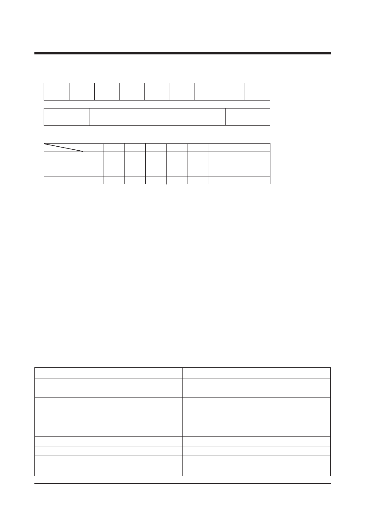
For Windows For Macintosh
PC with processor better than Pentium II 450MHz Power Mac G3 or later
(Pentium 700MHz recommended)
Windows 98/98SE/2000/ME/XP Mac OS 9.0~10.4
Minimum 64MB RAM
(XP : 128MB)
Minimum 64MB RAM
200MB of available hard disk space 110MB of available hard-disk space
(1GB recommended)
USB port USB port
CD-ROM drive CD-ROM drive
1024x768 pixels, 16bit color display compatible For playing back a movie clip
Mac OS 10.1 or later
monitor (24bit color display recommended) MPlayer, VCL Media Player
2. SYSTEM REQUIREMENTS
- Image Size
ĮNormal Shooting Mode
·Wide Shooting Mode
- Internal Capacity (23MB)
·Normal Shooting Mode
* These figures are measured under Samsung’s standard conditions and may vary depending on shooting conditions
and camera settings
■ Image Play
- Type : Single image, Thumbnails, Slide show, Movie Clip
- Editing :
Trimming, Resizing, Rotate, Color Effect
■ Interface
- HDMI (High Definition Multimedia Interface) Connection
- Digital output connector : USB 2.0 - Audio : Mono
- Video output : NTSC, PAL (user selectable)
- DC power input connector : 4.2V
■ Power Source
- Rechargeable battery : 3.7V Li-ion battery :SLB1237
- Charger: DC 4.2V, 750mA
- Cradle (Optional)
※ Included battery may vary depending on sales region.
■
Dimensions (WxHxD) : 109.2 x 64 x 29 mm (excluding protrusion)
■
Weight : 190g (without batteries and card)
■ Operating Temperature : 0 ~ 40°C
■ Operating Humidity : 5 ~ 85%
■ Software
-
Camera Driver : Storage Driver (2000/ ME/ XP, Mac OS 10.0 - 10.3)
-
Application : Digimax Master 1.0, Digimax Reader
※ Specifications are subject to change without prior notice.
※ All trademarks are the property of their respective owners.
8M 7M 6M 5M 4M 3M 2M 1M VGA
3264x2448 3072x2304 2816x2112 2592x1944 2272x1704 2048x1536 1600x1200 1024x768 640x480
5M 4M 3M 2M 1M
3264x1632 2816x1408 2272x1136 2048x1024 1600x800
8M 7M 6M 5M 4M 3M 2M 1M VGA
0011123820
44679122047102
891012 17 21 33 68 116
14 16 19 22 29 35 46 82 131
TIFF
Super Fine
Fine
Normal
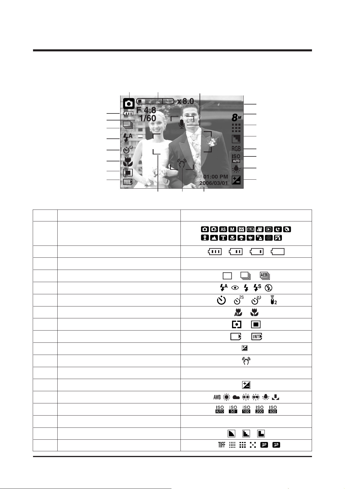
No. Descripition Icons
2 Battery
3Aperture Value / Shutter Speed F4.8, 1/60
4Continuous shot
5 Flash
6 Self-timer
7 Macro
8Metering
9 Card inserted indicator
10 Auto focus frame
11 Camera shake warning
12 Date / Time 2006/01/01 01:00 PM
13 Exposure compensation
14 White Balance
15 ISO
16 RGB RGB
17 Sharpness
18 Image quality / Frame rate
■ Recording mode
6
Ⅰ. SPECIFICATION
3. TFT LCD PANEL MARK
Recording mode
1
6
②
③
⑤
④
⑥
⑦
⑧
⑨
⑯
⑮
⑬
⑭
⑱
⑰
⑳
⑲
⑫⑩ ⑪
①
7
Ⅰ. SPECIFICATION
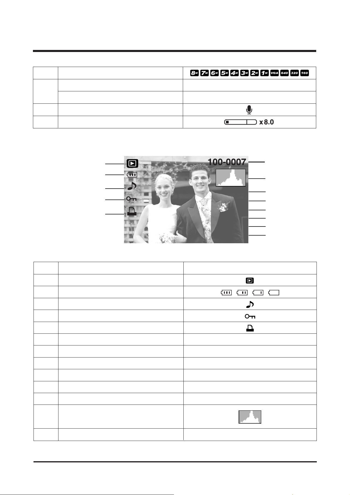
■ LCD monitor indicator
No. Descripition Icons
1 Play mode icon
2 Battery
3 Voice Memo
4 Protect
5 DPOF
6 Recording date 2006/03/01
7 Image size 3264X2448 ~ 256X192
8 Flash On / Off
9 ISO 50 ~ 400
10 Shutter speed 8 ~ 1/1,500
11 Aperture Value F2.8 ~ F13.8
13 Folder name & File name 100-0007
19 Image size
Number of available shots remaining 6
Remaining time (Movie clip/ Voice recording) 00:01:30/ 01:00:00
21 Voice memo
22 Optical/ Digital Zoom bar/ Digital Zoom rate
20
②
①
③
⑤
④
⑩
⑪
⑫
⑨
⑧
⑥
⑦
Av:F2.8
Tv:1/30
ISO:50
Flash:ON
3264X2448
2006/03/01
⑬
12
Histogram
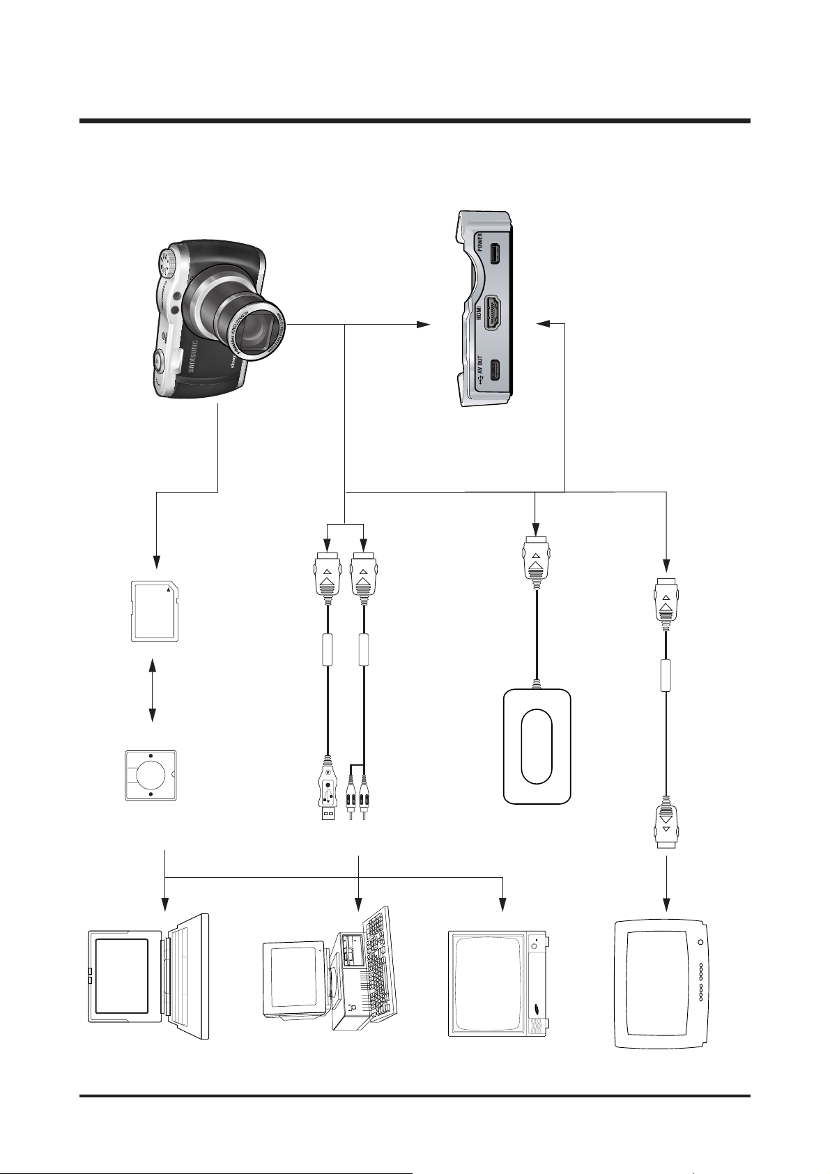
4. CONNECTION DIAGRAM
8
Ⅰ. SPECIFICATION
TV Monitor
IBM / MAC
Lap top
Card Reader SD Card
AC Adaptor
USB Cable
AV Cable
HDMI Cable
HDTV
9
Ⅰ. SPECIFICATION
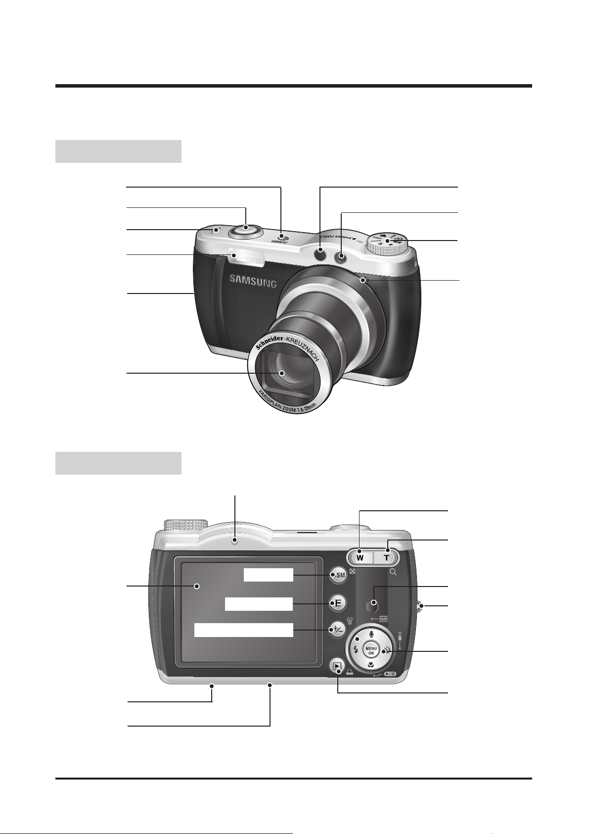
5. IDENTIFICATION OF FEATURES
Strap eyelet
Speaker
Shutter button
Remote control sensor
Mode dial
Microphone
Lens / Lens cover
LCD monitor
Tripod
5 function button
Play mode / Printer button
Zoom T button
(Digital zoom)
Camera status lamp
Zoom W button
(Thumbnail)
Front & Back
Back & Bottom
Power button
Strap eyelet
Self-timer lamp /
Auto focus lamp
E (Effect) button
ASM button
+/- button, Delete button
Remote control sensor
Camera strap eyelet
USB / AV connection
terminal
Cradle connector
10
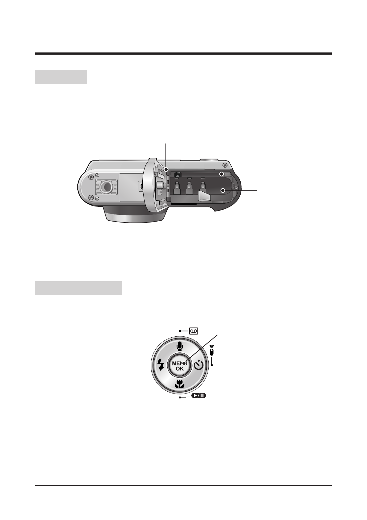
Ⅰ. SPECIFICATION
Battery chamber
Battery chamber cover
Memory card slot
Voice memo / Voice Recording / Up button
Flash /
Left button
Menu / OK button
Self-timer /
Right button
Macro / Down button
Play & Pause button
Bottom
5-function button
11
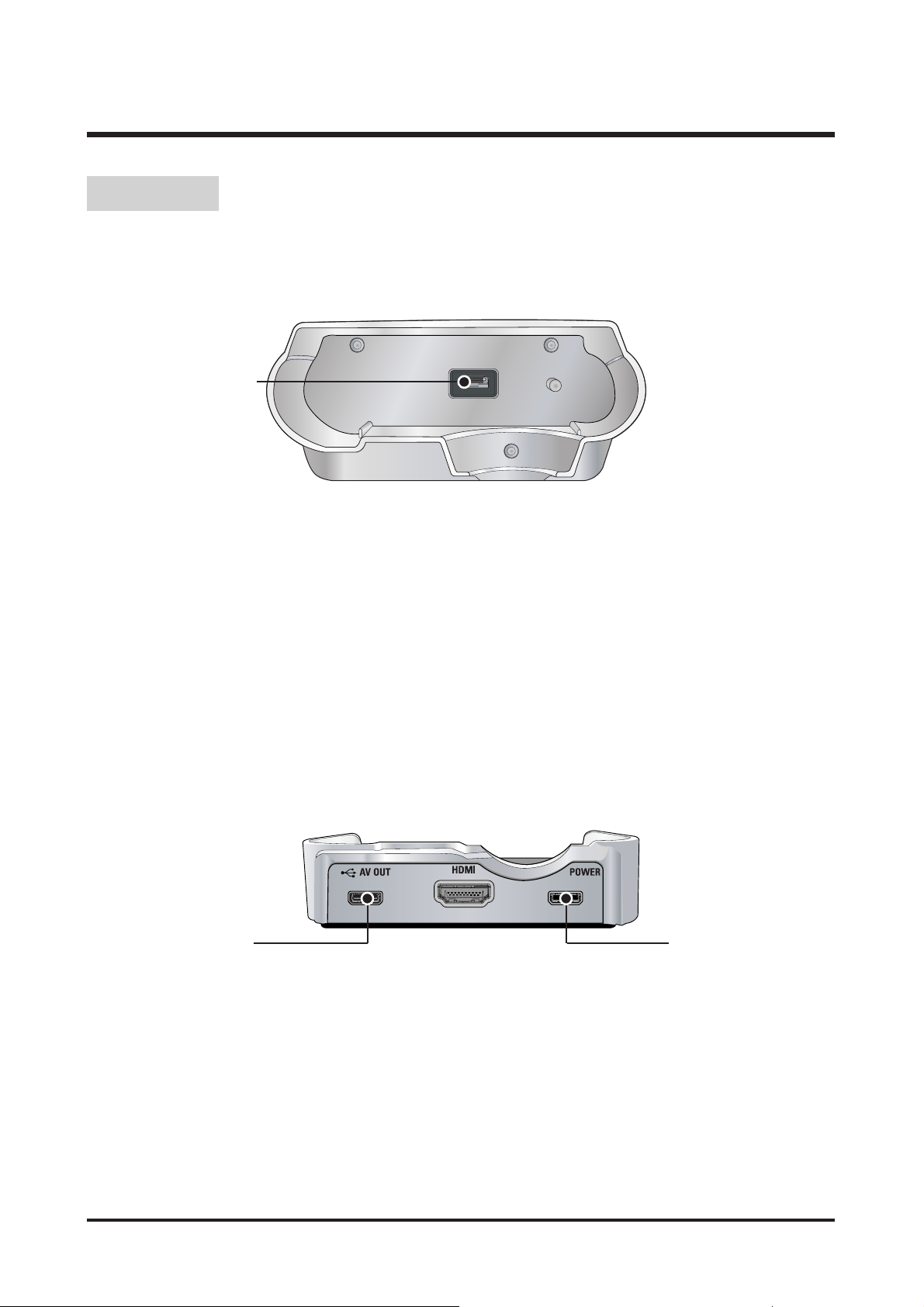
Ⅰ. SPECIFICATION
Camera
connection
terminal
AC connection
terminal
USB port /
AV connection terminal
● To p
● Back
Cradle
12
Ⅱ. INSTALLATION & FAQ
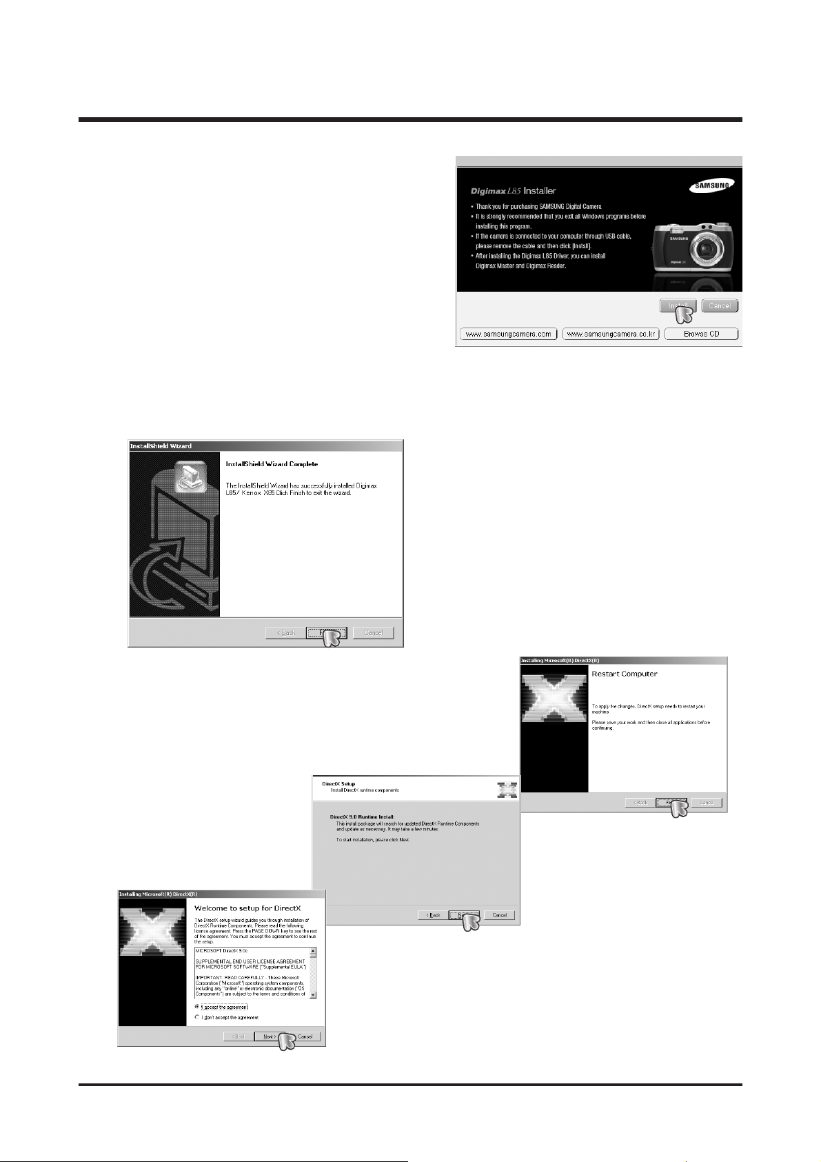
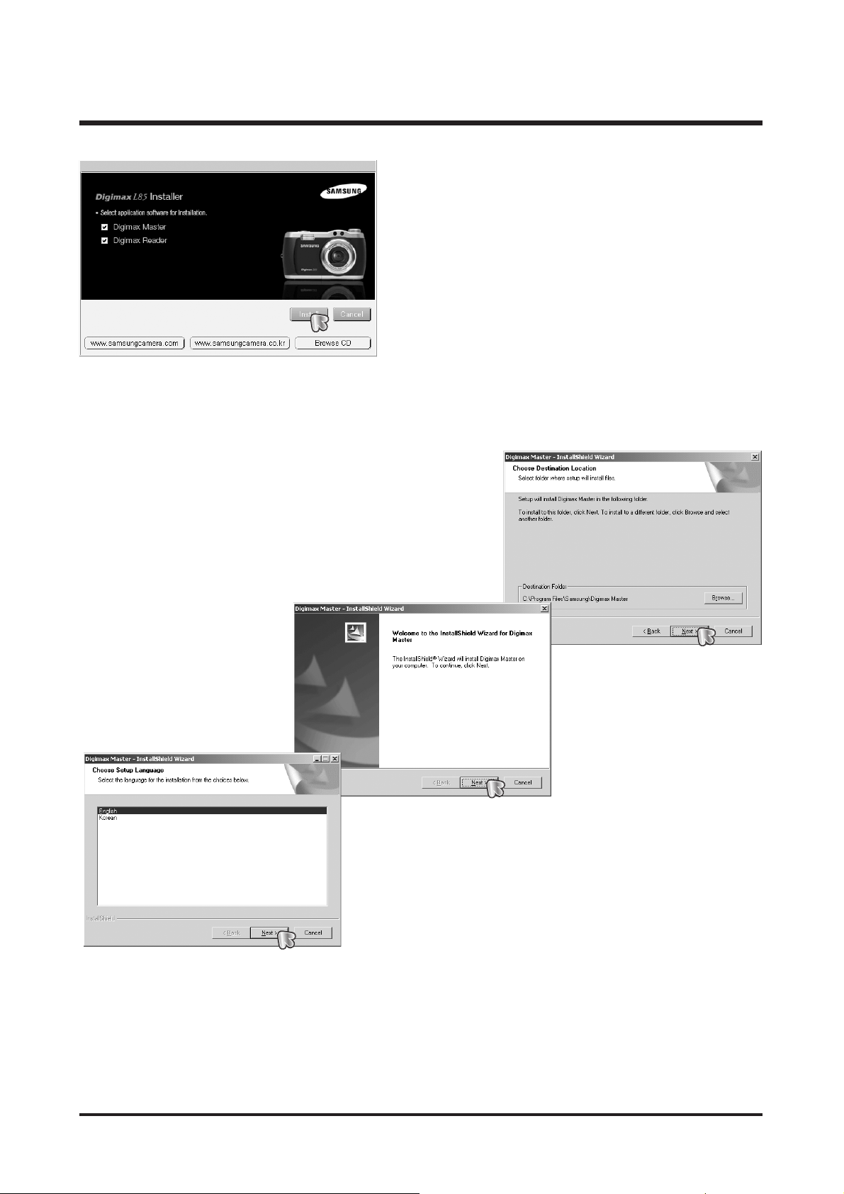
1. The auto run frame will display.
Click the [Install] menu in the Auto run frame.
2. Install the DirectX, Digimax Master by selecting a button shown on the monitor.
13
Ⅱ. INSTALLATION & FAQ
14
Ⅱ. INSTALLATION & FAQ

15
Ⅱ. INSTALLATION & FAQ
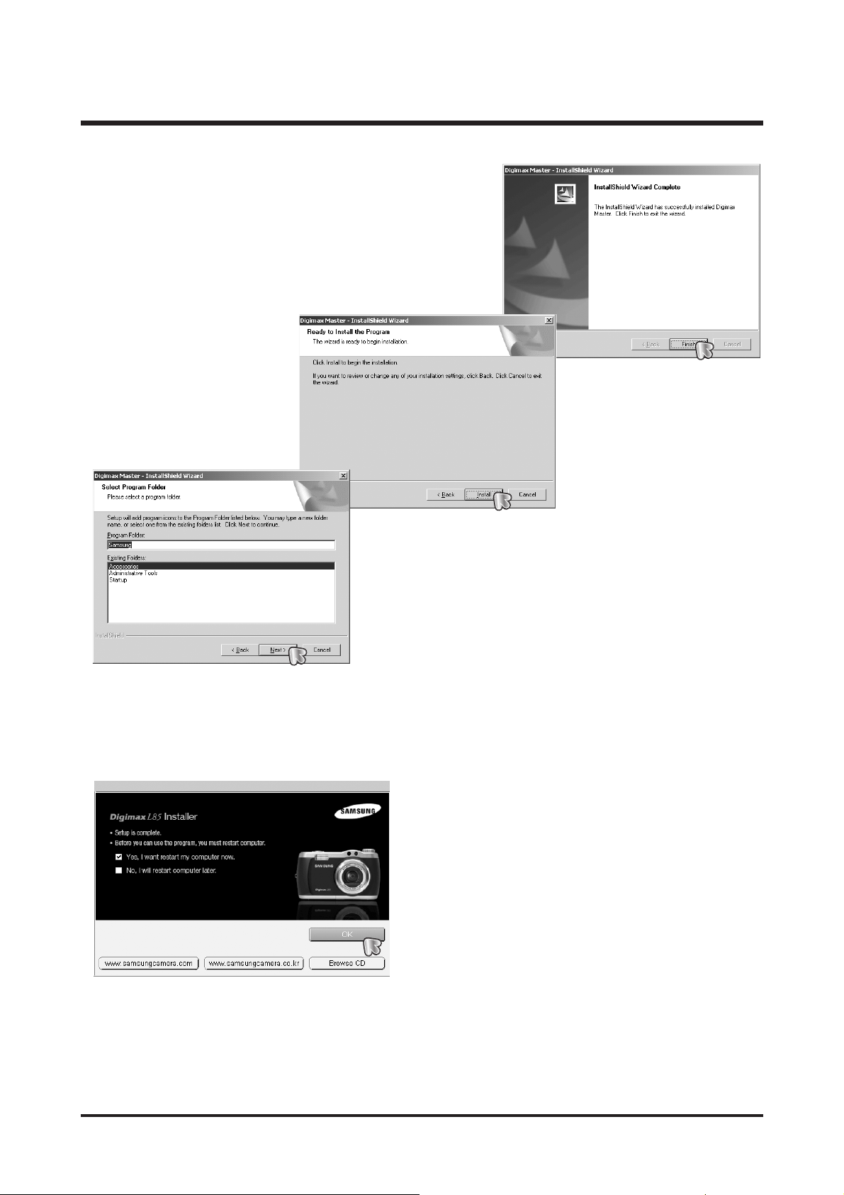
3. After restarting the computer, connect the PC to the camera with the USB cable.
● If you have installed the camera driver, The [Found New Hardware Wizard] may not open.
● On a Windows 98 or 98 SE system, the Found New Hardware Wizard dialog box opens and a window
asking you to select a driver file may appear. In this case, specify "USB Driver" in the CD supplied. (for
Windows 98 and 98 SE).
4. Turn the camera power on.
The [Found New Hardware Wizard] will open and the
computer will recognise the camera.
※ If your OS is Windows XP, an image viewer
program will open.
If the download window of Digmax Master opens
after starting Digimax Master, the camera driver
was set up successfully.

16
Ⅱ. INSTALLATION & FAQ
FAQ
<< For Windows >>
* System Requirements
- Windows 98/98SE, ME, 2000, XP
(Digimax Master can be installed and run in the Windows 98SE but that is not covered by Samsung's warranty)
- Pentium Ⅱ 450MHz or higher (Pentium 700MHz recommended)
- Minimum 200MB hard disk space (1GB recommended)
- Minimum 64MB RAM (128MB recommended)
- 1024X768 pixels, 16-bit colour display compatible monitor
- DirectX 9.0 or later
* Using a Hand-made PC or a PC and OS that has not been guaranteed by the manufacturer is not covered by the
Samsung warranty.
* When the supplied software is installed in the Windows 2000 or XP, log on as an Administrator account.
* If two or more USB devices are connected on a PC, some devices may not operate correctly.
* Connect the camera directly to the PC. Don't use the USB hub or USB located on the keyboard.
* The computer may not recognize the camera when the computer is resuming from the suspend or sleep mode.
* If there are delays when the movie plays back on the camera, copy the files on the computer and play them back
on the computer.
Q1. While the S/W installation, DirectX is inatalled. Do I have to install the program?
A1. To play back a Movie taken with S800 on the computer without any delay, you must install the program.
Click the Install button on the auto-run window and USB driver will be installed first and DirectX 9.0 is
installed.
On the Windows 98/98SE/ME, DirectX will installed automatically, on the Windows 2000/XP, your computer
checks the version of DirectX. If an old version of DirectX was installed on your compter, DirectX 9.0 will
install automatically. DirectX is a collection of applications for easily handling tasks related to multi-media and
game programs on the Microsoft Windows operation system. DirectX allows direct access 2D, 3D graphics,
sound, movie programs to hardware devices. So it is called 'DirectX'.
Q2. How can I check the version of installed DirectX?
A2. Click [Start → Run] and type 'DXdiag'. Click OK
button and a window for checking the DirectX will
display. You can check the version of installed
DirectX on the window.

17
Ⅱ. INSTALLATION & FAQ
< Note >
DirectX is required about 55MB hard disk space. It will take about 22MB hard disk space after
installing the DirectX. It will change settings of applications and registries. You can't remove it as the
OS doesn't have uninstall program.
Q3. My computer can't recognize the camera.
A3. (1) Install the supplied USB Driver.
(2) Check the USB cable connection between the compter and camera.
(3) The connected camera must be turned on. If the battery capacity is low, change it with fully charged one
or use the AC adapter.
(4) USB menu of the camera setting must be set as Computer. You can change the setting in the Setup
menu of the camera by using the 5 function button.
(5) If you connect the camera to the computer without installing the USB Driver, the compter may not
recognize the camera. In this case, remove the cable and install the USB drive first.
(6) If other USB cables are connected to the compter, remove them. Sometimes the devices crash each
other. Remove them and reboot the computer. And then check whether the computer can recognize the
camera.
(7) If the steps 1-6 are correct, remove the USB driver and install again.
Q4. How can I check whether the USB Driver was installed correctly?
A4. Install the USB Driver and connect the camera and the computer with the supplied USB cable. And then turn
them on. You can find the removeable disk.
(1) "The device is working properly" message will display on the system information window.
(2) The camera driver file has to be installed under the following folders.
< Windows 98/98SE >
L85.inf : Windows/inf
DSCPDR.pdr : Windows/system/iosubsys
DSCSYS.sys : Windows/system32/drivers
< Windows ME / 2000 / XP >
usbstor.sys : Windows/system32/drivers
usbstor.inf : Windows/inf

18
Ⅱ. INSTALLATION & FAQ
Q5. Removing the USB Mass Storage driver for Windows 98/98SE
A5. When you remove the USB drivr files for Windows 98/99SE manually, refer to the following steps.
(1) Click [Control Panel → Program Add/Remove] and remove the Digimax S800.
(2) Click [Start → Run].
(3) Type "regedit" to run the regedit program.
(4) Select "HKEY_LOCAL_MACHINE/Enum/SCSI/SAMSUNG_DIGITAL_CAMERA_" and delete the VID
:0839, PID:103F folders by pressing the DEL button.
(5) Select "HKEY_LOCAL_MACHINE/Enum/USB" folder and delete VID_0839&PID_103F folder by
pressing the DEL button.
(6) Select "HKEY_LOCAL_MACHIN/System/CurrentControlSet/Services/Class/hdc" folder.
Select each folders related with "L85.inf" and delete them by pressing the DEL button.
The registry structures of Window 2000/XP are different from other Operating Systems. You must check
the folder name before deleting the data. To delete the data, you must log on as administrator account.
Q6. Does L85 support USB 2.0?
A6. L85 supports full speed of USB 2.0.
19
Ⅱ. INSTALLATION & FAQ
▶ Digimax Master 1.0
Digimax Master : This is the all-in-on multi media software solution.
You can download, view, edit and save your digital images and movie clips clip with this
software.
1. Functions
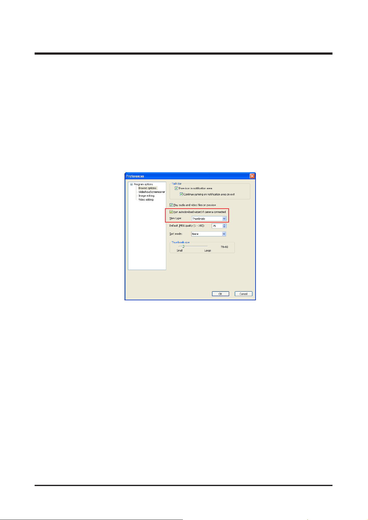
(1) AutoDownload : This program will download images captured with Samsung camera automatilcally.
- Click [File → Basic settings → Find Option] and then check the Auto download option
shown below.
(2) Viewer : You can view the stored images easily.
(3) Image edit : You can edit the still image.
(4) Movie edit : You can edit the movie and save it as *.avi, *.asf, *.wmv file type.
2. Essential codec
- Must be installed : DirectX 9.0 or later (Install separately)
- QuickTime 6.5 : This program is required for playing back the *.MOV type file. (Install separately)
3. I want send a mail with captured image. But E-mail icon is not activated.
- You did not set a default mail program. set the Microsoft Outlook Express as the default MAPI client.
20
Ⅲ. EXPLODED VIEW AND PART LIST
1-3
1-2
1-1
1-4
1-4
1-4
1-4
1-4
1-4
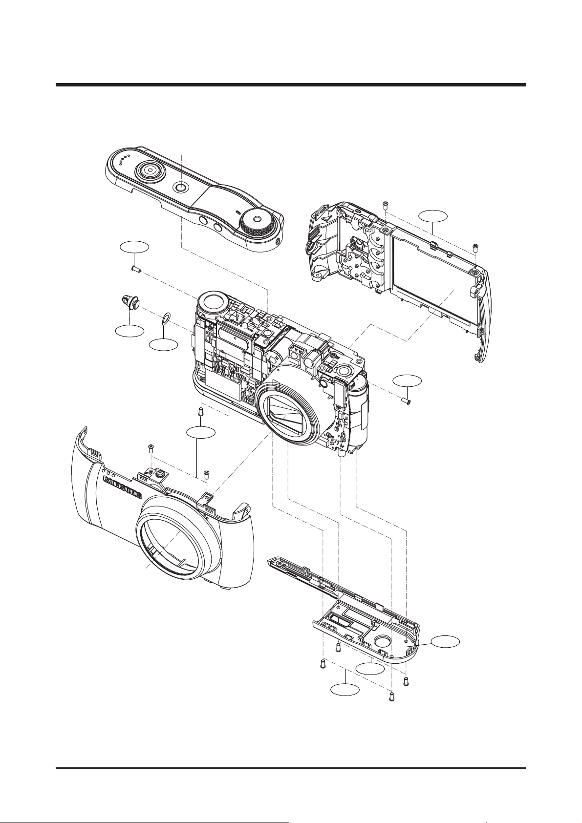
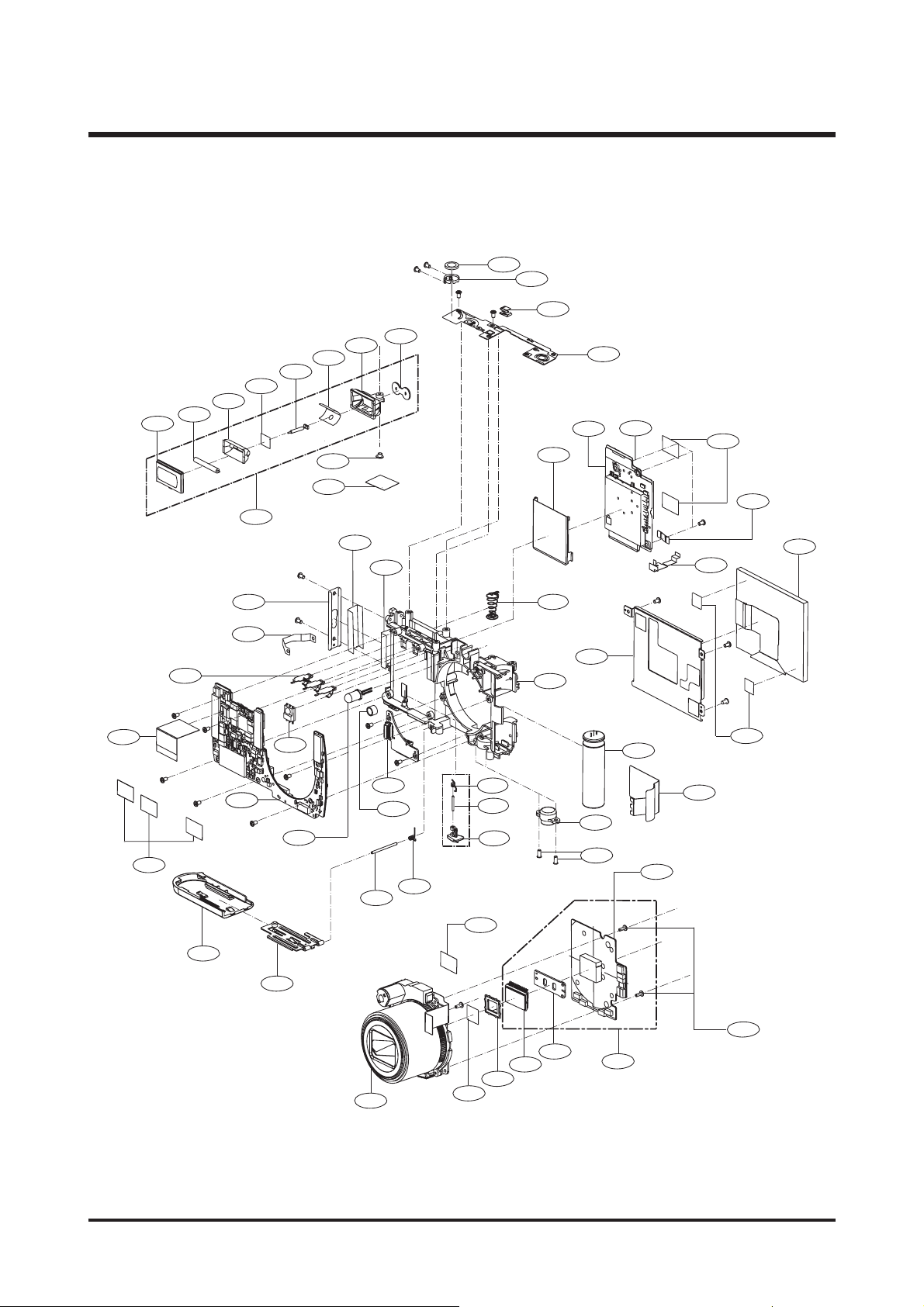
1. MAIN ASSEMBLY

21
Ⅲ. EXPLODED VIEW AND PART LIST
▶
PARTS LIST
1-1 Q7117016501A STRAP RING 1 O
1-2 Q6044002401A COPPER STRAP 1 O
1-3 Q7217390101A BOTTOM COVER 1 O
1-4 Q6003050101A SCREW 12 X
Fig.No Parts No. Parts Name Q’ty
Supply Available Parts
Remarks
22
Ⅲ. EXPLODED VIEW AND PART LIST
2-52-5
2-17 2-17
2-282-28
2-362-36
2-322-32
2-52-5
2-332-33
2-342-34
2-252-25
2-392-39
2-1 2-1
2-22-2
2-152-15
2-142-14
2-302-30
2-102-10
2-212-21
2-232-23
2-352-35
2-202-20
2-222-22
2-182-18
2-342-34
2-382-38
2-42-4
2-252-25
2-262-26
2-552-55
2-502-50
2-512-51
2-532-53
2-542-54
2-572-57
2-562-56
2-402-40
2-492-49
2-462-46
2-482-48
2-432-43
2-522-52
2-452-45
2-472-47
2-292-29
2-162-16
2-412-41
2-442-44
2-3 2-3
2-242-24
2-92-9
2-82-8
2-72-7
2-372-37
2-122-12
2-132-13
2-12-11
2-192-19
2-312-31
2-62-6
2-422-42
2. BODY ASSEMBLY

23
Ⅲ. EXPLODED VIEW AND PART LIST
▶
PARTS LIST
2-1 Q7204029501A CHASSIS 1 O
2-2 Q9002142801A TSOE N5 LENS 8M5X 1 O
2-3 Q2502891601A FLASH EC 1 O
2-4 Q9008104001A UI BD ASS'Y 1 O
2-5 Q9008104101A MAIN BD ASS'Y 1 O
2-6 Q9008104201A SMT ASS'Y CONNRCTOR BD 1 O
2-7 Q7204029601A BATTERY COVER 1 O
2-8 Q6107073201A BATTERY DOOR SPRING 1 O
2-9 Q6119397401A BATTERY DOOR SHAFT 1 O
2-10 Q7001009201A BATTERY COVER PLATE 1 O
2-11 Q7204029701A BATTERY LOCK 1 O
2-12 Q6107073301A BATTERY LOCK SPRING 1 O
2-13 Q6119397501A BATTERY LOCK SHAFT 1 O
2-14 Q6107073401A INSIDE BATTERY SPRING 3 O
2-15 Q7204029801A TRIPOT_SCREW 1 O
2-16 Q7204029901A SPEAKER HOLDER 1 O
2-17 Q7204030001A STRAP BRACKET 1 O
2-18 Q7004002301A LCD BRACKET 1 O
2-19 Q6107073501A BATTERY PUSH SPRING 1 O
2-20 Q7101002501A SD BRACKET 1 O
2-21 Q3708015501A CABLE FFC MAIN-UI 1 X
2-22 Q0109000501A LCD SPONGE 2 X
2-23 Q6002031301A SCREW 3 X
2-24 Q6002031401A SCREW 19 X
2-25 Q6002031501A SCREW 3 X
2-26 Q0704013001A LCD PANNEL 1 O
2-27 Q3708015301A CABLE FFC MAIN-SENSOR 1 O
2-28 Q3708015401A FFC ABSORBER 1 O
2-29 Q3001001401A SPEAKER 1 O
2-30 Q3003001501A MIC 1 O
2-31 Q0704013101A LED WITH WIRES 1 O
2-32 Q9008104301A IR RECEIVER MODULE 1 O
2-33 Q0203001201A MAIN NOISE COPPER 1 X
2-34 Q0203001301A INSULATION TAPE 6 X
2-35 Q9008104801A SENSOR BOARD ASS'Y 1 O
2-36 Q0109000601A COPPER MAIN BUTTON 1 X
2-37 Q0109000701A COPPER MAIN SENSOR 1 X
2-38 Q0109000801A COPPER SENSOR BUTTON 1 X
2-39 Q0109000901A COPPER SENSOR CONN 1 X
2-40 Q9008104701A FLASH SUB ASS'Y 1 O
2-41 Q9008104401A SMT ASS'Y-STROBE BD 1 O
2-42 Q0109001001A MYLAR_STROBE 1 X
2-43 Q6002031601A SCREW 1 X
2-44 Q6107073601A GND SPRING 1 X
2-45 Q7014010001A FLASH HOLDER 1 X
2-46 Q0611005601A FLASH TUBE BGAC 1 X
2-47 Q7309050401A FLASH-BAND 1 X
2-48 Q7014010101A REFLECTOR 1 X
2-49 Q7209005001A FLASH WINDOW 1 X
2-50 Q0210001601A COPPER FOIL 1 X
2-51 Q9008104501A TRIGGER WIRE WITH TRIGGER 1 X
2-52 Q0203001401A INSULATION TAPE 1 X
2-53 Q7309050501A OLPF RUBBER 1 O
2-54 Q6735004601A IR CUT 1 O
2-55 Q9008104601A SMT ASS'Y -SENSOR BD 1 X
2-56 Q7001009301A CCD METAL PLATE 1 X
2-57 Q0604006501A CCD SENSOR 1 X
Fig.No Parts No. Parts Name Q’ty
Supply Available Parts
Remarks
24
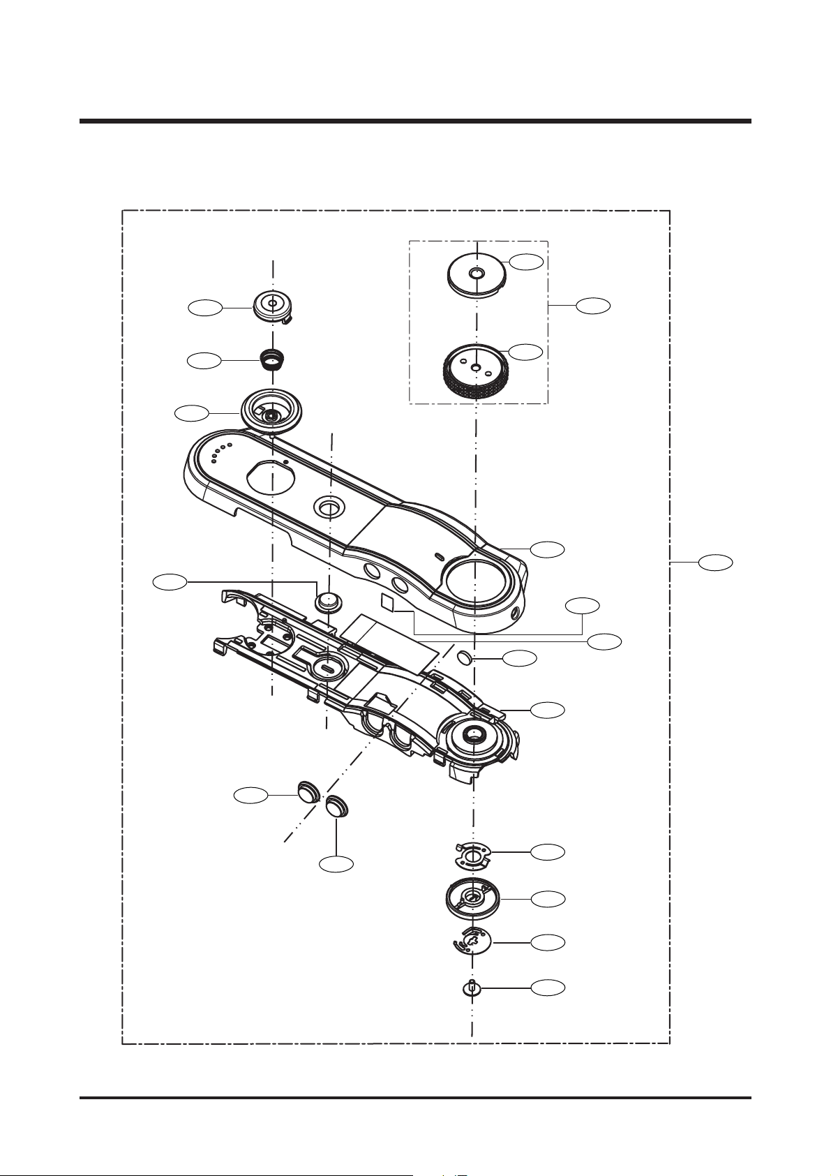
Ⅲ. EXPLODED VIEW AND PART LIST
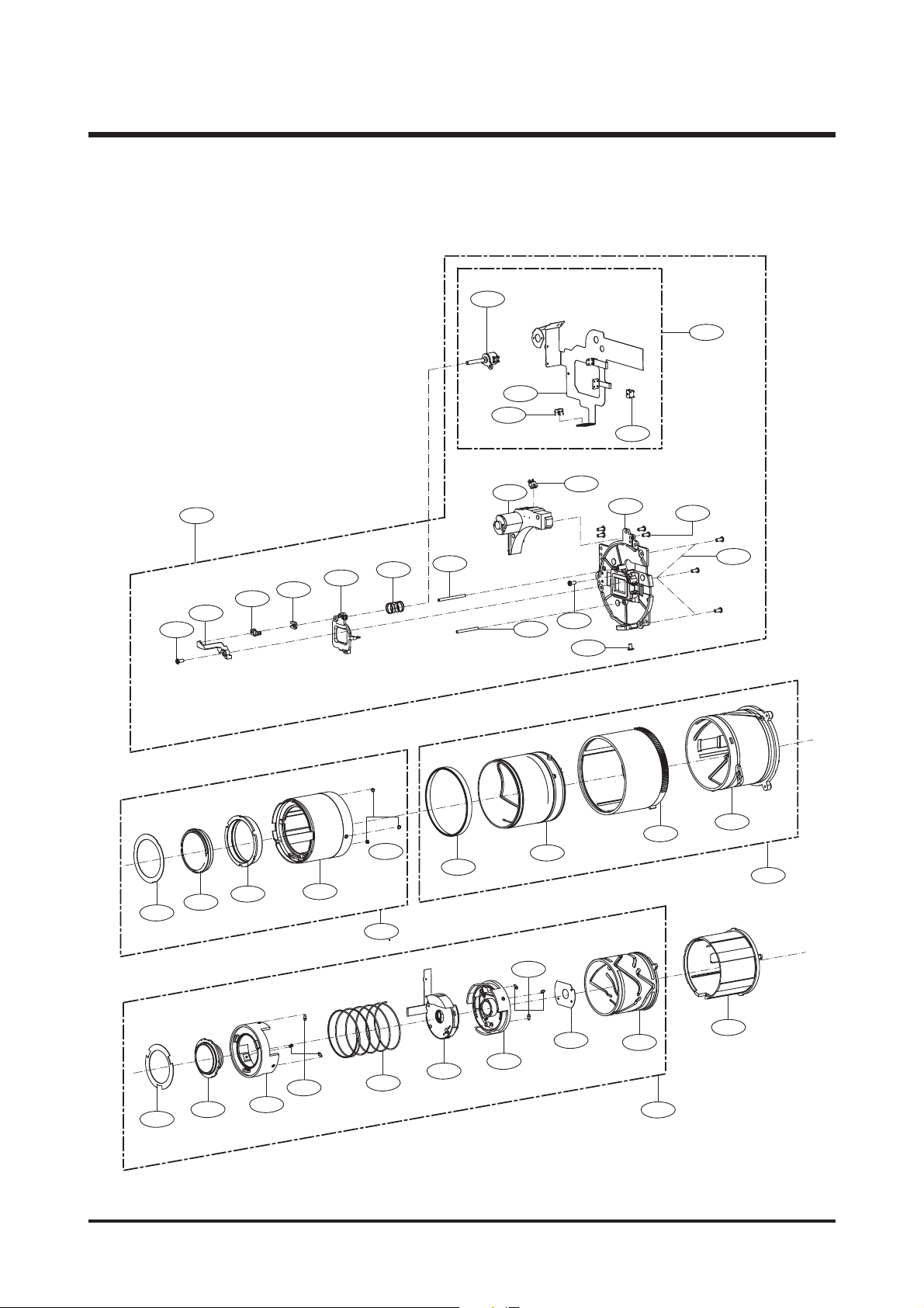
3. BARREL ASSEMBLY
3-1
3-4
3-2
3-6
3-5
3-21
3-7
3-44
3-8
3-22
3-9
3-23
3-10
3-11
3-25
3-12
3-26
3-41
3-13
3-24
3-15
3-14
3-27
3-3
3-13
3-19
3-16
3-28
3-17
3-20
3-29
3-42
3-30
3-31
3-32
3-33
3-34
3-35
3-36
3-33
3-38
3-39
3-40
3-43

25
Ⅲ. EXPLODED VIEW AND PART LIST
▶
PARTS LIST
3-1 Q9002145901A AF MOTOR
ASS'Y
1
X
3-2 Q4101034902A MAIN F-PCB
ASS'Y
1
X
3-3 Q0608001301A PHOTO INTERRUPTER SHARP 1
X
3-4 Q9008096801A MAIN F-PCB
ASS'Y
1
O
3-5 Q0608001001A PHOTO INTERRUPTER 1
X
3-6 Q0609000701A PHOTO REFLECTOR 1
X
3-7 Q0961900301A SCREW 1
X
3-8 Q7212192602A AF GUIDE HOLDER 1
O
3-9 Q7012080802A AF CLIP HOLDER 1
O
3-10 Q7012080702A AF CLIP 1
O
3-11 Q9002143201A 4TH BARREL
ASS'Y
1
O
3-12 Q6107066401A 4TH LENS SPRING 1
O
3-13 Q7411121802A AF GUIDE BAR - A 1
O
3-14 Q7411121901A AF GUIDE BAR - B 1
O
3-15 Q9002148802A ZOOM GEAR
ASS'Y
1
O
3-16 Q7212191303A LENS BASE 1
O
3-17 Q0961900301A SCREW 4
X
3-18 Q0961900301A SCREW 1
X
3-19 Q0994913101A SCREW 1
X
3-20 Q0961900301A SCREW 3
X
3-21 Q7409208602B 1ST SHIELD 1
X
3-22 Q9002142901A 1ST BARREL
ASS'Y
1
X
3-23 Q7212192101A SLIP RING 1
X
3-24 Q7212192101A CAM DECO RING 1
X
3-25 Q7212197501A ZOOM RING 1
X
3-26 Q7411110404A 1ST MOVE PIN 3
X
3-27 Q7212197401A CAM BARREL 1
X
3-28 Q9002147701A OUTER GUIDE BARREL 1
O
3-29 Q7212191503B OUTER CAM BARREL 1
O
3-30 Q7409208702B 2ND SHIELD 1
X
3-31 Q9002143001A 2ND BARREL
ASS'Y
1
X
3-32 Q7212192004A 2ND MOVE BARREL 1
X
3-33 Q7411121703A 2ND MOVE PIN 3
X
3-34 Q6107066102A 2ND LENS SPRING 1
X
3-35 Q9005163201A SHUTTER
ASS'Y
1
X
3-36 Q9002143101A 3RD BARREL
ASS'Y
1
X
3-37 Q7411121703A 2ND MOVE PIN 3
X
3-38 Q7012088701A 3RD LIGHT SHIELD 1
X
3-39 Q7212191901A INNER CAM BARREL 1
X
3-40 Q7212191801B GUIDE BARREL 1
O
3-41 Q9002148501A ZOOM RING
ASS'Y
1
O
3-42 Q9002148201A CAM BARREL
ASS'Y
1
O
3-43 Q9002148101A INNER CAM BARREL
ASS'Y
1
O
3-44 Q9002146101A LENS BASE
ASS'Y
1
O
Fig.No Parts No. Parts Name Q’ty
Supply Available Parts
Remarks
26
Ⅲ. EXPLODED VIEW AND PART LIST
4-9
4-6
4-5
4-4
4-2
4-1
4-2
4-3
4-4
4-5
4-7
4-8
4-10
4-11
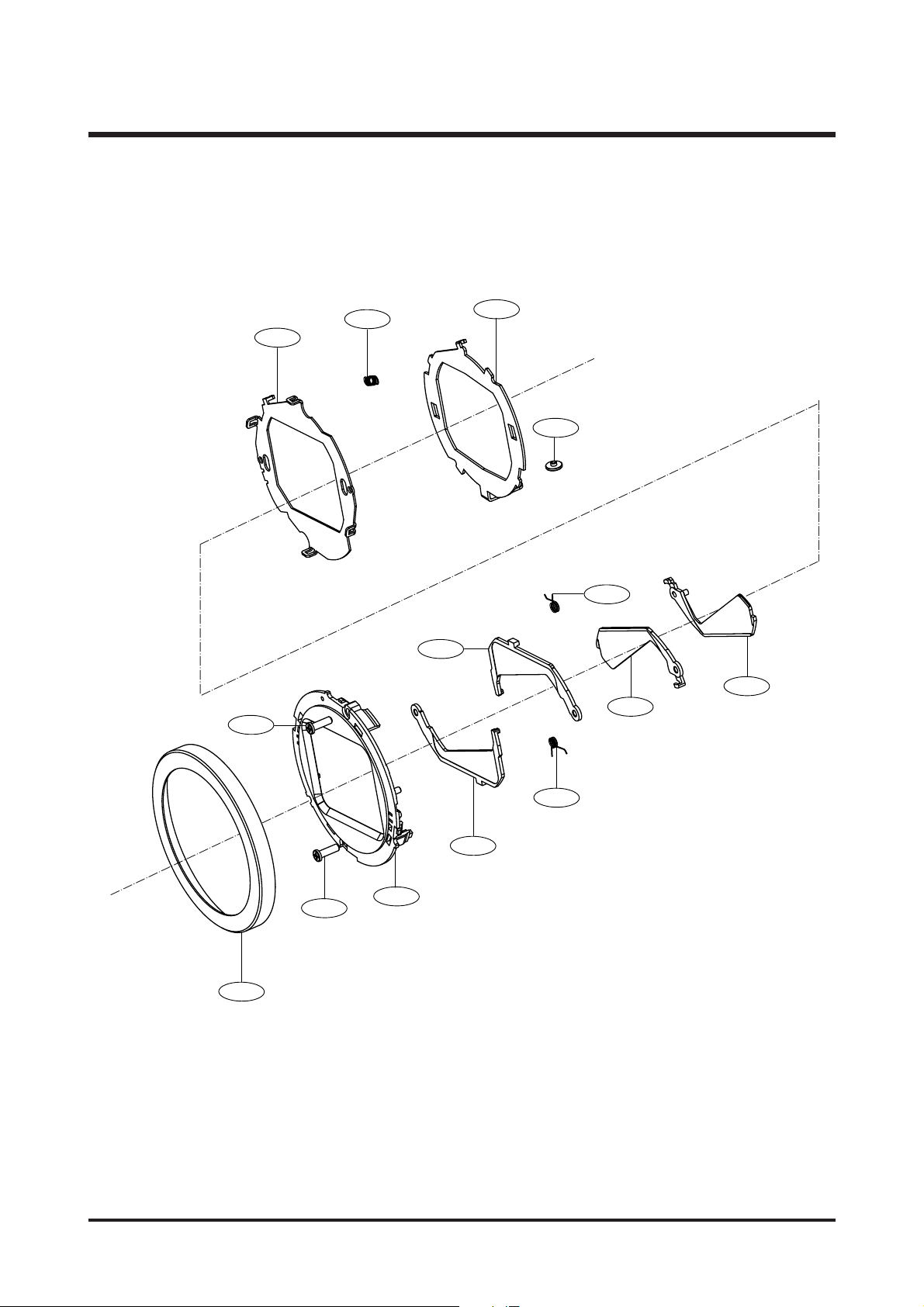
4. BARRIER ASSEMBLY

27
Ⅲ. EXPLODED VIEW AND PART LIST
▶
PARTS LIST
4-1 Q7012092101A DECORATION RING 1 O
4-2 Q6003048701A BARRIER SCREW-A 2
X
4-3 Q7212192805A FRONT PANEL 1 O
4-4 Q7212193102A BARRIER C 2 O
4-5 Q6107066301A BARRIER CLOSE SPRING 2 O
4-6 Q7212192902A BARRIER A 1 O
4-7 Q7212193002A BARRIER B 1 O
4-8 Q7012087703B BARRIER BASE 1 O
4-9 Q6107066201A BARRIER OPEN SPRING 1 O
4-10 Q7012087802A BARRIER LEVER 1 O
4-11 Q7411122503A BARRIER LEVER PIN 1
X
Fig.No Parts No. Parts Name Q’ty
Supply Available Parts
Remarks
28
Ⅲ. EXPLODED VIEW AND PART LIST
5-2
5-3
5-4
5-1
5-5
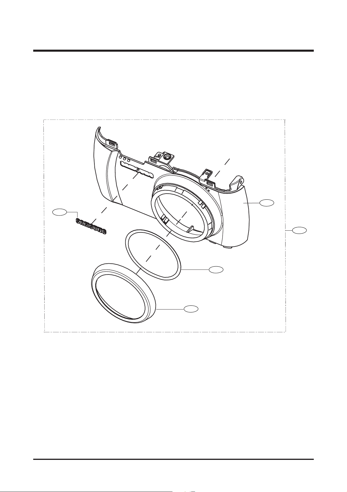
5. FRONT COVER ASSEMBLY

29
Ⅲ. EXPLODED VIEW AND PART LIST
▶
PARTS LIST
5-1 Q7217389201A FRONT COVER 1
X
5-2 Q7209005101A SAMSUNG-BADGE 1
X
5-3 Q7104000601A LENS COSMATIC RING 1
X
5-4 Q0203001501A LIGHT LEAKAGE MYLAR 1
X
5-5 Q9007268201A FRONT COVER ASS'Y-DIGIMAX 1 O
Q7217390301A FRONT COVER ASS'Y-KENOX 1 O
Fig.No Parts No. Parts Name Q’ty
Supply Available Parts
Remarks
30
Ⅲ. EXPLODED VIEW AND PART LIST
6-5
6-7
6-6
6-4
6-15
6-14
6-17
6-12
6-10
6-11
6-3
6-16
6-19
6-2
6-9
6-13
6-8
6-18
6-1
6. TOP COVER ASSEMBLY
 Loading...