

Page 1

Page 2

2
CONTENTS
Ⅰ.SPECIFICATION
1.CAMERASPECIFICATION ……………………………………………………………………………………… 4
2.SYSTEMREQUIREMENTS ……………………………………………………………………………………… 6
3.TFTLCDPANELMARK ……………………………………………………………………………………… 7
4.CONNECTIONDIAGRAM ……………………………………………………………………………………… 9
5.IDENTIFICATIONOFFEATURES ……………………………………………………………………………… 10
Ⅱ.INSTALLATION&FAQ
……………………………………………………………………………………… 13
Ⅲ.EXPLODEDVIEWANDPARTSLIST
1.MAINASSEMBLY ………………………………………………………………………………………………22
2.BODYASSEMBLY ………………………………………………………………………………………………24
3.BARRELASSEMBLY…………………………………………………………………………………………… 28
4.FRONTCOVERASSEMBLY ……………………………………………………………………………………30
5.MIDDLECOVERASSEMBLY……………………………………………………………………………………32
6.BACKCOVERASSEMBLY………………………………………………………………………………………34
7.CRADLEASSEMBLY ……………………………………………………………………………………………36
8.PACKINGITEM …………………………………………………………………………………………………38
Ⅳ.ADJUSTMENT
1.Digitalcameraservice …………………………………………………………………………………………42
2.Adjustmentitemsbychangedparts …………………………………………………………………………48
3.Adjustment ………………………………………………………………………………………………………51
(1)Adjustmentbychangedpart ……………………………………………………………………………52
(2)EEPROMCOPY ……………………………………………………………………………………………63
Ⅴ.PATTERNDIAGRAM
1.PARTSARRANGEMENTFOREACHPCBASS’Y
1)MAIN_TOP …………………………………………………………………………………………………64
2)MAIN_BOTTOM ……………………………………………………………………………………………65
3)SUBPCB_TOP………………………………………………………………………………………………66
4)SUBPCB_BOTTOM ………………………………………………………………………………………67
5)CARDFPCB …………………………………………………………………………………………………68
6)STROBO ………………………………………………………………………………………………………69
7)CCD……………………………………………………………………………………………………………69
Page 3

3
Ⅵ.CIRCUITDIAGRAM
1.BLOCKDIAGRAM ………………………………………………………………………………………………70
2.CIRCUITDIAGRAM
1)MAINBLOCKDIAGRAM ……………………………………………………………………………………71
2)MAIN_CAOCH ………………………………………………………………………………………………72
3)MAIN_FEP …………………………………………………………………………………………………73
4)MAIN_MEMORY ……………………………………………………………………………………………74
5)MAIN_MOTERDRIVER ……………………………………………………………………………………75
6)MAIN_uCOM ………………………………………………………………………………………………76
7)POWER ………………………………………………………………………………………………………77
8)CARD_FPCB…………………………………………………………………………………………………78
9)POWERONKEY ……………………………………………………………………………………………79
10)LCD …………………………………………………………………………………………………………80
11)STROBO ……………………………………………………………………………………………………81
12)AUDIO ………………………………………………………………………………………………………82
13)CARD ………………………………………………………………………………………………………83
14)TOPFPCB …………………………………………………………………………………………………84
15)STROBO ……………………………………………………………………………………………………85
16)CRADLE ……………………………………………………………………………………………………86
Ⅶ.TROUBLESHOOTING
1.CheckListforrepairing ………………………………………………………………………………………87
2.Principaltroubleshooting ………………………………………………………………………………………88
Ⅷ.SERVICEINFORMATION
1.Theorderofdisassemblyandassembly …………………………………………………………………111
Page 4

4
Ⅰ.SPECIFICATION
1. CAMERA SPECIFICATION
■ Image Sensor
- Type : 1/2.5" CCD
- Effective Pixel : Approx. 6.0 Mega-pixel - Total Pixel : Approx. 6.1 Mega-pixel
■ Lens
- Focal Length : SHD Lens f = 6.6 ~ 19.8mm (35mm film equivalent : 39 ~ 117mm)
- F No. : F 3.5 ~ F 4.5
- Digital Zoom :ㆍStill Image mode : 1.0X ~ 5.0X
ㆍPlay mode : 1.0X ~ 11.0X (depends on image size)
■ LCD Monitor : 2.5" Color TFT LCD
■ Focusing
- Type : TTL auto focus
- Range
■ Shutter
- Type : Mechanical and Electronic shutter
- Speed : 1 ~ 1/2,000 sec. (Night : 16 ~ 1/2,000 sec.)
■ Exposure
- Control : Program AE, Metering : Multi, Spot
- Compensation : ±2EV (0.5EV steps)
- ISO Equivalent : Auto, 50, 100, 200, 400
■ Flash
- Modes : Auto, Auto & Red-eye reduction, Fill-in flash, Slow sync, Flash off, Red-eye reduction
- Range : Wide : 0.2m ~ 2.4m, Tele : 0.3m ~ 1.9m (ISO Auto)
- Recharging Time : Approx. 4 sec.
■ Sharpness : Soft, Normal, Vivid
■ Effect : Normal, B&W, Sepia, Negative, Red, Green, Blue, RGB
■ White Balance : Auto, Daylight, Cloudy, Fluorescent_H, Fluorescent_L, Tungsten, Custom
■ Voice Recording : Voice Recording (max 1 hour), Voice Memo in Still Image (max. 10 sec.)
■ Date Imprinting : Date, Date&Time, Off (user selectable)
■ Shooting
- Still Image : ㆍModes : Auto, Program, Scene, ASR
※ Scene : Night, Portrait, Children, Landscape, Text, Close-up, Sunset, Dawn, Backlight,
Fireworks, Beach & Snow
ㆍShooting : Single, Continuous
ㆍSelf-timer : 2 sec., 10 sec., Double(10 sec., 2 sec.)
- Movie Clip : With Audio (recording time : Depend on Storage size)
Size : 640x480, 320x240, 160x128
Frame rate : 30 fps, 15 fps
Movie Stabilizer (User Selectable)
Movie Editing (Embeded) : Pause during recording, Still Image Capture, Time Trimming
■ Storage
- Media : Internal memory: About 45MB
Normal Macro Super Macro Auto Macro
5 ~ 50cm 1cm ~ 5cm 5cm ~ Infinity
25 ~ 50cm - 50cm ~ Infinity
50cm ~ infinity
Wide
Tele
Page 5

5
Ⅰ.SPECIFICATION
External memory: SD card /MMC (Up to 1GB Guaranteed)
*Internal memory capacity is subject to change without prior notice.
- File Format : Still Image : JPEG (DCF), EXIF 2.2, DPOF 1.1, PictBridge 1.0
Movie Clip : AVI (MPEG-4) Audio : WAV
- Image Size
- Capacity (64MB)
※ These figures are measured under Samsung’s standard conditions and may vary depending on shooting
conditions and camera settings.
■ Image Play
- Type : Single image, Thumbnails, Slide show(with Audio), Movie Clip
- Editing : Trimming, Resizing, Rotate, Effect
■ Interface : Digital output connector : USB 2.0 Audio : Mono
Video output : NTSC, PAL (user selectable)
DC power input connector : 24pin Connector
■ Power Source : Rechargeable battery : SLB-0837 (860mAh)
Adaptor : SAC-42
Optional Cradle
※ Included battery type may vary depending on sales region.
■ Dimensions (WxHxD) : 96x61x18.5mm
■ Weight : 129.5g
- Operating Temperature : 0 ~ 40℃ - Operating Humidity : 5 ~ 85%
■ Software
- Camera Driver : Storage Driver (Windows98/98SE/2000/ME/XP, Mac OS 9.0 ~ 10.4)
- Application : Digimax Master, Digimax Converter*, Digimax Reader
* OS : Windows 98SE/2000/ME/XP
(Windows 2000/XP recommended)
PC with processor better than Pentium III 500MHz
(Pentium Ⅳ recommended)
■ Special Features
- PMP Player Function Digimax Converter S/W (No Direct Playing)
MP3 Player Function, Red-eye Correction
ASR (Advanced Shake Reduction)
3X Optical Zoom for Still & Movie.
New Charging System (Cradle (Optional))
MPEG-4 VGA 30fps Movie Clip (supporting Edit on DSC)
Powerful Effect (Colour, Highlight, Composite, Frame)
Easy Mode Change using “M” button
6M 5M 4M 3M 2M 1M VGA
2816x2112 2592x1944 2272x1704 2048x1536 1600x1200 1024x768 640x480
6M 5M 4M 3M 2M 1M VGA
18 22 27 35 57 139 289
35 42 54 65 101 197 341
52 61 79 93 139 250 417
Super Fine
Fine
Normal
Page 6

6
Ⅰ.SPECIFICATION
2. System Requirements
※※
MP3 Specification
■ Audio
- Frequency : 20Hz ~ 20KHz
- Earphone Port : 3.5mm Port (Stereo Type)
- Output : Maximum Volume Left 15mW + Right 15mW(16Ω)
- Noise Ratio : 86 dB with 20 KHz LPF
■ File
- File Format : MP3 (MPEG-1/2/2.5 Layer 3)
- Bit Rate : 48 ~ 320kbps (Including VBR)
■ Play Mode : All, Repeat One, Repeat All, Random, Random Repeat
Skipping in Play, Auto Skipping
Slide Show On/Off (User Selectable),
MP3&Capturing (Capturing Mode is Auto Default, 3M)
Auto reload function (Remember last played file)
Background skin of MP3 playback using user images
※※
PMP Specification
■ PMP Decoder
- Movie : Xvid MPEG4 (Using Digimax Converter S/W)
- Audio : MPEG1 Layer 2 (Using Digimax Converter S/W)
■ Play Mode
- Seeking in Play (Max 32X), Skipping in Play,
- Auto skipping after one file played
- Auto reload function (Remember last played frame)
- Support Full Screen in Converting S/W
■ Subtitle : Support SMI file (Using Digimax Converter S/W)
For Windows For Macintosh
PC with processor better than Pentium II 450MHz
(Pentium 700MHz recommended)
Windows 98/98SE/2000/ME/XP
Minimum 128MB RAM
300MB of available hard disk space
1024x768 pixels, 16-bit colour display compatible
monitor (24-bit colour display recommended)
Digimax Converter
PC with processor better than Pentium III 500MHz
(Pentium Ⅳ recommended)
Windows 98SE/2000/ME/XP (Windows 2000/XP
recommended)
For playing back a movie clip
Mac OS 10.1~10.4
MPlayer, VCL Media Player
Power Mac G3 or later
Mac OS 9.0 ~ 10.4
Minimum 64MB RAM
110MB of available hard-disk space
Page 7
7
Ⅰ.SPECIFICATION
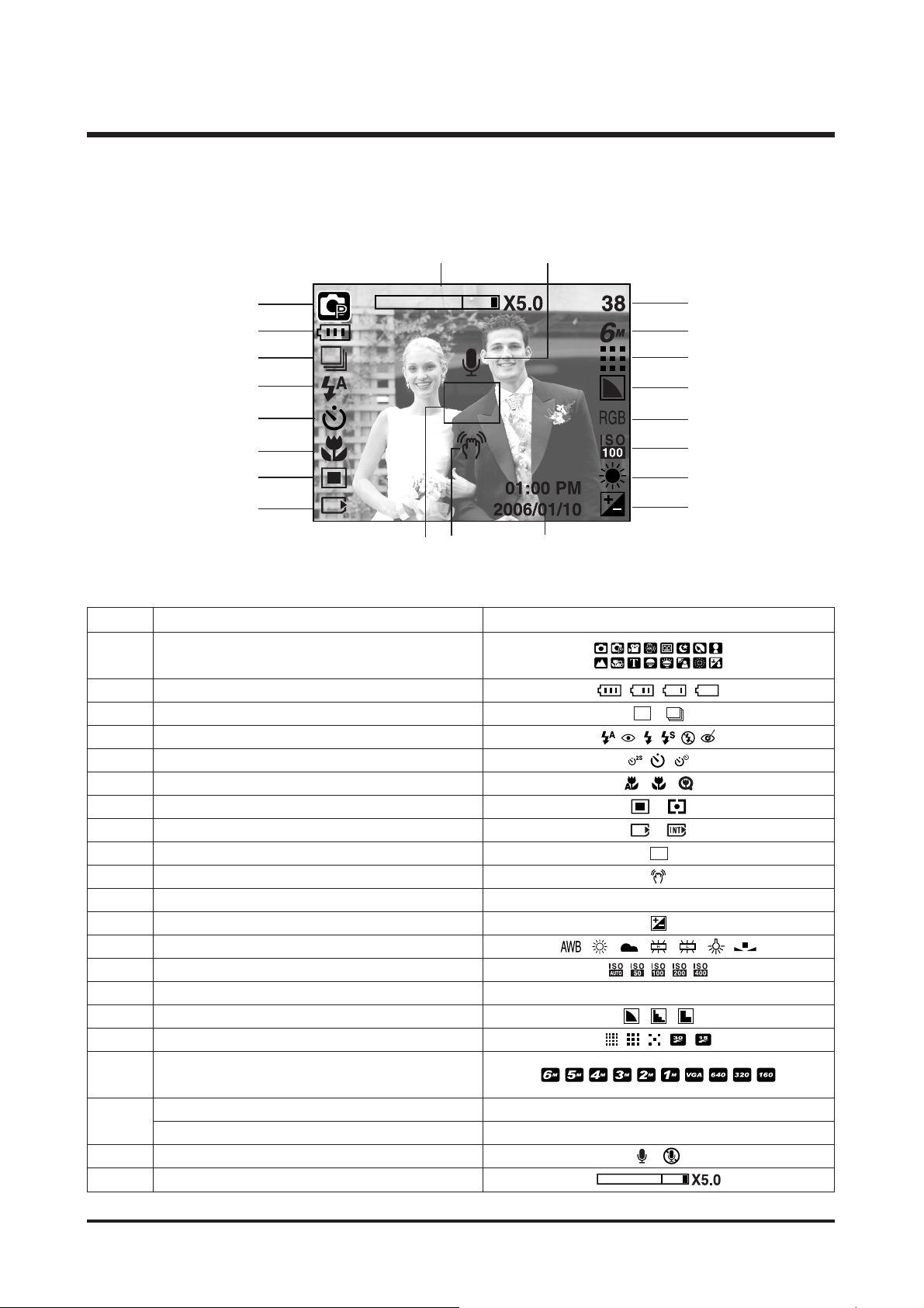
■ Recording mode
3. TFT LCD PANEL MARK
No. Description Icons
2 Battery
3 Continuous shot
4 Flash
5 Self-timer
6 Macro
7 Metering
8 Card inserted indicator
9 Auto focus frame
10 Camera shake warning
11 Date/ Time 2006/01/01 01:00 PM
12 Exposure compensation
13 White Balance
14 ISO
15 RGB RGB
16 Sharpness
17 Image quality/ Frame rate
Number of available shots remaining 38
Remaining time (Movie clip/ Voice recording) 00:01:30/ 01:00:00
20 Voice memo/ Mic. off
21 Optical/ Digital Zoom bar/ Digital Zoom rate
Recordingmode
1
19
18
①
②
③
④
⑤
⑥
⑦
⑧
⑬
⑫
⑭
⑮
⑰
⑯
⑱
⑲
⑩⑨
⑪
⑳
Image size
Page 8
8
Ⅰ.SPECIFICATION
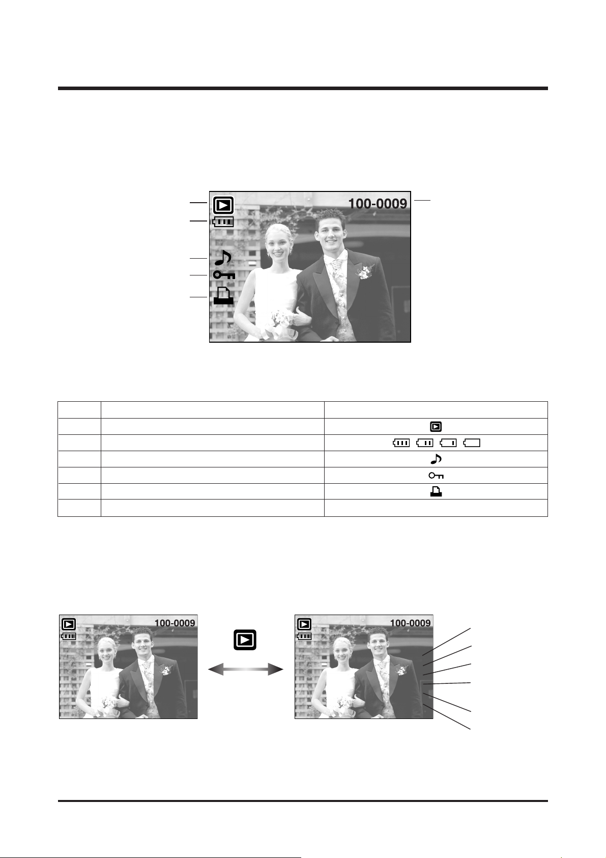
■ LCD monitor indicator
No. Description Icons
1 Play mode
2 Battery
3Voice Memo
4 Protect indicator
5 DPOF indicator
6 Folder name and Stored image number 100-0009
⑥
②
①
③
④
⑤
ISO sensitivity
Aperture value
Shutter speed
Whether or not the
flash is used
Size
Recording date
[Play mode display]
[Recording information]
Pressing for over 1 Sec.
ISO : 149
Av : F3.5
Tv : 1/60
Flash : Off
2816X2112
2006/01/10
Page 9
9
Ⅰ.SPECIFICATION
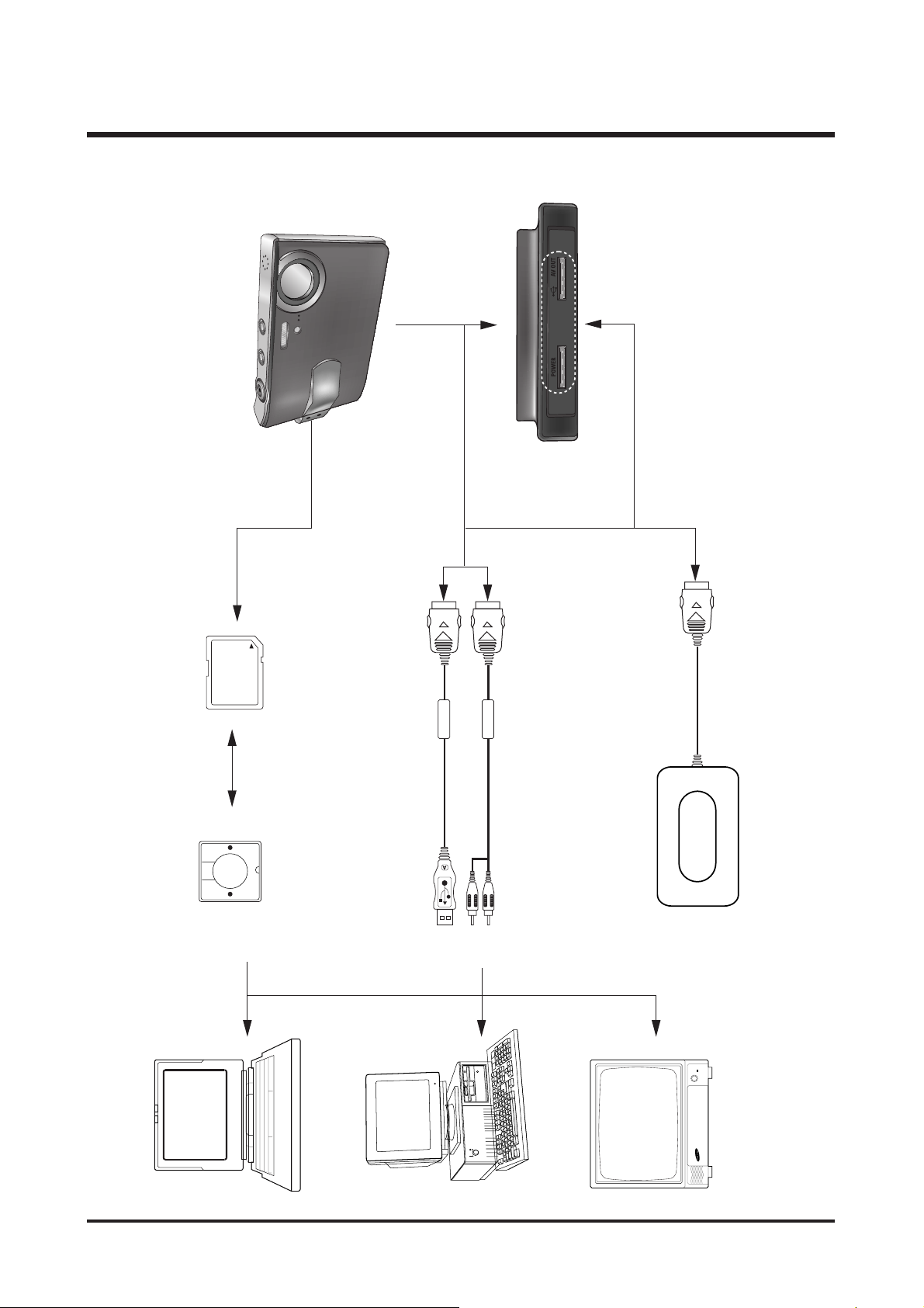
4. CONNECTION DIAGRAM
TV Monitor
IBM / MAC
Lap top
Card Reader SD Card
AC Adaptor
USB Cable
AV Cable
Page 10
10
Ⅰ.SPECIFICATION
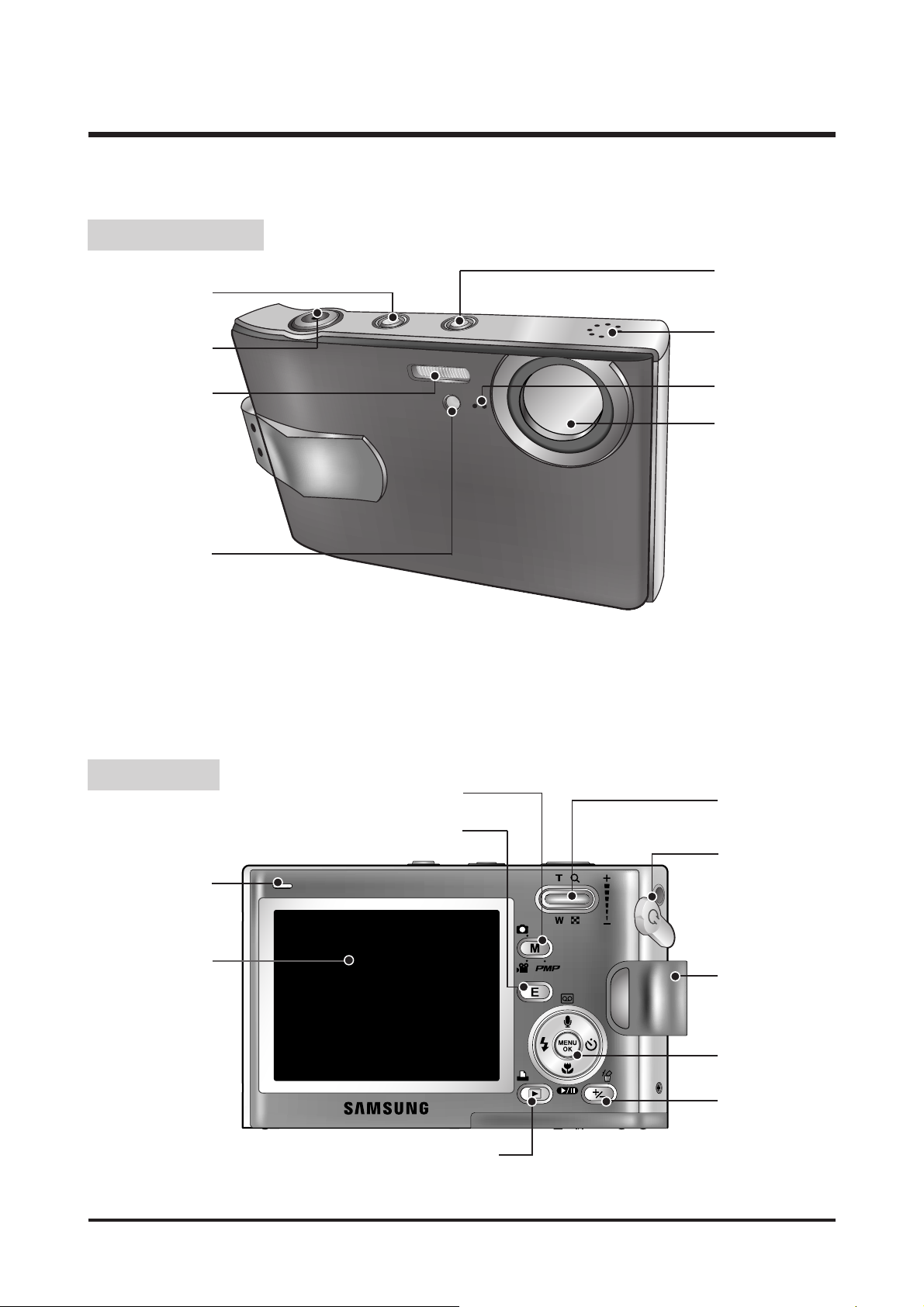
5. IDENTIFICATION OF FEATURES
Front & Top
Back
Power button
Flash
Optical 3X zoom
lens/ Lens cover
ASR mode button/
Hold button
Speaker
Microphone
Shutter button
Self-timer lamp/
Auto Focus lamp
LCD monitor
Play mode button/ Printer button
M(Mode) button
E (Effect) button
Earphones Jack
Camera strap
Camera status lamp
Zoom/ Thumbnail/
Volume button
5 function button
+/- button,
DELETE button
Page 11
11
Ⅰ.SPECIFICATION
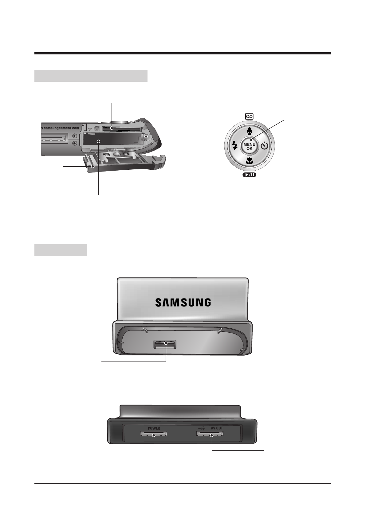
● Back
● Top
Battery holder
Memory card slot
Battery chamber
Battery chamber cover
FLASH/
LEFT button
MENU/ OK button
Macro/ DOWN button,
Play & Pause button
SELF-TIMER/
RIGHT button
Voice memo / Voice Recording / UP button
Camera connection
terminal
USB port
AV connection terminal
DC connection terminal
Bottom/ 5-function button
Cradle
Page 12
12
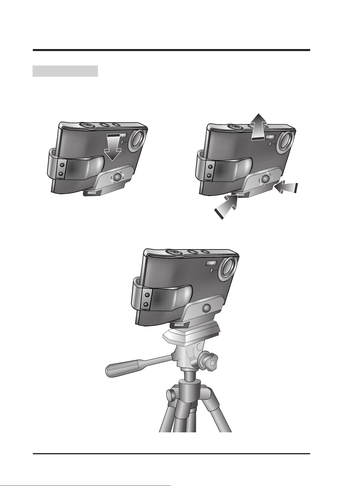
Ⅰ.SPECIFICATION
■ You can attach the camera on a tripod with this adaptor.
● Attaching the camera
● Removing the camera
①①
①①
②②
②②
③③
②②
Tripod Adaptor
Page 13
13
Ⅱ.INSTALLATION&FAQ
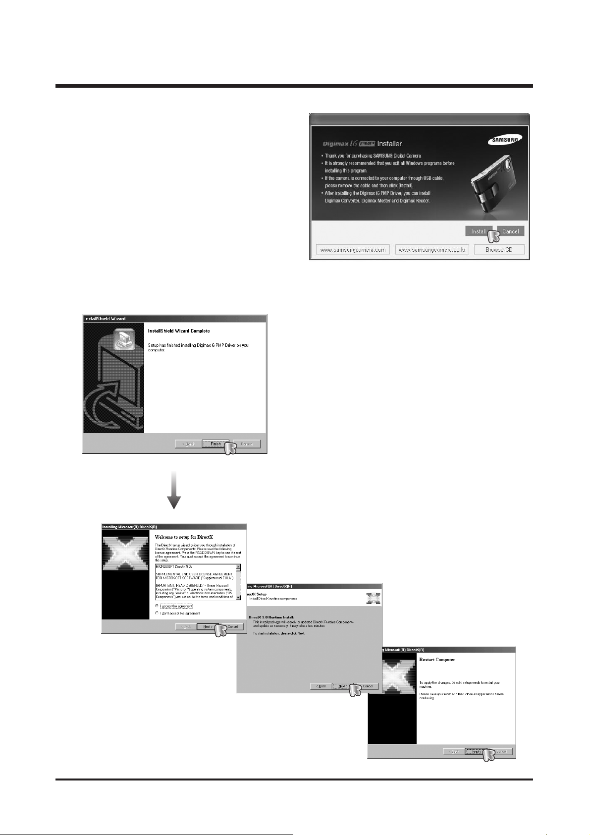
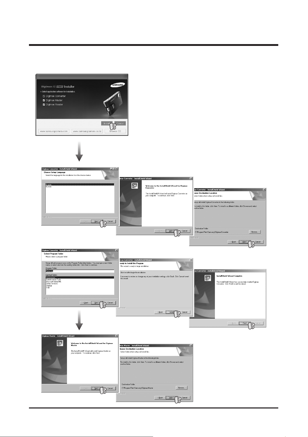
1. The auto run frame will display.
Click the [Install] menu in the Auto run frame.
2. Install the camera driver and DirectX by selecting a button shown on the monitor.
Page 14
14
Ⅱ.INSTALLATION&FAQ
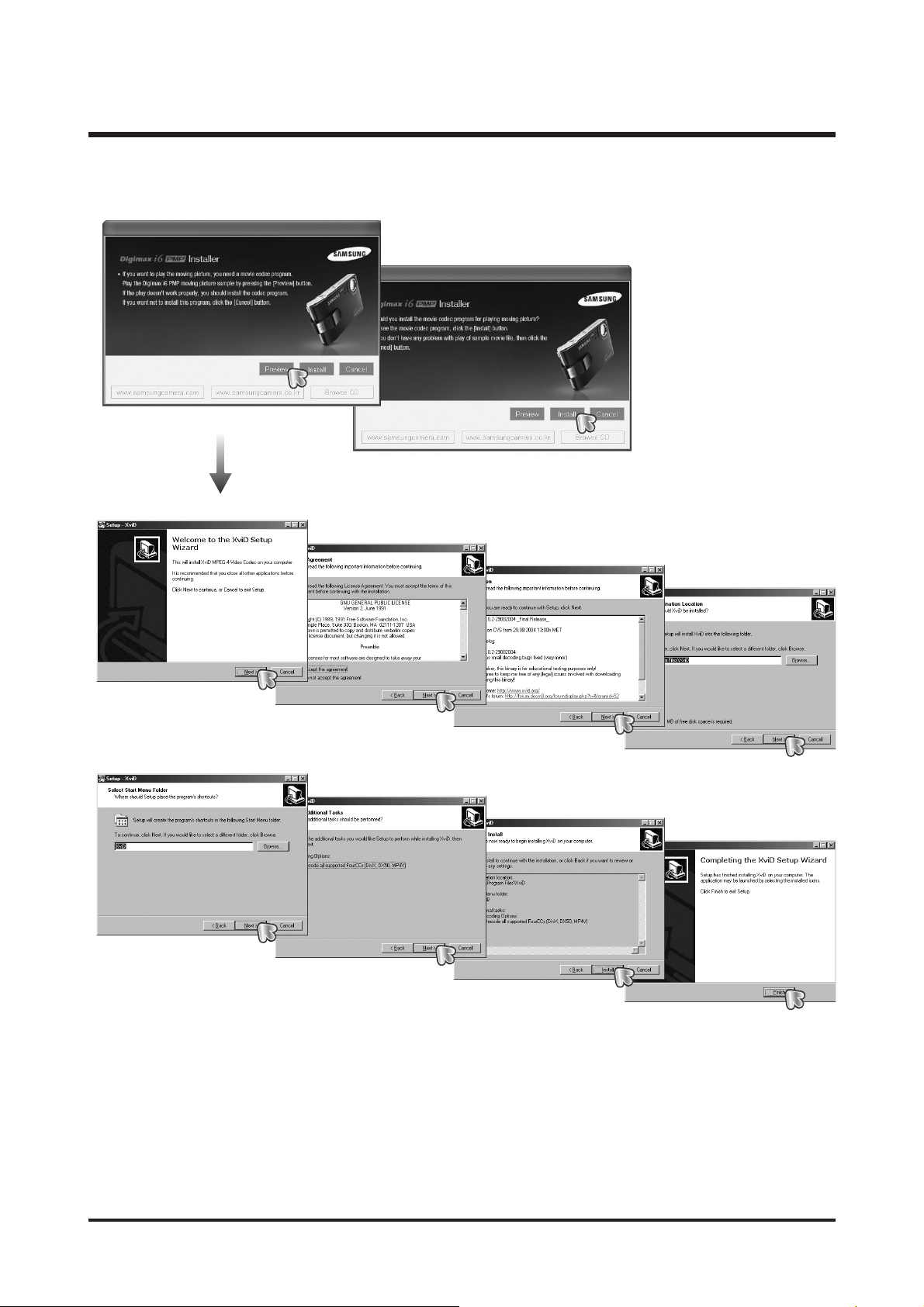
3. To play back the movie clip recorded with this camera on the computer, install the XviD codec.
※ The XviD codec is distributed according to and under the terms and conditions of the GNU General Public
License and everyone can copy, modifiy and distribute this codec freely, but WITHOUT ANY WARRANTY,
IMPLIED OR EXPRESSED, OF MERCHANTABILITY OR FITNESS FOR A PARTICULAR PURPOSE;
provided, however, that you have to follow the GNU General Public License whenever you are distributing this
codec or modification thereof.
For more information see the GNU General Publice License documents (http://www.gnu.org/copyleft/gpl.html).
Page 15
15
Ⅱ.INSTALLATION&FAQ
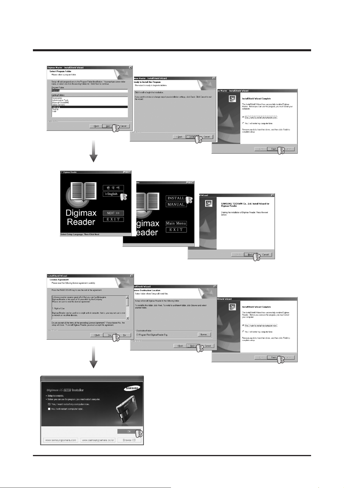
4. Install the Digimax Converter, Digimax Master and Digimax Reader in order.
Page 16
16
Ⅱ.INSTALLATION&FAQ
Page 17

17
Ⅱ.INSTALLATION&FAQ
● If you have installed the camera driver, The [Found New Hardware Wizard] may not open.
● On a Windows 98 or 98 SE system, the Found New Hardware Wizard dialog box opens and a window
asking you to select a driver file may appear. In this case, specify "USB Driver" in the CD supplied.
5. After restarting the computer, connect the PC to the
camera with the USB cable.
6. Turn the camera power on.
The [Found New Hardware Wizard] will open and the
computer will recognize the camera.
※ If your OS is Windows XP, an image viewer program will
open.
If the download window of Digmax Master opens after
starting Digimax Master, the camera driver was setup
successfully.
Page 18

18
Ⅱ.INSTALLATION&FAQ
i6 PMP SW FAQ
<< For Windows >>
* System Requirements
- Windows 98/98SE, ME, 2000, XP
(Digimax Master can be installed and run in the Windows 98FE but that is not covered by Samsung's warranty)
- Pentium Ⅱ 450MHz or higher (Pentium 700MHz recommended)
- Minimum 200MB hard disk space (1GB recommended) / Minimum 128MB RAM
- 1024X768 pixels, 16-bit colour display compatible monitor / DirectX 9.0 or later
< Using the Digimax Converter >
- Windows 98SE/2000/ME/XP (Windows 2000/XP recommended)
- Pentium Ⅲ 500MHz or higher (Pentium Ⅳrecommended)
※ For more information about the USB, DirectX, XviD, MP3, Digimax Master, Macintosh, refer to the i5
MP3 C/S Manual and "FAQ of DRM MP3 files".
Q1. What is the file name of USB Driver for Windows 98/98SE?
A1. SL2-63.inf, DSCPDR.pdr, DSCSYS.sys
Q2. When playing back an MP3 file, "TICK" sound can be heard.
A2. We should modify the camera but, follow the instruction so far.
When an MP3 that contain ID3 tag Ver 1.0 is played back, the sound can be heard.
ID3 tag is for including title, name of singer and Album title in the file. ID3 tag v2.0 is usually used but ID3 tag
v1.0 is still used. The sound can be removed by using MP3 converting program. You can find it by using
internet. After converting the file,the sound may disappear.
▶ Digimax Converter
Multimedia (Movie, Video clip, etc) files can be converted into movie clips that can be played back on this
camera. This software is only compatible with Windows.
For more information about the Digimax Converter, refer to the User manual or Help menu of this program.
Q1. What do I check before using the program?
A1. (1) DirectX 9.0C must be installed.
(2) Check the converted file can be played back on the Windows Media Player.
Files can be played back on the Windows Media Player can be converted.
If a file can't be played back, install the multi-codec.
(3) After installing the multi-codec on your computer, install the Digimax Converter.
Page 19
19
Ⅱ.INSTALLATION&FAQ
Q2. Which codec can be compatible with this camera and Digimax Converter?
A2. This camera supports "Modified XviD MPEG4 Video, MPEG Layer2 Audio" type AVI file only.
Digimax Converter embeds XviD codec. It can convert "XviD, DivX 4, 5 type movie and mp3 audio file"
- Source file format : AVI, MOV, WMV, ASF, MPG (MPEG1)
Converted files are saved as AVI file type that can be played back on the camera. If the file can't be
converted, "Can't be converted" message will display.
Q3. I only set up the Digimax Converter. If there are any files that can't be converted, how can I convert the files?
A3. Download the free multi-codec on the web and install the codec.
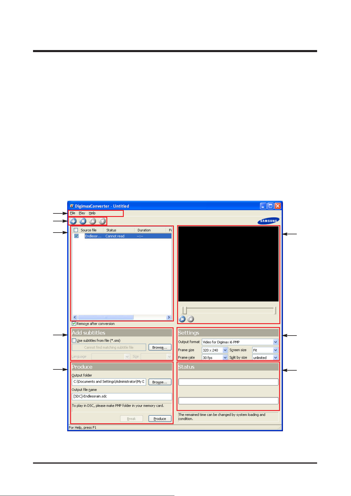
Q4. Brief instruction of Digimax Converter' GUI
①
②
③
④
⑤
⑥
⑦
⑧
Page 20

20
Ⅱ.INSTALLATION&FAQ
① Menu List
② Toolbar Icon
- Add/Remove file, Sort files on the List
③ Batch List
- The files are converted by order of the List. Only the checked files can be converted.
- You can use the Mouse as like the Windows Explorer
(Multiple selecting, Function of right button, etc.)
④ Subtitle
- Af for the script file, SMI file type can be compatible.
- To see the script automatically, the script file must be at folder where the movie is saved and must has same
file name with the movie.
- Or, select the script file (*.smi) by using the "Search" button.
- Threre are three type of font size (Standard, Large, Small)
- Regardless of the file settings, the font color (white) and font out-line (Black) are fixed.
⑤ Produce
- You can select folder where each converted files are saved and each file names on the Batch List.
- If you not select any folders and file names, the converted files are saved on a folder where the source files
are, and saved as same file name with the source file ([SDC] tag will be added in front of the file name).
⑥ Preview Window
- You cann preview the selected image on the preview window (320X240).
- With this program, you can trim the movie. Some movies may not be trimmed.
⑦ Conversion Setting
- Movie size : When a 16:9 movie that is displayed, you can adjust/trim/expand the ratio of the movie size.
File Playback Help
Add
(Adds files that you want to convert in the Batch List)
Remove (Removes the added files from the Batch List)
Open (Opens the saved Batch List file)
Properties (Informations of movie)
Exit
Save As
(Saves file as DMC file type that has converting
information)
Playback (Plays back file that was
selected on the Preview window)
Help
Samsung Camera web site
InformationStop
Pause
[Adjusting] [Trimming] [Expanding]
Page 21

21
Ⅱ.INSTALLATION&FAQ
- Dividing file size : If the movie is too big to save it in a merory card, it can be divided into any size you want to.
No Limit : It is divided into a file of movie regardless of file size.
32MB ~ 512MB : It is divided into a size you selected.
⑧ Conversion Status Bar
- Though a file can't be converted, the numbers of converted files will not change.
< INFORMATION > Converting time
(Ex1) In Good Company (≒700MB, 640X352)
(EX2) Hello Cap (≒700MB, 640X352)
<< For Macintosh >>
* System Requirements
- Power Mac G3 or later
- Mac OS 9.0~10.4
- Minimum 64MB RAM
- Minimum 110MB hard disk space
< Playing back a movie >
- Mac OS 10.1~10.4
- MPlayer, VCL Media Player
320x240 / 30fps 640x480 / 30fps
AMD 1.4GH, 256MB 1H 7'M '' 2H 26' 10''
Intel 1.4G, 256MB 1H 4' 39'' 2H 3' 3''
Intel 1G, 256MB 1H 17' 10'' 3H 5' 32''
Intel 866M, 224MB 1H 39' 25'' 4H 6' 40''
320X240/30fps 1H 19' 43'' 21' 29'' 223MB
640X480/30fps 3H 36' 02'' 50' 13'' 420MB
Intel 866MHz, 512MB
Digimax
Converter
JetAudio
480X264/Auto
fps/768Kbps,
MP3/128Kbps
2H 04' 25'' 35' 47'' 316MB
Intel 2.8GHz, 512MB
Converted
file size
Page 22
22
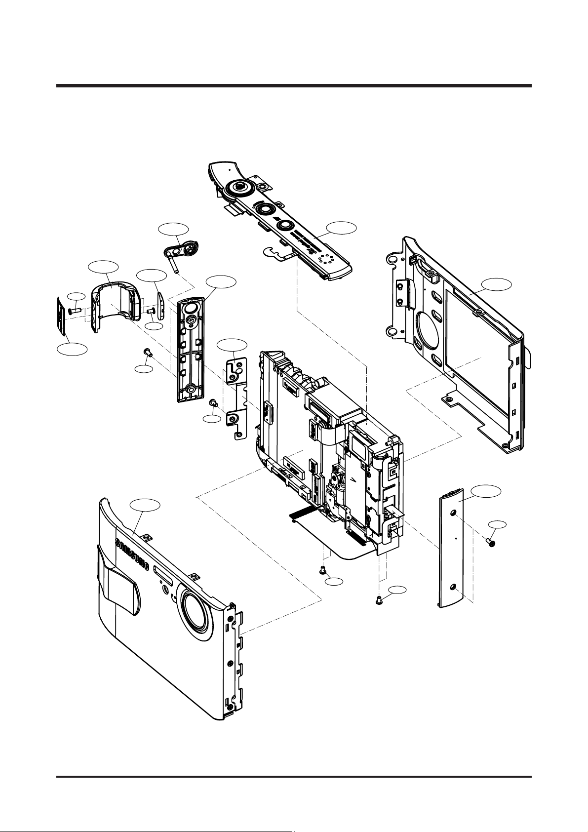
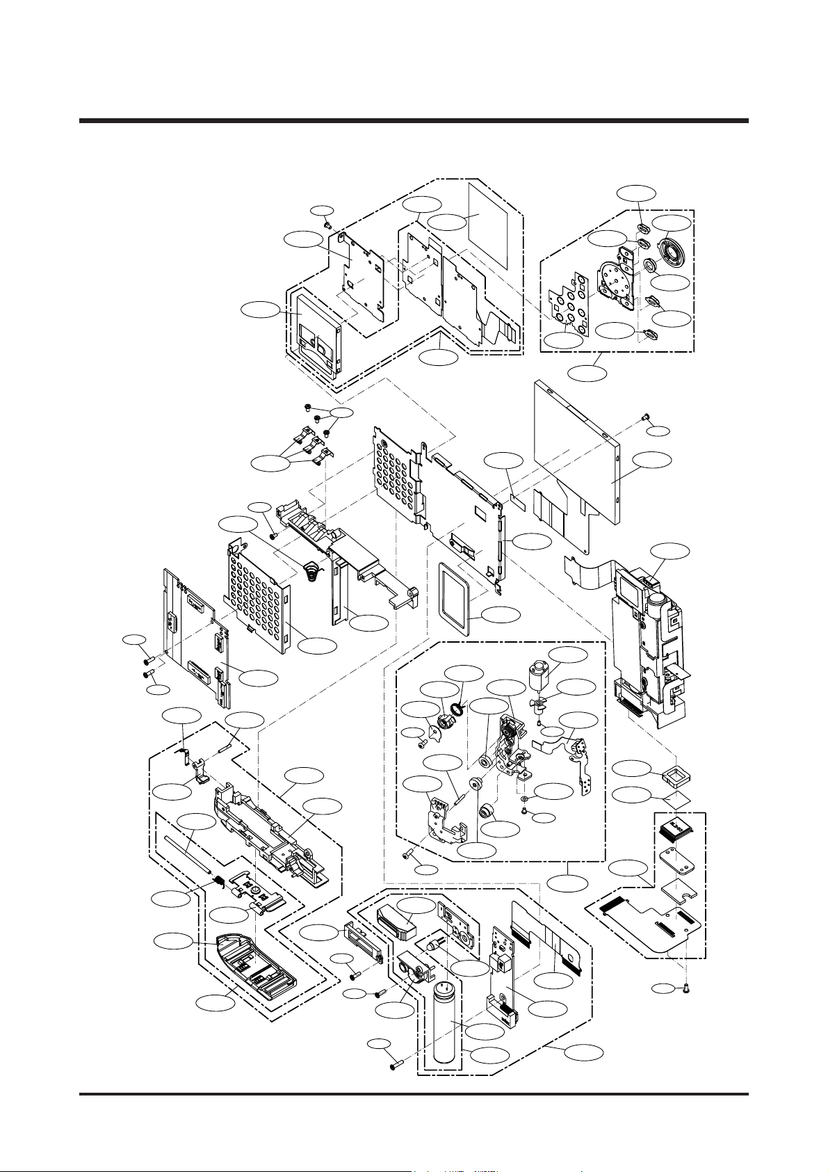
Ⅲ.EXPLODEDVIEWANDPARTLIST
1-1
1-2
1-9
1-12
1-3
1-5
1-3
1-11
1-14
1-10
1-7
1-4
1-4
1-6
1-6
1-8
1-4
1. MAIN ASSEMBLY
Page 23

23
Ⅲ.EXPLODEDVIEWANDPARTLIST
▶
PARTS LIST
1-1 Q9007257601A GRIP DECO ASSY 1 O SILVER
Q9007252201A GRIP DECO ASSY 1 O BLACK
1-2 Q7017051502B STRAP HOLDER DECO 1 O
1-3 Q7217371006A MIDDLE COVER R 1 O TITAN
Q7217371007A MIDDLE COVER R 1 O
BLACK/SILVER
1-4 Q6001018401A SCREW 5 X
1-5 Q7017051402A COVER PLATE 1 O
1-6 Q6001018301A SCREW 4 X
1-7 Q6001018501A SCREW 2 X
1-8 Q6003048601A SCREW 2 X SILVER
Q6003049201A SCREW 2 X BLACK
1-9 Q7217380001A STRAP HOLDER 1 O SILVER
Q7217371402B STRAP HOLDER 1 O BLACK
1-10 Q9007257301A FRONT COVER ASSY-DIGIMAX 1 O SILVER
Q9007251801A FRONT COVER ASSY-DIGIMAX 1 O BLACK
Q9007257201A FRONT COVER ASSY-KENOX 1 O SILVER
Q9007257001A FRONT COVER ASSY-KENOX 1 O BLACK
1-11 Q9007256901A BACK COVER ASSY 1 O SILVER
Q9007252001A BACK COVER ASSY 1 O BLACK
1-12 Q7217370905A MIDDLE COVER L 1 O SILVER
Q7217370905A MIDDLE COVER L 1 O BLACK
1-13 Q7217374002A EAR CAP 1 O
1-14 Q9007251601A MIDDLE COVER ASSY 1 O
Fig.No Parts No. Parts Name Q’ty
Supply Available Parts
Remarks
Page 24
24
Ⅲ.EXPLODEDVIEWANDPARTLIST
2-17
2-20
2-19
2-46
2-21
2-31
2-29
2-26
2-25
2-18
2-24
2-27
2-23
2-22
2-28
2-32
2-65
2-30
2-63
2-61
2-60
2-59
2-38
2-15
2-37
2-39
2-13
2-10
2-11
2-12
2-9
2-2
2-5
2-7
2-3
2-8
2-1
2-4
2-6
2-16
2-36
2-14
2-35
2-34
2-40
2-54
2-57
2-56
2-55
2-58
2-53
2-51
2-50
2-52
2-45
2-48
2-46
2-42
2-49
2-47
2-41
2-43
2-44
2-62
2-33
2-65
2-33
2-65
2-52
2-66
2-62
2-64
2-62
2. BODY ASSEMBLY
Page 25

25
Ⅲ.EXPLODEDVIEWANDPARTLIST
▶▶
PARTS LIST
2-1 Q9007251301A KEY PAD ASSY 1 O
2-2 Q7307006902A KEYPAD RUBBER 1 X
2-3 Q7217370203A FUNCTION BUTTON 1 X
2-4 Q7217369702A MODE BUTTON 1 X
2-5 Q7217370003B NAVI BUTTON 1 X
2-6 Q7217369802B EFFECT BUTTON 1 X
2-7 Q7217370103A OK BUTTON 1 X
2-8 Q7217369902A PLAY BUTTON 1 X
2-9 Q9008098401A CARD ASSY 1 O
2-10 Q3708013901A CARD SOCKET 1 O
2-11 Q7011055403A CARD PLATE 1 X
2-12 Q7409212003A CARD PCB DOME SHEET 1 X
2-13 Q9008098501A CARD F PCB SMD ASSY 1 X
2-14 Q9008098701A MAIN PCB ASSY 1 O
2-15 Q7011055106A MAIN FRAME 1 O
2-16 Q7211083404B UPPER HOLDER 1 O
2-17 Q9001103501A MOTOR ASSY 1 O
2-18 Q7017048201A ROTATOR PLATE 1 O
2-19 Q7217352606A LC GEAR BASE 1 O
2-20 Q7217352704A LC GEAR COVER 1 O
2-21 Q7212177003B ZOOM MOTOR GEAR 1 O
2-22 Q7217351203A LC GEAR_A 1 O
2-23 Q7217351301A LC GEAR_B 1 O
2-24 Q7217351401A LC IDLE GEAR 1 O
2-25 Q7217351508A LC ROTATOR GEAR 1 O
2-26 Q6107063603A ROTATOR SPRING 1 O
2-27 Q7411118701A LC GEAR SHAFT 1 O
2-28 Q7411118803A LC MOTOR GEAR PIN 1 O
2-29 Q9001104101A LC MOTOR PCB ASSY 1 O
2-30 Q6001010601A SCREW 1 X
2-31 Q6031006601A MOTOR WASHER 1 X
2-32 Q6001017601A SCREW 1 X
2-33 Q0961900101A SCREW 7 X
Fig.No Parts No. Parts Name Q’ty
Supply Available Parts
Remarks
Page 26

26
Ⅲ.EXPLODEDVIEWANDPARTLIST
▶▶
PARTS LIST
2-34 Q7011055504A BATTERY CONTACT 3 O
2-35 Q6107064001A BATTERY SPRING 1 O
2-36 Q7011055004A TOP COVER 1 O
2-37 Q7409210702B BARREL BASE SPONGE-S 1 O
2-38 Q0704012401A LCD 1 O
2-39 Q7409219402A LCD TAPE 1 X
2-40 Q9007257401A BOTTOM ASSY 1 O SILVER
Q9007251401A BOTTOM ASSY 1 O BLACK
2-41 Q7211083305B BOTTOM HOLDER 1 O
2-42 Q7211083202C BATTERY LOCK 1 O
2-43 Q7011055303A LOCK PLATE SPRING 1 O
2-44 Q7411122701A LOCK HINGE 1 O
2-45 Q9007251501A BATTERY COVER ASSY 1 O SILVER
Q9007258101A BATTERY COVER ASSY 1 O BLACK
2-46 Q7211084001A BATTERY COVER 1 O SILVER
Q7211082705B BATTERY COVER 1 O BLACK
2-47 Q7411122801A BATTERY HINGE 1 O
2-48 Q7011055205A BATTERY PLATE 1 O
2-49 Q6107066902A HINGE SPRING 1 O
2-50 Q7211083103A STROBO COVER 1 O
2-51 Q5900009301A FLASH MODULE 1 X
2-52 Q7211083005A AF LED HOLDER 1 X
2-53 Q0408001201A AF LED 1 O
2-54 Q9004086501A SUB PCB ASSY 1 O
2-55 Q9004086601A STROBO PCB ASSY 1 O
2-56 Q9008098201A STROBO ASSY 1 O
2-57 Q4101035701A SUB FPCB 1 O
2-58 Q2401009001A MAIN CAPACITOR 1 O
2-59 Q9002138201A BARREL ASSY 1 O
2-60 Q7309046101A OLPF CUSHION 1 O
2-61 Q2904003001A IR CUT FILTER 1 O
2-62 Q0961900301A SCREW 4 X
2-63 Q9008098601A CCD F PCB SMD ASSY 1 O
Fig.No Parts No. Parts Name Q’ty
Supply Available Parts
Remarks
Page 27

27
Ⅲ.EXPLODEDVIEWANDPARTLIST
▶▶
PARTS LIST
2-64 Q6001018601A SCREW 1 X
2-65 Q6003018501A MACHINE SCREW 3 X
2-66 Q6001017701A SCREW 1 X
Fig.No Parts No. Parts Name Q’ty
Supply Available Parts
Remarks
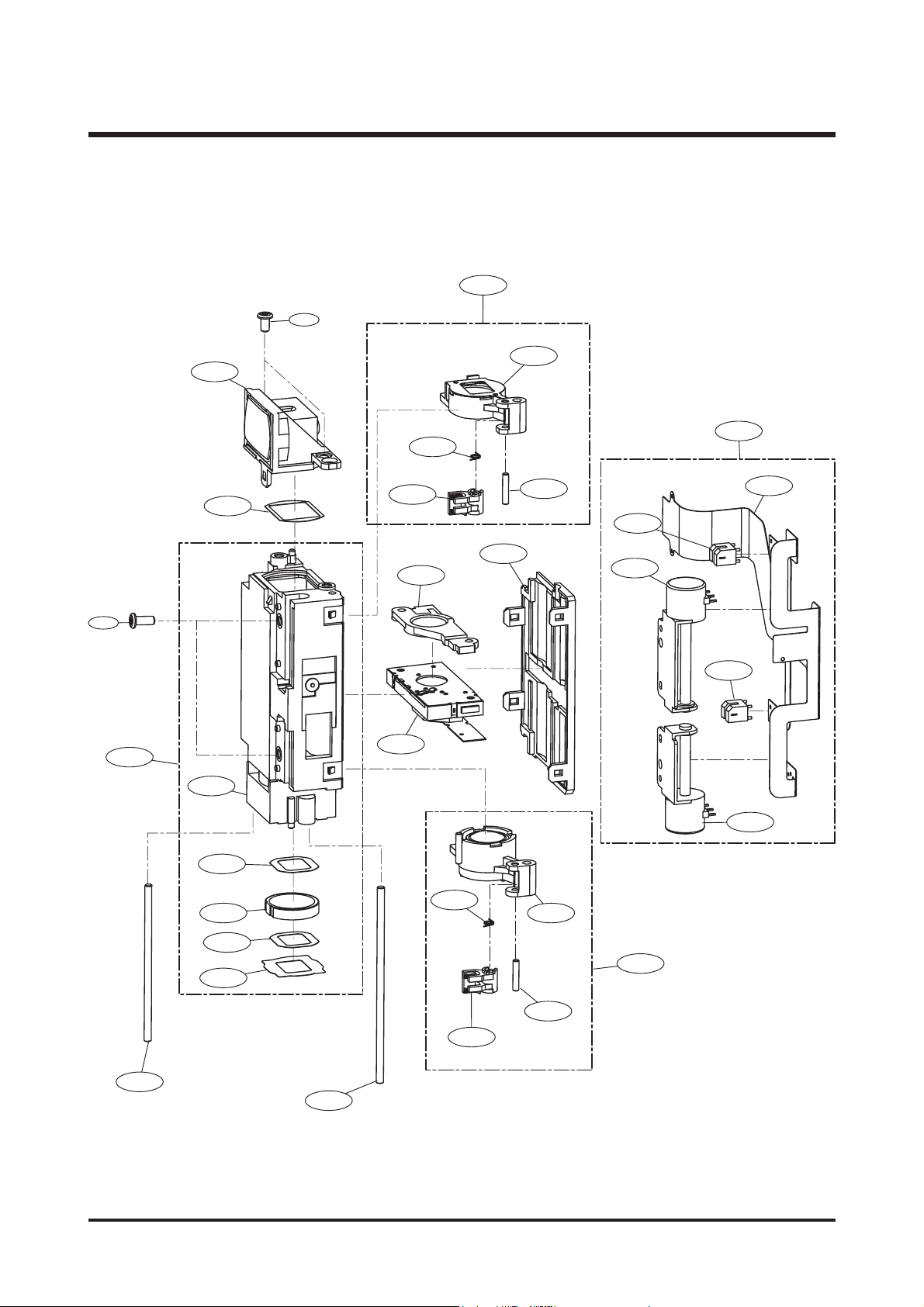
Page 28
28
Ⅲ.EXPLODEDVIEWANDPARTLIST
3. BARREL ASSEMBLY
3-28
3-27
3-10
3-11
3-19
3-13
3-20
3-26
3-12
3-14
3-21
3-25
3-8
24
3-
3-22
3-21
3-7
3-1
3-2
3-23
3-3
3-13
3-4
3-16
3-9
3-5
3-15
3-6
3-14
3-17
3-18
Page 29

29
Ⅲ.EXPLODEDVIEWANDPARTLIST
▶▶
PARTS LIST
3-1 Q9002138001A 5TH BARREL ASSY 1 O
3-2 Q7212185008A LENS BASE 1 X
3-3 Q7012083402A G11 MASK_A 1 X
3-4 Q6713005001A G11 LENS 1 X
3-5 Q7012082501A G11 MASK 1 X
3-6 Q7409179001A REAR SHEET 1 X
3-7 Q9005017801A SHUTTER ASSY 1 O
3-8 Q9002135301A 3RD LENS BARREL ASSY 1 O
3-9 Q7411115602A GUIDE BAR_B 1 O
3-10 Q9002137801A 2ND CLIP ASSY 1 O
3-11 Q9002135201A 2ND MOVE BARREL ASSY 1 X
3-12 Q7212185604A 2ND CLIP 1 X
3-13 Q6107060603A CLIP SPRING 1 X
3-14 Q7411115701A CLIP GUIDE BAR 1 X
3-15 Q9002137901A 4TH CLIP ASSY 1 O
3-16 Q9002135401A 4TH MOVE BARREL ASSY 1 X
3-17 Q7212185704A 4TH CLIP 1 X
3-18 Q7411115502A GUIDE BAR_A 1 O
3-19 Q9002138101A MAIN FPCB ASSY 1 O
3-20 Q4101030402A MAIN FPCB 1 X
3-21 Q0608001001A PHOTO INTERRUPTER 2 O
3-22 Q3107002201A 2nd MOTOR 1 O
3-23 Q3107002301A 4th MOTOR 1 O
3-24 Q6003000201A SCREW B 2 X
3-25 Q7212185502A BARREL COVER 1 O
3-26 Q7012082701A G3 MASK 1 X
3-27 Q9002135101A 1ST LENS BARREL ASSY 1 O
3-28 Q0961900101A SCREW 2 X
Fig.No Parts No. Parts Name Q’ty
Supply Available Parts
Remarks
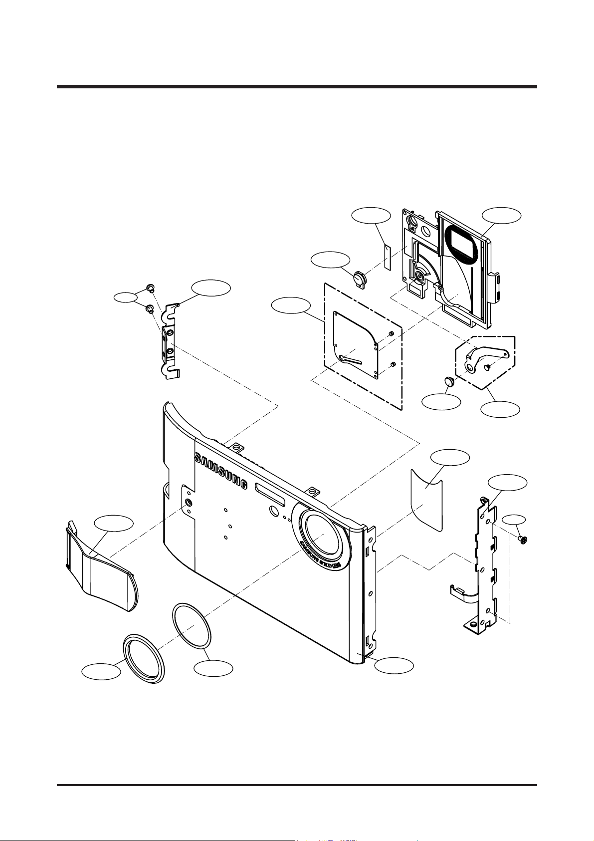
Page 30
30
Ⅲ.EXPLODEDVIEWANDPARTLIST
4-4
4-7
4-16
4-14
4-154-12
4-11
4-13
4-9
4-1
4-3
4-2
4-5
4-10
4-6
4. FRONT COVER ASSEMBLY
Page 31

31
Ⅲ.EXPLODEDVIEWANDPARTLIST
▶▶
PARTS LIST
4-1 Q7117015301A DIGIMAX FRONT COVER 1 X SILVER
Q7117013603A DIGIMAX FRONT COVER 1 X BLACK
Q7117015501A KENOX FRONT COVER 1 X SILVER
Q7117015101A KENOX FRONT COVER 1 X BLACK
4-2 Q7004000702A LENS DECO 1 O
4-3 Q7409212101B LENS DECO TAPE 1 X
4-4 Q7409218002B LC SHEET 1 X
4-5 Q7217379901A FRONT DECO 1 O SILVER
Q7217371104A FRONT DECO 1 O BLACK
4-6 Q0961900101A SCREW 1 X
4-7 Q7017051203A FRONT PLATE R 1 X
4-8 Q6001018301A SCREW 2 X
4-9 Q7017051103A FRONT PLATE L 1 X
4-10 Q6001018301A SCREW 2 X
4-11 Q7211082901A AF LED WINDOW 1 X
4-12 Q7409218101A LC TAPE 1 X
4-13 Q9007251901A LENS COVER ASSY 1 X
4-14 Q7411118902A LC LEVER SHAFT 1 X
4-15 Q7217371502A LENS COVER BASE 1 X
4-16 Q9007252901A LEVER ASSY 1 X
Fig.No Parts No. Parts Name Q’ty
Supply Available Parts
Remarks
Page 32

32
Ⅲ.EXPLODEDVIEWANDPARTLIST
5-12
5-15
5-11
5-14
5-2
5-5
5-10
5-13
5-9
5-1
5-4
5-3
5-6
5-8
5-7
5. MIDDLE COVER ASSEMBLY
Page 33

33
Ⅲ.EXPLODEDVIEWANDPARTLIST
▶▶
PARTS LIST
5-1 Q7217370806A MIDDLE COVER 1 O
5-2 Q7217370302B POWER BUTTON 1 O
5-3 Q7217369602B RELEASE BUTTON 1 O
5-4 Q6107067101A RELEASE SPRING 1 O
5-5 Q7217370702A ZOOM BUTTON 1 O
5-6 Q7411123101A ZOOM BUTTON HINGE 1 O
5-7 Q0961900101A SCREW 3 X
5-8 Q9007251701A TOP KEY ASSY 1 O
5-9 Q7017051003A TOP KEY PLATE 1 X
5-10 Q3003000401A MIC 1 O
5-11 Q3722003801A EARPHONE JACK 1 O
5-12 Q3001000601A SPEAKER 1 O
5-13 Q7409211801A POWER METAL DOME SHEET 1 X
5-14 Q7409211901A ZOOM METAL DOME SHEET 1 X
5-15 Q9008098901A TOP F PCB SMD ASSY 1 X
Fig.No Parts No. Parts Name Q’ty
Supply Available Parts
Remarks
Page 34

34
Ⅲ.EXPLODEDVIEWANDPARTLIST
6-3
6-5
6-2
6-1
6-4
6-7
6-6
6. BACK COVER ASSEMBLY
Page 35

35
Ⅲ.EXPLODEDVIEWANDPARTLIST
▶▶
PARTS LIST
6-1 Q7117015201A BACK COVER 1 X SILVER
Q7117013702A BACK COVER 1 X BLACK
6-2 Q7217381901A ZOOM BUTTON DECO 1 X SILVER
Q7217371203B ZOOM BUTTON DECO 1 X BLACK
6-3 Q7217369401A FUNCTION LAMP WINDOW 1 X
6-4 Q7409211002A TFT LCD WINDOW 1 X
6-5 Q7017051302A BACK PLATE 1 X
6-6 Q6001018301A SCREW 1 X
6-7 Q7409210902A LCD SPONGE 1 X
Fig.No Parts No. Parts Name Q’ty
Supply Available Parts
Remarks
Page 36

36
Ⅲ.EXPLODEDVIEWANDPARTLIST
7. CRADLE ASSEMBLY
7-3
7-1
7-8
7-4
7-9
7-7
7-2
7-5
7-5
7-5
7-5
7-6
Page 37

37
Ⅲ.EXPLODEDVIEWANDPARTLIST
▶▶
PARTS LIST
7-1 Q7204027901A TOP CASE 1 X
7-2 Q7204028001A BOTTOM CASE 1 X
7-3 Q7204028101A GUIDE 1 X
7-4 Q7209004701A IO HOLDER 1 X
7-5 Q7308016101A BUMPON 4 X
7-6 Q6002030201A SCREW 5 O
7-7 Q9008100601A PCB MAIN 1 O
7-8 Q9008100701A PCB SUB 1 O
7-9 Q9008100801A CABLE ASS'Y 1 O
Fig.No Parts No. Parts Name Q’ty
Supply Available Parts
Remarks
Page 38

38
Ⅲ.EXPLODEDVIEWANDPARTLIST
8. PACKING ITEM
8-7 8-17 8-238-18 8-15
8-20 8-21 8-19
8-22
8-16
8-24
8-25
8-1
8-9
8-8
8-14
8-26
8-12
8-6
8-5
8-3
8-4
8-13
8-2
8-11
8-10
8-27
Page 39

39
Ⅲ.EXPLODEDVIEWANDPARTLIST
▶
PARTS LIST
8-1 QP960210101A PE BAG (FOR CAMERA) 1
8-2 Q6909018201A PE BAG (FOR ACCESSORY) 1
8-3 Q6901232001A CABLE_INNER PAD_i6_KOR/EXP 1
8-4 Q6901232101A BODY_INNER PAD_i6 1
8-5 Q6901233101A Normal_inner pad_i6 1
8-6 Q6901233201A Normal_inner cover_i6 1
8-7 Q7409218801A STRAP_Digimax i6_KOR/EXP_Silver 1 SILVER
Q7409222501A STRAP_Digimax i6_KOR/EXP_Black 1 BLACK
8-8 Q4609013101A
Driver+Digimax Master+Digimax Reader+Digimax Converter
1
8-9 Q6909016902A AIR BAG_Digimax i5_EXP(FOR BODY) 1
8-10 Q6904028501A POUCH_Digimax i6_KOR/EXP_Silver 1 SILVER
Q6904029001A POUCH_Digimax i6_KOR/EXP_Black 1 BLACK
8-11 Q6806309901A Q/GUIDE_Digimax i6_ENG 1
Q6806309801A Q/GUIDE_KENOX i6_KOR 1
Q6806310001A Q/GUIDE_Digimax i6_GER 1
Q6806310101A Q/GUIDE_Digimax i6_FRA 1
Q6806310201A Q/GUIDE_Digimax i6_SPA 1
Q6806310301A Q/GUIDE_Digimax i6_ITA 1
Q6806310401A Q/GUIDE_Digimax i6_CHI(T) 1
Q6806310501A Q/GUIDE_Digimax i6_DUT 1
Q6806310601A Q/GUIDE_Digimax i6_POR 1
Q6806310701A Q/GUIDE_Digimax i6_SWE 1
Q6806310801A Q/GUIDE_Digimax i6_DEN 1
Q6806310901A Q/GUIDE_Digimax i6_FIN 1
Q6806311001A Q/GUIDE_Digimax i6_RUS 1
Q6806311101A Q/GUIDE_Digimax i6_CHI(S) 1
Q6806311201A Q/GUIDE_Digimax i6_TK 1
Q6806311301A Q/GUIDE_Digimax i6_IND 1
Q6806311401A Q/GUIDE_Digimax i6_ARA 1
8-12 Q6806311601A U/MANUAL_Digimax i6_ENG 1
Q6806311501A U/MANUAL_KENOX i6_KOR 1
Q6806311701A U/MANUAL_Digimax i6_GER 1
Q6806311801A U/MANUAL_Digimax i6_FRA 1
Q6806311901A U/MANUAL_Digimax i6_SPA 1
Q6806312001A U/MANUAL_Digimax i6_ITA 1
Q6806312101A U/MANUAL_Digimax i6_CHI(T) 1
Fig.No Parts No. Parts Name Q’ty Remarks
Page 40

40
Ⅲ.EXPLODEDVIEWANDPARTLIST
▶
PARTS LIST
Q6806312201A U/MANUAL_Digimax i6_DUT 1
Q6806312301A U/MANUAL_Digimax i6_POR 1
Q6806312401A U/MANUAL_Digimax i6_SWE 1
Q6806312501A U/MANUAL_Digimax i6_DEN 1
Q6806312601A U/MANUAL_Digimax i6_FIN 1
Q6806312701A U/MANUAL_Digimax i6_RUS 1
Q6806312801A U/MANUAL_Digimax i6_CHI(S) 1
Q6806312901A U/MANUAL_Digimax i6_TK 1
Q6806313001A U/MANUAL_Digimax i6_IND 1
Q6806313101A U/MANUAL_Digimax i6_ARA 1
8-13 Q6807003003U WARRANTY CARD_EXP 1
QP955150101F WARRANTY CARD_KOREA 1
Q6807012301A WARRANTY CARD_2 YEARS 1
Q6807010903C WARRANTY CARD_RUS(3 YEARS) 1
Q6807011301B WARRANTY CARD_TSOE(CHINA) 1
Q6807009502E CARD_PRODUCT(Mexico) 1
Q6807012101A WARRANTY CARD_IRAN 1
Q6804012401A WARRANTY CARD_TURKEY 1
8-14 Q6901226101A G/T BOX_Digimax i6_EXP/AUS_SILVER 1
Q6901226301A G/T BOX_Digimax i6_EXP/AUS_CRADLE_SILVER 1
Q6901233001A G/T BOX_Digimax i6_CHI(S)_CHARGE 1
Q6901225901A G/T BOX_KENOX i6_KOR_Silver 1
8-15 Q4302001101A LITHIUM-ION_SLB-0837 1
8-16 Q4401001701A CRADLE_SCC_S6 1
8-17 Q4401001101A AC_ADAPTOR_4.2V (SAC-42)_EXP 1
Q4401001001A AC_ADAPTOR_4.2V (SAC-42)_KOR 1
Q4401001201A AC_ADAPTOR_4.2V (SAC-42)_USA 1
Q4401001301A AC_ADAPTOR_4.2V (SAC-42)_UK 1
Q4401001401A AC_ADAPTOR_4.2V (SAC-42)_AUS 1
Q4401001501A AC_ADAPTOR_4.2V (SAC-42)_TSOE 1
8-18 Q9010054701A TRIPOD HOLE CONNECTOR-Silver 1 SILVER
Q9010054101A TRIPOD HOLE CONNECTOR-black 1 BLACK
8-19 Q3009000501A Earphone Digimax i6 (EP-360)_White 1 SILVER
Q3009000601A Earphone Digimax i6 (EP-360)_Black 1 BLACK
8-20 Q3802004701A 24PIN USB Cable_Digimax i6 1
8-21 Q3802004801A 24PIN AV CABLE_Digimax i6 1
Fig.No Parts No. Parts Name Q’ty Remarks
Page 41

41
Ⅲ.EXPLODEDVIEWANDPARTLIST
▶
PARTS LIST
8-22 Q4309002001A CHARGER_SBC-L5 1
8-23 Q1107002801A Multi Media Card (64MB) Samsung 1
Q1107002901A Multi Media Card (128MB) Samsung 1
Q1107003001A Multi Media Card (256MB) Samsung 1
Q1107003101A Multi Media Card (512MB) Samsung 1
Q1107003201A Multi Media Card (1GB) Samsung 1
8-24 Q7409219101A HOLOGRAM STICKER_Digimax i6 1
8-25 Q7409219001A FCC LABEL_DIGIMAX I6(MAIN IN KOREA) 1
Q7409218901A MIC LABEL_KENOX #11 (MADE IN KOREA) 1
8-26 Q6804096001A COLOR STICKER_Digimax S500_BLACK 1 BLACK
8-27 Q6804097901A BAR_STICKER_Digimax i6_EXP/AUS_BLACK 1 BLACK
Q6804098101A
BAR_STICKER_Digimax i6_EXP/AUS_CRADLE_SILVER
1 SILVER
Q6804102001A BAR_STICKER_KENOX #11_Black 1 BLACK
Fig.No Parts No. Parts Name Q’ty Remarks
Page 42

42
Ⅳ.ADJUSTMENT
1. Digital camera service
To take a digital camera service (Repair, Tuning and Checking), the following equipments have to be arranged.
The sequences for the camera service are as shown.
1. Receiving the camera
When receiving a camera, check whether the accessories are
included or not and ask the customer exact problems.
2. Checking the camera
Checking the camera with priority given to the exact problems
to find overall malfunctions.
3. Repairing the camera
Repair the camera malfunctions found at the step 2.
4. Inspection
After repairing the camera, inspect all of the camera functions.
※ The illustrations may be different from the real display in accordance with the camera model.
1. Checking the camera and Inspection
2. Repairing the camera 3. Tuning
Receiving the camera
Checking the camera
Repairing the camera
Tuning
Inspection
Finish
Page 43

43
Ⅳ.ADJUSTMENT
1) Equipments for checking and inspection
To check and inspect the camera malfunction, the following equipments have to be arranged.
①
②
③
⑤→
⑥
⑦
⑧
⑪
⑨→
←⑩
④
↓
No. Device Description
1 PC for inspection - Installing a digital camera driver or Checking the removable device
- Checking the file transference(upload and download)
- Playing back the still image or movie clip
2 HARD RACK, For the compatibility test.
by Operating System by the O/S(WIN 98SE, ME, 2000, XP)
3
Driver CD, by camera models
S/W CDs for installing a camera driver
4 USB HUB For using all kinds of USB cable at a time
5
USB cable, by camera models
For checking file transference(upload and download) by camera models
6 Chart for checking colors For checking color and image resolution before or after camera repair
7 TV MONITOR For checking video output and whether NTSC/PAL can be selected
8 Memory card by types checking card recognition by brands and sizes
9 A/V CABLE For checking whether the image can be displayed on a external monitor
10 POWER SUPPLY For checking camera power by camera models
11
Power cable by camera models
Page 44

44
Ⅳ.ADJUSTMENT
2) Equipments for camera repair
To repair the camera, the following equipments have to be arranged.
①
②
③
⑤
⑥
⑨
④
No. Device Description
1A set of tools Pincette/ Screwdriver/ Discharger etc.
2 Cleaning paper For cleaning camera lens and camera parts
3 Detergent container For containing detergent
4 Parts case For keeping various camera parts and disassembled camera parts
5 Anti-electricity mat For repairing table made from anti-electricity material
6 Soldering sponge For removing solder
7 Air pump For removing various kinds of dust
8 LIGHT BOX Color temperature 5100
9 POWER SUPPLY 7.5V 2.0A
10 Soldering iron Soldering iron that can select temperature
11 Tester Portable tester that can test AC/DC, Ω,♪ect.
12 BATTERY & AC ADAPTOR & Rechargeable battery by camera models
AC ADAPTOR - SBP3603/ SBP3605/ SBP3606
- SLB 1437
- SBP 1103
⑩→
⑧
⑪→
⑫
⑬
⑦
Page 45

45
Ⅳ.ADJUSTMENT
3) Equipments for camera tuning
To tune the camera, the following equipments have to be arranged.
①
②
③
⑤
⑥
No. Device Description
1 AE TESTER For tuning AE and STROBE
2AWB LIGHT For checking and tuning AWB
SOURCE BOX
3 COLOR chart For checking AWB and color of images
4 AF chart For tuning AF
5 Chart for checking resolution For checking image resolution
6 TRIPOD
④
Page 46

46
Ⅳ.ADJUSTMENT
4) Check list for Digital camera repair
To check the digital camera functions before/after repairing, refer to the check list.
1- Check the scratch, stain, misprint.
- Check whether the screws are turned firmly.
- Check the corrosion of terminal, bad exterior.
- Do chemical and glue test to the printing/ painting parts.
2 Insert the adapter. - Check the connecting and contact condition.
3- Insert the batteries with the correct polarity and check the contact
condition.
-
Check whether the cover is opened easily after closing.
4- The card can be inserted or removed easily and cover is closed
firmly.
-
Do inserting and removing card(SD/MMC) test two times.
→ The card must be inserted firmly and has not to spring out.
- Insert the card/batteries and give a little impact on the camera.
The camera must recognize the card and “CARD LOCKED”
message has not to be displayed.
5- When the cable is inserted, check whether the
images play back on the external monitor.
6- Check whether the green LED is blinking, SAMSUNG LOGO is on
and the start-up sound sounds.
- Check the “L” and “FINE” icon on the LCD monitor.
- Check whether the AE function is correct at the low light and high
light condition.
- Check whether the “beep” sounds on the recording and movie clip
mode.
→ The “beep”can be sounded in the microphone part.
Check that in a quiet room.
7- Press the zoom W/T button with the viewfinder.
→ Check dust and percentage of the frame seen, zoom rate.
- Press the zoom W/T button with the TFT-LCD monitor.
→
Check the zoom rate and whether the zoom bar moves smoothly.
8- Check whether the Macro icon(Flower) is displayed on the LCD
monitor.
- Check the AF in the Macro focus with the TFT-LCD monitor.
9- Check whether the subject captured from 2M has over or under
exposure and the fucus is clear.
Check the exterior of a camera.
Check the battery cover.
Check the card condition after
inserting the card.
Insert the Video cable.
Turn on the camera.
Press the zoom W/T button.
Macro focus.
Normal focus.
No. Checking item Check point
Page 47

47
Ⅳ.ADJUSTMENT
10 - Check whether the icon and counter are displayed on the LCD
monitor.
11 - Check whether the recording time is displayed and there are a
noise, dim frame and discontinuous frame in the movie clip.
12 - Check whether the zoom rate is changed and there are unclear part,
noise and dim part in the image.
- The distance from the subject is 2M and have to use the FILL IN
flash.
13 - Check whether the PLAY mode can be selected without any
problem and there are any noise, frame shaking and discoutinuous
frame.
- Check the voice recorded in the still image and the movie clip.
- Check whether the still image can be enlarged correctly with the 5
function button.
14 - Select 2 sec. of slide show interval time and check whether there are
any noise, image shaking and discontinuous frame.
15 - Check whether the mode dial is rotated with the equal force.
- Check whether each camera mode can be recognized correctly.
16 - Check whether there are unclear part, dim part, noticeable flare,
noise, ghost image and smear.
17 - Check whether all images are deleted.
18 - Check whether the “NO IMAGE” message is displayed on the
LCD monitor.
- Check whether the LARGE, FINE icon and 0018 number are
displayed.
- Check whether the camera power is turned off without any problem.
MANUAL focus.
Take a movie clip with TELE zoom
during 10 seconds.
Take a chart with TELE zoom in a
low light condition.
Play back a image with the TFT
LCD monitor.
Start the slide show
in the PLAY mode.
Try to rotate the mode dial.
Download a image from a PC with
USB cable and check the image
quality in a external monitor.
Format the card in the PLAY mode.
(Delete all images in the PLAY mode)
Check whether there is no image and
reset the camera. Remove the card
and turn off the camera.
No. Checking item Check point
Page 48

48
Ⅳ.ADJUSTMENT
2. Tuning item by changed parts
AAfter changing the electronic parts of Digimax i6 PMP, the parts have to be tuned in accordance with the tuned
items. The items listed on the table are have to be tuned after changing.
1) Equipments for tuning
▶ Equipments
- AE TESTER : AE TESTER can test upto LV 16.7
- POWER SUPPLY : 7V/2A
▶ Chart
- Focus chart
- Gray chart
2) Checking the camera
1. Remove all kinds of card. 2. Use the AC adapter or fully charged battery.
MAIN STROBO BARREL CCD
CODE PCB ASS’Y
FIRMWARE UPGRADE ●●
CCD DEFECT CELL ●●●
LENS SHADING ●●
FOCUS ADJ. ●●●
SHUTTER CLOSE TIME ADJ. ●●●
FLASH ADJ. ●●
BATTERY LEVEL ●
OB SETTING ●●●
BURNING TEST ●●● ●
EEPROM READ
EEPROM WRITE ●●●
Page 49

49
Ⅳ.ADJUSTMENT
5. After pressing the buttons like above, the firmware version will be displayed on the LCD.
4. Press the buttons as following order.
(Left 1 time → Right 1 time → Down 1 time → +/- 1 time)
3. Turn on the camera and select the Voice recording mode
(Press the Up button twice).
①①
②②
③③
④④
Page 50

50
Ⅳ.ADJUSTMENT
3. After pressing button like above, the sign “FIRMWARE UPGRADE... DO NOT TURN POWER OFF!!!” will be
shown for a second and then, LCD will be turned off automatically and LED will be blanking while updating
firmware.
3) Upgrading the firmware
1. Insert the SD card which has the firmware file and turn on the camera to enter the VOICE RECORDING mode.
※ When you update the firmware, all data in Flash memory will be reset.
Please backup the data if the customer want. File name should be “sl2.elf” and the power source
should be AC adaptor or fully charged battery.
2. Press the buttons as following order.
(Left 1 time → Right 1 time → Down 1 time → +/- 1 time)
4. After the firmware upgraded, camera will be turns
off automatically.
5. Turn on the camea and reset it in SET UP menu.
①①
②②
③③
④④
Page 51

51
Ⅳ.ADJUSTMENT
3. Adjustment
To tune all items, all kinds of code by items have to be inserted in program file and saved it to the SD card as TXT
file type. The codes are listed below.
< Description of TXT file >
<1>18;OB
<2>65535;
<3>18,1,0;Third option (process1, skip0)
<4>1;
<5>0;
<6>0,0,0,17;
<7>0,0,0,49,65535,0;
<8>23;
<9>23,2;
<10>0,1;Lens Shading,First option (process1, skip0)
<11>1;
<12>0,0,0;
<13>65535;
<14>0;
<15>0,1;ccd defect, First option (process1, skip0)
<16>1;
<17>1,3200,0,6;
<18>15000,0;
<19>65535;
<20>0;
<21>0,1;battery, First option (process1, skip0)
<22>1;
<23>130,150,127,143,136,129,125;
<24>;
<25>65535;
<26>0;
<27>0,1;shutter, First option (process1, skip0)
<28>1;
<29>1, 250, 500, 200, 100, 10;
<30>65535;
<31>0;
<32>0,1;flash,First option (process1, skip0)
<33>0;
<34>400,750,1500,90,510,550,1700,1600,3700,320,440,310,430,1,0,0;
<35>65535;
<36>0;
<37>0,1;punt,First option (process1, skip0)
<38>1;
<39>1,0,1,2,3,4,5,6,7;
<40>2,80,44,142,88,204,156,264,220,326,282,394,346,470,430,554;(50cm)
<41>42,60,50,66,52,72,58,76,60,82,58,86,62,96;
<42>65535;
<43>0;
<44>0,1;burning_current,First option (process1, skip0)
<45>1;
<46>1,4,85,87,86,12;
<47>65535;
<48>0;
If the program is saved as shown above, the file name has to be saved as SL2ADJ.TXT.
※ The SD CARD for adjusting should be formatted by computer.
※ After inserting each code, [;] mark has to be inserted.
Page 52

52
Ⅳ.ADJUSTMENT
(1) Adjustment by changed part
1) OB SETTING
After changing the MAIN PCB BLACK, tune the Black color.
< Codes of program >
< How to adjust >
a. Insert the modified codes (Type "1" on the third code of <3> and type "0" on the rest codes) and save the
program in the SD card.
b. Insert the SD card to the camera and turn on the camera.
c. The adjustment will be done automatically and <SKIP> will be displayed for other adjustment.
d. Turn off the camera.
<1>18;OB
<2>65535;
<3>18,1,1;Third option (process1, skip0)
<4>1;
<5>0;
<6>0,0,0,17;
<7>0,0,0,49,65535,0;
<8>23;
<9>23,2;
<10>0,1;Lens Shading,1번째 option (process1, skip0)
If you type the commend as "0", the OB SETTING will
be skipped. If you type the commend as "1", the OB
adjustment will be execute. Type "1" to do the OB adjustment.
If you type the first commend as "0", the
ADJUSTMENT will be skipped. If you type "1", the
adjustment will be execute.
Pr:2176 Pg:2176 Pb:2176
Cr: 1984 Cg: 1984
Cb:1984
OB OK
<SKIP Process>
< Figure 1-2>
< Figure 1-1 >
Page 53

53
Ⅳ.ADJUSTMENT
2) LENS SHADING
This will adjust the brightness gaps between center of the lens and around the lens.
< Codes of program >
< How to adjust the item >
a. Prepare a AE TESTER that can test upto LV 8.2.
b. Type "1" on the first code of the <10> and type "0" on the rest codes. Save the codes.
c. Insert the SD card to the camera and Attach the camera to the AE TESTER.
d. Change the LV to 8.2.
e. Turn on the camera.
f. <Figure 2-1> will display and the adjustment will be executed automatically.
The rest steps are shown as <Skip>.
e. Turn off the camera.
※ If the adjustment is incomplete, <Figure 2-2> will display.In this case, re-try the adjustment process.
<1>8;
<2>65535;
<3>18,1,0;Third option (process1, skip0)
<4>1;
<5>0;
<6>0,0,0,17;
<7>0,0,0,49,65535,0;
<8>23;
<9>23,2;
<10>1,1;Lens Shading,First option (process1, skip0)
<11>1;
<12>0,0,0;
<13>65535;
<14>0;
<15>0,1;ccd defect, First option (process1, skip0)
If you type the third commend as "0", the adjustment will be
skipped. If you type "1", the adjustment will be executed.
If you type the first commend as "0", the adjustment will be
skipped. If you type "1", the adjustment will be executed.
Type "1" to execute the Lens Shading adjustment.
If you type the first commend as "0", the adjustment will be
skpped. If you type "1", the adjustment will be executed.
LensShading ADJ
Result : 0
Before : 51 52 50 52 100
After : 87 81 83 79 100
OK
PROCESS FAIL
LensShading ADJ
RESULT: 7
Before : 29 43 28 49 100
After ; 9900 16700 2600 2100 100
NG
< Figure 2-2 >
< Figure 2-1 >
Page 54

54
Ⅳ.ADJUSTMENT
3) CCD DEFECT CELL
After changing the MAIN PCB and CCD, adjust the DEFECT CELL of CCD.
< Codes of program >
< How to adjust the item >
a. Insert the codes (Type "1" on the first code of the <15> and type "0" on the rest codes. And then save the
program in the SD card.
b. Insert the SD card to the camera and turn on the camera.
c. Like The <Figure 2-1>, the process will shown on the TFT LCD and the camera will be adjusted automatically.
For other adjustment, <SKIP> will be displayed.
e. Turn off the camera.
※ If the tuning is incomplete, <Figure 3-2> will display. In this case, re-try the tuning process.
.
.
<10>0,1;Lens Shading,First option (process1, skip0)
<11>1;
<12>0,0,0;
<13>65535;
<14>0;
<15>1,1;ccd defect, First option (process1, skip0)
<16>1;
<17>1,3200,0,6;
<18>15000,0;
<19>65535;
<20>0;
<21>0,1;battery, First option (process1, skip0)
If you type the first commend as "0", the adjustment will be
skippend. If you type "1", the adjusment will be executed.
If you type the first commend as "0", the adjustment will be
skippend. If you type "1", the adjusment will be executed.
Type "1" to execute the adjustment.
If you type the first commend as "0", the adjustment will be
skippend. If you type "1", the adjusment will be executed.
EXPOSURE : 1 SEC
HOT PIXEL :9
EXPOSURE :8 SEC
REF LEVEL : 3200
DEFECT PIXEL:2097
SUCCESS!!
EXPOSURE : 1 SEC
HOT PIXEL :20000
REF LEVEL : 1
DEFECT PIXEL:30000
FAIL!!
< Figure 3-2 >
< Figure 3-1 >
Page 55

55
Ⅳ.ADJUSTMENT
4) BATTERY LEVEL ADJUSTMENT
After changing the MAIN PCB, set the battery warning voltage and lock voltage.
< Codes of program >
< How to adjust the item >
a. Arrange a POWER SUPPLY.
b. Attach the camera to the POWER SUPPLY.
c. Set the voltage to 3.85V.
d. Type "1" at the first commend of <21> address which is BATTERY LEVEL ADJUSTMENT and type "0" for
others adjustment. Save this script to the SD card.
e. Insert the SD card to the camera and turn on the camera.
f. The adjustment will be excuted automatically and for other adjustment, <SKIP> will be displayed
g. Turn off the camera.
※ If the tuning is incomplete, <Figure 4-2> will display. In this case, re-try the adjustment process.
.
.
<15>0,1;ccd defect, First option (process1, skip0)
<16>1;
<17>1,3200,0,6;
<18>15000,0;
<19>65535;
<20>0;
<21>1,1;battery, First option (process1, skip0)
<22>1;
<23>130,150,127,143,136,129,125;
<24>;
<25>65535;
<26>0;
<27>0,1;shutter, First option (process1, skip0)
If you type the first commend as "0", the adjustment will be
skippend. If you type "1", the adjusment will be executed.
If you type the first commend as "0", the adjustment will be
skippend. If you type "1", the adjusment will be executed.
To execute the adjustment, type "1".
If you type the first commend as "0", the adjustment will be
skippend. If you type "1", the adjusment will be executed.
ADC VAL : 139
START Level : 2 ● 129
HALF Level : 2 ● 143
LOW Level : 2 ● 138
LOCK Level : 2 ● 128
Process Fail
< Figure 4-2 >
< Figure 4-1 >
Page 56

56
Ⅳ.ADJUSTMENT
5) SHUTTER CLOSE TIME ADJUSTMENT
After changing the MAIN PCB, BARREL and CCD, tune the SHUTTER CLOSE TIME.
< Codes of program >
< How to adjust the item>
a. Prepare a AE TESTER that can test upto LV16.0°æ0.1
b. Attach the camera to the AE TESTER.
c. Change the LV to 16.0°æ0.1
d. Type "1" at the first commend of <27> address which is SHUTTER CLOSE TIME ADJUSTMENT and type
"0" for others adjustment. Save this script to the SD card.
e. Insert the SD card to the camera and turn on the camera.
f. The adjustment will be excuted automatically and for other adjustment, <SKIP> will be displayed.
g. Turn off the camera
※ If the tuning is incomplete, < Figure 5-2 > will display. In this case, re-try the tuning process.
.
.
<21>0,1;battery, First option (process1, skip0)
<22>1;
<23>130,150,127,143,136,129,125;
<24>;
<25>65535;
<26>0;
<27>1,1;shutter, First option (process1, skip0)
<28>1;
<29>1, 250, 500, 200, 100, 10;
<30>65535;
<31>0;
<32>0,1;flash, First option (process1, skip0)
If you type the first commend as "0", the adjustment will be
skippend. If you type "1", the adjusment will be executed.
If you type the first commend as "0", the adjustment will be
skippend. If you type "1", the adjusment will be executed.
To execute the adjustment, type "1".
If you type the first commend as "0", the adjustment will be
skippend. If you type "1", the adjusment will be executed.
Preview Lux: 152 112 53
TEST COUNT : 10
LUMINANCE : 147
LINE DELAY : 249 1727
SHUTTER ADJ SUCCESS!!
PROCESS FAIL
Preview Lux: 68 55 110
LUM ERROR
< Figure 5-2 >
< Figure 5-1 >
Page 57

57
Ⅳ.ADJUSTMENT
6) FLASH ADJUSTMENT
After changing the MAIN PCB and SUB PCB, adjust the FLASH.
< Codes of program >
< How to adjust the item >
a. Arrange a 36% reflect chart in a darkroom.
b. Arrange a camera in a darkroom.
c. The distance between the reflect chart and the camera should be 50cm.
d. Type "1" at the first commend of <32> address which is FLASH ADJUSTMENT and type "0" for others
adjustment. Save this script to the SD card.
e. Insert the SD card to the camera and turn on the camera.
f. The adjustment will be excuted automatically and for other adjustment, <SKIP> will be displayed.
g. Turn off the camera
※ If the tuning is incomplete, < Figure 6-2 > will display. In this case, re-try the tuning process.
.
.
<27>0,1;shutter, First option (process1, skip0)
<28>1;
<29>1, 250, 500, 200, 100, 10;
<30>65535;
<31>0;
<32>1,1;flash,First option (process1, skip0)
<33>0;
<34>400,750,1500,90,510,550,1700,1600,3700,320,440,310,430,1,0,0;
<35>65535;
<36>0;
<37>0,1;punt First option (process1, skip0)
If you type the first commend as "0", the adjustment will be
skippend. If you type "1", the adjusment will be executed.
If you type the first commend as "0", the adjustment will be
skippend. If you type "1", the adjusment will be executed.
To execute the adjustment, type "1".
If you type the first commend as "0", the adjustment will be
skippend. If you type "1", the adjusment will be executed.
Flash Pass LUM
MIN 0 249
MID 1 1043
MAX 0 3046
Flash OK
PrsRG: 344 PresBG: 363
R: 223 G: 374 B: 233
PROCESS FAIL
Flash Pass LUM
MIN 1 1711
MID 1 2257
MAX 0 3274
Flash NG
< Figure 6-2 >
< Figure 6-1 >
Page 58

58
Ⅳ.ADJUSTMENT
7) FOCUS ADJUSTMENT
After changing the MAIN PCB and BARREL, adjust the focus.
< Codes of program >
< How to adjust the item>
a. Arrange a chart for tuning the FOCUS.
b. Attach the camera to the tripod.
c. The distance between the chart and the camera should be 50cm.
d. Type "1" at the first commend of <37> address which is FOCUS ADJUSTMENT and type "0" for others
adjustment. Save this script to the SD card.
e. Insert the SD card to the camera and turn on the camera.
f. The adjustment will be excuted automatically and for other adjustments, <SKIP> will be displayed.
g. Turn off the camera
※ If the tuning is incomplete, < Figure 7-2 > will display. In this case, re-try the tuning process.
.
.
<32>0,1;flash, First option (process1, skip0)
<33>0;
<34>400,750,1500,90,510,550,1700,1600,3700,320,440,310,430,1,0,0;
<35>65535;
<36>0;
<37>1,1;punt, First option (process1, skip0)
<38>1;
<39>1,0,1,2,3,4,5,6,7;
<40>2,80,44,142,88,204,156,264,220,326,282,394,346,470,430,554;(50cm)
<41>42,60,50,66,52,72,58,76,60,82,58,86,62,96;
<42>65535;
<43>0;
<44>0,1;burning_current,First option (process1, skip0)
If you type the first commend as "0", the adjustment will be
skippend. If you type "1", the adjusment will be executed.
If you type the first commend as "0", the adjustment will be
skippend. If you type "1", the adjusment will be executed.
To execute the adjustment, type "1".
If you type the first commend as "0", the adjustment will be
skippend. If you type "1", the adjusment will be executed.
PROCESS SUCCESS
PROCESS FAIL
< Figure 7-2 >
< Figure 7-1 >
Page 59

59
Ⅳ.ADJUSTMENT
8) BURNING TEST
After changing the MAIN PCB and parts, check whether all of the camera functions work correctly. You must
execute the BURNING TEST. The codes are as followings.
< Description of TXT file >
If the program is saved as shown above, the file name has to be saved as SL2ADJ.TXT.
※ The SD CARD for adjusting should be formatted by computer.
※ After inserting each code, [;] mark has to be inserted.
< How to test >
a. Create <6> address which is the order of execution refer to the blow table. Set the repeat time on the first
code (25 means 25 repeat time) and set the number of codes (Type 16 because there are
1,4,6,3,8,4,6,3,9,9,9,14,73,74,46,35 code). And the rest of the positions are for camera function.
See the below list.
<1>10;
<2>65535;
<3>10,0;
<4>1;save to e2prom
<5>1;save to sd card
<6>25,16,1,4,6,3,8,4,6,3,9,9,9,14,73,74,46,35;
<7>;
<8>;
<9>;
<10>;
<11>;
<12>;
<13>;
<14>65535;
<15>0;close lens
First code is repeat time, second code is total number of
codes and the rests are execution type.
Page 60

60
Ⅳ.ADJUSTMENT
※ If you type ,9,9,9, the focus will be changed as [Normal → Macro → Super Macro → Normal] order.
The first "9" means Macro mode as the last mode is Normal, the second "9" means Super macro and the
third "9" means Normal focus.
b. Insert the codes and save the program in the SD card.
c. Insert the SD card to the camera and turn on the camera.
d. The programed camera functions will work. If the test is complete, °∞Burning END°±message will display on
the LCD monitor and the camera will be turned off.
CODE Function CODE Function
1 Delete All 46 Pressing the Down button
3 Moves to Wide 73 Playing back the MP3 file
4 Moves to Tele 74 Set the MP3 volume to 5
6 Fill in Flash 75 Set the MP3 volume to 10
8 Auto Flash 76 Set the MP3 volume to 15
9 Shooting with focus changing 77 Set the MP3 volume to 20
14 Taking a movie for 10~11second 78 Set the MP3 volume to 25
35 Waiting for 5 second
<Table for codes>
Page 61

61
Ⅳ.ADJUSTMENT
9) EEPROM READ
To read the data of EEPROM, refer to the below codes.
< Codes of program >
< How to test >
a. Insert the codes (from START ADDRESS 0 TO END ADDRESS 540) and save the program in the SD card.
b. Insert the SD card to the camera and turn on the camera.
c. Turn on the camera and the DATA in the EEPROM will be copied in the SD card.
The codes from ADDRESS 1 to 10 will display on the LCD monitor and the rest of codes will not display.
d. When the copy is complete, turn off the camera.
e. If you read the SD card in your PC, you can find the SL2_PMP_E2PR.CSV file and you can check the
EEPROM DATA.
BASIC PROGRAM EEPROM READ
<1> PROCESS CODE ; <1>16;
<2> 65535 ; <2>65535;
<3> PROCESS CODE ; <3>16,0;
<4> 0 OR 1 ; <4>0;
<5> 0 OR 1 ; <5>1;
<6> CONDITION ; <6>0,540;
<7> SPEC ; <7>;
<8> NOT <8>;
<9> NOT <9>;
<10> NOT <10>;
<11> NOT <11>;
<12> NOT <12>;
<13> NOT <13>;
<14> 0 <14>0;
<15> 0 <15>0;
Page 62

62
Ⅳ.ADJUSTMENT
10) EEPROM WRITE
If you want to write the DATA of EEPROM, do as follows.
< Codes of program >
< How to test >
a. Insert the ADDRESS number(from START ADDRESS 0 to end ADDRESS 540) and save the program in the
SD card.
b. Insert the SD card to the camera and turn on the camera.
c. Turn on the camera and the data of EEPROM will be copied to the camera.
d. When the copy is complete, turn off the camera.
BASIC PROGRAM EEPROM WRITE
<1> PROCESS CODE ; <1>17;
<2> 65535 ; <2>65535;
<3> PROCESS CODE ; <3>17,0;
<4> 0 OR 1 ; <4>1;
<5> 0 OR 1 ; <5>1;
<6> CONDITION ; <6>Sum_ADD,ADDRESS,DATA,,....,,, ADDRESS,D
<7> SPEC ; <7>;
<8> NOT <8>;
<9> NOT <9>;
<10> NOT <10>;
<11> NOT <11>;
<12> NOT <12>;
<13> NOT <13>;
<14> 0 <14>0;
<15> 0 <15>0;
Write the ADDRESS number which you want
to insert. If you want to inseart all value, write
541 because the ADDRESS is from 0 to 540.
Page 63

※ Caution : If you change the EEPROM, you must adjust the CCD DEFECT CELL and
LENS SHADING as their codes are saved in the flash memory.
MAIN (BOTTOM)
2) How to set the EEPROM DATA
① EEPROM READ/WRITE
Read the EEPROM data with the SD card and write the data
(Refer to page 61 and 62)
② Changing the EEPROM
Remove the EEPROM attached on the bad camera and change the EEPROM with new one that has correct
data. The correct data will be maintained.
63
Ⅳ.ADJUSTMENT
(2) EEPROM COPY
All kinds of camera adjustment informations are saved in the EEPROM.
If you can't adjust the camera correctly, copy the data of the correct EEPROM or change the
EEPROM.
1) Position of EEPROM
Page 64

64
Ⅴ.PATTERNDIAGRAM
1. PARTS ARRANGEMENT FOR EACH PCB ASS’Y
1) MAIN_TOP
Page 65

65
Ⅴ.PATTERNDIAGRAM
2) MAIN_BOTTOM
Page 66

66
Ⅴ.PATTERNDIAGRAM
3) SUB PCB_TOP
Page 67

67
Ⅴ.PATTERNDIAGRAM
4) SUB PCB_BOTTOM
Page 68

68
Ⅴ.PATTERNDIAGRAM
5) CARD F PCB
Page 69

69
Ⅴ.PATTERNDIAGRAM
6) STROBO
7) CCD
Page 70

70
Ⅵ.CIRCUITDIAGRAM
1. BLOCK DIAGRAM
Page 71

71
Ⅵ.CIRCUITDIAGRAM
2. CIRCUIT DIAGRAM
1) MAIN BLOCK DIAGRAM
Page 72

72
Ⅵ.CIRCUITDIAGRAM
2) MAIN_CAOCH
Page 73

73
Ⅵ.CIRCUITDIAGRAM
3) MAIN_FEP
Page 74

74
Ⅵ.CIRCUITDIAGRAM
4) MAIN_MEMORY
Page 75

75
Ⅵ.CIRCUITDIAGRAM
5) MAIN_MOTER DRIVER
Page 76

76
Ⅵ.CIRCUITDIAGRAM
6) MAIN_uCOM
Page 77

77
Ⅵ.CIRCUITDIAGRAM
7) POWER
Page 78

78
Ⅵ.CIRCUITDIAGRAM
8) CARD_FPCB
Page 79

79
Ⅵ.CIRCUITDIAGRAM
9) POWER ON KEY
Page 80

80
Ⅵ.CIRCUITDIAGRAM
10) LCD
Page 81

81
Ⅵ.CIRCUITDIAGRAM
11) STROBO
Page 82

82
Ⅵ.CIRCUITDIAGRAM
12) AUDIO
Page 83

83
Ⅵ.CIRCUITDIAGRAM
13) CARD
Page 84

84
Ⅵ.CIRCUITDIAGRAM
14) TOP FPCB
Page 85

85
Ⅵ.CIRCUITDIAGRAM
15) STROBO
Page 86

86
Ⅵ.CIRCUITDIAGRAM
16) CRADLE
Page 87

87
1) When received
· Grasp customer's complaints exactely
· Check the product's condition of exterior view(damage by shock)
· Check the condition of battery and all kinds of cables(USB cable, AV cable, AC Adaptor)
· Check working condition with new battery or adaptor
- ON/OFF
- TELE/WIDE
- Check if the image shows correctly with TFT LCD on
(Turn on the TFT LCD and check if the image shows correctly)
- Take a picture by pressing the shutter button
- Turn the dial and check if modes change correctly
· Download from the camera by connecting it with PC and check if correctly
· Check if the image shows correctly with it connected to monitor
2) When repairing
· Check the connectors' condition to each PCB(dirt, short, assembly, lean, etc.)
· Change each doubtful PCB one after another to find out bad PCB
- When doubtful of Main PCB Ass'y, check the operating condition by assembling with a good
Main PCB ass'y (Manufacture of checking machine for each bad PCB is in schedule)
· Refer to each page to fix bad items of each PCB
· Check the connections of each PCB before assembling covers and embarkation of the parts
(soldering condition) with the naked eye
· Ateter assembling the camera, insert battery only when condition of the parts' embarkation and connection
is all right (Inserting battery when the camera has inside-short will result in death or serious injury to the
CPU and all parts)
· After setting the mode dial in position assemble the Top Cover and check if the dial nverts correctly
3) After repairing
· A/S Check list for each item
- To judge inferior goods, begin with doubtful PCBs, replacing one after another to replace bad parts
ex.) When Main PCB ass'y is in trouble, try replacing it with inferior camera's fair Main PCB ass'y
Ⅶ.TROUBLESHOOTING
Discharge Positions
1. Check List for repairing
Page 88

88
Ⅶ.TROUBLESHOOTING
2. Principal troubleshooting
1) Does not trun on.
Check : Power input
(Battery, Adaptor, etc.)
Check the connection between
each PCBs (Connectors)
Current consumption :
200~330mA
①
Check the connection between MAIN PCB(J4) and TOP F PCB.
②
Check the connection between MAIN PCB(J3) and SUB CONNECTOR.
③
Check the soldering condtion of the BATTERY CONTACT L/W (3 points)
④
Check the soldering condtion of the SUB PCB and MAIN PCB L/W (2 points)
⑤
Defect of FLASH MEMORY → Upgrade with the Full version firmware
⑥ Check the parts around the MCP
Check the output voltage at each
TP termnal on the MAIN PCB
⑦ Check the output voltage at each TP termnal.
MAIN PCB defect
Page 89

89
Ⅶ.TROUBLESHOOTING
Green
SUB PCB
b
XE TUBE
Black
Purple
MAIN CON.
D-SW
S2
SPKN1
SPKP1
E6
E7
E4
E5
E2
TOP F PCB
C2
E3
C3
D1
D-SW
S3
D-SW
S1
BARREL ASS'Y
CCD
d
SUB CONNECTOR F PCB
D-SW
S5
D-SW
S4
E11
Q1
R7
E1
C1
R2
R3
R1
S6
R4
R5
E9
E8
f
MOTOR ASS'Y
e
c
a
Red
Blue
Black
MAIN PCB
1 25
g
12 8 7 6 5 4 3 2 1 9
13
E1
R1
C4
R9
R20R17
E2
R22
C6
S7
S4
S2
S6S5S3S1
KEY F PCB
Connection point
a MAIN(CJ3) - SUB CON. FPCB
b SUB CON. FPCB - SUB PCB(CJ2)
c MAIN(CJ1) - CCD FPCB
d MAIN(MJ2) - BARREL
e MAIN(LJ1) - MOTOR
f MAIN(J3) - TOP FPCB
g MAIN(J2) - KEY FPCB
Fig.No.
Page 90

90
Ⅶ.TROUBLESHOOTING
① Check the connection between
MAIN PCB(J4) and TOP F PCB
④ Check the soldering condition of
SUB PCB and MAIN PCB L/W
③ Soldering of BATTERY
CONTACT L/W
② Check the connection between MAIN
PCB(J3) and SUB CONNECTOR
⑥ Check the parts
around the MCP
MCP
MCP
RN10
RN11
RN6 RN7
RN8 RN9
Page 91

91
Ⅶ.TROUBLESHOOTING
⑤ How to update the FULL VERSION FIRMWARE
If the current consumption is around 200~300mA and the camera doesn’t turn on while using Powwer supply,
recover the Flash Memory by Full version firmware upgrade.
1. Short the pattern on the Main PCB.
2. Download the Firmware for Full version updating to SD card (SL2.elf).
3. Trun on the camera using Power supply.
4. An LED loacated back cover of the camera will blink while the firmware is upgraded and the LED will be off
after completing the upgrade.
5. After upgrading, remove the soldering for short and assemble them.
After
removing the
soldering
Page 92

92
Ⅶ.TROUBLESHOOTING
⑦ Check the output voltage at each TP
The camera doesn’t turn on, you can check the defect parts by checking each TP’s output voltage on the MAIN
PCB.
1. The location of TP on the MAIN PCB
TP1
TP10
TP15
TP14
TP16
TP11
TP9
TP13
CCD_CNT
CCD_CNT
CCD_CNT
TP6
TP4
Page 93

93
Ⅶ.TROUBLESHOOTING
TP7
TP17
TP12
TP8
TP No NAME
TP1 PW_SW
R224 CCD_CNT
R227 LCD_CNT
TP4 BL_CNT1
TP5 NONE
TP6 4.9VCC
TP7 BLEDP
TP8 3.3VCC_MAIN
TP9 15VCC_CCD
TP10 2.5VCC_MAIN
TP11 7.5VCC_CCD
TP12 3.3VCC_MOT
TP13 4.2VCC_MOT
TP14 3.3VCC_KA, VDDPWR
TP15 1.8VCC_MAIN
TP16 3.3VCC_CCD
TP17 BLEDN
R230 CCD_CNT2
Page 94

94
Ⅶ.TROUBLESHOOTING
2. The location of principal parts
1> MAIN PCB (TOP)
MICOM part (U15)
CARD CON
part (J2)
SUB CON
part (J3)
CCD CON
part (J1)
MOTER
(Barrel)
part (U8)
MOTER CON
part (MJ2)
TOP CON
part (J4)
POWER
part (U7)
CAP MOTER
CON part
(MJ1)
IC No. Function
POWER IC
(U7)
VCC supplies the Power to this and this generates Power that each ICs are supplied.
This controls MOTOR that is used for barrel (Zoom, AF, Iris, Shutter).
This controls the Lens cap and Power on/off
MOTOR DRIVER
IC (U6)
MICOM (U15)
Page 95

95
Ⅶ.TROUBLESHOOTING
2> MAIN PCB (BOTTOM)
DSP part (U4)
CCD part
(U±F1)
LCD CON
part (LJ1)
AUDIO part
(U2, U3)
LENS CAP
MOTER
part (U5)
MCP부 (U14)
EEPROM
part (U13)
IC No. Function
MCB (U14)
This consists of DDR RAM and FLASH MEMORY. Digital data of the IC CCD sensor
module will be saved on this temporarily. DSP processes the data and the data will be
saved in the SD card. Main Program and font data will be saved.
All kinds of the adjustment information, Default data are saved in the memory.
This will amplify the sound output signal came from the DSP and send it to the earphone
This will amplify the sound output signal came from the DSP and send it to the speaker
This generates Clock for executing the CCD and amplifies the CCD signal and change
the analog signla to the digital signal.
This is 1CH MOTOR DRIVER IC. It controls DC MOTOR that is used for moving the
LENS CAP
This processes CCD signal and image compression and controls the devices like USB, Audio, Video, etc.
DSP (U4)
EEPROM (U13)
Earphone
AMP(U3)
Speaker
AMP(U2)
CCD DRIVER IC
(U±F1)
1 Channel MOTOR
DRIVER IC (U5)
Page 96

96
Ⅶ.TROUBLESHOOTING
3. How to check each parts
START
YES
YES
YES
YES
YES
YES
YES
YES
YES
NONO
NO
NO
NO
Apply 4V into the
MAIN PCB
Replace the U11
Replace the U10
Replace
the U7
An excess current or several
mA~hundreds of mA is
shown.
After removing the L3,
same thing happens.
After removing the L7,
same thing happens.
After removing the L6,
same thing happens.
Check that about
3.3V is
out at the TP14.
Check that about
3.3V is
out at the TP12.
Apply 3.3V into the
TP1
Check that about
4.9V is
out at the TP6.
Check that about
2.5V is
out at the TP10.
Check that about
3.3V is
out at the TP8.
Check that about
9.5V is
out at the C124(+)
or D10(Cathod).
a
Page 97

97
Ⅶ.TROUBLESHOOTING
a
YES
Check that about 3.25V is
out at the TP18.
Apply 3.3V into the R230
Check that about 12V is
out at the TP9.
Check that about -7.5V is
out at the TP11.
Apply 3.3V into the R227 Apply 3.3V into the R227
Check that about 9.5V is
out at the TP7.
Check that about 9.5V is
out at the TP7.
Power has no defect
YES
YES
YES
YES
NO
Replace
the U9
NO
Replace
the U7
NO
Replace the U8
Page 98

98
Ⅶ.TROUBLESHOOTING
2) Flashing Defect
①
Check the XE TUBE conditiion.
(Breakage, incorrect assembly)
②
Check the soldering between
the SUB PCB and MAIN PCB
③ Check the MAIN CON.
voltagy (290~310V).
④ Check the connection of
Trig Trans and XE TUBE
⑤ Check the IGBT(Q7)
⑥ Check flash related parts
on the SUB PCB
(R21, R27, R28, R29,
R31, R30, Q8, C18, T2)
②
⑤
①
④
C18
Q7
<How to check the Q7 IGBT>
- 1,2,3+4 = about 4.7K
ΩΩ
- 1,2,3+5,6,7,8 and 4+5,6,7,8
= Hundreds of KΩΩ~ several M
ΩΩ
R29
R30
R28,R27
Q8
R21
T2
Page 99

99
Ⅶ.TROUBLESHOOTING
FB9
FB2
<How to check the T1 TRANS>
··
3+4 = about 0.3
ΩΩ
··
5+6 = about 52
ΩΩ
··
1+2, 1+3, 1+5 = OPEN
3) Charging Defect
①
Check the charging status (The current is
550~700mA when the battery is charging)
② Check the soldering
condition of MAIN PCB
③ Check the condition of the T1
④ Check the VCC power FB9,
FB2
⑤ Check the voltagy of MAIN
CON. (290~310V)
⑥ Check the charging related
parts on the SUB PCB
1
4
6
5
③
②
②
⑤
Page 100

100
Ⅶ.TROUBLESHOOTING
4) The defect telated to the CCD
When the camera is connected
to the external monitor, images
are displayed correctly
YES
NO
LCD related defect
①
Check the connection of MAIN
PCB (J1) and CCD F PCB
② Check the soldering
condition of CCD
1. Short
2. Connection defect
3.
Check the No. 1 pin of the CCD
③ Check the all circuit of CCD
on the MAIN PCB
② Check the soldering
condition of the CCD
①
Defect caused by CCD
F PCB pattern short or
transform
Check the direction
of No.1 pin of the
CCD → White dot
beside No.1
 Loading...