

Page 1

SAMSUNG
DECT 500/1500
Product Name
Installation and
Programming
Manual
Product Name
Page 2

Publication Information
Samsung Telecoms reserves the right without prior notice to revise information in this publication for any reason.
Samsung Telecoms also reserves the right without prior notice to make
changes in design or components of equipment as engineering and
manufacturing may warrant.
Disclaimer
Samsung Telecoms is not responsible for errors or problems arising from
users not installing or programming their Samsung systems as described
in this manual.
Copyright 2004
Samsung Telecoms (UK) Ltd
All rights reserved. No part of this manual may be reproduced in any
form or by any means - graphic, electronic or mechanical, including recording, taping, photocopying or information retrieval systems - without
express written permission of the publisher of this material.
PN: 13872 Version 1.0
Page 3

EU Declaration of Conformity
Appropriate to the law of radio and telecom terminal (FTEG) and Directive 1999/5/EC (R&TTE)
DECT 500 conforms with the following standards:
Health & Safety requirements contained in §3(1)1, Article 3(1)a:
EN 60950: 2000
Protection requirements with respect to electromagn. compatibility §3(1)2, Article 3(1)b:
EN 301 489-1: 2000
EN 301 489-6: 2000
Other relevant harmonised standards:
TBR6, TBR21, TBR22
DECT 1500 conforms with the following standards:
Health & Safety requirements contained in §3(1)1, Article 3(1)a:
EN 60950
EN 41003:1998
Protection requirements with respect to electromagn. compatibility §3(1)2, Article 3(1)b:
EN 50081-1
EN 50082-1
Other relevant harmonised standards:
CTR10, CTR22
The relevant declarations for the DECT 500 and DECT 1500 systems can be obtained
from Samsung Telecoms (UK) Ltd at the address shown at the end of this guide.
Intended Use
This DECT telephone handset is intended to communicate with a Samsung telephone system, where such a telephone system is provided with
the appropriate DECT interface. It allows the user to make and receive
voice calls. An optional ear-microphone (headset) unit can be connected.
The telephone is powered by an integral battery which is charged through
the base unit provided. It should not be used for any other purpose.
Page 4

Contents
Introduction...............................................................1
Part 1: Site Survey and Overview of DECT
Systems .....................................................................2
Preliminaries......................................................................................2
Before Starting the Survey ........................................................................2
Information Required.................................................................................4
Tools Needed for Site Survey....................................................................4
Site Survey Procedure......................................................................5
Checklist for Survey Data.................................................................6
Building Characteristics.............................................................................6
Radio Coverage.........................................................................................6
Keyphone System .....................................................................................6
Reporting Site Survey Results.........................................................6
DECT Survey Report Form .......................................................................8
Example Cell Planning Results..................................................................9
Positioning Base Stations ...............................................................12
Using the Demonstration Base Station......................................................12
Hot Spots................................................................................................... 13
Final Testing......................................................................................14
Traffic Measurement.........................................................................14
Troubleshooting with Base Stations...............................................15
Using Repeaters................................................................................17
Function of Repeaters............................................................................... 18
Repeaters in Multi-Cell Systems................................................................19
Areas with Low Traffic Intensity................................................................. 21
Introduction................................................................................................ 17
Displacement of Traffic Capacity Using Repeaters ...................................22
Repeaters as Problem Solvers in Multi-Cell Systems................................ 23
Installation of Repeaters with External Directional Antenna...................... 23
Repeater Jumps........................................................................................24
i
Page 5

Contents
Part 2 DECT Hardware Installation and
Programming.............................................................25
DECT 1500..........................................................................................25
Hardware Configuration Overview.............................................................25
Configuring the CCFP ............................................................................... 26
Installing the Expansion Board and IWUs ................................................. 27
Cable Connections.................................................................................... 28
Power connection...................................................................................... 29
Serial Connection......................................................................................30
Installing the CCFP.................................................................................... 30
Installing RFPs (Base Stations)................................................................. 30
Starting the DECT 1500 System................................................................32
DECT 500............................................................................................33
Hardware Configuration Overview.............................................................33
Setting Optional Password Protection....................................................... 33
Installing the Base Station/Control Unit (CCFP)........................................34
Starting the DECT 500 System..................................................................35
Registering Handsets................................................................................ 35
Installing and Configuring a Samsung Repeater (WRFP) .............38
Appendix 1 Deployment Flowchart......................... 41
Appendix 2 Traffic Calculations ..............................42
ii
Page 6

Introduction
This guide describes the procedures required for installing the Samsung DECT 500
and 1500 systems with Base Stations, Repeaters and handsets. Before installing the
hardware, a careful site survey must be carried out to determine the exact requirements of the site and the optimum locations for installing equipment.
The site survey and installation phase starts by surveying the site with the Site Survey kit and marking your findings on a plan of the site; it ends when the system has
been running for one or two weeks.
The procedure for the site survey and installation phase is summarised below.
1. Site survey by an accredited DECT engineer.
2. Install the Base Stations (and Repeaters if required) for optimum coverage.
3. Evaluate the site survey. If necessary, install additional Base Stations / Repeaters, or move existing Base Stations / Repeaters.
4. Register handsets.
Part 1 describes the site survey and provides a detailed overview of the various
components of your DECT system, including how Base Stations and Repeaters
should be positioned to provide optimum performance.
Part 2 provides information on procedures to install and configure the hardware
components for each system (CCFP, Base Stations, handsets etc.) and how to install
Repeaters.
Installation and configuration of the DECT 1500 system requires the use of the supplied administration program running on a PC connected to the system. This is optional for a DECT 500 system.
Some Terminology
Throughout this guide, you will find the following terms used:
CCFP=Central Control Fixed Part (the system “central processing unit”)
RFP=Radio Fixed Parts (Base Stations)
WRFP=Wireless Radio Fixed Parts (Repeaters)
PP=Portable Parts (handsets)
Important: The DECT system is not intended to be a cordless PABX solution. It
is provided as an “add-on” to enhance the current range of Samsung PABXs.
1
Page 7

Part 1: Site Survey and Overview of
DECT Systems
Preliminaries
The DECT 500 is an entry-level system comprising a single Base Station/Controller
(CCFP) allowing up to eight handsets to be used. The DECT 1500 comprises a central control unit (CCFP) supporting up to eight Base Stations and 64 handsets. The
DECT 1500 can also be installed with an expansion board to support up to 16 Base
Stations, or can be configured as two “linked” systems supporting up to 32 Base Stations.
The site survey defines the locations of Base Stations needed to cover the area of
the site adequately, and the number required for a 1500 system.
During the site survey and before the Base Stations are installed, an estimate of the
expected number of users and the required coverage area should be made. In particular:
• How many handsets are expected to be used now and in the future?
• How many calls are made, and how long is the average call?
• Is it necessary to have 100% coverage?
Before Starting the Survey
Due to the nature of radio waves, wireless telecommunication, to a large extent, depends on the environmental characteristics of a site.
y The signal strength of radio waves transmitted from a Base Station should be measured
carefully at several points. The results can then be recorded in the form of contour lines on
the site map.
y A great deal of time and effort can be saved if simulation devices or measuring devices are
available.
y The pre-prepared survey kit and a DECT D-5000 handset can be used to measure the strength
of radio signals.
y All the test results should be kept safely for effective maintenance of the site.
2
Page 8
Part 1: Site Survey and Overview of DECT Systems
Environmental Considerations for Users and Buildings
y Carefully track the movement of users to establish movement patterns. The number of
Base Stations required is determined by the number of users and their movements.
y The distance between Base Stations should be at least 3m to avoid interference. Keep the
distance between Base Stations shorter the more frequently users move while in conversation.
y Do not install a Base Statio n where it could spoil architectural features.
y Consider ease of maintenance when installing a Base Station.
Other Considerations
y There should be at least one Base Station with an RSSI (Receive Signal Strength Indicator)
value greater than 65 hex and a “Q” value (bit error rate) greater than 52 at some location
within the service area for DECT users.
y Take into account radio interference caused by objects such as trees, walls and glass. Try
to install in an open environment where masking by objects is minimised. Refer to Table 1
for details.
Table 1: Radio Interference by Materials
Material Approximate Loss in dB
Glass 2
Glass, metal reinforced grid 10
Glass, metal-clad sun guard 10
Wall, indoor, wood 2
Wall, brick, 10cm 3.5
Wall, concrete, 15cm 9
Wall, concrete, 20cm, large windows 6
Wall, concrete, 40cm 17
Concrete 15
Concrete, metal clad 30
Concrete, window 8–9
Venetian blinds open 10
Venetian blinds closed 20
Soft partitioning 3–4
y
When installing cables for Base Stations, keep them away from high-speed LAN cables and
power cables which can cause electrical interference. Maintain at least 1m distance.
y Avoid installing a Base Station near windows since radio interference between floors of a
building might be more active due to diffraction of radio waves.
y It is recommended that a Base Station should be installed at a distance of 2m from the floor
and 30cm from the ceiling, and cables should come from the ceiling rather than the floor.
3
Page 9

Part 1: Site Survey and Overview of DECT Systems
y Take into account interference from adjacent cells when the DECT system is installed in a
multi-storey building (Hot Spot).
y
Take into account the following characteristics of radio waves.
- Body effect:
The RSSI and Q values may differ depending on the location of the handset on the hu-
man body.
- Speed of moving handset:
The RSSI and Q values may fluctuate if a handset moves at speed.
- Line of sight:
Much more consideration is required when a Base Station is to be installed in a wide-
open area.
- Multi-storey deployment:
Characteristics of cells in each storey may differ due to the structure and materials of the
building.
Information Required
y Obtain a map of the site.
y Note the general construction materials used in walls and doors of the building(s), including
window coating and covering, if any. Also note any large metal objects such as equipment,
doors, and fluorescent lamp shades. In general, radio frequency (RF) signals are attenuated to some degree when passing though materials. Some materials, such as metal, attenuate RF signals to a higher degree. (See Table 1, above
y Define the number of handset users and which are the high traffic areas, such as confer-
ence rooms, cafeterias and manufacturing departments.
y Check which positions allow and prohibit Base S tation installation.
y Determine the required coverage areas, such as elevators, stairwells, toilets, outdoor areas
etc.
y Establish the position of the DECT system and available cabling.
Tools Needed for Site Survey
y
DECT Demonstration and Installation Kit
y Handsets (D-5000): 2
y Base Station (RFP)
.)
y Sound source (CD player and headset)
y Tape measure
y Map of the building
4
Page 10

Part 1: Site Survey and Overview of DECT Systems
Site Survey Procedure
Before you start cell planning, the coverage estimation for the site should be completed and the possible Base Station locations indicated on the site map. Cell planning is done as follows:
1. At a selected Base Station location, set up the survey kit.
2. Place the Base Station near the ceiling or at a height of about 2.5m.
3. Press * 99989 * on the handset.
The handset displays the RSSI and Q values of the Base S tation.
4. Move away from the Base Station and check the RSSI and Q values until they read the minimum (RSSI=65, Q=52). Stop and ma rk this as the border of the cell on the map. Note that:
y When measuring RSSI and Q values, hold the handset close to your body or shield the
aerial with the handset with your hand, pause for 2–3 seconds, take a reading and move
on.
y To avoid confusion, different cell boundaries should be marked with different line patterns,
e.g. dashed line, dotted line, etc. Do not use colours as these may be lost when photocopying.
y For a multi-storey building it must be clear on what floor the Base Station was positioned
and that the result may be several cell contours on different floors.
5. Using the following numbering conventions, name the Base Stations and cells and mark
them on the map.
y xRyy : refers to the identity of the Base Station, where
x is the level (-1 is basement, 0 is ground, 1 is the 1st floor, etc)
R means this is a Base Station
yy is the Base Station position number. This number should be unique.
For example, a Base Station on the 2nd floor and with position number 4 is identified as
2R04.
y xCyy : refers to the identity of the cell, where
x is the level at which the measurement was made (-1 is basement, 0 is ground, 1
is the 1st floor, etc)
C means this is a cell
yy is the position number of the Base Station being measured
For example, if measurement is made on the 2nd floor and the measured Base Station
position number is 4, the identity of the cell is 2C04.
.
6. Repeat steps 1–5 for the remaining planned Base Station positions.
7. At this stage, it may be necessary to move some of the planned Base Station positions or
add new ones to eliminate shadows or optimise cell size. If so, it may also be necessary to
do additional measurements to check that the new Base Station positions do not create
other problems.
5
Page 11

Part 1: Site Survey and Overview of DECT Systems
Choose the Base Station positions required. This may need to be done in consultation with a
customer engineer. In choosing Base Station positions, the required cabling to the keyphone
system should be considered. Base Station positions must be defined such that later installation problems are minimised.
8. Having completed the above procedures, install the Base Stations in the positions marked
on the map.
Some example cell planning results are shown at the end of this chapter.
Checklist for Survey Data
Building Characteristics (for each building)
y Building identification (refer to maps if available)
y What building is used for
y Dimensions (refer to maps if available)
y Number of floors
y Height of each floor
y Partitioning per floor
y Construction details
Radio Coverage
List areas where radio coverage is not necessary or which are to be excluded from
radio coverage. Also list areas where radio coverage is not feasible or requires specific Base Stations.
Keyphone System
Type and location of keyphone system (e.g. OfficeServ 500).
Reporting Site Survey Results
It is important to make a comprehensive survey report that records site survey results
and provides useful information for the engineer who is to actually install the equipment. The following information should be included in the survey report. (See the
DECT Survey Report Form over the page.)
y A description of the site, explaining whic h buildings and grounds are to be included in the
report. A description of the topography of outdoor areas may be useful.
y A specification of the construction of the buildings and construction materials.
y Customer requirements for:
- the number of handsets
- required coverage
- performance requirements (traffic density, grade of service etc.)
y The location and the type of the keyphone system (e.g. iDCS500, OfficeServ500).
6
Page 12

Part 1: Site Survey and Overview of DECT Systems
y Cabling details: a specification of cables already present on the site and a list of new
cabling required, including the distance between the Base Station and IWU card for existing
and new cabling.
y Copies of the maps of the site with the position of Base Stations an d cell boundaries clearly
marked.
y A list of possible configurations to help the customer decide exactly what is req uired.
y A specification of where Base Stations should be placed. This can be marked on the survey
map, but additional information such as height and fixing instructions should be included
where appropriate.
y A specification of the areas that will be covered by the Base Stations and areas that may
cause problems. This can be useful when testing the system. The theoretical maximum
number of overlapping cells is 10, if all time slots and frequencies are used. If not all time
slots and frequencies are used, this value is higher, although this is unlikely to be the case
in practical situations. For a large site where a thorough survey has been impossible, it may
be prudent to add 10–20% more Base Stations to requirements to allow for unforeseen
problems.
7
Page 13

Part 1: Site Survey and Overview of DECT Systems
DECT Survey Report Form
Number: Date:
From : [Survey Engineer]
To : [Customer Installation Engineer]
1. SITE
[full address of site]
2. Survey Engineers
[name and addresses of engineer(s) who executed the survey]
3. Outline description of site
[short description of site (dimensions, environment, number and type of
buildings, etc)]
4. Number of handsets and expected traffic
[description of expected traffic and indication of above- or belowaverage traffic areas]
5. Test results
[this should include the site maps and any additional information that
may be useful]
6. Connections to Base Stations
[list of planned Base Stations with approximate cable length and
type, and whether existing wiring can be used or new cabling is required]
7. Type and location of keyphone system
[description, location and system configuration]
8. Existing cabling
[indicate what cabling is available and how it is distributed across the
site]
9. Base Station installation
[for each Base Station, indicate exactly where it can be installed, e.g.
“in the corridor against the wall of room 32, 2.5m high” and where
customer restrictions apply as to where Base Stations may be installed]
10. Possible configurations
[list alternative configurations for the deployment of Base Stations—
refer to coverage maps and indicate areas where coverage cannot
be guaranteed]
8
Page 14
Part 1: Site Survey and Overview of DECT Systems
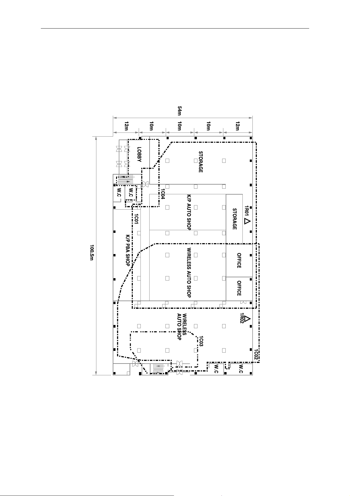
Example Cell Planning Results
Survey Map of the 1st Floor
9
Page 15
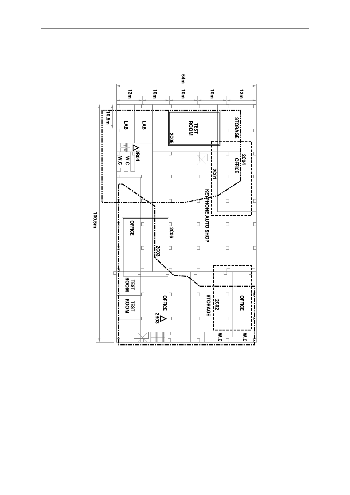
Part 1: Site Survey and Overview of DECT Systems
Survey Map of the 2nd Floor
10
Page 16
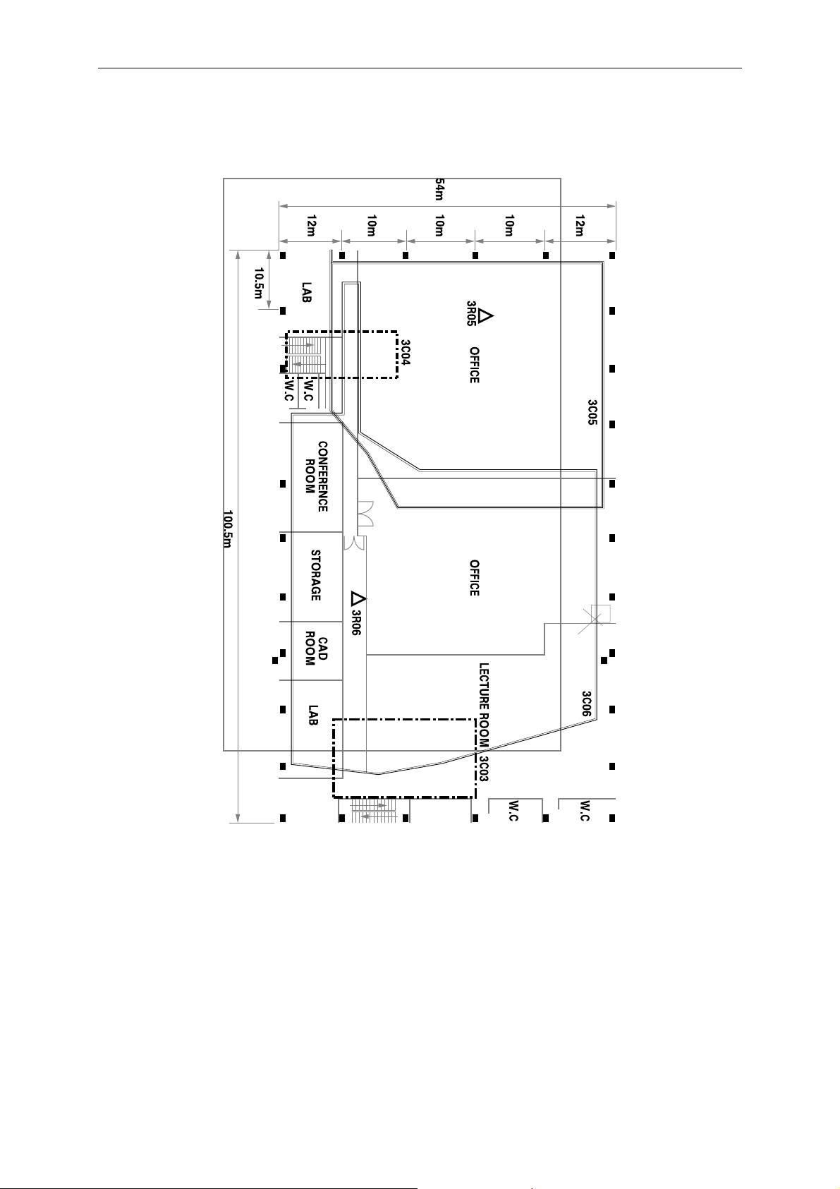
Part 1: Site Survey and Overview of DECT Systems
Survey Map of the 3rd Floor
11
Page 17
Part 1: Site Survey and Overview of DECT Systems
Positioning Base Stations
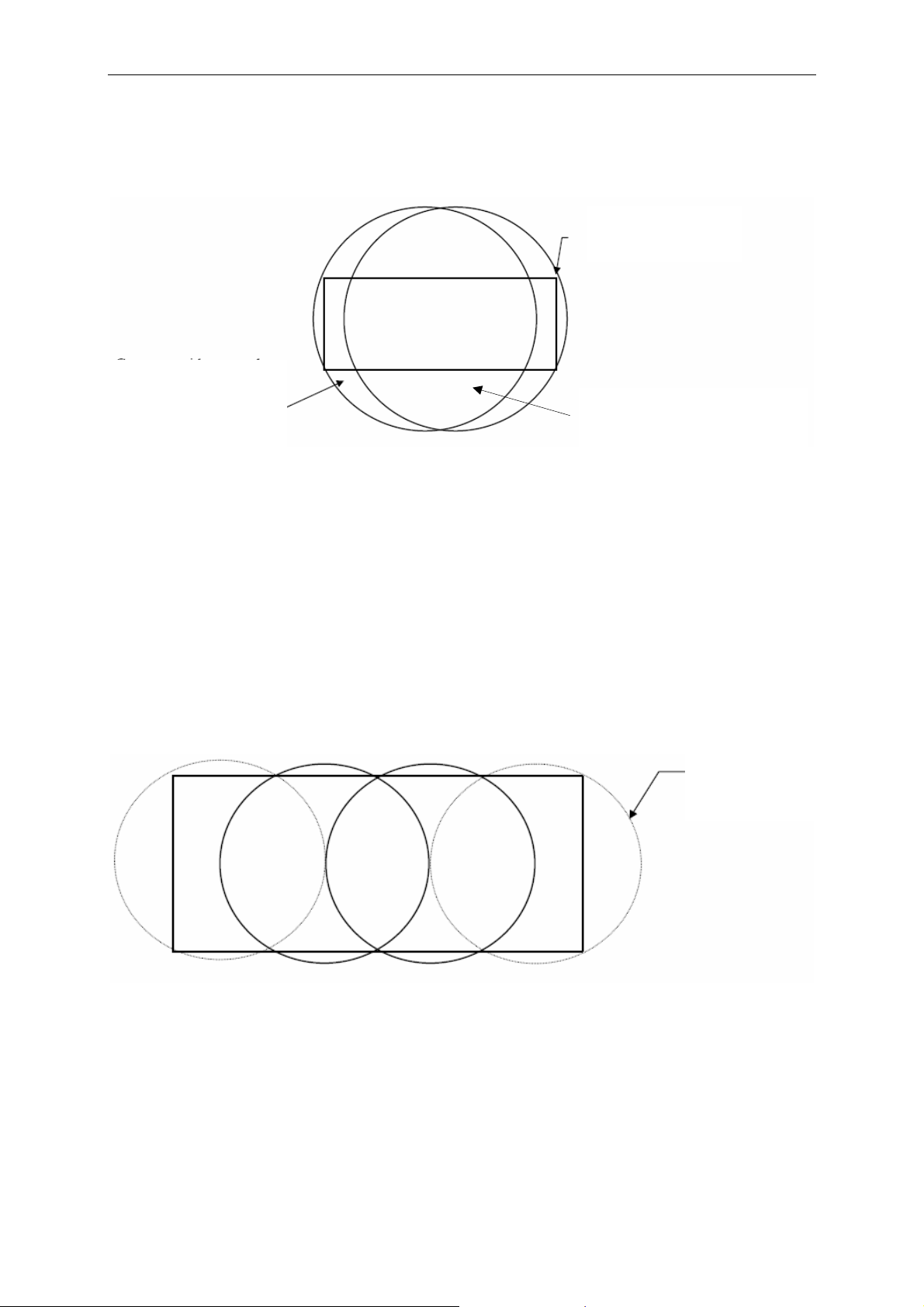
The coverage area for a Base Station within a building varies from 50 to 150 metres.
The radiation graph from a Base Station is almost circular, horizontally, when working
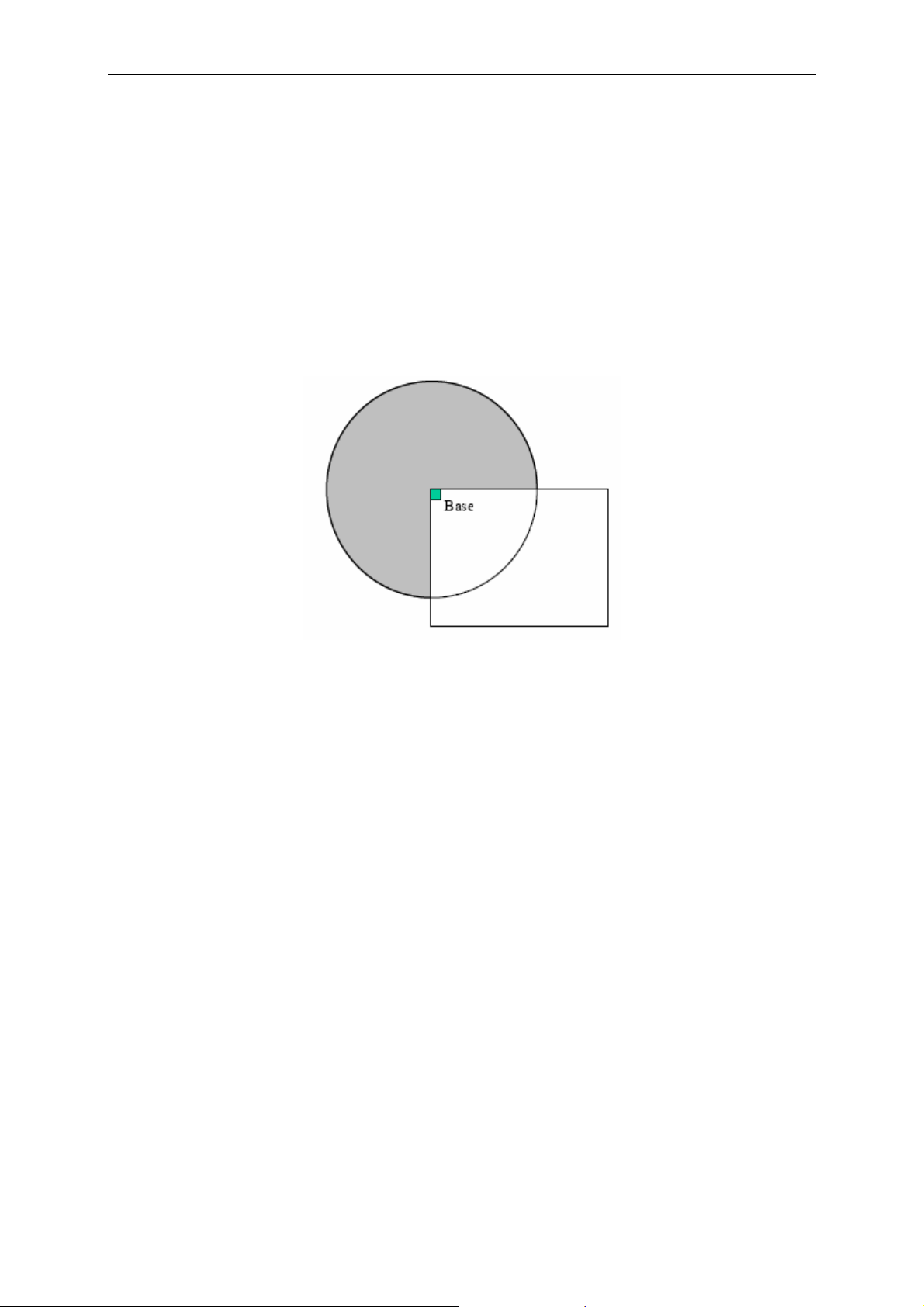
in “free” areas. If a Base Station is placed in the corner of a building, part of the coverage area is outside the building (Figure 1.1). This means that a Base Station
should not be placed in the corner of a building if the required coverage area is within
the building. The shaded area in Figure 1.1 is the “unexploited” area. In practice the
radiation graph will not be as neat as in Figure 1.1, but it is a good starting position
for planning the installation during the site survey phase.
A Base Station should be placed at a minimum height of two metres. If the Base Station is any lower, people moving around the building could affect the radio signal from
the Base Station. If the Base Station is placed too high, especially in buildings with a
steel roof, steel girders and/or large air shafts in the ceiling, there is a risk of gaps in
the coverage area. This is party due to “shadows” and/or reflections. The design of
the building, and especially equipment made of metal (shelving, racking, machinery
etc) may effect the radio signals a great deal. For example, in a warehouse where
goods are moving in and out constantly the quality of radio signals can vary from day
to day. Refer to section 1 for more information.
Figure 1.1
Using the Demonstration Base Station
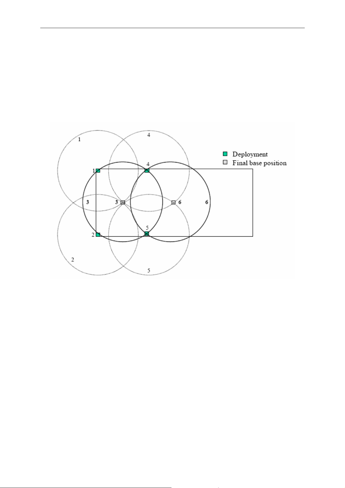
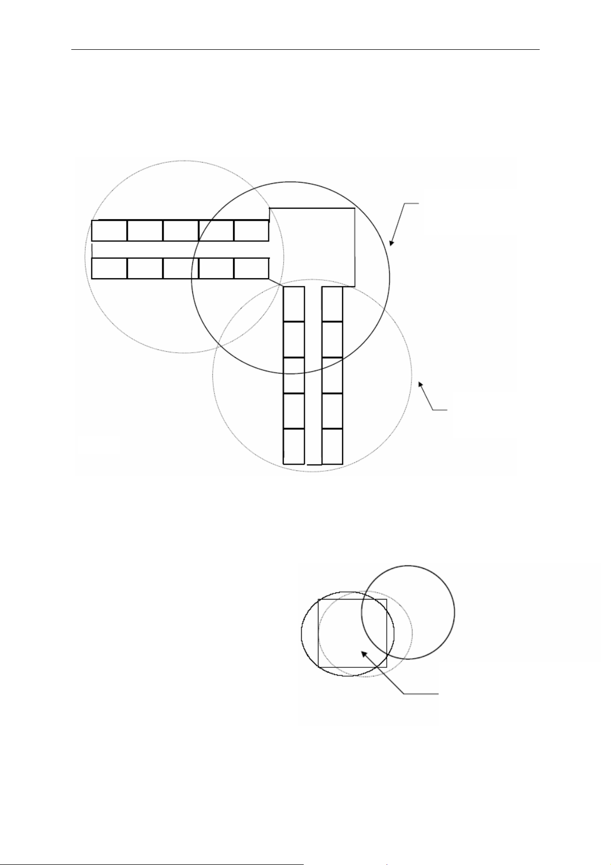
To find the correct place to locate a Base Station, the Deployment Base Station included in the DECT Demonstration and Installation Kit can be used. Refer to the example in Figure 1.2. In practice, this method will not result in a symmetric solution as
shown in Figure 1.2, but it does ensure optimum placing of the Base Stations.
A survey and demonstration Base Station is placed in the corner of the building (position 1 or 2). The broken circle indicates the coverage area to be measured for the
Base Station. The coverage of the area is defined by the fact that an RSSI value of
85dBm can be measured along the broken line.
12
Page 18
Part 1: Site Survey and Overview of DECT Systems
The RSSI value can be measured with a Samsung D-5000 handset. Note that when
carrying out measurements, the handset must be off-hook.
During measurement it is necessary to take into account the effect a human body
has on the radio signal. This is done by either holding a hand over the antenna of the
handset or by turning the handset and body away from the Base Station in a way that
causes a “worst case” scenario, i.e. a position which results in the lowest RSSI value.
Approximately RSSI 65 / Q52>54 should be measured at the broken line. The Q
value should be stable.
Figure 1.2
The permanent Base Station should be placed in the position (position 3) in which
the RSSI value is 65 and has a stable Q value of 52 from the measured survey and
the demonstration Base Station in positions 1 and 2. Then the survey and demonstration Base Station can be moved to positions 4 and 5. The measuring process can
be repeated and the permanent Base Station is placed in position 6.
Hot Spots
It is possible to have four simultaneous calls on one DECT 1500 Base Station. If the
radio coverage in an area is OK, but users require more than the allowed number of
simultaneous calls, this is called a “Hot Spot”. In a Hot Spot area, additional Base
Stations can be installed.
One or more additional Base Stations can be placed next to the existing Base Station. In this way, small overlaps between the coverage areas of the Base Stations are
avoided.
13
Page 19
Part 1: Site Survey and Overview of DECT Systems
A maximum of three Base Stations can be placed next to each other. Any more will
interrupt each other and interfere with the whole system. If there is a need for a fourth
Base Station, this must be placed at least 25 metres away.
Final Testing
The overall performance of the system can only be fully evaluated after the installation has been completed. If is necessary to move between coverage areas (cells) of
different Base Stations to conclude if the handover between Base Stations is possible. At the same time, Base Station synchronisation can be tested. This is done by
means of the test display on a handset. It will be necessary to move between the
coverage areas of the different Base Stations to determine whether a handset can
“see” the different cells.
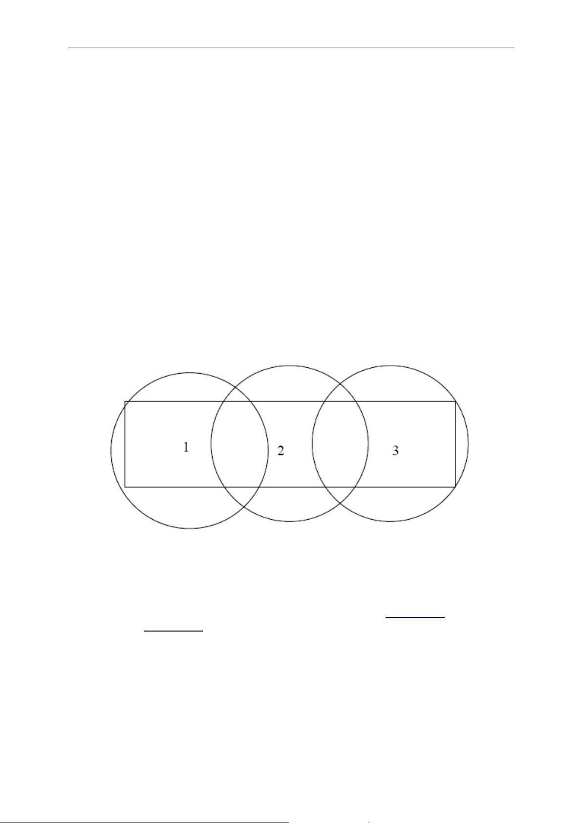
Traffic Measurement
When the cells and radio coverage are in place, the traffic must be calculated for
each cell (Figure 1.3).
Map out where handset users are typically concentrated and calculate how many
Base Stations will be required for each cell. The flowchart in Appendix 1
as a guide. In Appendix 2, some general calculations have already been made which
can also be used as a guide.
Example: How many Base Stations must be installed in a cell with 40 handsets, assuming that 1% of the time users won’t be able to make a call and each handset
makes three calls per hour and each call lasts three minutes?
Figure 1.3
can be used
14
Page 20
Part 1: Site Survey and Overview of DECT Systems
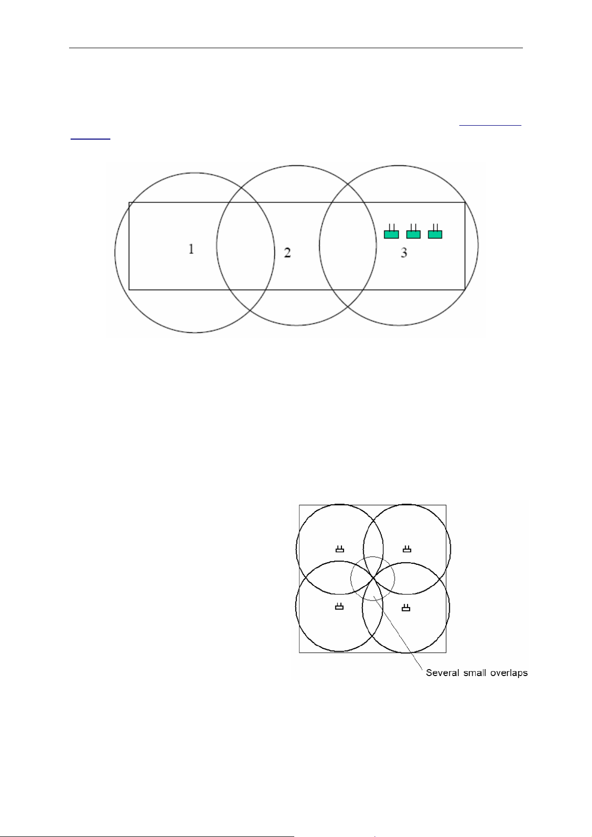
Erlang = E.
3 calls per hour, lasting 3 mins (3 calls x 3 mins)/60 min = 0.15 E
40 x 0.15 = 6 E
With 1% rejection, 6 E equals 12 channels according to the Erlang table (Appendixes
1 and 2).
A Base Station has 4 channels: 12/4 = 3 Base Stations per cell (Figure 1.4)
Figure 1.4
Troubleshooting with Base Stations
Here are some examples of situations in which problems such as lost calls, bad call
quality or not being able to go off-hook may occur.
Example 1: Several small overlap areas
If you are in an area with a lot of small
overlaps and you are moving in a given
direction, there is a risk of losing the call
because the Base Station which the
handset has as its alternative may not
necessarily be the Base Station that
you are moving towards. This can be
solved by placing a Base Station in the
middle of the area.
15
Page 21
Part 1: Site Survey and Overview of DECT Systems
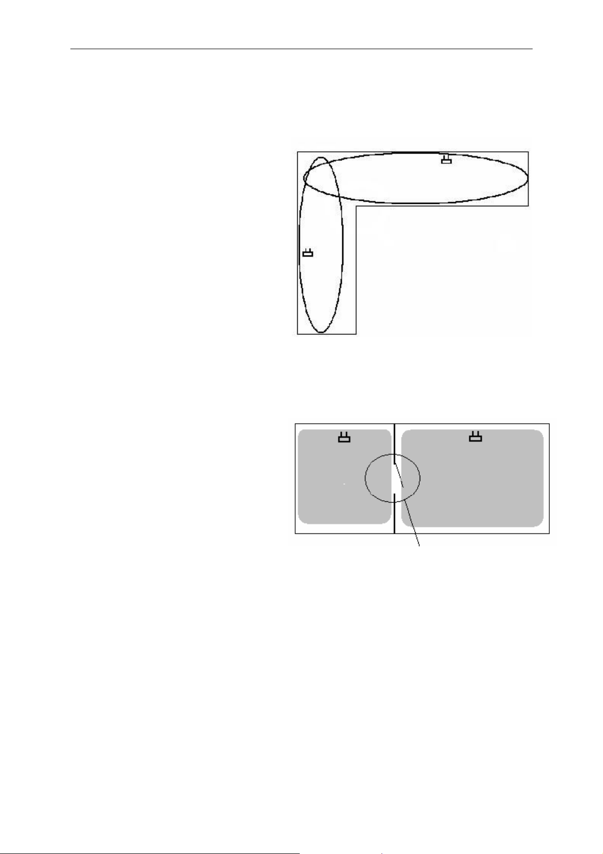
Example 2: Small overlap area
In areas where two coverage areas
meet perpendicularly (such as two
passageways), there may be an area
of very small overlap which can cause
the loss of a call. This is because you
are moving from an area with only one
Base Station to an area also with only
one Base Station. Therefore the handset does not have enough time to register to the other Base Station until you
are out of the coverage area of the first
Base Station. The problem may be
solved by moving one of the Base Stations closer to the corner point where
the two passageways meet in order to
cover both.
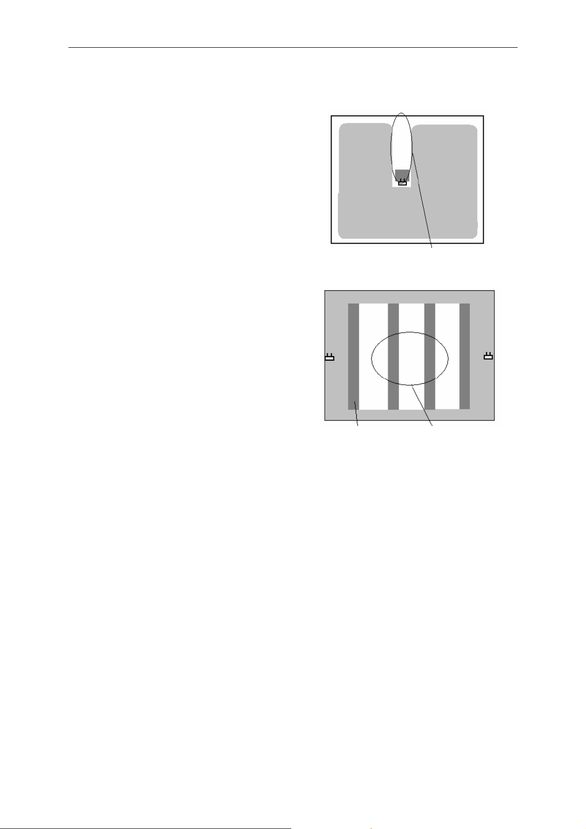
Example 3: No overlap
In areas where the coverage between
two Base Stations is separated by
steel doors or gates, the handset does
not have time to hand over and register itself to the next Base Station, thus
causing the call to be dropped. This
may be solved by moving the Base
Stations closer to each other.
No overlap when steel door or
gate is closed
16
Page 22
Part 1: Site Survey and Overview of DECT Systems
Example 4: Shadows
If Base Stations are placed on pillars of
concrete or steel (e.g. in warehouses
with steel shelves or racking), shadows
may appear with no radio coverage. This
may be solved by covering the shadow
areas with one or more additional Base
Stations.
Using Repeaters
Introduction
No radio coverage – shadow
Steel shelves/racking No coverage - shadows
A Repeater is used to extend DECT coverage. It is not a real Base Station and does
not increase the number of DECT traffic channels but it can give a larger physical
spreading of traffic channels and thereby extend the radio service of the traffic channels established with real Base Stations
The normal method of establishing multi-cell installations is to make pre-installation
site surveys to map the coverage and determine the number and location of Base
Stations. After the system is installed and tested, gaps in the coverage may be found,
or different coverage may be required, often in areas with limited traffic such as
basements, lofts or outdoor areas.
To increase the number of Base Stations requires further installation work. In such
cases the Repeater is ideal because it is not physically connected to the DECT system and, therefore, is easier to work with.
17
Page 23
Part 1: Site Survey and Overview of DECT Systems
Function of Repeaters
A Repeater can be considered as a DECT unit, comprising a DECT handset and a
Base Station in one unit that can handle up to three traffic channels. The Repeater
has the same coverage as a normal Base Station.
A Repeater must be placed within the coverage area of the existing Base Station
and, therefore, extends the coverage of the Base Station by 50% (Figure 1.5).
Repeater
Base Station
connected to the CCFP
50% increased coverage of
50% overlap
the base station
Area 1
Four Traffic Channels
Figure 1.5
Two Traffic Channels
Area 2
When there is active traffic on the Repeater, it takes traffic channels from the Base
Station. Thus, the total number of traffic channels is neither increased nor reduced
with the Repeater.
When an active handset moves from Area 1 to Area 2 (Figure 1.5), the Repeater
takes over the active traffic channel and the handset can move around within Area 2
(within the coverage of the Repeater); however, as “seen” from the Base Station the
Repeater is now the active handset. When the active handset moves back to Area 1
and outside the coverage of the Repeater, the Repeater lets go of the active channel,
gives it back to the Base Station and there is a full handover between the Repeater
and the Base Station.
18
Page 24
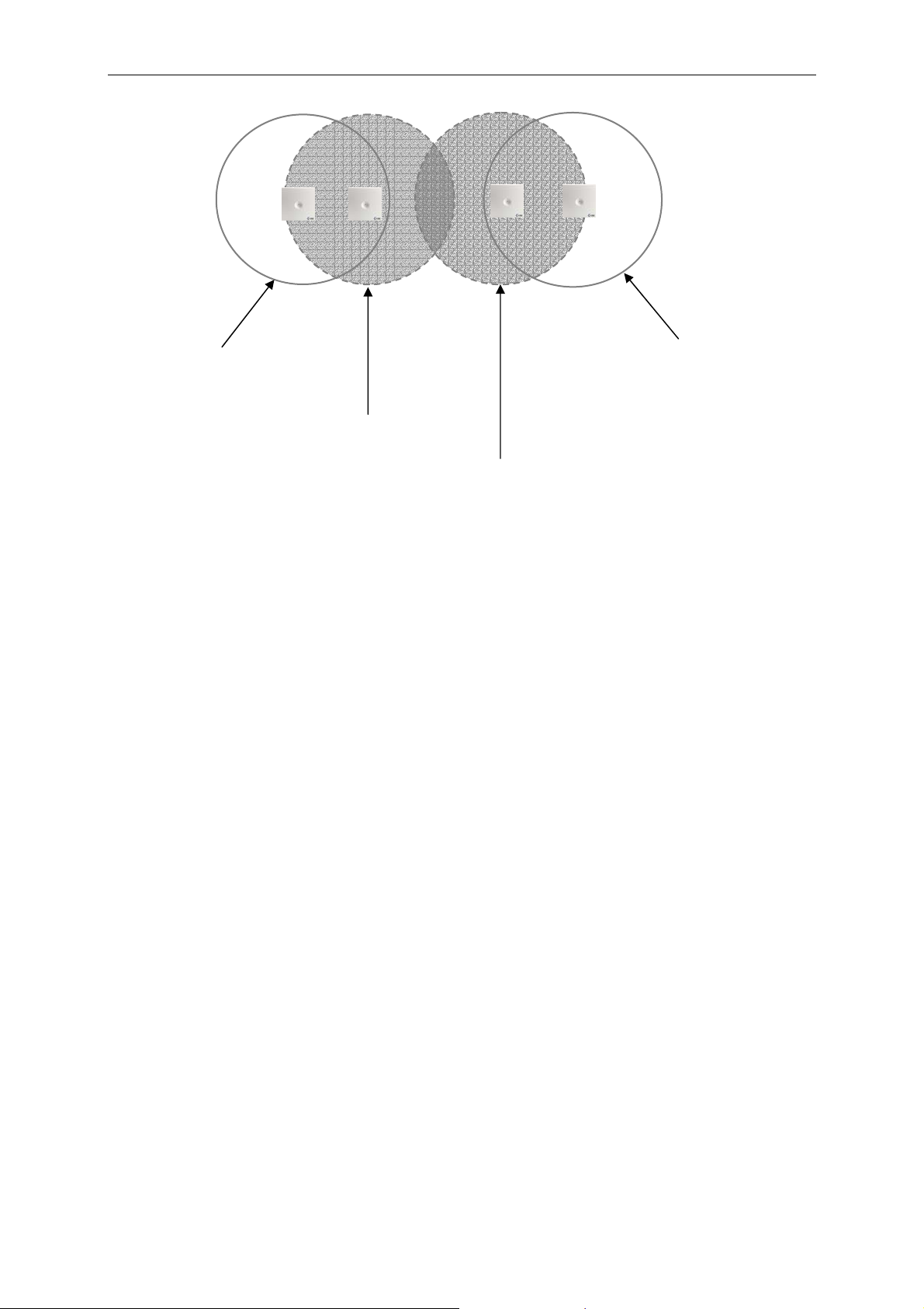
Part 1: Site Survey and Overview of DECT Systems
Base Station Area 1
Base Station Area 4
Repeater Area 2
Repeater Area 3
In Figure 1.6 an installation with two Repeaters and two Base Stations is shown. An
active handset can move from Area 1 to Area 4 without losing its call since handover
is made from the Base Station in Area 1 to the Repeater in Area 2, then to the Repeater in Area 3 and then to the Base Station in Area 4.
This means that the installation gives a wider spread of the area of traffic channels
without having to add extra channels.
Figure 1.6
Repeaters in Multi-Cell Systems
When a multi-cell system is installed, two considerations determine the number of
Base Stations:
1. Establishment of necessary radio coverage.
2. The number of traffic channels must be available to secure good performance of DECT traffic.
To fulfil point 2, under normal circumstances, one Base Station should be installed
per 10 handsets. In a busy office the system will be able to handle traffic of 0.15E per
handset registration, corresponding to an average of nine minutes per hour (approximately five calls per hour) with a blocking value of 1%
19
Page 25
Part 1: Site Survey and Overview of DECT Systems
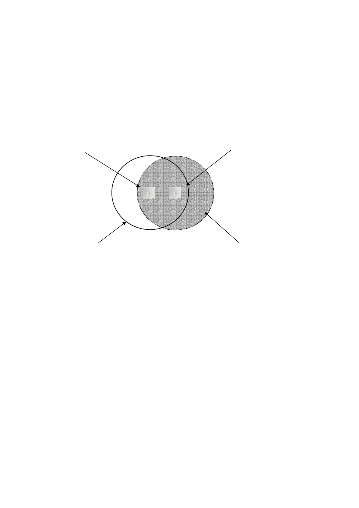
In a normal office this will not be a problem, as the coverage area of a Base Station
and the number of square metres per employee normally secures the necessary
overlap.
Office with 20 DECT
subscribers
Coverage without overlap
– traffic capacity 1E, corresponding to 6 DECT
subscribers
DECT overlap – traffic capacity
3E, corresponding to 20 DECT
subscribers
Figure 1.7
If the building is a multi-storey building with an even distribution of employees, this
rule is sufficient as the physical coverage of the Base Stations secures the necessary
overlap.
If the building is a warehouse with a large spread of employees, the Repeater can be
used to establish the necessary radio coverage, but problems with traffic capacity
may arise.
Repeater coverage
– traffic capacity
0.15E
Figure 1.8
The traffic capacity in the Repeater area is only 0.15E, which does not mean that
there can only be one active handset in the area. The Repeater can handle two traffic
channels and therefore two simultaneous calls and the probability that the Repeater
is busy with traffic for two handsets (0.15 + 0.15 = 0.3E) is more than 1% (actually
3%) and therefore there will be no even distribution of traffic.
20
Page 26

Part 1: Site Survey and Overview of DECT Systems
Repeater coverage
– traffic capacity
0.15E
Room with few
employees
Figure 1.9
If the Repeater is used to obtain coverage in areas of low traffic, i.e. areas with few
employees with DECT handsets, the Repeater can be used as shown in Figure 1.9.
Another possibility is to install two Repeaters in the outer areas, giving an even distribution of traffic capacity. However, such a solution may be more expensive than
establishing coverage with real Base Stations as the traffic capacity increased.
The Repeater can only be used to a limited extent as a substitute for a real Base Station since the Repeater does not increase the traffic capacity. Therefore, the correct
procedure to installing a DECT system is to establish coverage of the primary areas
with real Base Stations and use Repeaters in areas where the radio coverage is
wanted, but where the traffic intensity is low.
Areas with Low Traffic Intensity
The Repeater can be used to establish coverage in areas with low traffic intensity.
This could be a passageway between DECT areas or coverage outdoors (Figure
1.10).
Passage
Repeater
Parking area
Figure 1.10
21
Page 27
Part 1: Site Survey and Overview of DECT Systems
Figure 1.11 demonstrates a hotel installation where the radio coverage is established
by registering two Repeaters on the same Base Station. The Base Stations are
placed in the area where the highest traffic intensity may occur. This can be repeated
on each floor and thus create the radio coverage with a relatively small number of
Base Stations compared to the area of the building.
Base Station– traffic
capacity 1E
Figure 1.11
Displacement of Traffic Capacity Using Repeaters
In multi-cell installations it may be
necessary to establish high traffic
areas, depending on working conditions and movement patterns. An
example would be a meeting room or
canteen. The task can be achieved by
installing more Base Stations covering
the same area and increasing the
channels. Another solution is to move
traffic channels from an adjoining Base
Station, so that the capacity is
available when needed rather than all
the time.
Figure 1.12
Area covered by Base
Station and Repeater
Total of 6 traffic channels
Repeater– traffic
capacity 0.15E
22
Page 28

Part 1: Site Survey and Overview of DECT Systems
Repeaters as Problem Solvers in Multi-Cell Systems
Typical problems with multi-cell systems are:
• Missing radio coverage
• Missing traffic capacity
One of the typical problems is lack of coverage even after the site survey showed no
problems. This could be because in multi-cell systems some of the cells may interfere with each other; the Base Station may not have been installed in exactly the
same location as the survey Base Station during the site survey; or when the building
is busy (especially in the case of warehouses) shelving, racking and stored goods
may influence the radio coverage.
The radio coverage is not the same all year, as coverage may depend on humidity or
building material. Therefore, a DECT system must be installed with a security overlap
between coverage areas which can cause a rise in overall installation costs.
Repeaters are excellent tools for adjusting multi-cell installations: they are easy to
install and move, as they need no cabling.
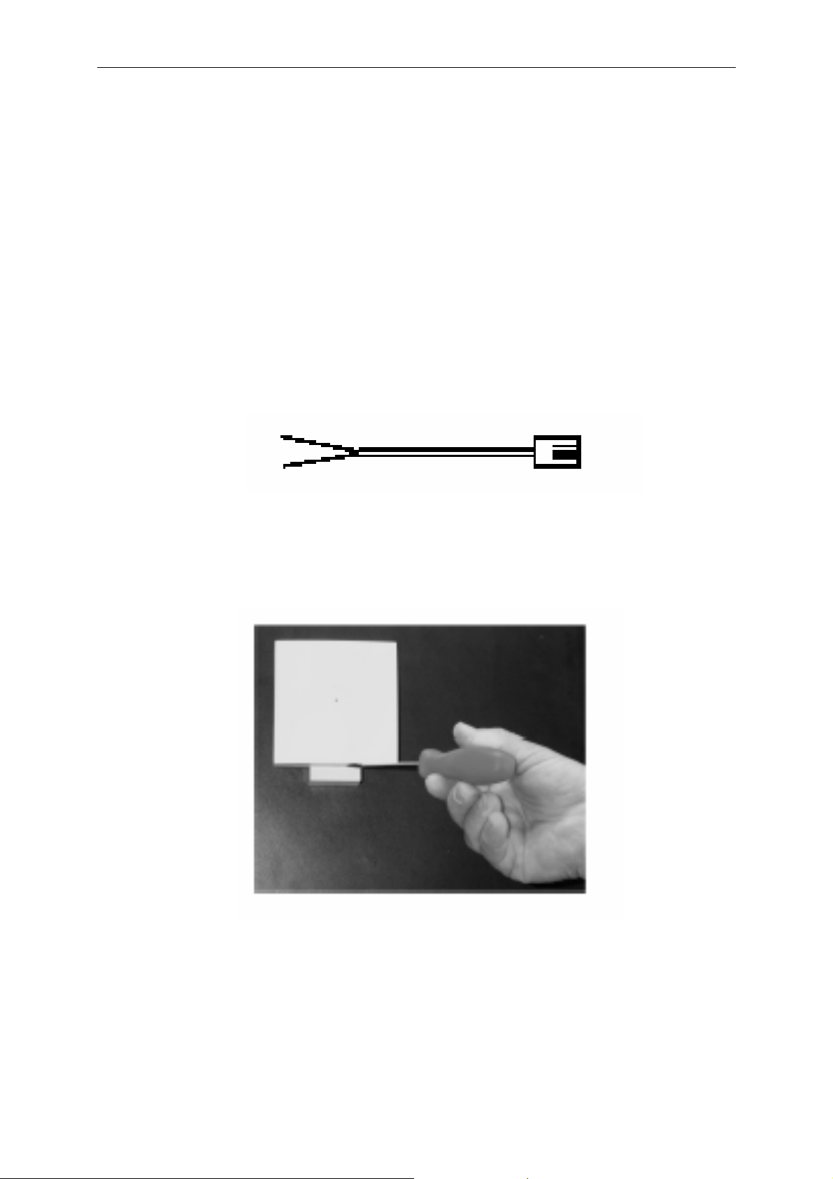
Installation of Repeaters with External Directional Antenna
The Repeater can be installed with an external directional antenna so it can be used
to create radio coverage in a remote building or area (Figure 1.13). With a standard
antenna, coverage can be extended to a distance of around 1,000 metres, but this
may be greater or less if a higher or lower gain antenna is used. This is useful where
cabling is not possible or too expensive to install (Figure 1.14).
When the Repeater does not have to hand over, the Repeater can be programmed to
repeat up to three traffic channels.
Figure 1.13
23
Page 29

Part 1: Site Survey and Overview of DECT Systems
Distance: approx. 1,000 metres
Figure 1.14
Repeater Jumps
Repeaters can be linked together in a chain of up to three. In this way a large cell can
be created. In Figure 1.15 a configuration is shown with an external antenna on the
first Repeater.
There are only two traffic channels in the Repeater-covered area as there must be
space for any handovers.
This configuration can be used to expand the coverage area of a Repeater installation, but only in areas with very low traffic demand as the total area will have to share
two traffic channels.
External antenna
Repeater jump:
traffic 0.15E
Figure 1.15
24
Page 30

Part 2: DECT Hardware Installation
(
and Programming
DECT 1500 System
Hardware Configuration Overview
The DECT 1500 system is an “add on” to existing or new PABX installations. The
system can handle up to 64 cordless handsets.
It comprises a Central Control Fixed Part (CCFP), up to 16 Radio Fixed Parts (RFP
or Base Stations) and Portable Parts (PP, handsets). It may also include up to three
Repeaters (WRFP) per Base Station (i.e. up to 48 per system). A PC is also connected to the CCFP via the RS-232 serial port for configuring the system using the
administration program.
RFP (Base Station)
DECT 1500
PABX
Up to 64 Handsets
Figure 2.1 DECT 1500 System
SIO
WRFP
PC
Repeater)
25
Page 31

Part 2: DECT Hardware Installation & Programming
Configuring the CCFP
The CCFP comprises a power supply and a main board. One expansion board, a
Link card and up to eight Inter-Working Units (IWUs) can be mounted in the CCFP in
slots 0–7 (Figure 2.2). There are three extra slots 8–10.
• One IWU A8 handles eight analogue telephone lines for eight handsets. Eight
IWUs are therefore required for 64 handsets.
• The main board handles eight RFPs. The expansion board is required if more
than eight RFPs are needed. The number of RFPs depends on the traffic density and the coverage area.
• One RFP can handle four simultaneous handsets calls.
• The Link card is used to connect two 1500 systems together. It installs in slot
10 of the extra slots. A combined system increases the number of Base Stations to a possible 32 and Repeaters to a possible 96.
• Extra slots 8 and 9 are not used.
Figure 2.2 The CCFP
26
Page 32
Part 2: DECT Hardware Installation & Programming
Installing the Expansion Board and IWUs
The CCFP expansion board has to be mounted in the CCFP if more than eight RFPs
are needed. The expansion board handles up to eight RFPs besides the eight RFPs
the CCFP main board handles (maximum 16 RFPs).
The CCFP needs the FLASH software PCS3 or later edition to control the expansion
board. If the CCFP has an older software version it is necessary to upgrade the system. Upgrade software is not included in expansion kit (PN 13816).
1. Disconnect the CCFP from its power supply.
2. Remove the top cover.
3. Remove the blind cover plates.
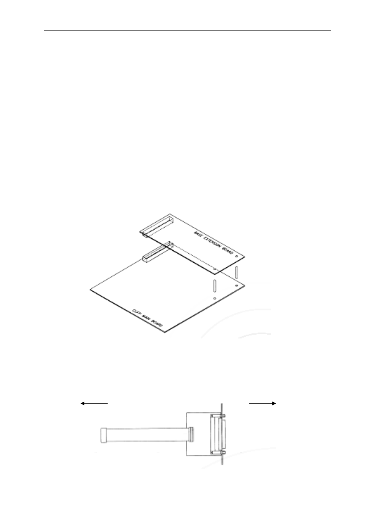
4. Mount the expansion board on the CCFP by inserting the two plastic pins (Figures
2.2 and 2.3).
5. Insert the IWUs starting at slot no. 0 (Figure 2.2).
Figure 2.3 Mounting Expansion Board
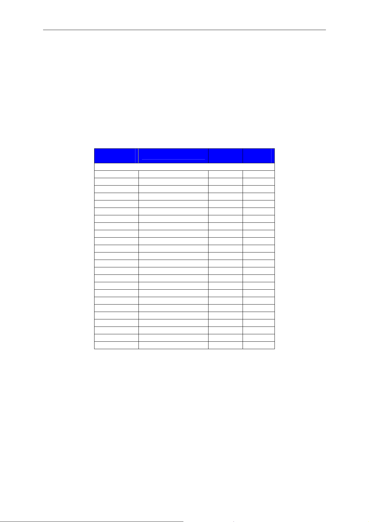
5. Mount the expansion board internal cable in place of the blind covers (Figure 2.4).
Expansion Board Rear Panel
Figure 2.4 Internal Cable
27
Page 33
Part 2: DECT Hardware Installation and Programming
6. Replace the top cover.
7. Connect the RFPs or the PBX extension lines to the DP 25 connectors.
8. Power up the CCFP.
If the RFPs are installed, make a cable measurement.
Cable Connections
RFPs (Base Stations)
D-Sub Pin
No.
1 WHITE/BLUE 0A 8A
14 BLUE/WHITE 0B 8B
2 WHITE/ORANGE 1A 9A
15 ORANGE/WHITE 1B 9B
3 WHITE/GREEN 2A 10A
16 GREEN/WHITE 2B 10B
4 WHITE/BROWN 3A 11A
17 BROWN/WHITE 3B 11B
5 WHITE/SLATE 4A 12A
18 SLATE/WHITE 4B 12B
6 RED/BLUE 5A 13A
19 BLUE/RED 5B 13B
7 RED/ORANGE 6A 14A
20 ORANGE/RED 6B 14B
8 RED/GREEN 7A 15A
21 GREEN/RED 7B 15B
9 RED/BROWN NC NC
22 BROWN/RED NC NC
10 RED/SLATE NC NC
23 SLATE/RED NC NC
11 BLACK/BLUE NC NC
24 BLUE/BLACK NC NC
12 BLACK/ORANGE NC NC
25 ORANGE/BLACK NC NC
Cable Colour
Base
Conn 0
Base
Conn 1
28
Page 34
Part 2: DECT Hardware Installation and Programming
Analogue Telephone Extensions
Extensions connect to the IWUs.
D-Sub Pin
No.
EE
14 WHITE/BLUE 0A
1 BLUE/WHITE 0B
15 WHITE/ORANGE 1A
3 ORANGE/WHITE 1B
2 RED/SLATE 0 EARTH
16 BLACK/ORANGE 1 EARTH
17 WHITE/GREEN 2A
4 GREEN/WHITE 2B
18 WHITE/BROWN 3A
6 BROWM/WHITE 3B
5 SLATE/RED 2 EARTH
19 ORANGE/BLACK 3 EARTH
20 WHITE/SLATE 4A
7 SLATE/WHITE 4B
21 RED/BLUE 5A
9 BLUE/RED 5B
8 BLACK/BLUE 4 EARTH
22 RED/BROWN 5 EARTH
23 RED/ORANGE 6A
10 ORANGE/RED 6B
24 RED/GREEN 7A
12 GREEN/RED 7B
11 BLUE/BLACK 6 EARTH
25 BROWN/RED 7 EARTH
Cable Colour IWU Line
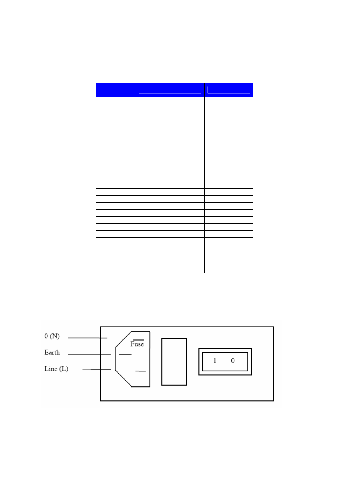
Power Connection
Figure 2.5 Power Connection
29
Page 35
Part 2: DECT Hardware Installation & Programming
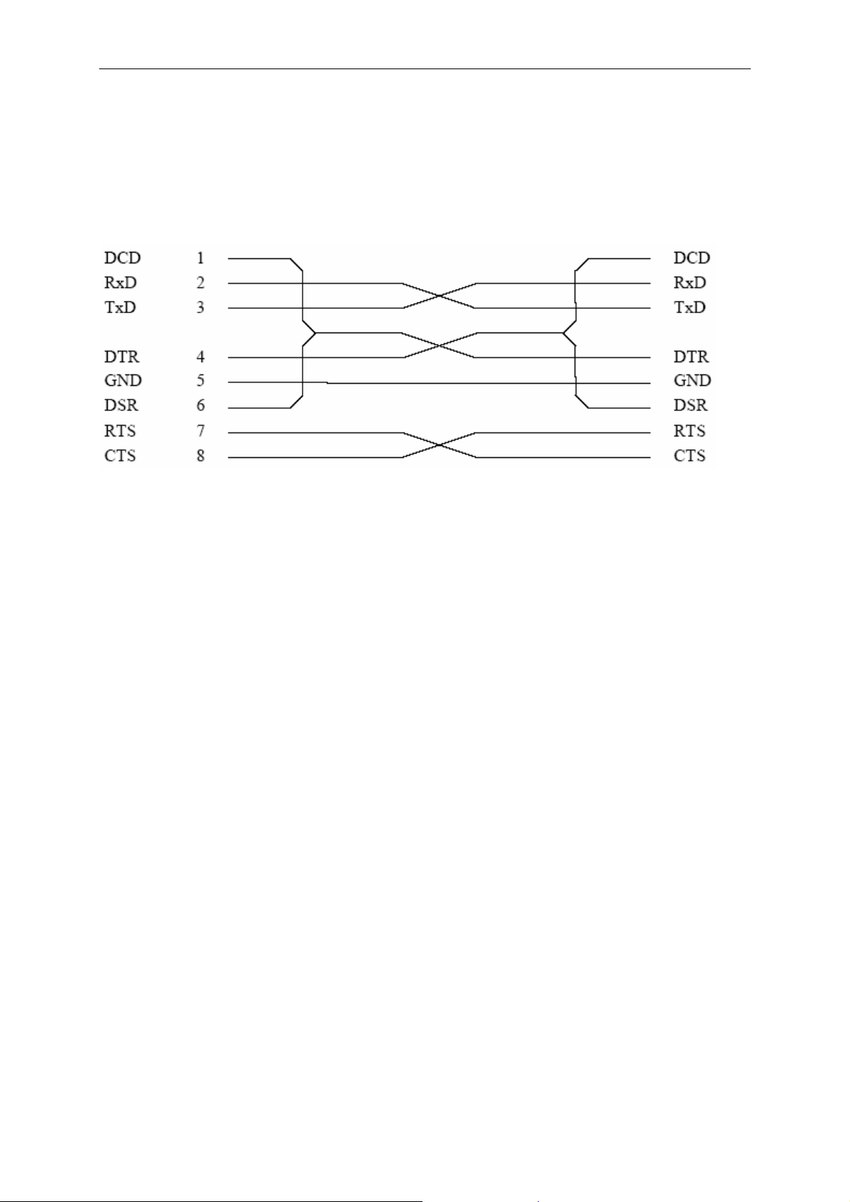
Serial Connection
The serial port is a 9-pin D-SUB male type. When connecting a PC to the CCFP, a
full connection DTE-DTE must be used (Figure 2.6).
Figure 2.6 Serial Connection
Installing the CCFP
When mounting the CCFP on a wall it is important that the supplied bracket is used.
If is also important to make allowance for accessing the connecting cables via the
base of the unit.
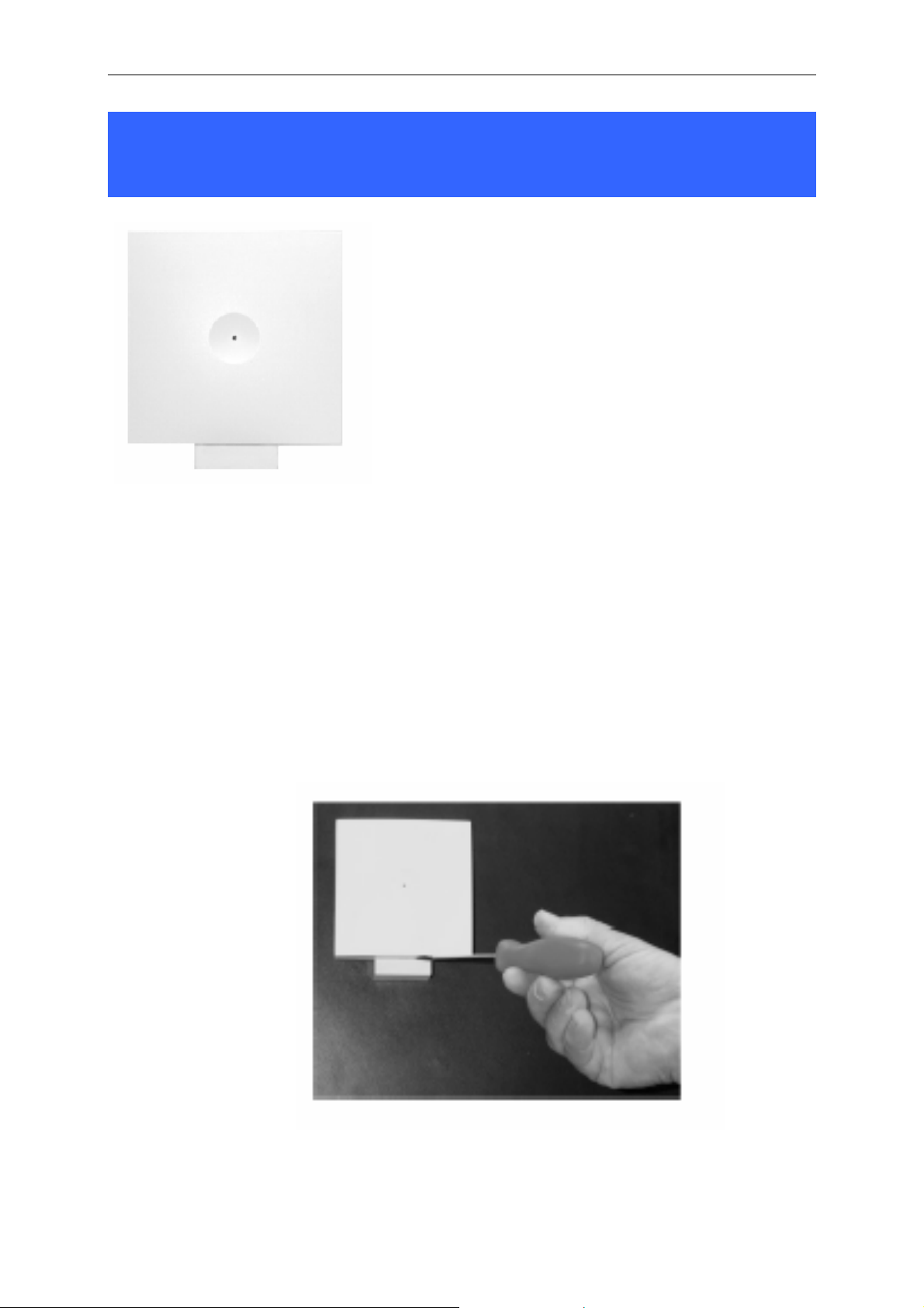
Installing RFPs (Base Stations)
Overview
The Radio Fixed Part (RFP) is designed with two internal antennas and supports antenna diversity. The RFP can also carry out a handover between the RF channels
under the same RFP, and handles four DECT speech channels simultaneously. The
RFP is able to frame synchronise with other RFPs under the same CCFP.
Transmission length is up to 2 km on 0.5mm twisted pair, e.g. cat.4, between the
RFP and CCFP. The RFP is also supplied with power from this connection (maximum supply 1.5 W). The DECT radius of coverage is up to 600 metres with a handset in free sight. It is possible to connect a maximum of eight RFPs to a CCFP without an expansion board, 16 RFPs with an expansion board and 32 with a link system
(using the Link card to connect two systems).
30
Page 36
Part 2: DECT Hardware Installation and Programming
Installation
First determine where to install the RFP to have the correct coverage. The average
coverage within buildings is 75 metres. Coverage depends on the construction of the
building, the architecture and choice of buildings materials. You must use the DECT
Demonstration and Installation Kit to optimize your installation. This deployment tool
consists of an RFP which has no need for a CCFP. It can easily be moved around in
the building and one to eight handsets can be connected.
1. Pull the a/b wire from your installation through the wall holder and then mount
the wall holder on the wall.
2. Connect the a/b wire to the plug on the back of the RFP. Use pins 3 and 4 on
the RJ-11 connector.
3. Ensure the RFP is the right way up and “click” it onto the wall holder.
If you need to remove the base station, separate it from the wall holder with a gentle
push of a screwdriver.
31
Page 37

Part 2: DECT Hardware Installation & Programming
Starting the DECT 1500 System
1. Install the CCFP administration software on an IBM-compatible PC.
2. Make sure that all RFPs are connected correctly. Also, make sure that all IWU
connections are made to PABX lines.
3. Connect a serial cable (RS-232) between the CCFP and the PC installed with
the administration software.
4. Connect the power cable to the CCFP. Ensure that there is an earth connection in the power supply plug.
5. Power up the CCFP.
6. Use the administration program to:
• Configure the system.
• Make a cable measurement to all installed RFPs.
• Adjust IWU parameters as required.
• Register each handset to the system.
32
Page 38

Part 2: DECT Hardware Installation and Programming
DECT 500 System
Hardware Configuration Overview
The DECT 500 system is an “add on” to existing or new PABX installations. The system can handle up to eight cordless handsets.
It comprises a Base Station/Control Unit (CCFP) and a number of Portable Parts
(PP, handsets). It may also include up to six Repeaters (WRFP). The RS-232 connector can be used to connect a PC or a modem for programming, etc.
PSTN lines
PABX
• The Base Station/Control Unit
(CCFP) is placed strategically
for optimal coverage and where
traffic channels are needed
8 a/b lines
RS-232
(PC, Modem,
MSF, etc.)
Base Station
• Connect up to
8 handsets
Figure 2.7 DECT 500 System
The Base Station supports six simultaneous handset calls.
• 6 repeaters can be con-
nected to increase radio
coverage
Repeater
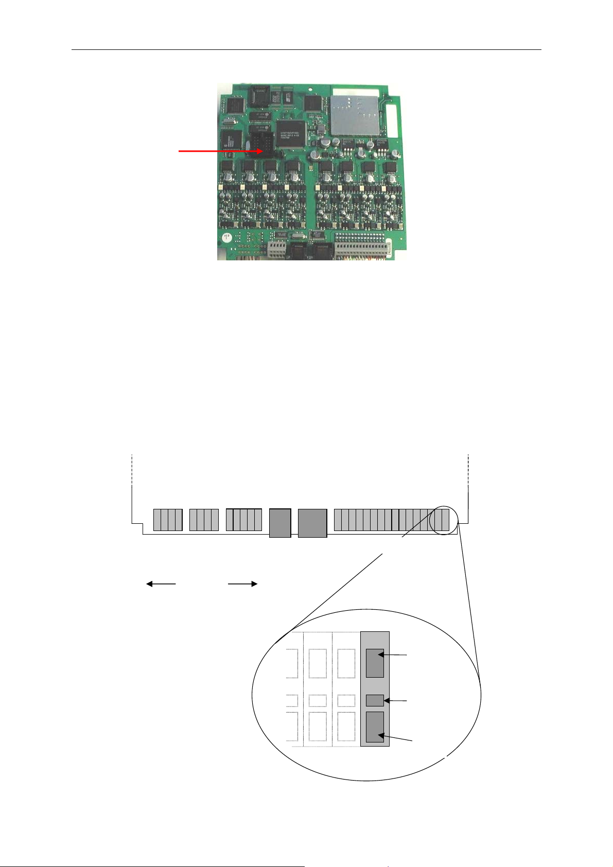
Setting Optional Password Protection
An optional password protection feature can be enabled which requires a password
to be entered before the administration program can be accessed. The feature is disabled by default by a plastic jumper mounted on the ALT connector on the CCFP
main board (Figure 2.8).
To enable password protection, remove the jumper from the connector and set a
password using the administration program.
33
Page 39
Part 2: DECT Hardware Installation & Programming
ALT
Connector
Figure 2.8 Selecting Password Protection
Installing the Base Station/Control Unit (CCFP)
The Base Station/Control Unit may be located up to 1km from the PABX, connected
via a standard 0.5mm twisted pair cable.
Connections
AUXIN1
GND1
AUXIN2
AUXOUT1
GND1
AUXOUT2
GND1
GND1
RX-
RX+
NCNCGND
TX-
TX+
GND
NC
DSR
NC
9V
DCD
RXD
2*Aux
2 * Aux 2 * Aux RS422 9V DC RS-232
Output
Output Input
Input
Future optional
interfaces
For Future
Use
Tip
ring
tip
ring
tip
ring
tip
ring
tip
ring
tip
ring
tip
ring
tip
RTS
CTS
GND
Line 0
line 1
line 2
line 3
line 4
TXD
DTR
16*A/BRS232RS422 9V dc2*Aux
16 * a/b
line 5
ring
line 6
line 7
Hole 1
Hole 2
Hole 3
34
Page 40

Part 2: DECT Hardware Installation and Programming
Starting the DECT 500 System
When you are ready to begin using the system and register handsets, switch the
power on at the mains.
When operational, the status of the DECT system is shown by the LED display.
• Steady red and green means there is a fault, or it is in flash programming mode. (If
faulty, power up the system with the ‘Boot Strap’ jumper mounted on the main
board.)
• Fast flashing red means the system is not programmed and Master handset sub-
scription is not allowed.
• Fast flashing green means the system is not programmed and Master handset
subscription is allowed.
• Slow flashing red means it is in operation with the maximum active connections
(busy).
• Slow flashing green means it is in operation with active connections.
• Steady green means it is in operation and ready for use with no active connec-
tions.
Registering Handsets
Registering a Master Handset
When switched on, the DECT 500 system will automatically go into registration mode
for a period of 15 minutes. During this period you can register the Master handset.
This handset is automatically configured to channel 00.
NOTE: it is only possible to log in one Master on each system. The first handset is automatically the
Master handset.
1. Switch on the handset.
2. Press the MENU key.
3. Press the < key and go to MENU LOGIN.
4. Press the OK key and go to SUBSCRIPTION CREATE.
5. Press the OK key.
35
Page 41

Part 2: DECT Hardware Installation and Programming
The handset will start searching for your system. When the handset finds a
system, a number will appear in the display. The handset may detect more
than one system (another system nearby); if so, a black triangle will appear in
the bottom of the display.
6. Scroll through the numbers in the display by pressing the < or the > key to find
your system’s number. It is important that the number shown in the display is
identical to the number on your system. The number is indicated as an ARI
(on the label on the back of the base station).
7. When you have selected the correct number, press the OK key and the handset will be configured as the Master handset for the system.
Now you must allocate an extension number to the handset.
1. Press the MENU key and go to EXT SERVICE.
2. Press the OK key and go to READ/WRITE USERDATA.
3. Press the OK key.
The serial number of the Master handset shows in the display.
4. Press the OK key.
The handset asks for an extension number.
5. Enter the extension number. This can be the existing extension number for the
corded phone being paired with the handset, or any number available in the
PABX if the handset is being used as the only phone.
6. Press the OK key.
7. Switch the handset off and on again: the extension number is displayed.
Referring to this handset as the ‘Master’ means that you can configure more handsets in the system using this handset, as described next.
Registering Additional Handsets via the Master Handset
To register a handset, the Master handset must "allow" you to do so. Each handset
registered is configured to a channel 01 to 07.
1. Press the MENU key and go to EXT SERVICE.
2. Press the OK key and go to READ/WRITE USERDATA.
3. Press the OK key.
36
Page 42

Part 2: DECT Hardware Installation and Programming
The Serial Number of the Master handset (channel 00) is displayed.
4. Press the > key and enter the serial number of the new handset (found inside
the handset on the label under the battery).
The handset is registered to channel 01.
5. Press the OK key.
The handset asks for an extens ion number.
6. Enter the extension number. This can be the existing extension number for the
corded phone being paired with the handset, or any number available in the
PABX if the handset is being used as the only phone.
7. Press the OK key.
The new handset is now registered in the system. To register more handsets, press
the < key to return to the registration menu and follow the same procedure.
Deleting a Registered Handset
To delete the Master handset, use the CCFP administration program. To delete an
additional handset, either use the administration program or follow this procedure:
1. Press the MENU key and go to EXT SERVICE.
2. Press the OK key and go to DELETE USERDATA.
3. Press the OK key.
The Serial Number of the Master handset (channel 00) is displayed.
4. Select the number of the handset (Master or additional) to delete.
5. Press the OK key.
37
Page 43
Part 2: DECT Hardware Installation and Programming
Installing and Configuring a Samsung Repeater (WRFP)
Although Repeaters look similar for both the
500 and the 1500 system, they are not interchangeable. Do not attempt to use a Repeater
intended for a 500 system on a 1500 system, or
vice versa.
To install a Samsung Repeater, it is recommended you use the instructions in part A. If
you do not have access to the Repeater / Hand-
set Programming Tool (PN 13821) and a PC, use
the instructions in part B.
A.
You will need the Repeater / Handset Programming Tool running on a PC connected
to the DECT system and documentation on how to connect the cables.
1. Pull the wire from the power supply through the wall holder and then mount
the wall holder on the wall.
2. Connect the wire to the plug on the back of the Repeater and "click" the
WRFP onto the wall holder.
If you need to remove the Repeater, separate it from the wall holder with a gentle
push of a screwdriver.
To configure the Repeater, run the Repeater / Handset Programming Tool.
38
Page 44

Part 2: DECT Hardware Installation and Programming
B.
(NOTE: For the DECT 500, please disregard point 3.)
1. Switch on the Base Station (RFP) and a registered handset.
2. Switch on the Repeater for more than one second and less than five seconds
(see note 1). Switch off the Repeater and switch it on again.
The Repeater is now in “subscription” mode. This is indicated by a flashing
LED immediately after power is switched on. In this mode the Repeater is
searching for a Base Station. This mode is active for a maximum of five minutes. (If the subscription procedure is not completed within this time, the Repeater restarts in normal mode with previous data.)
3. Start subscription mode in the Base Station. The usual procedure is to press
the button on the Base Station for several seconds. This is the mode normally
used when registering a handset to the Base Station (see note 2).
The Repeater is synchronised with the Base Station in subscription mode. This
is indicated by a fast flashing LED.
4. Verify that the Repeater is synchronised with the requested Base Station.
Press the Hook-key or INT-key on the handset. The LED on the Repeater
(visible through the “keyhole” on the back) should light steady. If the LED does
not light after pressing the Hook-key or INT-key a few times, the Repeater is
probably synchronised with another Base Station: if this is the case, the subscription procedure should be repeated from step 2.
5. Select the Radio Part Number (RPN). Hook off and press a number on the
handset in the range 2–7. When the number is accepted by the Repeater, this
is acknowledged by the LED flashing the number of times corresponding to the
digit pressed. Digits may be entered several times. Only the last accepted digit
is recorded (see note 3
Station, they must have different RPNs.
6. Accept subscription identities by hook off and pressing the * key. When the key
is accepted by the Repeater the LED indicates that the key is turned off for two
seconds. Alternatively, the subscription can be accepted by pressing the # key
(see note 4).
The Repeater now restarts with the new subscription identities in normal mode.
The LED lights steady for five seconds and the Repeater is then ready to use.
Note 1: In normal operation mode the LED will lig ht steady for the first five seconds after powering up. Afterwards, the LED flashes when the Repeater is unsynchronised a nd becomes steady when synchronised to a
base station. Whenever a connection is established via the Repeater, a short flash occurs on the LED.
Note 2: Subscription mode is indicated by broadcasting DECT FP-Capabilities (bit a44=1).
). If you are using more Repeaters on the same Base
39
Page 45

Part 2: DECT Hardware Installation and Programming
Note 3: When the base station is a residential sing le cell base station, the valid RPN is in the range 2–7.
When the Repeater is used on a PABX or public system, the R PN may be in the range 0–255. In this case,
the Repeater accepts up to three digits entered. The last three valid digits only are recorded.
Note 4: If the #-key is used to accept the subscription identities, an inspection tone is enabled. The Repeate r
will then, when relaying connections, insert a short tone every two seconds in the audio path to handsets.
This feature can be used for inspection and verifica tion of the Repeater place ment. When the operation has
been verified, the inspection tone should be dis abled. Performing step 2 only of the subscription procedure
will disable the inspection tone. When the LED has started flashing in su bscription mode, switch off the Repeater and then on again. The Repeater is then back in normal mode without affecting the subscription identities and the inspection tone has been disabled.
40
Page 46

Appendix 1: Deployment Flowchart
41
Page 47

Appendix 2: Traffic Calculations
NOTE: The table of figures is intended as a guide only.
Number of DECT RFP
1 4 1 7
2 8 3 20
3 12 6 40
4 16 9 60
5 20 12.6 84
6 24 16 107
Number of DECT
channels
Traffic in E with 1%
busy/rejection
Number of
PP/handsets 0.15E
7 28 19 127
8 32 22 147
9 36 26 173
10 40 30 200
11 44 33.7 225
12 48 37 247
13 52 41 273
14 56 44.7 298
15 60 48 320
16 64 52 347
42
Page 48

Samsung Telecoms (U.K.) Limited
Brookside Business Park, Greengate, Middleton, Manchester M24 1GS
 Loading...