

Page 1

TECHNICAL MANUAL
UPDATE
July, 2001
Dear Dealer,
This DCS 50si Technical Manual Update includes information on the new FALCON
keyset family.
Please add or replace the following material:
1. General Description Section
- Replace the existing section by printing the 50_gd.pdf file contained in the CD.
2. User Instructions Section
- New Table of Contents and modified pages 1.1—1.22.
- New Falcon Keyset User Guide.
- Please keep your existing DCS 50si Keyset User Guide, DCS 50si Standard Telephone
User Guide, DCS 50si System Administration and Special Features Guide and DCS 50si
Auto Attendant and Uniform Call Distribution Administration Guide.
3. Installation Section
- New Table of Contents.
- Modified Part 6. Connecting Station Equipment.
- Remove Figures 6-15, 6-16, 6-17 and 6-18. Replace with the following figures:
6-15A, 6-15B, 6-16, 6-17, 6-18, and 6-19.
4. Programming Section
- Modified MMCs: 104, 106, 116, 209, 213, 315, 404, 405, 602, 706, 714, 715, 722,
723, 725, 728.
- Modified Datasheets: 107 and 722&723.
Thank you.
Page 2

DCS 50si USER INSTRUCTIONS
TECHNICAL MANUAL TABLE OF CONTENTS JUNE 2001
TABLE OF CONTENTS
USER INSTRUCTIONS SECTION
PART DESCRIPTION PAGE
1 ENHANCED DISPLAY PROGRAMMING
1.1 OVERVIEW........................................................................................... 1.1
1.2 LOCKING YOUR KEYSET ................................................................... 1.2
1.3 CHANGING YOUR PASSCODE ......................................................... 1.3
1.4 CALL FORWARDING .......................................................................... 1.4
1.5 SETTING YOUR ANSWER MODE ..................................................... 1.5
1.6 PROGRAMMING YOUR STATION’S NAME ....................................... 1.6
1.7 PROGRAMMING PERSONAL SPEED DIAL LOCATIONS ................ 1.7
1.8 NAMING YOUR PERSONAL SPEED DIAL LOCATIONS .................. 1.8
1.9 ADDING EXTENDERS TO KEYS ....................................................... 1.9
1.10 CHECKING STATION STATUS ........................................................ 1.10
1.11 CHANGING YOUR TIME AND DATE DISPLAY ............................... 1.11
1.12 SETTING STATION ON/OFF OPTIONS .......................................... 1.12
1.13 SELECTING A RING TONE .............................................................. 1.14
1.14 ALARM REMINDER ........................................................................... 1.15
1.15 SETTING A PROGRAMMED MESSAGE .......................................... 1.16
1.16 ALARM REMINDER WITH MESSAGE ............................................. 1.17
1.17 CALLER ID DISPLAY ......................................................................... 1.18
1.18 BACKGROUND MUSIC VOLUME .................................................... 1.19
2 FALCON KEYSET USER GUIDE
3 DCS KEYSET USER GUIDE
4 STANDARD TELEPHONE USER GUIDE
5 SYSTEM
ADMINISTRATION AND SPECIAL FEATURES GUIDE
6 AUTO ATTENDANT AND UNIFORM CALL DISTRIBUTION
ADMINISTRATION GUIDE
Page 3
DCS 50si USER INSTRUCTIONS
TECHNICAL MANUAL PART 1 JUNE 2001
PART 1. ENHANCED DISPLAY PROGRAMMING
1.1 OVERVIEW
FALCON KEYSETS
•
This section provides more detailed programming procedures that can be used by
experienced display keyset users. These procedures will help explain some of the
displays observed as the simpler procedures detailed in the Keyset User Guide are
followed.
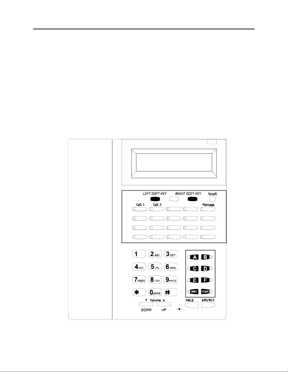
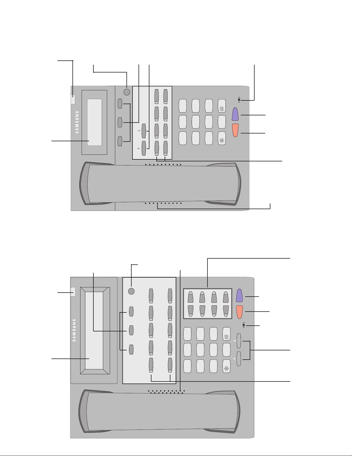
The diagram below illustrates the keys on a FALCON 28 BUTTON and a FALCON 18
BUTTON keyset that have special functions during programming. When required,
these keys will be referred to by the names described below.
1.1
Page 4
DCS 50si USER INSTRUCTIONS
TECHNICAL MANUAL PART 1 JUNE 2001
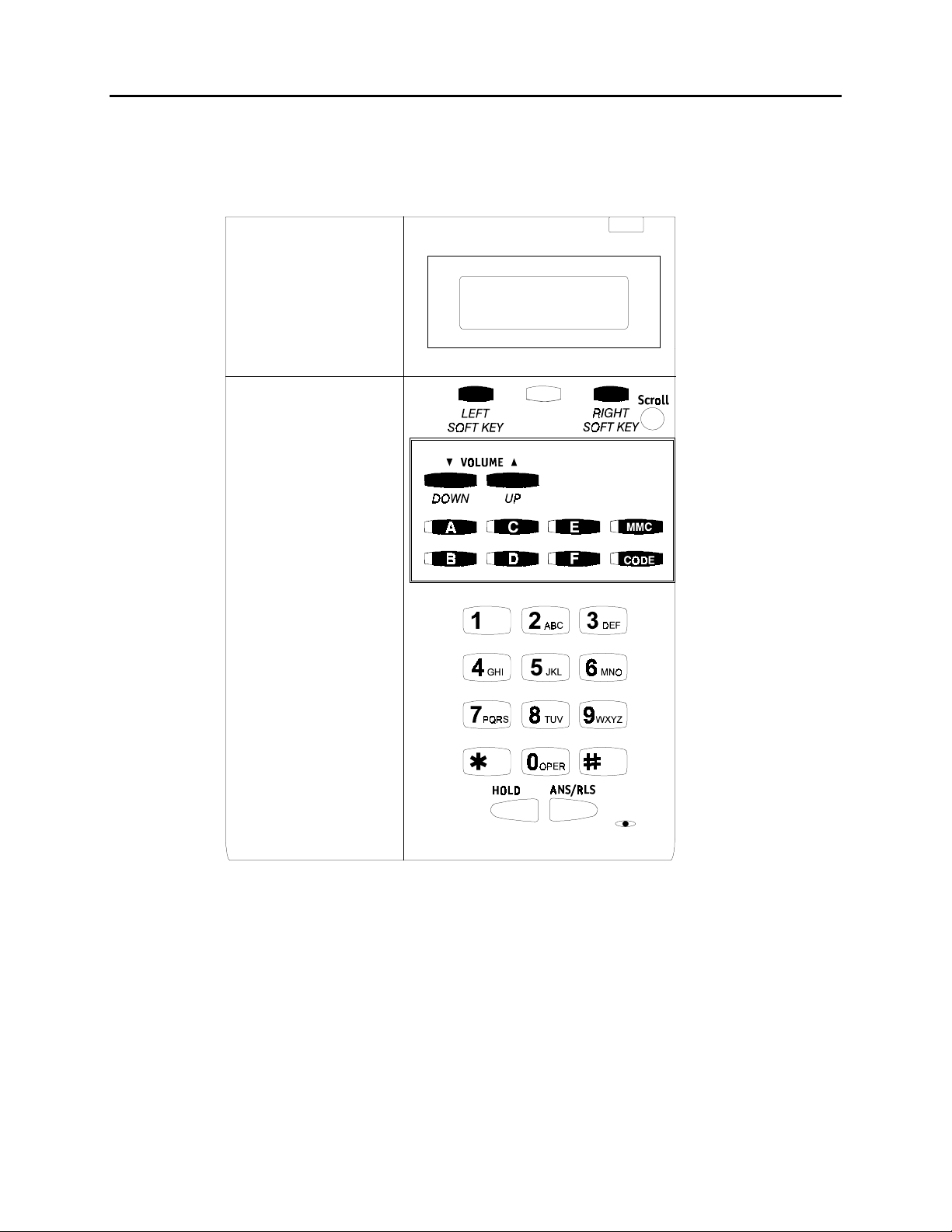
The diagram below illustrates the keys on a FALCON 8 BUTTON keyset that have
special functions during programming. When required, these keys will be referred to by
the names described below.
1.2
Page 5
DCS 50si USER INSTRUCTIONS
TECHNICAL MANUAL PART 1 JUNE 2001
DCS KEYSETS
•
This section provides more detailed programming procedures that can be used by
experienced display keyset users. These procedures will help explain some of the
displays observed as the simpler procedures detailed in the Keyset User Guide are
followed.
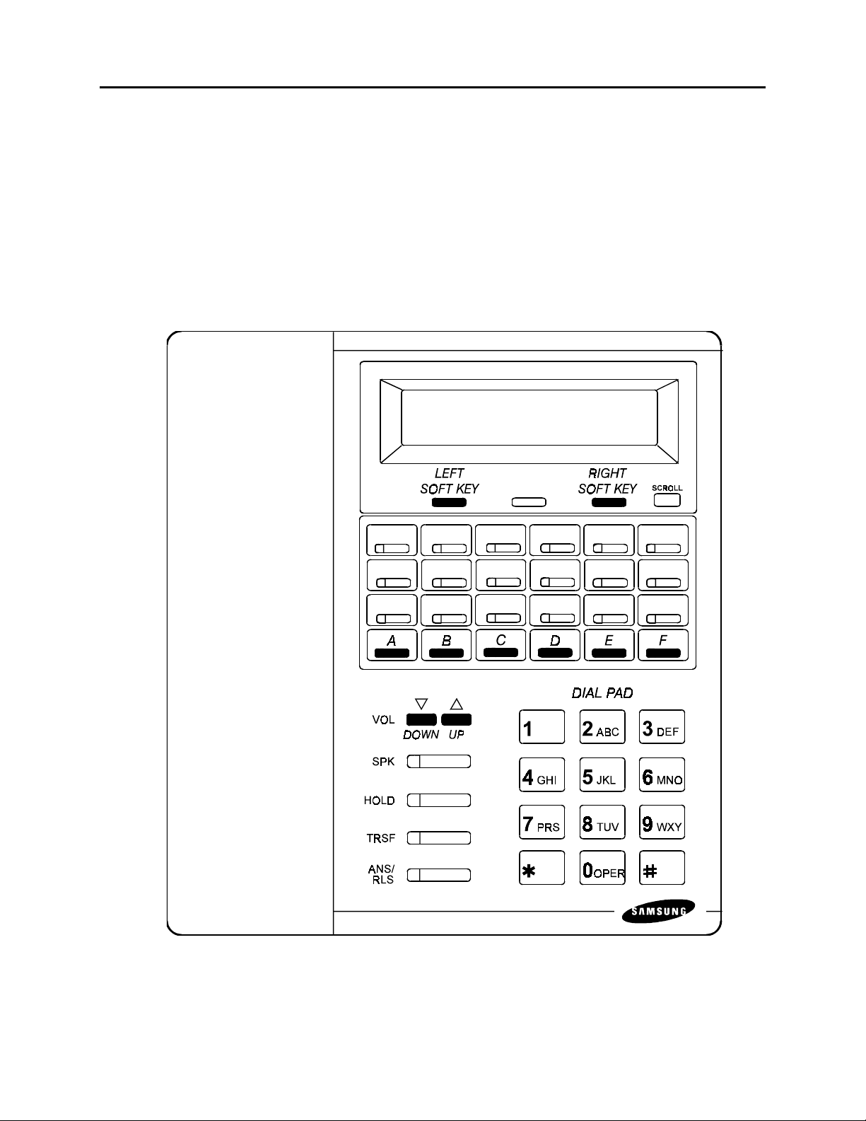
The diagram below illustrates the keys on a DCS display keyset that have special
functions during programming. When required, these keys will be referred to by the
names described below.
1.3
Page 6

DCS 50si USER INSTRUCTIONS
TECHNICAL MANUAL PART 1 JUNE 2001
1.2 LOCKING YOUR KEYSET
You can lock your keyset to prevent other people from making or receiving calls while
you are away. You can unlock it when you return.
ACTION DISPLAY
1. Press the transfer key followed by 100
Display shows
2. Enter your passocde
Default is 1234
3. Enter 1 for locking outgoing calls (Internal
calls will still be allowed).
4. Enter 2 for locking all calls (Internal and
external calls will not be allowed).
5. Enter 0 to unlock your phone.
6. Press the transfer key to save and exit
[201] STN LOCK
PASSCODE:_
[201] STN LOCK
UNLOCKED
[201] STN LOCK
LOCKED OUTGOING
OR
[201] STN LOCK
LOCKED ALL CALLS
[201] STN LOCK
UNLOCKED
1.4
Page 7

DCS 50si USER INSTRUCTIONS
TECHNICAL MANUAL PART 1 JUNE 2001
1.3 CHANGING YOUR PASSCODE
Each keyset user can set or change his/her individual passcode. This passcode is used
to lock or unlock keysets, for toll restriction override and to access the DISA feature.
NOTE: Default passcodes cannot be used for toll restriction override or for DISA
access.
ACTION DISPLAY
1. Press the transfer key followed by 101
Display shows
2. Enter the existing passcode (default = 1234)
3. Enter the new passcode
4. Reenter the new passcode to verify the number
If reentered correctly, display shows
5. Press the transfer key to save and exit
[201] PASSCODE
OLD CODE:_
[201] PASSCODE
OLD CODE:****
[201] PASSCODE
NEW CODE:_
[201] PASSCODE
VERIFY :SUCCESS
1.5
Page 8

DCS 50si USER INSTRUCTIONS
TECHNICAL MANUAL PART 1 JUNE 2001
1.4 CALL FORWARDING
The DCS 50si allows six types of call forwarding—Forward All, Forward No Answer,
Forward Busy, Forward Follow Me, Forward DND and Forward External. There is an
additional option, Forward Busy/No Answer, that allows both of these options to be
activated at the same time, provided destinations have been entered for both.
ACTION DISPLAY
1. Press the transfer key followed by 102
Display shows
2. Dial 0–6 to select the forward type (e.g., 1)
OR
Press UP or DOWN to select the forward type
Press the right soft key to move the cursor
3. Dial the destination number (e.g., 202)
OR
Press UP or DOWN to select the destination
Press the right soft key to move the cursor
4. Dial 1 to set
OR
Press UP or DOWN to select YES or NO
5. Press the transfer key to store and exit
[201] FORWARD
0:FORWARD CANCEL
[201] FORWARD
1:ALL CALL:NONE
[201] FORWARD
1:ALL CALL:202
[201] FORWARD
CURENTLY SET:YES
1.6
Page 9

DCS 50si USER INSTRUCTIONS
TECHNICAL MANUAL PART 1 JUNE 2001
1.5 SETTING YOUR ANSWER MODE
Each keyset and add-on module (AOM) can have its answer mode for intercom calls
set to one of the following options:
RING—The station will ring in one of eight custom ring patterns. Calls are answered by
pressing the ANS/RLS key or lifting the handset.
AUTO—After giving a short attention tone, the station will automatically answer calls on
the speakerphone. When a C.O. line is transferred to a station in Auto Answer, the
screened portion of the call will be Auto Answer, but the keyset or AOM will ring when
the transfer is complete if the user has not pressed the ANS/RLS key or lifted the
handset.
VOICE—The station will not ring. After a short attention tone, callers can make an
annoucement. The called party must press the ANS/RLS key or lift the handset to
reply.
ACTION DISPLAY
1. Press the transfer key followed by 103
Display shows
2. Dial 0, 1 or 2 to change the ring mode, e.g., 2
OR
[201] ANS MODE
RING MODE
[201] ANS MODE
VOICE ANNOUNCE
Press UP or DOWN to select the ring mode
3. Press the transfer key to store and exit
1.7
Page 10

DCS 50si USER INSTRUCTIONS
TECHNICAL MANUAL PART 1 JUNE 2001
1.6 PROGRAMMING YOUR STATION’S NAME
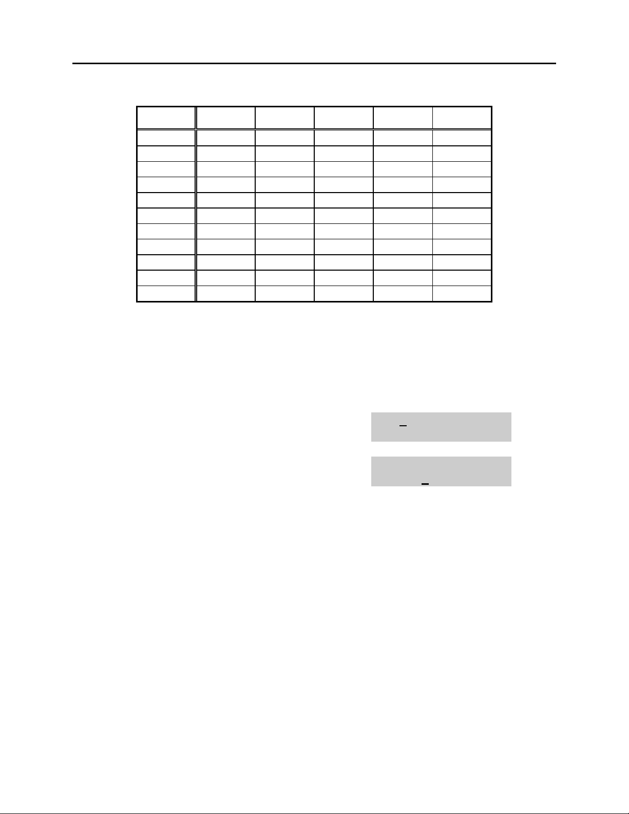
Names are written using the keypad. Each key press selects a character. Pressing the
dial pad key moves the cursor to the next position. For example, if the directory name is
“SAM SMITH,” press the number “7” three times to get the letter “S.” Press the number
“2” once to get the letter “A.” Continue selecting characters from the table below to
complete your message. Pressing the bottom left programmable key will change the
letter from upper case to lower case. There are up to 11 characters that can be used.
NOTE: When the character you want appears on the same dial pad key as the previous
character, press the VOL UP or DOWN keys to move the cursor to the right or to the
left.
DCS KEYSETS
•
COUNT12345
DIAL 0 Q Z . ) 0
DIAL 1 space ? , ! 1
DIAL 2 A B C @ 2
DIAL 3 D E F # 3
DIAL 4 G H I $ 4
DIAL 5JK L%5
DIAL 6 M N O ^ 6
DIAL 7 P R S & 7
DIAL 8 T U V
DIAL 9 W X Y ( 9
DIAL ✱ :=[ ]
✱
8
✱
The # key can be used for the following special characters: #, space, &, !, :, ?, ., %,
$, -, <, >, /, =, [, ], @, ^, (, ), _, +, {, }, |, ;, \, " and ~.
1.8
Page 11
DCS 50si USER INSTRUCTIONS
TECHNICAL MANUAL PART 1 JUNE 2001
FALCON KEYSETS
•
COUNT12345
DIAL 0 < > . ) 0
DIAL 1 space ? , ! 1
DIAL 2 A B C @ 2
DIAL 3 D E F # 3
DIAL 4 G H I $ 4
DIAL 5JK L%5
DIAL 6 M N O ^ 6
DIAL 7 P Q R S 7
DIAL 8 T U V
✱
8
DIAL 9 W X Y Z 9
DIAL ✱ :=[ ]
✱
1. When the character you want appears on the same dial pad key as the previous
character, press UP to move the cursor one space to the right.
2. Other symbols are available for DIAL #.
ACTION DISPLAY
1. Press the transfer key followed by 104
[201] STN NAME
Display shows
2. Enter the station name using the procedure
described above
[201] STN NAME
SAMSUNG
3. Press the transfer key to store and exit
1.9
Page 12

DCS 50si USER INSTRUCTIONS
TECHNICAL MANUAL PART 1 JUNE 2001
1.7 PROGRAMMING PERSONAL SPEED DIAL
LOCATIONS
You can program frequently dialed telephone numbers in a personal speed dial list.
Each station user begins with ten numbers 00–09 and may be assigned up to fifty
numbers. See your system administrator to determine the amount assigned to your
station.
NOTE: Press button B for flash and button C for pause.
Display keyset users may want to hide some speed dial numbers so they will not show
in the display. Before entering a telephone number, press button E. All digits after this
will be hidden. Press button E again to begin displaying digits.
If your system uses rotary (or pulse) dialing C.O. lines, pressing button D before
entering a speed dial will cause all subsequent digits to be sent as DTMF tones until
the D button is pressed again.
ACTION DISPLAY
1. Press the transfer key followed by 105
Display shows
If you have no speed dial bins,
the display will be as shown
2. Dial the location number (e.g., 05)
OR
Press UP or DOWN to select the location
Press the right soft key to move cursor
3. Enter the trunk access code (e.g., 9) followed
by the number to be dialed (e.g., 4264100)
OR
Press the left soft key to return to step 2
4. Press the F button to access the next program
OR
Press the transfer key to save and exit
[201] SPEED DIAL
00:
[201] SPEED DIAL
SPDBLK NOT EXIST
[201] SPEED DIAL
05:_
[201] SPEED DIAL
05:9-4264100_
1.10
Page 13

DCS 50si USER INSTRUCTIONS
TECHNICAL MANUAL PART 1 JUNE 2001
1.8 NAMING YOUR PERSONAL SPEED DIAL
LOCATIONS
This program allows a character name to be entered for each personal speed dial
location. This name enables the speed dial number to be located when using the
directory dial feature. The directory dial feature allows the display keyset user to select
a speed dial location by scanning its name. There are up to 11 characters that can be
used.
ACTION DISPLAY
1. Press the transfer key followed by 106
Display shows
2. Dial the speed dial location (e.g., 01)
OR
Use UP or DOWN to scroll through the location
numbers and use the right soft key to move the
cursor
3. Enter the location name using the procedure
described in Programming Your Station’s Name
4. Press UP or DOWN to move to the next
location
OR
Press the F key to program speed dial numbers
5. Press the transfer key to store and exit
[201] SPEED NAME
00:
[201] SPEED NAME
01:_
[201] SPEED NAME
01:SAMSUNG_
1.11
Page 14

DCS 50si USER INSTRUCTIONS
TECHNICAL MANUAL PART 1 JUNE 2001
1.9 ADDING EXTENDERS TO KEYS
This program allows you to assign key extenders to make a general access feature key
more specific. The feature keys that can have extenders are listed below:
FEATURE KEY DESCRIPTION EXTENDER
BOSS Boss and Secretary 1–4
DP Direct Pickup Extension or station group number
DS Direct Station Select Any extension number
FWRD Call Forward 0–6
GPIK Group Pickup 01–20
IG In/Out of Group Any group number you are part of
(501–509)
MMPG Meet Me Page 0–9, ✱
PAGE Page 0–9, ✱
SPD Speed Dial 00–49, 500–999
PSMG Programmed Message 01–20
DIR Directory PERS (1), SYS (2) or STN (3)
VT Voice Mail Transfer Voice Mail Group (501–529)
ACTION DISPLAY
1. Press the transfer key followed by 107
Display shows the first station
2. Enter the key number, e.g., 18
OR
[201] EXT (KTS)
01:CALL1
[201] EXT (KTS)
18:DS
Use UP and DOWN to scroll through the keys
Use the right soft key to move the cursor
OR
Press the key to be programmed
3. Dial the extender according to above table
Press the right soft key to return to step 2
[201] EXT (KTS)
18:DS DS207
OR
Press the transfer key to store and exit
OR
Press the speaker key to store and advance to
the next program
1.12
Page 15

DCS 50si USER INSTRUCTIONS
TECHNICAL MANUAL PART 1 JUNE 2001
1.10 CHECKING STATION STATUS
This program displays the following attributes of a station port. This is a read only
feature.
0 PORT # Port (1–80) / Slot (1–10) – Channel (1–16) / Offset (1–16)
1 TENANT NUMBER 1–2
2 PICKUP GROUP None, 01–30
3 SGR Station Group Number
4 BOSS-SECR None, 1–4
5 PAGE Page Zone (1–4)
6 DAY COS NO COS (01–30)
7 NIGHT COS NO COS (01–30)
ACTION DISPLAY
1. Press the transfer key followed by 108
Display shows
2. Press UP or DOWN to view the status items
3. Press the transfer key to exit
[201] STN STATUS
P01:S1-01 OFS:01
[201] STN STATUS
TYPE:24B US SET
1.13
Page 16

DCS 50si USER INSTRUCTIONS
TECHNICAL MANUAL PART 1 JUNE 2001
1.11 CHANGING YOUR TIME AND DATE DISPLAY
Display keysets will always have the date and time displayed when not in use. You can
select from the following display options:
0 COUNTRY Sets overall display format and has two options
0 = ORIENTAL MM/DD DAY HH:MM
1 = WESTERN DAY DD MM HH:MM
1 CLOCK Sets format of clock display and has two options
0 = 12 HOUR (Displays 1 P.M. as 01:00)
1 = 24 HOUR (Displays 1 P.M. as 13:00)
2 DISPLAY Sets format of DAY and MONTH display and has two options
0 = UPPER CASE (Displays Friday as FRI and March as MAR)
1 = LOWER CASE (Displays Friday as Fri and March as Mar)
ACTION DISPLAY
1. Press the transfer key followed by 109
Display shows
2. Press UP or DOWN to select the display mode
Press the right soft key to move the cursor
3. Press the right soft key to return to step 2
OR
Press the left soft key to return to step 3
4. Press the transfer key to store and exit
[201] DAY FORMAT
COUNTRY:WESTERN
[201] DAY FORMAT
COUNTRY:ORIENTAL
1.14
Page 17

DCS 50si USER INSTRUCTIONS
TECHNICAL MANUAL PART 1 JUNE 2001
1.12 SETTING STATION ON/OFF OPTIONS
The following options may be turned on and off at your keyset.
0. AME BGM This feature selects whether a station using Anwer Machine
Emulation will hear their personal greeting or BGM while
callers are listening to the personal greeting. A BGM source
must be selected for this to work. This feature applies only if
a CADENCE card is installed in the system.
1. AME PSWD If this option is set to YES, station users who have AME set
must enter their station password to listen to messages
being left.
2. AUTO HOLD Automatically places an existing C.O. call on hold if the
CALL button, trunk key or trunk route key is pressed during
that call. This will not affect the Auto Hold part of transfer
and park/page.
3. AUTO TIMER Automatically starts the stopwatch timer immediately when a
C.O. call is answered or after a short delay on an outgoing
call.
4. HEADSET USE When on, this feature disables the hook switch, allowing a
headset user to answer all calls on the headset without
requiring to lift the handset.
5. HOT KEYPAD When on, this feature allows the user to dial directory
numbers without having to first lift the handset or press the
speaker button.
6. KEY TONE Allows the user to hear a slight tone when pressing buttons
on the set.
7. PAGE REJOIN This feature allows keyset users to hear the remaining
portion of an ongoing internal page or all page over the
speaker of their keysets after they return their keysets to
idle. To enable this feature, follow the procedure below.
8. RING PREF. When off, this feature requires the user to press the fast
flashing button to answer a ringing call after lifting the
handset.
1.15
Page 18

DCS 50si USER INSTRUCTIONS
TECHNICAL MANUAL PART 1 JUNE 2001
ACTION DISPLAY
1. Press the transfer key followed by 110
Display shows
2. Dial the option number from above list (e.g., 4)
OR
Press UP or DOWN to select the option and
press the right soft key to move the cursor
3. Press UP or DOWN to select ON or OFF
Press the left or right soft key to return to step 2
OR
Dial 1 for ON or 0 for OFF
If option 0 from above list is dialed at
Step 2
If option 1 from above list is dialed at
Step 2
If option 2 from above list is dialed at
Step 2
[201] STN ON/OFF
AME BGM :OFF
[201] STN ON/OFF
HOT KEYPAD :OFF
[201] STN ON/OFF
HOT KEYPAD :ON
[201] STN ON/OFF
AME BGM :OFF
[201] STN ON/OFF
AME PSWD :OFF
[201] STN ON/OFF
AUTO HOLD :ON
If option 3 from above list is dialed at
Step 2
If option 4 from above list is dialed at
Step 2
If option 5 from above list is dialed at
Step 2
If option 6 from above list is dialed at
Step 2
If option 7 from above list is dialed at
Step 2
If option 8 from above list is dialed at
Step 2
4. Press UP or DOWN to select ON or OFF
Press the left or right soft key to return to step 2
[201] STN ON/OFF
AUTO TIMER :ON
[201] STN ON/OFF
HEADSET USE :OFF
[201] STN ON/OFF
HOT KEYPAD :ON
[201] STN ON/OFF
KEYTONE :ON
[201] STN ON/OFF
PAGE REJOIN :ON
[201] STN ON/OFF
RING PREF. :ON
[201] STN ON/OFF
HOT KEYPAD :ON
5. Press the transfer key to store and exit
1.16
Page 19

DCS 50si USER INSTRUCTIONS
TECHNICAL MANUAL PART 1 JUNE 2001
1.13 SELECTING A RING TONE
Each keyset user can select one of eight ring frequencies.
ACTION DISPLAY
1. Press the transfer key followed by 111
Display shows
2. Dial 1–8 to select the ring tone
OR
Press UP or DOWN to select the ring tone
Press the right soft key to move the cursor
3. Press the transfer key to store and exit
[201] RING TONE
SELECTION 6
[201] RING TONE
SELECTION 5
1.17
Page 20

DCS 50si USER INSTRUCTIONS
TECHNICAL MANUAL PART 1 JUNE 2001
1.14 ALARM REMINDER
Station users can have three alarms programmed at their phones. Each alarm may be
one of the following three types:
0. NOTSET The alarm is not set.
1. TODAY ONLY The alarm will ring at the programmed time and be canceled
automatically.
2. DAILY The alarm will ring each day at this time.
ACTION DISPLAY
1. Press the transfer key followed by 112
Display shows
2. Dial 1–3 to select the alarm (e.g., 2)
OR
Press UP or DOWN to select alarm
Press the right soft key to move the cursor
OR
Press the left soft key to return to step 2
3. Enter alarm time in 24 hour format (e.g., 1300)
Display automatically advances to step 5
4. Enter alarm type (e.g., 2)
OR
Press UP or DOWN to select alarm type
Press the right soft key to move the cursor
and return to step 2
5. Press the transfer key to store and exit
[201] ALM CLK(1)
HHMM: NOTSET
[201] ALM CLK(2)
HHMM: NOTSET
[201] ALM CLK (2)
HHMM:1300NOTSET
[201] ALM CLK
HHMM:1300DAILY
1.18
Page 21

DCS 50si USER INSTRUCTIONS
TECHNICAL MANUAL PART 1 JUNE 2001
1.15 SETTING A PROGRAMMED MESSAGE
When you will be away from your phone for any length of time, you can leave a vacant
station message. Display stations calling you will see this message and be informed of
your status or follow your instructions.
ACTION DISPLAY
1. Press the transfer key followed by 115
Display shows
2. Dial 00–20 to select message number, e.g., 05
OR
Press UP or DOWN to select message
3. Press the LEFT or RIGHT soft key to return to
step 2
OR
Press the transfer key to store and exit
[201] PGMMSG(00)
CANCEL VAC MSG
[201] PGMMSG(05)
PAGE ME
1.19
Page 22

DCS 50si USER INSTRUCTIONS
TECHNICAL MANUAL PART 1 JUNE 2001
1.16 ALARM REMINDER WITH MESSAGE
Station users can have three alarms programmed at their phones. Each alarm may be
one of the following three types:
0. NOTSET The alarm is not set.
1. TODAY ONLY The alarm will ring at the programmed time and be canceled
automatically.
2. DAILY The alarm will ring each day at this time.
In addition, each alarm may be accompanied by a 16 character message that will be
displayed while the alarm is ringing.
NOTE: These are the same three alarms described in Alarm Reminder. This procedure
allows a message to be added. A display keyset is necessary to view messages.
ACTION DISPLAY
1. Press the transfer key followed by 116
Display shows
2. Dial 1–3 to select the alarm (e.g., 2)
OR
Press UP or DOWN to select the alarm
Press the right soft key to move the cursor
3. Enter the alarm time in 24 hour clock format
(e.g., 1300)
Display automatically advances to step 4
4. Dial the valid entry from the above list for the
alarm type
OR
Press UP or DOWN to select the alarm type
Press the right soft key to move the cursor
5. Enter messages using the method in
Programming Your Station’s Name
Press the right soft key to return to step 2
[201] ALM REM(1)
HHMM: NOTSET
[201] ALM REM(1)
HHMM: NOTSET
[201] ALM REM (2)
HHMM:1300NOTSET
[201] ALM REM
HHMM:1300DAILY
[201] ALM REM
TAKE MEDICATION
6. Press the transfer key to store and exit
1.20
Page 23

DCS 50si USER INSTRUCTIONS
TECHNICAL MANUAL PART 1 JUNE 2001
1.17 CALLER ID DISPLAY
The station user can change the order in which the Caller ID information is displayed on
an LCD set.
Caller ID display options are the following:
0. NO DISPLAY No Caller ID data will be displayed.
1. NUMBER FIRST The Caller ID number received from the Central Office will be
displayed first.
2. NAME FIRST The Caller ID name received from the Central Office will be
displayed first.
ACTION DISPLAY
1. Press the transfer key followed by 119
Display shows current display mode
2. Dial display option 0, 1 or 2, e.g., 2
OR
Press UP or DOWN to select option
3. Press the transfer key to store and exit
OR
Press the speaker key to store and exit
[201] CID DISPLAY
NUMBER FIRST
[201] CID DISPLAY
NAME FIRST
1.21
Page 24

DCS 50si USER INSTRUCTIONS
TECHNICAL MANUAL PART 1 JUNE 2001
1.18 BACKGROUND MUSIC VOLUME
This procedure allows keyset users to view and adjust the level of background music
heard at their keysets.
ACTION DISPLAY
1. Press the transfer key followed by 117
Display shows
2. Enter volume level (01-16)
3. Press the transfer key to store and exit
[201] BGM VOLUME
VOLUME 13
[201] BGM VOLUME
VOLUME 06
1.22
Page 25

TABLE OF CONTENTS
ABOUT THIS BOOK ..........................................................1
THINGS YOU SHOULD KNOW ............................2–9
ASSEMBLING YOUR KEYSET ................................10
ADDING A KEYSET DAUGHTERBOARD
MODULE
..............................................................................11
OUTSIDE CALLS
Making an Outside Call ....................................................................12
Answering an Outside Call................................................................12
Universal Answer ..............................................................................12
Recall/Flash ......................................................................................13
Busy Line Queuing with Callback ....................................................13
Canceling Callback............................................................................13
INTERCOM CALLS
Calling Other Stations ......................................................................14
Answering Intercom Calls..................................................................14
Answer Modes ..................................................................................14
Busy Station Callback ......................................................................15
Busy Station Camp-on ......................................................................15
Calling Your System Operator ..........................................................15
CALL PROCESSING
Holding Calls................................................................................16–17
Transferring Calls ........................................................................17–18
Transfer with Camp-On......................................................................18
Transfer to Voice Mail ........................................................................18
Call Waiting........................................................................................18
Conference Calls ..............................................................................19
Forwarding Calls..........................................................................19–22
Call Pickup ........................................................................................22
SAMSUNG DCS 50si SYSTEM
June 2001
FALCON
KEYSET USER GUIDE
Every effort has been made to eliminate errors and ambiguities in the information contained in this
guide. Any questions concerning information presented here should be directed to SAMSUNG TELE-
COMMUNICATIONS AMERICA, 2700 N.W. 87th Avenue, Miami, FL 33172, telephone (305) 592-2900.
SAMSUNG TELECOMMUNICATIONS AMERICA disclaims all liabilities for damages arising from the
erroneous interpretation or use of information presented in this guide.
Page 26

CUSTOMIZING YOUR KEYSET
AME BGM ..........................................................................................34
AME Password ..................................................................................34
Answer Machine Emulation ..............................................................34
Select Ring Tone................................................................................35
Change Your Passcode ....................................................................35
Set Answer Mode ..............................................................................35
Automatic Hold ..................................................................................36
Headset Operation ............................................................................36
Hot Keypad........................................................................................36
Key Confirmation Tone ......................................................................37
Rejoining a Page ..............................................................................37
Ring Preference ................................................................................37
DISPLAY FEATURES
Interactive Display Keys ....................................................................38
Directory Information ...................................................................... 38
Dial by Directory ................................................................................39
Call Progress Displays ......................................................................39
Display Number Dialed......................................................................39
Call Duration Timer............................................................................39
Auto Timer ........................................................................................40
Timer Function ..................................................................................40
Viewing Message Indications............................................................40
Alarm Reminder Messages ........................................................40–41
Personal Speed Dial Names ............................................................41
Station Names ..................................................................................42
Managing Key Assignments..............................................................42
Caller ID ......................................................................................43–46
LCR with Clear ..................................................................................46
64 BUTTON MODULE WITH KEYSET ..............47
DIALING FEATURES
Speed Dialing ....................................................................................23
Programming Personal Speed Dial Numbers ............................23–24
One Touch Speed Dialing ................................................................24
Last Number Redial ..........................................................................24
Save Number with Redial..................................................................24
Chain Dialing ....................................................................................25
Automatic Redial/Retry ......................................................................25
Pulse to Tone Changeover ................................................................25
PAGING AND MESSAGING
Making an Internal Page....................................................................26
Making an External Page ..................................................................26
All Page..............................................................................................26
Meet Me Page....................................................................................27
Call Park and Page............................................................................27
Messages—Set and Cancel ........................................................27–28
Returning Messages..........................................................................28
Programmed Messages ....................................................................28
CONVENIENCE FEATURES
Do Not Disturb ..................................................................................29
One Time DND ..................................................................................29
Mute ..................................................................................................29
Background Music ............................................................................29
Appointment Reminder/Alarm Clock ................................................30
Door Phone Calls ........................................................................30–31
Executive/Secretary Hotline ..............................................................31
Group Listening ................................................................................31
Account Codes ..................................................................................31
Locking Your Keyset..........................................................................32
Off-Hook Voice Announce ..........................................................32–33
OHVA Block ......................................................................................33
OHVA Reject ......................................................................................33
In Group/Out of Group ......................................................................33
Page 27

ABOUT THIS BOOK
Your FALCON keyset is the most visible part of your telephone system. No
matter what model keyset you are using telephone calls are handled the
same way. The 28B and 18B keysets have additional conveniences that are
not available to 8B keyset users. These are noted throughout this guide.
Please take the time to study this guide and to become familiar with the op-
eration of your keyset. Keep this guide handy. You may need to look up in-
structions for infrequently used features.
Learning to use your keyset correctly will make everyday telephone commu-
nications a breeze.
1
SVMi-4 .........................................................................................48
Flow Chart .........................................................................................49
Accessing your Mailbox ....................................................................49
Getting Started ..................................................................................50
Listening to your Messages ..............................................................50
Message Forwarding Options...........................................................51
Sending Messages............................................................................51
Personal Greetings............................................................................52
Mailbox Administration......................................................................52
Personal Services..............................................................................53
Keyset User Features ........................................................................53
Interactive Displays for SVMi-4 .........................................................54
PERSONAL SPEED DIAL NUMBERS...........55-56
Page 28

3
Your outside calls will light green on your keyset and red on other keysets.
You never lose sight of your calls while they are on hold. They stay right
where you put them and are identified with a green flashing light.
Some simple rules to remember:
• Any steady LED indicates the line or feature is in use.
• A fast flashing green LED indicates a new call ringing in.
• A slow flashing green or red LED indicates a call is on hold.
• A slow flashing amber LED indicates a recall to your keyset.
SPEAKERPHONE
All FALCON keysets are speaker phones. Pressing ANS/RLS key will answer
or release a call on the speakerphone. Switching from the handset to the
speakerphone is easy. Press the SPEAKER key and hang up the handset.
VOLUME CONTROLS
The FALCON keysets use the UP and DOWN keys to adjust the ringer vol-
ume while the keyset is ringing, the speaker volume while the speakerphone
is in use and the handset volume while you are listening. These three levels
will be stored in memory until changed. If background music is turned on at
your keyset, the volume keys will also control the level of music. The volume
of pages heard through the speaker of a keyset can be adjusted during a
page announcement by using the volume keys. There are 16 levels for each
volume setting. The volume of off-hook ring is controlled by a user-program-
mable setting.
TERMINAL STATUS INDICATOR
The terminal status indicator light is positioned on the top right corner of the
keyset above the display. The terminal status indicator is a tri-colored (red,
green, and amber) light that provides greater visibility of your keysets status
than the individual key LEDs. The terminal status indicator provides the fol-
lowing indications:
• Busy/Off Hook Steady Red
• Intercom Ring Flashing Red
• Outside Call Ring Flashing Green
• Recall Ring Flashing Amber
• Message Waiting Flashing Red
• Do Not Disturb Fast Flash Red at 1 Second Intervals
THINGS YOU SHOULD KNOW
USER ORIENTATION
FALCON telephones are called “keysets.” They contain buttons or “keys”
that are used to access or activate the many features of your office phone
system. The keys with paper designation strips are programmable keys. This
means they can be programmed for a specific function on your keyset and
that same button can be something different on another keyset. See the sys-
tem manager to get your most frequently used features assigned to your
programmable keys. When changes are made, be sure that your program-
mable keys are relabeled properly.
Lines from the telephone company are “C.O. lines.” Calls on these lines are
referred to as “outside calls.” Your system can have individual C.O. line keys
or lines may be assigned to groups. When they are in a group, you access
a line by dialing an access code or pressing a route button. For example, dial
9 or press a “LOCAL” key to get a local outside line. If Least Cost Routing is
used, pressing the “LCR” key will automatically select a preprogrammed
C.O. line according to what digits are dialed. Each line in the system is num-
bered, beginning with 701, then 702, 703, etc.
Direct Station Selection (DSS) keys are programmed to ring specific sta-
tions. You can press a DSS key instead of dialing the extension number. A
DSS key lights red when that station is busy (Busy Lamp Indication).
Falcon keysets provide distinctive ring patterns:
• Outside calls have a single ring tone repeated.
• Internal calls have a double ring tone repeated.
• Door phone calls and alarm/appointment reminders have a triple ring
tone repeated.
CALL INDICATIONS
The keys on your phone have light emitting diodes (LEDs). These are tri-col-
ored LEDs that light green, red or amber (green and red together).
Intercom calls, also called internal calls, always appear on your CALL but-
tons. They will always light green. You can have up to eight CALL buttons,
but at least two are recommended.
Outside calls appear on individual line keys if they are assigned. When an
individual line is not assigned to its own key, it will appear on a CALL button.
2
Page 29

5
28 BUTTON FALCON KEYSET
Scroll
Call 1 Call 2 Message
Memory Redial
Transfer Speaker
HOLD
ANS/RLS
Volume
1
2
ABC
3 DEF
4 GHI
5 JKL
6 MNO
7PQRS
8 TUV
9WXYZ
0OPER
FALCON 28B
32 CHARACTER DISPLAY
Two lines with 16 characters each.
TERMINAL STATUS INDICATOR
Used to provide your keyset status.
SOFT KEYS
Used to acti-
vate features
via the display.
SCROLL KEY
Used to scroll
through dis-
plays.
20 PROGRAMMABLE KEYS
WITH TRI-COLORED LIGHTS
Used for CALL buttons, intercom
calls, outside lines and many other
system features.
8 PROGRAMMABLE KEYS WITH
TRI-COLORED LIGHTS Used to
call stations directly, to indicate
busy conditions of other stations,
for One Touch dialing and many
other system features.
VOLUME CONTROL
KEYS Used to set inde-
pendent levels for handset,
speaker, background
music, ring and page vol-
umes.
MICRO-
PHONE
For handsfree
operation.
ANSWER/RELEASE KEY
HOLD KEY
SPEAKER
For hands-
free opera-
tion and ring-
ing.
4
FEATURE ACCESS CODES
This user guide is written based on the default access code for using sys-
tem features. If the system numbering plan has been changed some of the
access codes may not be correct. Your installing company can inform you
of the correct codes.
SYSTEM TONES
The system provides several tones to assist you. Some of these tones are
already familiar to you.
CONTINUOUS
Intercom Dial Tone—A steady tone that indicates you can begin dialing.
DIAL TONE
RINGBACK TONE—1000 ms ON/3000 ms OFF
Ringback Tone—Indicates the station you dialed is ringing.
CONTINUOUS
BUSY TONE—500 ms ON/500 ms OFF
Busy Tone—Indicates the station you dialed is busy.
CONTINUOUS
DND/No More Calls Tone—Fast busy tone indicates the station you
dialed is in the Do Not Disturb mode or cannot receive any more calls.
DND/NO MORE CALLS TONE—250 ms ON/250 ms OFF
FOR TEN SECONDS
Transfer/Conference Tone—Indicates your call is being held and you
CONTINUOUS
TRANSFER/CONF TONE—100 ms ON/100 ms OFF
can dial another party.
Confirmation Tone—Very short beeps followed by dial tone indicate you
CONFIRMATION TONE—50 ms ON/50 ms OFF
have correctly set or canceled a system feature.
FOR ONE SECOND
(programmable)
Error Tone—A distinctive two level beeping tone indicates you have
ERROR TONE—50 ms of tone 1/50 ms of tone 2
done something incorrectly. Try again.
FOR THREE SECONDS
Page 30
7
8 BUTTON FALCON KEYSET
Scroll
HOLD
ANS/RLS
1
2
ABC
3 DEF
4 GHI
5 JKL
6 MNO
7PQRS
8 TUV
9WXYZ
0OPER
Call 1 Call 2
Message Transfer
Speaker
VOLUME
FALCON 8B
32 CHARACTER DISPLAY
Two lines with 16 characters each.
TERMINAL STATUS INDICATOR
Used to provide your keyset status.
SOFT KEYS Used to
activate features via the
display.
SCROLL KEY Used to
scroll through displays.
8 PROGRAMMABLE KEYS WITH
TRI-COLORED LIGHTS Used to
call stations directly, to indicate
busy conditions of other stations,
for One Touch dialing and many
other system features.
VOLUME CONTROL
KEYS Used to set inde-
pendent levels for hand-
set, speaker, background
music, ring and page vol-
umes.
MICROPHONE
For handsfree opera-
tion.
ANSWER/
RELEASE KEY
HOLD KEY
SPEAKER
For hands-
free opera-
tion and ring-
ing.
6
18 BUTTON FALCON KEYSET
Scroll
Call 1 Call 2 Message
Memory Redial
Transfer Speaker
HOLD
ANS/RLS
Volume
1
2
ABC
3 DEF
4 GHI
5 JKL
6 MNO
7PQRS
8 TUV
9WXYZ
0OPER
FALCON 18B
32 CHARACTER DISPLAY
Two lines with 16 characters each.
TERMINAL STATUS INDICATOR
Used to provide your keyset status.
SOFT KEYS
Used to acti-
vate features
via the display.
SCROLL KEY
Used to scroll
through dis-
plays.
10 PROGRAMMABLE KEYS
WITH TRI-COLORED LIGHTS
Used for CALL buttons, intercom
calls, outside lines and many other
system features.
8 PROGRAMMABLE KEYS WITH
TRI-COLORED LIGHTS Used to
call stations directly, to indicate
busy conditions of other stations,
for One Touch dialing and many
other system features.
VOLUME CONTROL
KEYS Used to set inde-
pendent levels for handset,
speaker, background
music, ring and page vol-
umes.
MICRO-
PHONE
For handsfree
operation.
ANSWER/RELEASE KEY
HOLD KEY
SPEAKER
For hands-
free opera-
tion and ring-
ing.
Page 31

KEYSET DAUGHTER MODULES
[28 AND 18 BUTTON KEYSETS ONLY]
Falcon 28 and 18 button keysets can have one of three different types of
daugher module installed on them to enhance the operation of the keyset or
to provide an additional local port depending on the type of module.
FALCON KDB-DIGITAL LINE
INTERFACE (FKDBD)
If your keyset is connected to a Digital Line Interface (DLI) port that supports
2B+D operation (your installing company can determine this) you may
install a daughter module that provides a Digital Line Interface (DLI) port for
connection of a digital station device such as a keyset or 64 button module.
FALCON KDB-SINGLE LINE
INTERFACE (FKDBS)
If your keyset is connected to a Digital Line Interface (DLI) port that supports
2B+D operation (your installing company can determine this) you may
install a daughter module that provides a Single Line Interface (SLI) port for
connection of a standard telephone device such as a cordless phone.
FALCON KDB-FULL DUPLEX (FKDBF)
The standard speakerphone mode of operation for a Falcon keyset is “half
duplex”. This means that you cannot transmit and receive speech at the
same time. Adding a FKDBF to your keyset will convert the speakerphone
into full duplex mode enhancing its operation. In addition the FKDBF may
have up to three (3) external microphones attached to it for conference room
type applications. These microphones require an “EXTMIC” key pro-
grammed on the keyset to activate or deactivate them.
98
64 BUTTON FALCON AOM
12345
678910
11 12 13 14 15
16 17 18 19 20
21 22 23 24 25
26 27 28 29 30
31 32 33 34 35
36 37 38 39 40
41 42 43 44 45
46 47 48 49 50
51 52 53 54 55
56 57 58 59 60
61 62 63 64
64 PROGRAMMABLE KEYS
WITH RED LIGHTS Used to call
stations directly, to indicate busy
conditions of other stations, for
One Touch dialing and many other
system features.
Page 32

11
ADDING A KEYSET
DAUGHTERBOARD MODULE
• Place the keyset face down on a flat surface.
• Remove the base pedestal by placing your thumbs over the attachment
clips and press outward while simultaneously pressing down on the key-
set body with your fingertips.
• Remove the two knockouts from the bottom of the keyset.
• Plug in the daughter module and secure with the two screws provided.
10
ASSEMBLING YOUR KEYSET
• Place the keyset face down on a flat surface.
• Remove the base pedestal by placing your thumbs over the attachment
clips and press outward while simultaneously pressing down on the key-
set body with your fingertips.
• Plug the handset cord into the jack marked with the symbol.
• Route the handset cord out the RIGHT side of the keyset as you look at
it face down.
• Reattach the base pedestal.
• Plug the line cord into the jack on the base of the keyset marked with the
symbol and route it through one of the cable channels in the bottom
of the base pedestal.
SECURING
SCREWS
REMOVE
KNOCKOUTS
Page 33

RECALL DIAL TONE
Press the NEW button to disconnect your existing call, wait for dial tone and
then make a new call on the same line.
NOTE: If this button does not appear on your keyset, the FLASH key may
be programmed to recall dial tone.
SENDING A FLASH
While on an outside call, press the FLASH key to send a flash to the tele-
phone company. This is required for some custom calling features or CEN-
TREX use.
BUSY LINE QUEUING WITH CALLBACK
If you receive a busy signal when you are selecting an outside line, this
means that the line or group of lines is busy.
• Press the CBK key or dial 44. You will hear confirmation tone.
• When the line becomes free, the system will call you back.
• Lift the handset or press the ANS/RLS key to answer, wait for dial tone
and dial the telephone number or speed dial number again.
NOTES:
1. A callback will be canceled if not answered within 30 seconds. If you
have set a callback, your CBK key will light.
2. If the Hot Keypad feature has been turned off, you must first lift the hand-
set or press the SPEAKER key before dialing.
CANCELING CALLBACK
A callback will be canceled if not answered within 30 seconds. If you have
set a callback, your CBK key will light.
Your phone may have a maximum of five callbacks on stations and/or lines
set at a time. To cancel a callback:
• Press the CBK key or dial 44. You will hear confirmation tone.
• While you are listening to confirmation tone, press the HOLD key. This
will cancel the oldest callback that you have set.
NOTES:
1. If the hot keypad feature is turned off, you must first lift the handset or
press the SPEAKER key before dialing.
1312
OUTSIDE CALLS
MAKING AN OUTSIDE CALL
• Lift the handset and press an idle outside line button, line group button
or dial a line access code to receive dial tone—OR—press an idle out-
side line button, line group button or dial a line access code to receive
dial tone through the speaker—OR—press SPEAKER receive intercom
dial tone and dial a line access code.
• Dial the telephone number.
• Finish the call by replacing the handset or pressing the ANS/RLS key.
NOTE: You will receive No More Calls tone when you attempt to make a call
and there is no key available for that line.
• If Least Cost Routing is enabled on your phone system, this button may
be labeled LCR or accessed by dialing an access code (usually 9).
• If your system is programmed to require an authorization code before
making a call, dial ✱ plus a valid code before selecting a C.O. line.
• If your system is programmed to require an account code before mak-
ing a call, press the ACCT button or dial 47 plus a valid code, press the
ACCT button again and then select a C.O. line.
For more information on authorization and account codes, see your system
administrator.
NOTE: If the Hot Keypad feature has been turned off, you must first lift the
handset or press the SPEAKER key before dialing.
ANSWERING AN OUTSIDE CALL
• Lift the handset and you are automatically connected to the ringing call.
See Ring Preference under Customizing Your Keyset—OR—press the
ANS/RLS key to automatically answer on the speakerphone.
NOTE: If a call is flashing at your keyset but not ringing, you must press the
flashing button to answer.
UNIVERSAL ANSWER
Outside lines may be programmed to ring a general alerting device. To an-
swer calls ringing this device, dial 67 or press the UA key. This device can
operate in the Day or Night mode.
NOTE: If the Hot Keypad feature has been turned off, you must first lift the
handset or press the SPEAKER key before dialing.
Page 34

BUSY STATION CALLBACK
When you call another station and receive a busy signal:
• Press the CBK key or dial 44.
• When the busy station becomes free, your keyset will ring.
• Lift the handset or press ANS/RLS to call the now idle station.
NOTES:
1. A callback will be canceled if not answered within 30 seconds. If you
have set a callback, your CBK key will light.
2. If the Hot Keypad feature has been turned off, you must first lift the hand-
set or press the SPEAKER key before dialing.
BUSY STATION CAMP-ON
When you call another station and receive a busy signal but you do not want
to wait for a callback:
• Press the CAMP key or dial 45.
• The called station will receive off-hook ring tone repeated every few sec-
onds and its first available CALL button will flash green to indicate your
call is waiting.
• Wait for the called party to answer.
• The called station must release its first call or place it on hold before an-
swering your camp-on.
NOTES:
1. If you receive No More Calls tone, that station has no available key to ac-
cept your call. Hang up or leave a message.
2. If the Hot Keypad feature has been turned off, you must first lift the hand-
set or press the SPEAKER key before you begin dialing.
CALLING YOUR SYSTEM OPERATOR
• Dial 0 to call your system operator or group of operators.
• If you want to call a specific operator, dial that person’s extension num-
ber.
NOTE: If the Hot Keypad feature has been turned off, you must first lift the
handset or press the SPEAKER key before you begin dialing.
1514
INTERCOM CALLS
CALLING OTHER STATIONS
• Dial the extension number or group number.
• Wait for the party to answer. If you hear a brief tone burst instead of ring-
back tone, the station you called is set for Voice Announce or Auto
Answer. Begin speaking immediately after the tone.
• Finish the call by replacing the handset or pressing the ANS/RLS key.
NOTES:
1. If you have a DSS key assigned to an extension or station group, you
may press this key instead of dialing the number.
2. If the Hot Keypad feature has been turned off, you must first lift the hand-
set or press the SPEAKER key before you begin dialing.
ANSWERING INTERCOM CALLS
• When your keyset rings, simply lift the handset—OR—press the
ANS/RLS key to be connected to the calling station.
• Finish the call by replacing the handset or pressing the ANS/RLS key.
See Ring Preference under Customizing Your Keyset.
VOICE ANNOUNCE MODE
(INTERCOM CALLS ONLY)
When another station calls you, your keyset will sound a brief attention tone
and you will hear the caller’s announcement.
• Press ANS/RLS to turn on the microphone and speak handsfree—OR—
lift the handset to reply.
• To finish the call, replace the handset or press the ANS/RLS key.
AUTO ANSWER MODE
(INTERCOM CALLS ONLY)
When another station calls you, your keyset will sound a brief attention tone
and then automatically answer the call.
• Your microphone and speaker are turned on and you can speak hands-
free. For privacy, use the handset.
• To finish the call, replace the handset or press the ANS/RLS key.
Page 35

• If you do not answer this recall within a pre-programmed period of time,
it will go to the system operator.
CONSULTATION HOLD
When you are talking on an outside line and it is necessary to consult with
another extension:
• Press the TRANSFER key; you will receive transfer dial tone. Your call is
placed on transfer hold.
• Dial the extension number.
• Consult with the internal party.
• Press TRANSFER to return to the outside party or hang up to transfer
the call.
NOTE: Repeatedly pressing the TRANSFER key will toggle between the
outside party and internal extension.
RETRIEVING CALLS HELD AT
ANOTHER STATION
When a line is on hold and it appears on your keyset, press the line button
with the red flashing light.
When a line is on hold and it does not appear on your keyset, dial 12 plus
the line number or the extension number of the station that placed the call
on hold.
NOTE: If the Hot Keypad feature has been turned off, you must first lift the
handset or press the SPEAKER key before you begin dialing.
TRANSFERRING CALLS
Transfer is used to send any call to another extension in one of two ways.
You can do a screened transfer by informing the other extension who is call-
ing or you can do a blind transfer without notification.
• While on a call, press the TRANSFER key and dial an extension number
or group number. Your call is automatically put on transfer hold.
OR
Press a DSS key or station group key. Your call is automatically put on
transfer hold.
• Hang up when you hear ringing (this is an unscreened or blind transfer).
OR
Wait for the called party to answer and advise him/her of the call and
hang up. If the transfer is refused, you will be reconnected to the outside
1716
CALL PROCESSING
SYSTEM HOLD
• When you are connected to any call, press HOLD. The call will flash
green at your keyset. If this call appears on a line key at other keysets,
it will flash red at those keysets.
• To take the caller off hold, press that key and the green flashing light will
go steady green again. Resume the conversation.
NOTE: While on a call, pressing a line key, route key or flashing CALL but-
ton will automatically put your first call on hold and connect you to the new
call. See Automatic Hold under Customizing Your Keyset.
EXCLUSIVE HOLD
To place an outside call on hold at your phone so that other users cannot get it:
• Press the HOLD button twice. The call will flash green on your keyset
and this line will show a steady red light on other keysets.
• To retrieve the call, press the flashing green line button or press the
HOLD button a third time.
NOTE: Intercom calls will always be placed on exclusive hold.
REMOTE HOLD
When you wish to place a call on hold at another station. Press TRANSFER
and dial the station number (or press the appropriate DSS key). Press the
HOLD key. This will place the call on system hold on an available CALL but-
ton or Line Key at the remote station and return you to dial tone.
NOTES:
1. If the destination station does not have any free CALL buttons or line
keys you will hear No More Calls tone and must return to the other party
by pressing the TRANSFER key (or the RETURN soft key in the display).
2. Intercom calls cannot be remote held.
HOLD RECALL
If you leave a call on hold longer than the hold timer, it will recall your sta-
tion. The button that the call appears on will have a slow flashing amber light.
• When your phone rings, lift the handset or press the ANS/RLS key to an-
swer the recall.
Page 36

Finish the first call and hang up; the waiting call will ring.
• Lift the handset or press the ANS/RLS key to answer.
NOTE: Intercom calls will not go on Automatic Hold.
CONFERENCE CALLS
You may conference up to five parties (you and four others) in any combina-
tion of outside lines and internal stations in any order.
• While engaged in a conversation, press the CONF key and receive con-
ference tone.
• Make another call, either intercom or outside, press the CONF key and
receive conference tone.
• Make another call or press the CONF key to join all parties.
• Repeat the last step until all parties are added.
NOTE: When attempting to add another party to the conference and you are
not able to reach the desired person, hang up. Simply press the CONF key
again to return to your previous conversation.
To drop a party from your conference call:
• Press CONF and dial the extension or line number that is to be dropped.
• Press CONF again to reestablish the conference.
NOTE: To leave the conference, hang up. Control is passed to the next inter-
nal station. If there are no internal stations and you wish to leave outside
lines connected together in a trunk to trunk conference, press the CONF key
plus the CALL button that the call appears on or follow the instructions to
drop a party and use your extension number. When they hang up, the lines
will release automatically. Press CONF to rejoin a trunk to trunk conference.
FORWARDING CALLS
You may forward your calls to another station, group of stations or an exter-
nal telephone number. Program a destination for the type of forwarding you
want as detailed below. If you have FWD ALL, FWD BUSY and FWD NO
ANSWER keys, press one to turn that forward feature on. A steady red light
reminds you what forward condition is activated.
You can clear all call forward conditions set at your station by lifting the hand-
set and dialing 600.
19
line when the called station hangs up or you can press TRANSFER to
return to the outside party. If you wish to send the call to another exten-
sion without waiting for the first station to hang up, simply press anoth-
er DSS button. OR
Press the CALL button or C.O. line key to return to the outside party and
begin the transfer process again.
When you are transferring a call to a keyset set for Voice Announce or Auto
Answer, the transferred call will always ring.
NOTES:
1. After the inside party answers, you may alternate back and forth
between the parties by pressing the TRANSFER key.
2. If you receive No More Calls tone, that station has no key available to re-
ceive another call. Press TRANSFER to return to the other party.
3. You cannot transfer an Intercom call by pressing a DSS key. You must
press the TRANSFER key and dial the destination extension number.
TRANSFER WITH CAMP-ON
When you are transferring a call to another station and you receive a busy
signal, you may camp the call on to this station. Simply hang up when you
hear the busy signal. The called party will be alerted that a call is waiting for
them.
NOTE: If you receive No More Calls tone, that station has no key available
to receive another call. Press TRANSFER to return to the outside caller.
TRANSFER TO VOICE MAIL
This feature is used to send a call directly to a voice mailbox. Your keyset
must have a correctly programmed VT key to accomplish this. To transfer a
call directly to a voice mailbox:
• While on a call, press the VT key and dial the mailbox number.
• Hang up when dialing is completed.
CALL WAITING
If an outside call has been camped-on to your phone or another station has
camped-on to you:
• Your keyset will ring and the call that is waiting for you (camped-on) will
flash green.
• Press the flashing button to answer; your other call will go on hold auto-
matically if your station has the Automatic Hold feature set. If not, you
must press HOLD and then the flashing button. OR
18
Page 37

FORWARD FOLLOW ME
When you want all calls to your extension forwarded to the extension where
you are now:
• Dial 605 plus your extension number.
• Receive confirmation tone and hang up.
If you want a specific extension’s calls forwarded to your phone (Remote Call
Forward):
• Dial 605 plus the desired extension number.
• Receive confirmation tone and hang up.
NOTE: If the Hot Keypad feature has been turned off, you must first lift the
handset or press the SPEAKER key before you begin dialing.
FORWARD TO AN EXTERNAL NUMBER
To forward outside calls to a number outside of your business, you must
have a FWD EXTERNAL button on your keyset.
• While on-hook, press TRANSFER and then dial 102.
• Dial 6.
• Dial the trunk or trunk group access code followed by the telephone
number that you want.
• Press TRANSFER to store.
• Press FWD EXTERNAL to turn the feature on and press it again to turn
the feature off.
NOTES:
1. External Call Forward will cancel all other call forwarding instructions.
2. If the Hot Keypad feature has been turned off, you must first lift the hand-
set or press the SPEAKER key before you begin dialing.
FORWARD DND
To forward your phone when you activate DND.
• Dial 607 plus the extension number or group number.
• Receive confirmation tone and hang up.
NOTE:
1. If the Hot Keypad feature has been turned off you must first lift the hand-
set or press the SPEAKER key before you begin dialing.
2120
FORWARD ALL CALLS
To forward all your calls under any condition to another station:
• Dial 601 plus the extension or group number.
• Receive confirmation tone and hang up.
NOTES:
1. If the Hot Keypad feature has been turned off, you must first lift the hand-
set or press the SPEAKER key before you begin dialing.
2. The station that receives a Forwarded All call can transfer the call to the
forwarded station. This is useful when you are expecting an important
call but you do not wish to be disturbed by other calls.
3. When a station user places his/her keyset in Forward All mode and
he/she does not have a FORWARD ALL key, the TRANSFER key will
light to indicate Forward All has been set and calls to this station have
been transferred elsewhere.
FORWARD BUSY
To forward calls to another station when you are on the phone:
• Dial 602 plus the extension or group number.
• Receive confirmation tone and hang up.
NOTE: If the Hot Keypad feature has been turned off, you must first lift the
handset or press SPEAKER before you begin dialing.
FORWARD NO ANSWER
To forward calls to another station when you do not answer:
• Dial 603 plus the extension or group number.
• Receive confirmation tone and hang up.
NOTE: If the Hot Keypad feature has been turned off, you must first lift the
handset or press the SPEAKER key before you begin dialing.
FORWARD BUSY/NO ANSWER
If you have both a Forward on Busy destination and a Forward No Answer
destination programmed, you may set both of these at the same time:
• Dial 604.
• Receive confirmation tone and hang up.
NOTE: If the Hot Keypad feature has been turned off, you must first lift the
handset or press the SPEAKER key before you begin dialing.
Page 38

23
DIALING FEATURES
SPEED DIALING
You can dial a preprogrammed telephone number stored in the system-wide
speed dial list of numbers 500–999 or from your personal list of numbers
00–49:
• With the handset on-hook, press the MEMORY key or dial 16.
• Dial the desired speed dial number.
• The telephone number is automatically dialed for you.
NOTE: If the Hot Keypad feature has been turned off, you must first lift the
handset or press the SPEAKER key before you begin dialing.
PROGRAMMING PERSONAL SPEED
DIAL NUMBERS
You can program frequently dialed telephone numbers in a personal speed
dial list. A station may be assigned up to fifty numbers, 00–49. See your sys-
tem administrator to determine the amount assigned to your station.
• While on-hook, press TRANSFER and then dial 105.
• Dial a speed dial number (00–49).
• Dial a line or line group access code.
• Dial the telephone number to be stored (18 digits maximum). It can in-
clude #, ✱, FLASH and PAUSE.
• Press TRANSFER to store the number.
NOTE: If the Hot Keypad feature has been turned off, you must first lift the
handset or press the SPEAKER key before you begin dialing.
For the purposes of programming speed dial numbers, the programmable
keys are known as A, B, C, D, E and F and are defined below.
28B KEYSET
18B KEYSET
DEFAULT
PROGRAMMING
KEYS LAYOUT
8B KEYSET DEFAULT
PROGRAMMING
KEYS LAYOUT
CALL FORWARD OPTIONS
A display keyset may review or change call forward options and destina-
tions. Call forward access can be done via the keypad or by accessing the
keyset display features. To review or change call forward options:
• Press TRANSFER 102.
• Dial 0-6 to select the forward type (e.g., 1) OR
Press UP or DOWN to select the forward type
Press the right soft key to move the cursor
• Dial the destination number (e.g., 202) OR
Press UP or DOWN to select the destination
Press the right soft key to move the cursor
• Dial 1 to set OR
Press UP or DOWN to select YES or NO
• Press TRSF to store and exit
STATION CALL PICKUP
To pick up (answer) a call ringing at another station, lift the handset and dial
65 plus the extension number of the ringing phone.
NOTE: If the Hot Keypad feature has been turned off, you must first lift the
handset or press the SPEAKER key before you begin dialing.
GROUP CALL PICKUP
To pick up (answer) a call ringing in any pickup group, lift the handset and
dial 66 plus the desired group number 01–20 or press the flashing GROUP
PICKUP key if available.
NOTES:
1. A group pickup key can have an extender for a specific pickup group.
2. If the Hot Keypad feature has been turned off, you must first lift the hand-
set or press the SPEAKER key before dialing the access code.
3. Station and group pickup features cannot be used to answer recalls to
a station, only new ringing calls and operator recalls.
22
AB
VOLUME
CD
Speaker
Transfer
E
C
BDF
A
EF
Transfer Speaker
Page 39

NOTES:
1. If the Hot Keypad feature has been turned off, you must first lift the hand-
set or press the SPEAKER key before you begin dialing.
2. The saved telephone number is stored in memory until you save anoth-
er number.
3. Redial does not apply to intercom calls.
CHAIN DIALING
You may manually dial additional digits following a speed dial number or
chain as many speed dial numbers together as required:
• After the first speed number is dialed, press MEMORY again and dial
another speed number OR manually dial additional digits following a
speed dial number.
AUTOMATIC REDIAL/RETRY
When you are making an outside call and you receive a busy signal, the sys-
tem can automatically redial the number for you. It will automatically redial
at a pre-programmed interval for up to 15 attempts.
• When you hear a busy signal, press the RETRY button.
• The system will reserve the line and automatically redial the same num-
ber for you. You will hear the call being made through the keyset speak-
er. The microphone is muted.
• When the called party answers, you must pick up the handset or press
the ANS/RLS key before you can begin speaking. You must answer
within 10 seconds.
NOTES:
1. If you make another call, auto-redial is canceled.
2. To cancel a retry, lift and replace the handset.
PULSE TO TONE CHANGEOVER
When making an outside call on a dial pulse line, press #. All digits dialed
after the # with be sent as tones.
25
• The A key is not used.
• The B key inserts a flash.
• The C key inserts a pause.
• The D key is used for pulse to tone conversion. If your system uses
rotary (or pulse) dialing C.O. lines, pressing D while entering a speed
dial number causes all subsequent digits to be sent as DTMF tones.
• The E key is used to hide digits. Display keyset users may want to hide
some speed dial numbers so that they will not show in the display. When
you are entering a telephone number, press E. All subsequent digits will
be hidden. Press E again to begin displaying digits.
• The F key is used to enter a name. See Personal Speed Dial Names
under Display Features.
• Use the HOLD key to clear a speed dial number.
ONE TOUCH SPEED DIALING
You may assign any speed dial number to an already existing One Touch
Speed Dial button for quick and easy dialing of frequently used numbers.
• While on-hook, press TRANSFER and then dial 107.
• Press a One Touch Speed Dial button.
• Dial the speed dial number (00–49 or 500–999) that you want assigned
to this button.
• Press TRANSFER to store your selection.
To call this telephone number, just press the One Touch Speed Dial button.
NOTE: If the Hot Keypad feature has been turned off, you must first lift the
handset or press the SPEAKER key before you begin dialing.
LAST NUMBER REDIAL
To redial the last telephone number you dialed, press the REDIAL key or dial
19.
NOTES:
1. If the Hot Keypad feature has been turned off, you must first lift the hand-
set or press the SPEAKER key before you begin dialing.
2. Redial does not apply to intercom calls.
SAVE NUMBER WITH REDIAL
To save the number you just dialed for later use, press the SNR key before
hanging up.
To redial this saved number at any time, press the SNR key or dial 17. The
same line will be selected for you.
24
Page 40

27
MEET ME PAGE
• Lift the handset.
• Press the Meet Me Page (MMPG) key or dial 54.
• Dial the desired zone number.
• After the attention tone, instruct the paged person to dial 56.
• Press WAIT or TRANSFER.
• Remain off-hook until the person dials 56 from any phone.
• The paged person will be automatically connected with you.
CALL PARK AND PAGE
When you have an outside call for someone who is not at his/her desk, you
can park the call and page the requested party:
• While in conversation, press the PAGE button. The call is automatically
parked at your station.
• Dial the desired page zone and announce “park” and your extension
number or the line number. Hang up.
To retrieve a parked call:
• Dial 10 plus the number that was announced. If you have a PARK key,
press it and dial the number that was announced.
• You will be connected to the parked call.
NOTES:
1. If the parked call is not retrieved within a pre-programmed period of
time, it will recall your keyset and have a slow flashing amber light. You
cannot park and page intercom calls.
2. If the Hot Keypad feature has been turned off, you must first lift the hand-
set or press the SPEAKER key before you begin dialing.
SETTING A MESSAGE INDICATION
When you are calling another station and no one answers or you receive a
busy signal, you can leave a message indication:
• Press the MESSAGE key or dial 43 and receive confirmation tone.
• Hang up. The MESSAGE key on the called station will light. Standard
telephones receive special dial tone as a message indication.
NOTES:
1. A station can have up to five message indications.
2. If the Hot Keypad feature has been turned off, you must first lift the hand-
set or press the SPEAKER key before you begin dialing.
PAGING AND MESSAGING
MAKING AN INTERNAL PAGE
To make an announcement through the keyset speakers:
• Lift the handset.
• Press the PAGE key or dial 55.
• Dial the desired zone number 1, 2, 3 or 4.
OR
Dial 0 to page all internal zones.
• After the attention tone, make your announcement.
NOTE: If you have a dedicated page zone key, it is not necessary to press
PAGE and dial a zone number.
MAKING AN EXTERNAL PAGE
To make an announcement through the external paging speakers:
• Lift the handset.
• Press the PAGE key or dial 55.
• Dial the desired zone number 5, 6, 7 or 8.
OR
Dial 9 to page all external zones.
• After the attention tone, make your announcement.
NOTE: If you have a dedicated page zone key, it is not necessary to press
PAGE and dial a zone number.
ALL PAGE
To page all designated keysets and external speakers at the same time:
• Lift the handset.
• Press the PAGE key or dial 55.
• Dial ✱ or press the ALL PAGE key.
• After the attention tone, make your announcement.
NOTE: The LED on the PAGE key will only light when an All Page is in
progress.
26
Page 41

29
CANCELING MESSAGES
To cancel a message indication that you left at another station, dial 42 plus
the extension number of the station at which you left a message.
To cancel all message indications left at your keyset, dial 42 plus your exten-
sion. Your MESSAGE light will go out.
NOTE: If the Hot Keypad feature has been turned off, you must first lift the
handset or press the SPEAKER key before you begin dialing.
RETURNING MESSAGES
• Press the MESSAGE key or dial 43. The first station that left a message
will be called automatically. If that station does not answer, your MES-
SAGE light will stay on.
• Repeat until all messages have been returned in the order received.
• Your MESSAGE light will turn off when all messages have been re-
turned.
NOTES:
1. Display keyset users can view message indications and return them in
any order. See Viewing Message Indications under Display Features.
2. If the Hot Keypad feature has been turned off, you must first lift the hand-
set or press the SPEAKER key before you begin dialing.
3. If a message has been left at your keyset by a keyset in Auto Answer,
you must manually cancel the message after it has been returned.
PROGRAMMED MESSAGES
When you will be away from your phone for any length of time, leave a pro-
grammed station message. Display stations calling you will see this mes-
sage and be informed of your status or follow your instructions.
• Dial 48 plus any of the message codes 01–20 listed on the back of this
user guide.
• To cancel this message, dial 48 plus 00.
NOTE: If the Hot Keypad feature has been turned off, you must first lift the
handset or press the SPEAKER key.
You can have multiple programmed message keys and each one can have
a different message code:
• Press any programmed message key. The message is set and the key
will light red. Press the key again to turn off.
• Pressing another programmed message key will turn the previous one
off and set a new programmed message.
28
CONVENIENCE FEATURES
DO NOT DISTURB
Use this feature when you want to block calls to your keyset.
• While on-hook, press the DND key or dial 401. The DND key flashes to
remind you of this mode.
• To cancel DND, press the DND key again or dial 400. The DND light
turns off. You can make calls while in the DND mode.
NOTES:
1. If the Hot Keypad feature has been turned off, you must first lift the hand-
set or press the SPEAKER key.
2. If you place your keyset in DND mode and you do not have a DND key,
your TSI key will flash to indicate DND status.
ONE TIME DND
If you are on a call and you do not wish to be interrupted while on that call,
you can press the DND key and place your station in Do Not Disturb. When
you hang up at the end of the call, DND will be automatically canceled and
your keyset will be able to receive new calls. This feature requires a DND
key.
MUTE
You can mute the handset transmitter or the microphone during any conver-
sation:
• Press the MUTE key. It will light red.
• To resume speaking, press the MUTE button again. The light turns off.
BACKGROUND MUSIC
When a music source is supplied, you may listen to music through the
speaker in your keyset:
• While on-hook, press the HOLD button to hear music.
• Press the HOLD button again to turn music off.
You can set the level of background music by using the VOLUME keys while
listening to the music. This does not affect the speakerphone level.
Page 42

• Dial the extension number of the door phone.
• You will be connected to the door phone and you can listen or have a
conversation.
• If an electric door lock release is installed, dial 13 to unlock the door.
NOTE: If the Hot Keypad feature has been turned off, you must first lift the
handset or press the SPEAKER key.
EXECUTIVE/SECRETARY HOT LINE
If programmed, an executive and a secretary can have a hot line between
them. When the executive station is in the DND mode, all of its calls will ring
the secretary station.
• Either person can press the BOSS key to make a voice call to the other
station.
• Using the hot line will override DND at the other station. This key will light
red when the other station is in use.
To transfer a call to a Boss Station in DND:
• Press the TRANSFER key followed by the BOSS key.
• Wait for the BOSS to answer to announce the call and hang up to com-
plete the transfer OR
• Hang up to complete a blind transfer after pressing the BOSS key.
GROUP LISTENING
When you are engaged on a call and you are using the handset, you may
want other people to hear the distant party’s voice over the speaker:
• Press the LISTEN key to turn on the speaker. The microphone is not in
use, so the distant party does not hear other parties present in your of-
fice.
• Press LISTEN again to turn the speaker off and resume private conver-
sation.
• Repeat if necessary.
NOTE: Depending on speaker volume and the acoustics of your office, it
may be advisable to turn the group listening feature off before hanging up.
This will eliminate a momentary squeal.
ACCOUNT CODES
When equipped with optional equipment, your system will allow calls to be
charged to a specific account:
• During any outside C.O. call, press the account (ACCT) key.
3130
APPOINTMENT REMINDER/ALARM
CLOCK
This feature works like an alarm clock. Use it to remind yourself of an ap-
pointment later in the day (TODAY ONLY) or as a daily reminder every day
(DAILY). You can set up to three alarms. Each one can be either a TODAY
ONLY or a DAILY alarm.
When the alarm rings, you will hear three short rings repeated three times.
Lift the handset to answer the alarm. If you do not, the alarm will alert you
two more times at five minute intervals.
To set alarms:
• Press TRANSFER and then dial 112.
• Dial the alarm number 1, 2 or 3.
• Dial the time at which you want the alarm to sound. Enter the time as
HHMM (hours and minutes) using the 24 hour clock.
• Dial 0 (NOT SET), 1 (TODAY ONLY) or 2 (DAILY) to select the alarm type.
• Press TRANSFER to save.
• Repeat for each alarm if needed.
To cancel individual alarms:
• Press TRANSFER and then dial 112.
• Dial alarm number 1, 2 or 3.
• Press the HOLD key.
NOTE: Display keysets can show a reminder message. See Alarm Remind-
er Messages under Display Features.
ANSWERING THE DOOR PHONE
When you are programmed to receive calls from a door phone:
• You will receive three short rings repeated.
• Lift the handset or press ANS/RLS key. You are connected to the door
phone.
• If an electric door lock release is installed, dial 13 to unlock the door.
CALLING THE DOOR PHONE/ROOM
MONITOR
You may call the door phone and listen to what may be happening outside
or in another room.
Page 43

If your keyset is associated with a DCS 32 Button Add-On Module, you can
receive Executive OHVA calls. Executive Off-Hook Voice Announce allows
you to engage in conversation on your keyset and simultaneously receive
and reply handsfree to an OHVA through your DCS 32 Button Add-On Mod-
ule (AOM). Use caution because the conversation through the AOM may
possibly be heard by the caller on the keyset. When you receive an execu-
tive OHVA through your AOM:
• Reply by speaking in the direction of the microphone in the AOM unit.
• Adjust the volume with the VOLUME keys on the AOM unit.
• Press the SPK key on the AOM to disconnect the announcing party.
NOTE: If the MUTE key on the AOM is lit, you must press the AOM’s SPK
key to answer the OHVA call.
OHVA BLOCK
Your keyset can be programmed with an OHVA Block (BLOCK) key. Press-
ing this key will prevent anyone from making an OHVA to you until you press
the button again and cancel the blocking.
OHVA REJECT
Your keyset can be programmed with an OHVA Reject (REJECT) key. Press-
ing this key while receiving an OHVA call will disconnect the voice announc-
ing party and return you to your original call.
IN GROUP/OUT OF GROUP
If your keyset is assigned to a station ring group, you can remove your key-
set from the group and then put it back in. While you are out of the group,
you can receive calls to your extension number but not calls to the group
number. If you have an IN/OUT key:
• Press the IN/OUT key. It will light red when your keyset is in the group.
• Press the IN/OUT key again to exit the group and turn the light off. Re-
peat as necessary.
If you do not have an IN/OUT key:
• Dial 53 plus the group number plus 0 to exit the group or 1 to enter the
group. Repeat as necessary.
NOTE: If the Hot Keypad feature has been turned off, you must first lift the
handset or press SPEAKER key.
The IN/OUT key can include an extender to indicate the specific group that
this key will affect. This means that if you are in multiple groups, you can de-
cide for which groups you will receive calls.
33
• Enter the account code (maximum 12 characters including ✱ and #).
Press the ACCT key again. Your conversation will not be interrupted.
NOTE: If you make an error before you complete the account code, press
the ACCT key twice and redial the correct code. Only the last account code
dialed will be printed.
LOCKING YOUR KEYSET
You can lock your keyset to prevent other people from making or receiving
calls with it while you are away. You can unlock it when you return.
• While on-hook, press TRANSFER and then dial 100.
• Dial your four digit station passcode.
• Dial 1 to lock or 0 to unlock.
• Press TRANSFER to store your selection.
OFF-HOOK VOICE ANNOUNCE
Keysets may receive a voice announcement while on another call. The call-
ing station must have an OHVA key. When you are in DND, you cannot
receive OHVA calls. The OHVA feature will work with intercom and trans-
ferred calls.
To make an off-hook voice announcement:
• Dial the extension number or press the DSS key.
• When you receive a busy signal, press the OHVA key.
• After the attention tone, begin speaking.
• Finish the call by replacing the handset or pressing the ANS/RLS key.
NOTES:
1. When you are voice announcing to a station close to you, use the hand-
set to avoid an echo effect.
2. You cannot off-hook voice announce to single line telephones.
When you receive an off-hook voice announcement, if you are using the
handset, you will hear the announcement in the handset receiver. If you are
using the speakerphone, you will hear the announcement over the keyset
speaker. In both cases, you can continue to speak to the original party.
• Press the flashing CALL button on your keyset. This will place the origi-
nal party on hold and allow you to talk to the announcing party.
• To return to your first party, press the key corresponding to your original
call. This will disconnect the OHVA call.
32
Page 44

35
While the caller is leaving a message or ringing you may:
• Press [#] to immediately put the caller in your voice mailbox and moni-
tor it.
• Press [✱] to immediately disconnect your station. The caller continues to
leave a message normally.
• Pick up the handset and monitor privately.
• Press ANS/RLS to answer the call (using the handset or speaker).
NOTE: If you do not want to hear your personal greeting during this process
you can select AME BGM in your keyset MMC 110. This will play back-
ground music at your keyset instead of your personal greeting.
SELECT RING TONE
Each keyset user can select any one of eight ring frequencies:
• While on-hook, press TRANSFER and then dial 111.
• Dial 1–8 or press the UP and DOWN keys to hear each tone.
• When you hear the tone that you prefer, press TRANSFER to save it.
CHANGE YOUR PASSCODE
From the factory, your station passcode is 1234. You can change your sta-
tion passcode whenever you desire.
• While on-hook, press TRANSFER and then dial 101.
• Dial your old passcode.
• Dial a new passcode (must be four characters). You can use 0–9.
• Redial the new passcode to verify. If successful, you will hear two beeps.
Four beeps indicate an incorrect code. Reenter the code again.
• Press TRANSFER to store the new passcode.
SET ANSWER MODE
You can receive internal calls in one of three modes (see Answering Intercom
Calls under Intercom Calls for descriptions):
• While on-hook, press TRANSFER and then dial 103.
• Dial 0 for Ringing, 1 for Auto Answer or 2 for Voice Announce.
• Press TRANSFER to store your selection.
NOTE: When your keyset is programmed for Auto Answer and you have For-
ward No Answer (FNA) turned on, you must answer screened transfers by
pressing the ANS/RLS key before your FNA timer expires or the call will for-
ward.
CUSTOMIZING YOUR KEYSET
AME BGM
This feature selects whether a station using Answer Machine Emulation will
hear their personal greeting or BGM while callers are listening to the per-
sonal greeting. A BGM source must be selected for this to work. This feature
only applies if there is a CADENCE card or an SVMi-4 card installed in the
system and your keyset has a programmed AME key.
• While the handset is on-hook, press TRANSFER and then dial 110.
• Press 01 to turn on AME BGM or 00 to turn it off.
• Press TRANSFER to store your selection.
AME PASSWORD
This feature allows people using the AME feature to enable password pro-
tection. This will prevent unauthorized people from listening to your mes-
sages being left. The passcode is the same as your station passcode. This
feature only applies if there is a CADENCE card or an SVMi-4 card installed
in the system and your keyset has a programmed AME key.
• With the handset on-hook, press TRANSFER and then dial 110.
• Dial 11 to turn on AME PSWD or 10 to turn it off.
• Press TRANSFER to store your selection.
ANSWER MACHINE EMULATION
If you have an Answer Machine Emulation key programmed on your keyset,
you can use it to monitor calls going to your voice mail, and optionally
answer them. The operation of this feature is similar to screening a call on a
home answering machine.
Your keyset must be set to forward on no answer to voice mail. After ringing
your station the caller will be connected to voice mail and hear your person-
al greeting before leaving a message. During this time you will be monitor-
ing the connection between the caller and your voice mail box. You can pick
up the call at any time or ignore it.
To activate this feature press the AME key. It will light and the feature is set.
Press again to turn off. If this key is pressed while a station is ringing (during
forward no answer), the feature will be turned on for the current call only.
34
Page 45

37
REJOINING A PAGE
This feature allows you to hear the remaining portion of an ongoing internal
page after you return your keyset to idle. To enable this feature:
• With the handset on-hook, press TRANSFER and then dial 110.
• Dial 71 to turn this feature on or 70 to turn it off.
• Press TRANSFER to store your selection.
RING PREFERENCE
This feature automatically answers ringing calls when you lift the handset or
press the ANS/RLS key. This method will always answer calls in the order
they arrived at your keyset. When you turn ring preference off, you must
press the flashing button to answer a call, allowing you to answer calls in the
order you choose.
• With the handset on-hook, press TRANSFER and then dial 110.
• Dial 81 to turn ring preference on or 80 to turn it off.
• Press TRANSFER to store your selection.
AUTOMATIC HOLD
While on an outside call, pressing a line key, route key or a flashing CALL
button will automatically put your call on hold and connect you to the next
call. This feature can be turned on or off at your keyset.
• With the handset on-hook, press TRANSFER and then dial 110.
• Dial 21 to turn Automatic Hold on or 20 to turn it off.
• Press TRANSFER to store your selection.
NOTE: Intercom calls can be automatically put on hold by pressing TRANS-
FER.
HEADSET OPERATION
Keyset users can switch between headset mode and handset mode. When
using headset mode, press the ANS/RLS key to answer and release calls.
• With the handset on-hook, press TRANSFER and then dial 110.
• Dial 41 to use the headset or 40 to use the handset.
• Press TRANSFER to store your selection.
Your keyset may be equipped with a Headset mode key. If it is so equipped
pressing this key while the light is out will cause the keyset to enter headset
mode and the light will illuminate to indicate this. Pressing the key while the
light is lit will cause the keyset to return to handset mode and the light will
go out.
HOT KEYPAD
On your phone system your keyset’s keypad can be made “live” or “hot” so
that it is not necessary to lift the handset or press the SPEAKER key before
you begin dialing. Calls can be made and features activated by simply dial-
ing the C.O. line number, trunk group access code, intercom number or fea-
ture access code. To activate this feature:
• With the handset on-hook, press TRANSFER and then dial 110.
• Dial 51 to turn the Hot Keypad on or 50 to turn it off.
• Press TRANSFER to store your selection.
KEY CONFIRMATION TONE
You can hear a short beep (confirmation tone) each time you press a button
on the dial pad. This tone can be turned on or off.
• While on-hook, press TRANSFER and then dial 110.
• Dial 60 to turn tones off or 61 to turn tones on.
• Press TRANSFER to store your selection.
36
Page 46

DIAL BY DIRECTORY
Each station or speed dial number can have an associated directory name.
A station or speed dial number can be selected by scrolling alphabetically
through a directory name list. This on-line “phone book” allows the user to
look up and dial any station or speed dial number in seconds.
• Press the DIR key (DIRECTORY).
• Select the directory you wish to use: PERS (personal speed dial num-
bers), SYS (system speed dial numbers) or STN (station names).
• Dial the key on the keypad that corresponds to the first letter of the name
you wish to search for.
• Use the UP and DOWN arrows to scroll through the names.
• Press the DIAL soft key to dial the number.
NOTE: A DIR key can have an extender to take you directly to one of the
above lists.
CALL PROGRESS DISPLAYS
During everyday call handling, your keyset display will provide information
that is helpful and in some cases invaluable. Displays like [CALL FROM 203],
[TRANSFER TO 202], [701: RINGING], [TRANSFER FM 203], [708 busy],
[Camp on to 204], [Recall from 204], [Call for 501], [message frm 204] and
[FWD ALL to 204] keep you informed of what is happening and where you
are. In some conditions you are prompted to take an action and in other
cases you receive directory information.
DISPLAY NUMBER DIALED
Display keysets begin showing digits as they are dialed. They will stay in the
display until the call duration timer comes on automatically or the TIMER
button is pressed. If the call duration timer is not used, the number dialed will
be displayed until the call is released, transferred or put on hold.
CALL DURATION TIMER
The system can be set to automatically time outside calls. A few seconds
after you dial a telephone number, the timer appears in the display. It
appears immediately for incoming calls. The call timer continues for the du-
ration of the call. Call duration times are displayed in minutes and seconds.
If a call lasts longer than 60 minutes, the timer restarts.
You can press the TIMER key to manually begin timing a call. Press it again
to stop timing. If you press it while the automatic timer is on, the call dura-
tion time is restarted.
3938
DISPLAY FEATURES
INTERACTIVE DISPLAY KEYS
The three keys below the display are substitutes for dedicated feature keys
and access codes. Pressing one of these keys has the same effect as press-
ing a programmable key. These keys are called soft keys as their functions
are not fixed. They change to present you with the best options for that call
condition. The use of soft keys allows the programmable keys to be used for
more DSS and speed dial keys.
The SCROLL key is used to display options available to the user at a partic-
ular time or during a specific procedure. Press this key once while in the idle
state to view the three main categories available.
201: STN NAME
CALL OTHER ANS
ANSWER: Guides you through the options to answer calls.
OTHER: Guides you through features other than making or answering calls.
CALL: Guides you through the options to make a call.
Select one of the main categories: CALL, OTHER or ANS (ANSWER). Press
the SCROLL key to display additional options available under each of the
three main categories. The symbol ➡ displayed as the last character on the
lower line of the display indicates that there are additional options. Press the
SCROLL key to display these additional options.
User instructions will be displayed in lower case letters. Options assigned to
soft keys will be in upper case letters.
DIRECTORY INFORMATION
An 11 character directory name can be assigned to each extension number.
Display keyset users can view the name of the called or calling station before
answering.
Each outside line can have an 11 character directory name. Incoming calls
can be easily identified and answered with different greetings.
Outside and internal calls ringing to a station group will display [CALL FOR
xxx] where xxx is the station group number. This allows you to answer calls
directed to you differently than calls directed to your group.
Page 47

COUNT 1 2 3 4 5
DIAL 0 < > . ) 0
DIAL 1 space ? , ! 1
DIAL 2 A B C @ 2
DIAL 3 D E F # 3
DIAL 4 G H I $ 4
DIAL 5 J K L % 5
DIAL 6 M N O ^ 6
DIAL 7 P Q R S 7
DIAL 8 T U V ✱ 8
DIAL 9 W X Y Z 9
DIAL ✱ : = [ ] ✱
NOTES:
1. When the character you want appears on the same dial pad key as the
previous character, press UP to move the cursor one space to the right.
2. Other symbols are available for DIAL #.
To cancel an individual alarm and reminder message:
• Press TRANSFER and then dial 112.
• Dial alarm number 1, 2 or 3.
• Press the HOLD key.
• Press the TRANSFER key.
PERSONAL SPEED DIAL NAMES
Each personal speed dial number can have an 11 character name assigned
to it. This name is used to select the speed dial bin when you are dialing by
directory.
• Press TRANSFER and then dial 106.
• Dial the speed dial bin number 00–49.
• Write your message using the procedure described in Alarm Reminder
Messages.
• Press the TRANSFER key to store the speed dial name.
• Repeat for each speed dial bin if necessary.
41
AUTO TIMER
Display keyset users may have the timer automatically start when they
answer incoming calls or after a short delay on an outgoing call.
• With the handset on-hook, press TRSF and then dial 110.
• Dial 31 to turn the auto timer on or 30 to turn it off.
• Press TRSF to store your selection.
TIMER FUNCTION
Display keyset users may use this feature as a simple stopwatch.
• When the keyset is idle, press the TIMER button to start timing.
• Press the TIMER button again to stop timing.
• Read the elapsed time in the display.
• Lift the handset and replace it. The display will return to date and time.
VIEWING MESSAGE INDICATIONS
You can view all of your message indications before you return them:
• With the handset on-hook, press the MSG key with the red flashing light.
• The first station that left a message indication will be displayed.
• Press the UP and DOWN arrows to scroll through the stations that left
message indications. Use the soft keys to reply, clear or advance to the
next message.
• Press the ANS/RLS key to return your keyset to the idle condition.
ALARM REMINDER MESSAGES
When you use the alarm/appointment reminder feature, you create a 16
character reminder message. When the alarm rings, your message will ap-
pear instead of [ALARM REMINDER]. To program reminder messages:
• Press TRANSFER and then dial 116.
• Dial the alarm number 1, 2 or 3.
• Dial the time you want the alarm to go off. Enter the time as HHMM
(hours and minutes) using the 24 hour clock.
• Dial 0 (NOT SET), 1 (TODAY) or 2 (DAILY) to select the alarm type.
• Write your message using the dial pad keys. Each press of a key selects
a character. Pressing the next key moves the cursor to the next position.
For example, if your message is “TAKE MEDICATION,” press 8 once to
get the letter “T.” Press 2 once to get “A.” Press 5 twice to get “K.” Con-
tinue selecting characters from the following table to complete your
message.
• Press the TRANSFER key to store the alarm and reminder message.
• Repeat for each alarm if needed.
40
Page 48

WHAT IS CALLER ID?
Caller ID is the name given to the telephone company-provided feature that
delivers the telephone number and sometimes the name of the person call-
ing your phone. There are two types of Caller ID; the first delivers the calling
party’s telephone number only and the second (sometimes referred to as
“Deluxe” Caller ID) delivers both the calling party’s telephone number and
name as listed in the telephone directory.
The phone system can handle both types of Caller ID; in fact, in the case of
number only delivery, the system can be programmed to insert a name for
a specific telephone number (up to a maximum of 250 numbers).
However, even though you are paying to receive Caller ID information, there
are some circumstances that mean you will not receive this information. The
six most common reasons are listed below along with the display informa-
tion that the system will provide.
PRIVATE The caller does not wish his/her name or number to be
revealed to you. This type of call can be stopped at the
telephone company by dialing an access code on your
outside lines. This will redirect these PRIVATE calls to
an announcement that states that you do not wish to re-
ceive calls that have had Caller ID blocked. The code to
block these calls can usually be found in the front sec-
tion of the telephone directory.
OUT OF AREA The caller is calling from an area that cannot provide
Caller ID information (for example, international calls) or
he/she is calling from a type of circuit that cannot pro-
vide Caller ID information, for example, some outbound
WATS lines.
PAYPHONE The caller is calling from a coin-operated telephone.
The telephone company will send this information as
there are no directory listings for pay phones. The num-
ber will be delivered as usual.
INVALID CID INFO This is a message that will be displayed when corrupt-
ed CID information is received from the Central Office.
NO CID RECEIVED This is a message that will be displayed when the CID
information is not received from the telephone
company.
43
STATION NAMES
You can assign an 11 character name to your keyset. This allows other dis-
play keyset users to call you using the directory dial feature.
To program a station name:
• Press TRANSFER and then dial 104.
• Enter the 11 character name using the procedure described in Alarm Re-
minder Messages.
• Press TRANSFER to store the name.
MANAGING KEY ASSIGNMENTS
You can view your key assignments and add extenders to some of your pro-
grammable keys for easy one touch operation of frequently used features.
An extender is a number that makes an otherwise general key very specific.
Adding the digit “4” to a PAGE key defines this key for paging zone four.
Adding “225” to a different pickup key will define this key as pickup for ex-
tension 225 only. The key must already be assigned by the technician.
• While on-hook, press TRANSFER and then dial 107.
• Use the VOLUME keys to scroll through all of your programmable keys
OR
Press the programmable key to which you want to add the extender.
• When you reach a key listed below, dial the corresponding extender.
• Press TRANSFER to store and exit programming.
KEY DESCRIPTION EXTENDER
BOSS . . . . . . .Boss/Secretary . . . . . .1–4
DP . . . . . . . . . .Direct Pickup . . . . . . .Extension or station group number
DS . . . . . . . . . .Direct Station . . . . . . . .Any extension number
FWRD . . . . . . .Call Forwarding . . . . .0–6
GPIK . . . . . . . .Group Pick-Up . . . . . .01–20
IG . . . . . . . . . .In/Out of Group . . . . . .Any group you are part of 500–529
MMPG . . . . . .Meet Me Page . . . . . .0–9, ✱
PSMG . . . . . . .Programmed Message 01–20
PAGE . . . . . . .Page . . . . . . . . . . . . . .0–9, ✱
SG . . . . . . . . . .Station Group . . . . . . .500–529
SPD . . . . . . . .Speed Dialing . . . . . . .00–49, 500–999
DIR . . . . . . . . .Directory . . . . . . . . . . .PERS (1), SYS (2) or STN (3)
VT . . . . . . . . . .Voice Mail Transfer . . .Voice Mail Group (501–529)
NOTE: Confirm that the cursor is placed correctly before you enter the ex-
tender.
42
Page 49

REDIALING A SAVED CID NUMBER
To redial a number that has been saved, press the SAVE key or dial 17.
NOTES:
1. Your telephone system must have LCR correctly programmed to redial
the saved number.
2. If the Hot Keypad feature has been turned off, you must first lift the hand-
set or press the SPEAKER key before you begin dialing.
STORING A CID NUMBER
At any time during an incoming call that provides CID information, you may
save the CID number as a speed dial number in your personal speed dial
list. To store a Caller ID number in a personal speed dial bin:
• Press the STORE key. The system displays the speed dial bin in which
the number was stored OR
• Press the CID key and then press the SCROLL key.
• Press the STORE soft key.
• The system displays the speed dial bin in which the number was stored.
NOTE: Your telephone system must have LCR correctly programmed to re-
dial the saved number. If LCR is not being used on your system, you will not
be allowed to STORE CID numbers.
INQUIRE CID PARK/HOLD INFO
If you are informed that an incoming call is on hold or has been parked for
you, you may view the Caller ID information before you retrieve the call. This
may influence how you choose to handle the call.
From an idle keyset:
• Press the INQUIRE key OR
Press the CID key and then the INQUIRE soft key.
• Dial the trunk number.
• You may now answer the call by pressing the ANS key OR
You may use NND to view more information about this call OR
You can return to the idle condition by pressing IGNORE.
If you are on a call:
• Press the INQUIRE key. Your existing call will go on hold OR
Press the CID key and then the INQUIRE soft key to place the first call
on hold.
• Dial the trunk number.
45
NO CID DSP Caller ID Digital Signal Processors (CIDDSP’s) are
resources in the DCS to receive and translate the CID
data. If there are no CIDDSPs available at the time a call
comes in, this is the message you will see on your dis-
play. In the unlikely event that [NO CID DSP] consis-
tently appears consult with your service company.
NOTE: The Caller ID features require optional software and/or hardware.
Please see your service and installation company for details.
SELECTING YOUR CALLER ID
DISPLAY
You can decide if you want to see the CID name or CID number in the dis-
play. Regardless of which one is selected, you can press the NND key to
view the other pieces of CID information. To select the type of Caller ID infor-
mation you wish to view first:
• With the handset on-hook, press TRANSFER and then dial 119.
• Dial 0 if you do not wish to view CID information, 1 to view the NUMBER
first or 2 to view the NAME first.
• Press TRANSFER to exit and store your selection.
VIEWING THE NEXT CID CALL
In the event that you have a call waiting or a camped-on call at your keyset,
you can press the NEXT key to display the Caller ID information associated
with the call in queue at your keyset. Either the CID name or CID number will
show in the display depending on your Name/Number selection.
To view Caller ID information for calls that have been camped-on to your
keyset, press the NEXT key. If your keyset does not have a NEXT key, press
the CID key and then the NEXT soft key.
SAVING THE CID NUMBER
At any time during an incoming call that provides CID information, you may
press the SAVE key to save the CID number. If your keyset does not have a
SAVE key, press the CID key, the SCROLL key and then the SAVE soft key.
The system must be using LCR to dial the saved number.
44
Page 50

47
• You may now answer the call by pressing the ANS key OR
You may use NND to view more information about this call OR
You can return to the idle condition by pressing IGNORE.
NOTES:
1. If you are on an intercom call or you have Automatic Hold turned off, you
must finish the existing call or place it on hold before inquiring.
2. If you inquire about an outgoing call, you will receive a [call no longer
available] display.
REVIEWING PAST CID CALLS
This feature allows you to review CID information for calls sent to your key-
set. This list can contain 10–50 calls in a first-in, first-out basis. The list in-
cludes calls that you answered and calls that rang your keyset but that you
did not answer. When reviewing this list, you can press one button to dial
the person back. The system must be using LCR to dial the stored number.
To access the CID information stored in your REVIEW list:
• Press the REVIEW key OR
Press the CID key and then press the REVIEW soft key.
• If you have entries in your review list, the oldest call will be shown first.
• You can now CLEAR this entry OR
Use NND to view more information about this call OR
Press DIAL to call this person back OR
Press SCROLL and then press STORE to save this number in a person-
al speed dial bin.
NOTES:
1. Each keyset defaults with ten review bins. Please see your system ad-
ministrator to determine the number of bins assigned to your keyset.
2. Your system must have LCR correctly programmed to allow you to DIAL
numbers from the review list or to STORE entries from the review list.
LCR WITH CLEAR
When you are making an outside call using LCR and dial an incorrect digit,
you can press the CLEAR soft key to reenter the telephone number. You do
not need to redial 9 to reaccess LCR.
46
64 BUTTON MODULE
WITH KEYSET
The 64 button module is used when you need more programmable keys
added to your keyset. The 64 red LED’s provide visual indication of calls and
features. The extra programmable keys are used exactly like the ones on
your keyset. Make them DSS/BLF keys or feature keys. As a DSS/BLF the
size of the 64 button module allows for greater call status and faster call pro-
cessing. The 64 button module does not support executive off-hook voice
announce (OHVA) and does not have a microphone. A maximum of two 64
button modules can be assigned to any keyset.
Page 51

48
SVMi-4
This section describes how to setup your mailbox, and how to use the vari-
ous mailbox owner features. Please review this section carefully before you
use your mailbox.
Your voice mail box has the capability of storing private messages offers a
number of options for sending or redirecting messages and provides sever-
al ways to notify you of new messages or calls.
This section can be used by mailbox owners from within the office or from
telephones outside the office. The basic operation is the same, but the
access method will be different. See the flow chart for more details.
Note that some features and prompts detailed here may not be available to
all mailbox owners. See your system administrator if you have questions
about feature availability.
FLOW CHART
ACCESSING YOUR MAILBOX
Outside Callers
• Dial the phone number that will be answered by the SVMi-4. The main
greeting will answer.
• At the main greeting dial [#] plus your mailbox number (mailbox num-
bers will usually match your extension number.
• Enter your personal mailbox password when prompted (the default
password is 0000).
Inside Callers
• Dial the SVMi-4 Access Number or press the key assigned to ring SVMi-
4 [VMMSG].
• Enter your personal mailbox password when prompted (the default
password is 0000).
Review Recording
49
Stop Recording, Append
Discard, Rerecord
SEND, Then Copy
Rewind 5 Secs
2 - While Recording Messages
12367778999
Change Volume
✱
Pause, Resume
Forward 5 Secs
Change Speed
Cancel
✱
Play Options
SEND, NO Copies
0
#
MAILBOX MAIN MENU
1 New Messages
2 Record and Send Message
3 Saved Messages
6 - Mailbox Admin
Message Alert
Pager Notification
123
5 Personal Greetings
6 Mailbox Administration
# Personal Services
Deleted Messages
Undelivered Messages
4
#7 - Personal Admin
Change Password
1
Record Name
2
1 and 3 - While Listening to Messages
Play Messages Previous Message
Save Messages Discard Messages
Reply to Sender Call Sender
Forward a Copy Rewind 5 Secs
Pause, Resume Forward 5 Secs
Change Speed Cancel
111
23
45
67
89
99
Play Options Msg Information
Skip Messages Scan Messages
000
###
Greetings
5 - Personal
Edit Mailbox
Greeting
Page 52

At this point the inside and outside callers follow the same instructions. You
will hear a message stating the number of messages left in your mailbox.
You will then hear the Mailbox Owner Main Menu with the following options:
1 Listen to New Messages - See Listening to your Message.
2 Record and Send Message - See Sending Messages.
3 Review Saved Messages - See Listening to your Message.
5 Personal Greetings - See Personal Greetings.
6 Mailbox Administration - See Mailbox Administration.
# Personal Services - See Personal Services.
✱
Disconnect.
GETTING STARTED
Using your new mailbox is as simple as following a few simple spoken
instructions. First time users should read this section as a tutorial. The first
things to should do are:
• Access your mailbox - You already know how to do this.
• Record a personal greeting.
• Change your access code.
• Record your name.
After you have completed the steps above your mailbox is set up and ready
to use.
LISTENING TO YOUR MESSAGES
If there are new messages in your mailbox your VMMSG key will be lit.
Call the SVMi-4 by pressing this key, and when prompted enter your pass-
word. Select [1] to listen to new messages or [3] to listen to saved mes-
sages.
1 To play / replay the message you just heard.
11 To play the previous message.
2 To save the message you just heard and listen to the next message.
3 To delete the message you just heard and listen to the next message.
4 To reply to the message. This will allow you to leave a message in mail-
box of the sender (if the sender has a mailbox on this system).
5 To return the call directly to the telephone number that left the message.
6 To forward the message and saves a copy - See message forwarding.
7 To rewind the message 5 seconds.
77 To change playback volume of the recording.
8 To pause or resume during message playback.
9 To fast forward the message 5 seconds.
99 To change playback speed of the recording.
0 To play help options.
00 To hear the time and date, and sender's information of the message you
just heard. Sender information is not available on outside calls.
# To move to the next message. Does not save or discard current mes-
sage.
## To scan. Plays first 7 seconds of message then skips to next message.
To stop scanning press [1].
✱ To cancel and return to previous menu.
MESSAGE FORWARDING OPTIONS
If option [6] is selected from the message play menu, you will be given the
option to forward this message to another subscriber.
The subscriber can be selected by dialing the mailbox number (nnn), using
the directory service (#) or you may also add comments and leave it as a
memo to yourself (##).
The SEND and Copy Service (option [6]) allows a user to send copies of a
message to multiple recipients easily. A different introduction message may
be left for each recipient.
SENDING MESSAGES
Press [2] from the Main Menu.
Record your message at the tone. After recording the message, you will
hear the send menu with the following functions:
1 Select the recipient.
2 Record the message.
3 Follow instructions to review, continue, re record or accept it or contin-
ue sending it to other subscribers using the send then copy option.
5150
Page 53

PERSONAL GREETINGS
To set personal mailbox greeting press [5] from the Main Menu.
Your personal greeting will be played every time someone reaches your
mailbox. A typical text for a personal greeting message is:
"Hi, this is ........ sorry I can't take your call right now. Please leave your name
and number and I will get back to you as soon as I can."
Follow the instructions to record your greeting message. When you are
done After recording your message, you will be able to listen to the mes-
sage you recorded, save the message you recorded, and return to the pre-
vious menu, record the message again, or exit without saving the message.
MAILBOX ADMINISTRATION
The Mailbox Administration menu is used to turn on and off your pager noti-
fication, message alert options and other sent message control features.
Message Alert
When this function is activated, the SVMi-4 will call any outside or inside
telephone number after each message is left in your voice mailbox. To hear
your message at the remote location, pick up the telephone and enter your
access code.
• From the mailbox main menu press [6] for mailbox administration.
• Press [1] for message alert.
• 2 options are available to you.
Press [1] to toggle message alert on and off.
Press [2] to set the destination phone number.
Pager Notification
When this function is activated, the SVMi-4 will call your beeper service and
notify you after each message is left in your voice mailbox.
• From the mailbox main menu press [6] for mailbox administration.
• Press [2] for pager notification.
• Only one option is available to you.
Press [1] to toggle pager notification on and off.
*Your pager number must be programmed by the system administrator.
Undelete
When this function is activated, the SVMi-4 will allow you to undelete any mes-
sages that you have recently deleted (up to 3 am the following morning).
• From the mailbox main menu press [6] for mailbox administration.
• Press [3] for pager notification.
Deleted voice mail messages are temporarily stored in memory until 3
am the following day. Select this option to recover ("undelete") previ-
ously deleted messages during this period of time.
Undelivered Retrieval
When this function is activated, the SVMi-4 will allow you to recall any mes-
sages you have sent that have not yet been picked up by the recipient.
• From the mailbox main menu press [6] for mailbox administration.
• Press [4] for undelivered messages.
This useful feature will allow you to cancel any messages that have not
yet been picked up by the recipient.
PERSONAL SERVICES
The Personal Administration menu is used to set your password and record
your name.
Setting your Password
• From the main mailbox menu press [#].
• Press [1]. The current password will be played and you will have the
chance to change it.
Recording your Name
Use this option to record your name. Your recorded name is played in sev-
eral different situations. It is important to record your name for proper oper-
ation of the SVMi-4 system.
• From the main mailbox menu press [#].
• Press [2]. The current name will be played and you will have the chance
to change it.
KEYSET USER FEATURES
The following options are available if you have a keyset. They require setup
by the system administrator.
Message Waiting Lights
When a new message is left in your mailbox, the voice mail message light
on your keyset will flash. Press this flashing key and follow the prompts to
retrieve messages.
5352
Page 54

PERSONAL SPEED DIAL NUMBERS
CODE NAME TELEPHONE NUMBER
00 _________________________ _________________________
01 _________________________ _________________________
02 _________________________ _________________________
03 _________________________ _________________________
04 _________________________ _________________________
05 _________________________ _________________________
06 _________________________ _________________________
07 _________________________ _________________________
08 _________________________ _________________________
09 _________________________ _________________________
10 _________________________ _________________________
11 _________________________ _________________________
12 _________________________ _________________________
13 _________________________ _________________________
14 _________________________ _________________________
15 _________________________ _________________________
16 _________________________ _________________________
17 _________________________ _________________________
18 _________________________ _________________________
19 _________________________ _________________________
20 _________________________ _________________________
21 _________________________ _________________________
22 _________________________ _________________________
23 _________________________ _________________________
24 _________________________ _________________________
55
Shortcuts
Calling
Calling a station that is busy or does not answer you can press [#] to imme-
diately send the call to the called parties mailbox.
Being Called
If your phone rings and you want to send the caller directly to your mailbox,
simply press [#].
Direct Messaging
[#] + DSS To make it easy to leave messages for others in your office with-
out having to dial their extension number first, keyset users may simply dial
[#] plus a mailbox (extension) number and leave a message directly. If you
dial a busy extension press [#] to connect directly with the mailbox.
Self Memo
[#] + [#] Pressing [##] will leave a message in your own mailbox.
INTERACTIVE DISPLAYS FOR SVMi-4
Display keyset users have the added advantage of using the soft keys and
displays to play, save, delete, reply, call, fwd, rewind, pause, fast forward,
change the volume, get message information, or help.
Viewing Mailbox Contents
If you have new messages, in addition to the message waiting light you will
be able to use the keyset displays and soft keys to communicate with the
SVMi-4.
54
Page 55

56
PERSONAL SPEED DIAL NUMBERS
CODE NAME TELEPHONE NUMBER
25 _________________________ _________________________
26 _________________________ _________________________
27 _________________________ _________________________
28 _________________________ _________________________
29 _________________________ _________________________
30 _________________________ _________________________
31 _________________________ _________________________
32 _________________________ _________________________
33 _________________________ _________________________
34 _________________________ _________________________
35 _________________________ _________________________
36 _________________________ _________________________
37 _________________________ _________________________
38 _________________________ _________________________
39 _________________________ _________________________
40 _________________________ _________________________
41 _________________________ _________________________
42 _________________________ _________________________
43 _________________________ _________________________
44 _________________________ _________________________
45 _________________________ _________________________
46 _________________________ _________________________
47 _________________________ _________________________
48 _________________________ _________________________
49 _________________________ _________________________
Page 56

DCS 50si INSTALLATION
TECHNICAL MANUAL TABLE OF CONTENTS JUNE 2001
TABLE OF CONTENTS
INSTALLATION SECTION
PART DESCRIPTION PAGE
1 SITE REQUIREMENTS .................................................................... 1.1
2 INSTALLATION OF BASIC KSU AND EXPANSION CABINET
2.1 UNPACKING AND INSPECTION ................................................... 2.1
2.2 KEY SERVICE UNIT INSTALLATION ............................................. 2.1
2.3 EXPANSION CABINET INSTALLATION......................................... 2.1
2.4 GROUNDING ................................................................................ 2.2
2.5 MDF CABLING .............................................................................. 2.4
3 INSTALLING PRINTED CIRCUIT CARDS
3.1 SMEM2 CARD ............................................................................... 3.1
3.2 2 SLI CARD .................................................................................... 3.1
3.3 SMISC1 CARD ............................................................................... 3.1
3.4 SMISC2 CARD ............................................................................... 3.1
3.5 2 X 4 DLI CARD ............................................................................. 3.2
3.6 S8DLI CARD .................................................................................. 3.2
3.7 2 X 4 SLI CARD ............................................................................. 3.2
3.8 S8SLI CARD .................................................................................. 3.2
3.9 S3TRK CARD ................................................................................. 3.2
3.10 S6TRK CARD................................................................................. 3.2
3.11 2 E & M 4 DLI CARD ...................................................................... 3.2
3.12 S4BRI CARD.................................................................................. 3.3
3.13 SPLL DAUGHTER BOARD ............................................................ 3.4
3.14 MODEM CARD .............................................................................. 3.4
4 POWER UP PROCEDURES
4.1 CONNECT POWER TO THE SYSTEM .......................................... 4.1
4.2 SMEM2 CARD INDICATIONS ........................................................ 4.1
Page 57

DCS 50si INSTALLATION
TECHNICAL MANUAL TABLE OF CONTENTS JUNE 2001
4.3 PCB VERIFICATION ...................................................................... 4.2
4.4 DEFAULT TRUNK AND STATION NUMBERING............................ 4.2
5 CONNECTING TELCO CIRCUITS
5.1 SAFETY PRECAUTIONS ............................................................... 5.1
5.2 LOOP START LINES ...................................................................... 5.1
5.3 OFF PREMISE EXTENSIONS (OPX) ............................................. 5.1
5.4 E&M TIE LINES ............................................................................. 5.1
5.5 ISDN BRI LINES ............................................................................ 5.2
6 CONNECTING STATION EQUIPMENT
6.1 SAFETY PRECAUTIONS ............................................................... 6.1
6.2 DCS 50si KEYSET ......................................................................... 6.1
6.3 ADD-ON MODULE ......................................................................... 6.1
6.4 SINGLE LINE TELEPHONE .......................................................... 6.1
6.5 DOOR PHONE AND DOOR LOCK RELEASE................................ 6.1
6.6 ISDN BRI STATIONS...................................................................... 6.2
6.7A WALL-MOUNTING KEYSETS ........................................................ 6.2
6.7B WALL-MOUNTING KEYSETS WITH ULTRA BASE WEDGE .......... 6.3
6.7C WALL-MOUNTING FALCON KEYSETS ......................................... 6.2
6.8 64 BUTTON MODULES ................................................................. 6.3
6.9 ATTACHING DCS 32 BUTTON AOM AND DCS 64 BUTTON
MODULES TO MASTER STATION ................................................. 6.3
6.10 ATTACHING FALCON 64 BUTTON MODULES
TO A FALCON KEYSET ................................................................. 6.4
7 CONNECTING OPTIONAL EQUIPMENT
7.1 MUSIC ON HOLD/BACKGROUND MUSIC .................................... 7.1
7.2 EXTERNAL PAGING ...................................................................... 7.1
7.3 COMMON BELL ............................................................................ 7.2
7.4 RING OVER PAGE......................................................................... 7.2
7.5 STATION MESSAGE DETAIL RECORDING (SMDR)...................... 7.2
7.6 PC PROGRAMMING ...................................................................... 7.3
Page 58

DCS 50si INSTALLATION
TECHNICAL MANUAL TABLE OF CONTENTS JUNE 2001
7.7 REMOTE PROGRAMMING ............................................................ 7.3
7.8 POWER FAILURE TRANSFER (PFT) ............................................. 7.3
7.9 VOICE MAIL/AUTO ATTENDANT .................................................. 7.3
7.10 COMPUTER TELEPHONY MODULE (CTM) .................................. 7.4
7.11 CONNECTING SYSTEM BACKUP BATTERIES
TO THE DCS 50si POWER SUPPLY .............................................. 7.4
8 INSTALLING KEYSET DAUGHTERBOARDS
8.1 KDB DLI ......................................................................................... 8.1
8.2 KBD SLI ......................................................................................... 8.1
8.3 CONNECTING TO THE KDBS....................................................... 8.1
9 CHANGING SOFTWARE
9.1 REPLACING THE EPROMS .......................................................... 9.1
10 INSTALLING CALLER ID
10.1 GENERAL INFORMATION .......................................................... 10.1
10.2 INSTALLING ON A SYSTEM WITHOUT AN SMISC CARD .......... 10.2
11 ADDING CARDS TO AN EXISTING SYSTEM
11.1 ADDING AN SMISC CARD .......................................................... 11.1
11.2 ADDING A 2 SLI CARD ................................................................ 11.1
11.3 ADDING AN S3TRK CARD .......................................................... 11.2
11.4 ADDING AN S6TRK CARD .......................................................... 11.2
11.5 ADDING AN S8DLI CARD............................................................ 11.2
11.6 ADDING AN S8SLI CARD ............................................................ 11.2
11.7 ADDING A 2 X 4 CARD ................................................................ 11.3
11.8 ADDING AN S4BRI CARD ........................................................... 11.3
11.9 ADDING AN SPLL DAUGHTER BOARD...................................... 11.3
11.10 ADDING A MODEM CARD ........................................................... 11.4
Page 59

DCS 50si INSTALLATION
TECHNICAL MANUAL TABLE OF CONTENTS JUNE 2001
12 INSTALLING A CADENCE (CVM8A) CARD
12.1 SYSTEM SIZE WITH CADENCE .................................................. 12.1
12.2 REMOVING THE COVER ............................................................ 12.1
12.3 ADDING A SECOND VOICE PROCESSING MODULE (VPM) ..... 12.1
12.4 INSERTING THE CARD ............................................................... 12.1
12.5 UPGRADING AN EXISTING CARD TO 8 PORTS ........................ 12.2
13 INSTALLING A SVMi-4 CARD
13.1 SYSTEM SIZE WITH A SVMi-4 CARD INSTALLED ...................... 13.1
13.2 UPGRADING THE SVMi-4 TO FOUR PORTS .............................. 13.1
Page 60

DCS 50si INSTALLATION
TECHNICAL MANUAL PART 6 JUNE 2001
PART 6. CONNECTING STATION EQUIPMENT
6.1 SAFETY PRECAUTIONS
To limit the risk of personal injury, always follow these precautions before connecting
telephone circuits:
a. Never install telephone wiring during a lightning storm.
b. Never install telephone jacks in a wet location unless the jack is specifically
designed for wet locations.
c. Never touch uninsulated telephone wires or terminals unless the telephone line has
been disconnected at the network interface.
d. Use caution when installing or modifying telephone lines.
6.2 KEYSETS
Using one pair twisted #24 AWG or #26 AWG jumper wire, cross-connect each keyset
to the DLI port of your choice (see Figures 6–1, 6–2 and 6-3).
NOTE: Because the DCS 50si is a self-configuring system, if you connect a 12 button
keyset to a DLI port that previously had a 24 button keyset installed, the
existing data will be rewritten with 12 button keyset default data (see MMC
723).
6.3 DCS 32 BUTTON ADD-ON MODULE
Using one pair twisted #24 AWG or #26 AWG jumper wire, cross-connect each add-on
module (AOM) to the DLI port of your choice (see Figures 6–4, 6-5 and 6-6).
If an AOM is to operate as a stand-alone unit, there is nothing else required other than
assigning keys. When an AOM is to be used with a station, it must be assigned in MMC
209. Add-on modules can be assigned to any keyset.
6.4 SINGLE LINE TELEPHONE
Using one pair twisted #24 AWG or #26 AWG jumper wire, cross-connect each single
line telephone to the SLI port of your choice (see Figures 6–7, 6–8 and 6-9).
6.5 DOOR PHONE AND DOOR LOCK RELEASE
Using one pair twisted #24 AWG or #26 AWG jumper wire, cross-connect each DPIM
to the DLI port of your choice (see Figures 6–10, 6-11 and 6–12). Next, connect the
DPIM to the door phone using #24 AWG or #26 AWG twisted pair wire.
6.1
Page 61

DCS 50si INSTALLATION
TECHNICAL MANUAL PART 6 JUNE 2001
When a customer-provided electric door release is installed, cross-connect the
corresponding door release contacts on the DPIM to the door lock mechanism (see
Figures 6–10, 6-11 and 6–12). Use MMC 501 to program the duration of the contact
closure as required. See the user guides for door lock release operation. The door
release contacts on the DPIM are to be used for low voltage relay control only. The
contacts are rated at 24 VDC-1 amp.
WARNING: Do not attempt to connect commercial AC power to these contacts.
6.6 ISDN BRI STATIONS
The DCS 50si uses an S/T type interface so if the BRI station equipment requires a U
type circuit then an NT1 must be connected between the DCS 50si and the station
equipment. This will convert the circuit from the S/T type 4 wire interface provided by
the DCS 50si to the U type 2 wire interface required by the station equipment. In this
case the maximum distance of the BRI station equipment from the DCS 50si is
determined by the specifications of the NT1.
Using two pair twisted #24 AWG or #26 AWG jumper wire cross-connect any BRI port
to the BRI station equipment (or NT1), (see Figure 6-13).
For information regarding the programming of a BRI circuit please see the Special
Applications part of the Programming section of this manual.
6.7A WALL-MOUNTING KEYSETS
DCS keysets come equipped with a reversible base wedge. To wall-mount a keyset,
remove the wedge from the keyset and remove the directory tray from the wedge.
Mount the wedge to the wall using one of the methods below (see Figure 6-14).
Use screw holes 1 and 2 to attach the base wedge to a standard electrical outlet box.
OR
Use screw holes 1 and 3 to attach to a standard telephone wall-mount plate with
locking pins. This method can cause the keyset to wobble as the keyset feet do not fit
securely to the mounting surface.
OR
Use screw holes 4 and 5 if you are mounting on dry wall with a hole in the middle for
cable access.
6.2
Page 62

DCS 50si INSTALLATION
TECHNICAL MANUAL PART 6 JUNE 2001
6.7B WALL-MOUNTING KEYSETS WITH ULTRA BASE
WEDGE
DCS keysets now come equipped with a new Ultra Base wedge. These base wedges
are reversible and can be used for wall-mounting however not every wall mounting
scenario is appropriate. First and foremost there is only one keyhole in the center of the
base attaching to the wall, and these base wedges can not be used with the standard
wall mount bracket with the two button/pins. To wall-mount the keyset using Ultra Base
wedges use screw holes 1, 2 and 3 to mount the base wedge on dry wall with the hole
in the middle for cable access (see Figure 6-15).
6.7C WALL-MOUNTING FALCON KEYSETS
FALCON keysets come equipped with a reversible base wedge. To wall-mount a
keyset, remove the wedge from the keyset and mount the wedge to the wall using one
of the methods below (see Figure 6-15A).
Use screw holes 1 and 2 to attach the base wedge to a standard electrical outlet box.
OR
Use screw holes 1 and 3 to attach to a standard telephone wall-mount plate with
locking pins. This method can cause the keyset to wobble as the keyset feet do not fit
securely to the mounting surface.
6.8 64 BUTTON MODULES
Using one pair twisted #24 AWG or #26 AWG jumper wire, cross-connect each 64
button module (64 BM) to the DLI port or plug into the DLI daughter board or your
choice (see part 8 of the installation section). The 64 BM module can be assigned to
any keyset telephone. It must be assigned to that station in MMC 309. A maximum of
four (4) 64 button modules can be programmed in the DCS 50si system. A maximum of
two (2) 64 button modules per keyset.
6.9 ATTACHING DCS 32 BUTTON AOM AND DCS 64
BUTTON MODULES TO MASTER STATION
These new Ultra Base Wedges allow a connector clip (packaged with 64B Modules and
AOMs) to be connected to the underside of the new style wedge and attach AOM(s) or
64B module(s) together with the main or “master” station. This “clip” allows multiple
64B modules and or AOMs to be secured or “chained” together to the main or “master”
station they are associated with. This will make instruments associated with each other
seem as one unit (see Figure 6-16, 6-17 and 6-18).
6.3
Page 63

DCS 50si INSTALLATION
TECHNICAL MANUAL PART 6 JUNE 2001
6.10 ATTACHING FALCON 64 BUTTON MODULES TO
A FALCON KEYSET
First remove the base wedge from the FALCON 64 Button Module and attach the
bracket to it with two of the screws provided (see Figure 6-19).
Remove the base wedge of the keyset and place it to the right of the 64 Button Module
and attach the bracket/64BM to the keyset with the remaining two screws.
The base wedge can now be replaced.
NOTE: If you wish to attach two 64 button modules to a keyset, connect the 64 button
modules together first and then attach them to the keyset.
6.4
Page 64

DCS 50si INSTALLATION
TECHNICAL MANUAL PART 6 MAY 2000
1
23
USED FOR ATTACHING
AOM OR 64B MODULE
WITH CONNECTOR CLIP
HOLES FOR MOUNTING SCREWS
NOTE: THE DIRECTORY CARD SLIDE TRAY IS NOT USED WHEN THE
KEYSET IS WALL-MOUNTED.
ULTRA BASE WEDGE
FIGURE 6–15A
FIGURE 6-7
Page 65

DCS 50si INSTALLATION
TECHNICAL MANUAL PART 6 JUNE 2001
1
WALL-MOUNTING
A FALCON KEYSET
2
3
FIGURE 6–15B
FIGURE 6-7
Page 66

DCS 50si INSTALLATION
TECHNICAL MANUAL PART 6 MAY 2000
CLIP
ADDITIONAL
CONNECTOR
GROOVE FOR
64BM ULTRA BASE WEDGE
24B / 12B ULTRA BASE WEDGE
CLIP
METAL
CONNECTOR
ATTACHING 24B/12B TO 64BM
FIGURE 6-7
FIGURE 6–16
Page 67

DCS 50si INSTALLATION
TECHNICAL MANUAL PART 6 MAY 2000
CLIP
ADDITIONAL
CONNECTOR
GROOVE FOR
AOM ULTRA BASE WEDGE
CLIP
METAL
24B / 12B ULTRA BASE WEDGE
CONNECTOR
ATTACHING 24B/12B TO AOM
FIGURE 6–17
Page 68

DCS 50si INSTALLATION
TECHNICAL MANUAL PART 6 MAY 2000
7B / SINGLE LINE ULTRA BASE WEDGE AOM ULTRA BASE WEDGE
METAL CONNECTOR CLIP
7B/SINGLE LINE ULTRA BASE WEDGE 64BM ULTRA BASE WEDGE
METAL CONNECTOR CLIP
ATTACHING
7B/SINGLE LINE TO AOM AND
7B/SINGLE LINE TO 64BM
FIGURE 6-7
FIGURE 6–18
Page 69

DCS 50si INSTALLATION
TECHNICAL MANUAL PART 6 JUNE 2001
ATTACHING
FALCON 64 BUTTON MODULE
TO A FALCON KEYSET
FIGURE 6-7
FIGURE 6–19
Page 70

DCS 50si PROGRAMMING
TECHNICAL MANUAL PART 2 JUNE 2001
MMC: 104
STATION NAME
DESCRIPTION:
Allows the system administrator or technician to enter an eleven (11) character
name to identify an individual station.
Names are written using the keypad. Each key press selects a character. Pressing
the dial pad key moves the cursor to the next position. For example, if the directory
name is “SAM SMITH,” press the number “7” three times to get the letter “S.” Press
the number “2” once to get the letter “A.” Continue selecting characters from the
table below to complete your message. Pressing the bottom left programmable key
will change the letter from upper case to lower case.
NOTE: When the character you want appears on the same dial pad key as the
previous character, press the UP key to move the cursor to the right.
DCS KEYSETS
•
COUNT12345
DIAL 0 QZ . ) 0
DIAL 1 space ? , ! 1
DIAL 2 ABC@2
DIAL 3 DEF#3
DIAL 4 GH I $ 4
DIAL 5 JKL%5
DIAL 6 MNO^6
DIAL 7 PRS&7
DIAL 8 TUV
DIAL 9 WX Y ( 9
DIAL ✱✱✱✱ :=[ ]
✱
8
✱
The # key can be used for the following special characters: #, space, &, !, :, ?, ., %,
$, -, <, >, /, =, [, ], @, ^, (, ), _, +, {, }, |, ;, \, " and ~.
Page 71

DCS 50si PROGRAMMING
TECHNICAL MANUAL PART 2 JUNE 2001
MMC: 104
FALCON KEYSETS
•
COUNT12345
DIAL 0 < > . ) 0
DIAL 1 space ? , ! 1
DIAL 2 A B C @ 2
DIAL 3 D E F # 3
DIAL 4 G H I $ 4
DIAL 5JK L%5
DIAL 6 M N O ^ 6
DIAL 7 P Q R S 7
DIAL 8 T U V
DIAL 9 W X Y Z 9
DIAL ✱ :=[ ]
✱
8
✱
1. When the character you want appears on the same dial pad key as the previous
character, press UP to move the cursor one space to the right.
2. Other symbols are available for DIAL #.
PROGRAM KEYS
UP & DOWN Used to scroll through options
KEYPAD Used to enter selections
SOFT KEYS Move cursor left and right
SPK Used to store data and advance to next MMC
HOLD Used to clear previous entry
A Key 19; acts as toggle between upper case and lower case
ACTION DISPLAY
1. Press TRSF 104
Display shows
2. Dial the station number (e.g., 205)
OR
Press UP or DOWN to select station
and press RIGHT soft key to move cursor
[201] STN NAME
[205] STN NAME
_
3. Enter the station name using the procedure
described above
Press the RIGHT soft key to return to step 2
[205] STN NAME
SAM SMITH
Page 72

DCS 50si PROGRAMMING
TECHNICAL MANUAL PART 2 JUNE 2001
MMC: 104
4. Press TRSF to store and exit
OR
Press SPK to store and advance to next MMC
DEFAULT DATA: NONE
RELATED ITEMS: “A” BUTTON IS BUTTON #19 ON KEYSET
Page 73

DCS 50si PROGRAMMING
TECHNICAL MANUAL PART 2 JUNE 2001
MMC: 106
STATION SPEED DIAL NAME
DESCRIPTION:
Allows an eleven (11) character name to be entered for each personal speed dial
location. This name enables the speed dial number to be located when the directory
dial feature is used. The directory dial feature allows the display keyset user to
select a speed dial location by viewing its name.
Names are written using the keypad. Each press of a key selects a character.
Pressing the dial keypad moves the cursor to the next position. For example, if the
directory name is “SAM SMITH,” press the number “7” three times to get the letter
“S.” Press the number “2” once to get the letter “A.” Continue selecting characters
from the table below to complete your message. Pressing the bottom left
programmable key changes the letter from upper case to lower case.
NOTE: When the character you want appears on the same dial pad key as the
previous character, press the UP key to move the cursor to the right.
DCS KEYSETS
•
COUNT12345
DIAL 0 QZ . ) 0
DIAL 1 space ? , ! 1
DIAL 2 ABC@2
DIAL 3 DEF#3
DIAL 4 GH I $ 4
DIAL 5 JKL%5
DIAL 6 MNO^6
DIAL 7 PRS&7
DIAL 8 TUV
DIAL 9 WX Y ( 9
DIAL ✱✱✱✱ :=[ ]
The # key can be used for the following special characters: #, space, &, !, :, ?, ., %,
$, -, <, >, /, =, [, ], @, ^, (, ), _, +, {, }, |, ;, \, " and ~.
✱
8
✱
Page 74

DCS 50si PROGRAMMING
TECHNICAL MANUAL PART 2 JUNE 2001
MMC: 106
FALCON KEYSETS
•
COUNT12345
DIAL 0 < > . ) 0
DIAL 1 space ? , ! 1
DIAL 2 A B C @ 2
DIAL 3 D E F # 3
DIAL 4 G H I $ 4
DIAL 5JK L%5
DIAL 6 M N O ^ 6
DIAL 7 P Q R S 7
DIAL 8 T U V
DIAL 9 W X Y Z 9
DIAL ✱ :=[ ]
✱
8
✱
1. When the character you want appears on the same dial pad key as the previous
character, press UP to move the cursor one space to the right.
2. Other symbols are available for DIAL #.
PROGRAM KEYS
UP & DOWN Used to scroll through options
KEYPAD Used to enter selections
SOFT KEYS Move cursor left and right
SPK Used to store data and advance to next MMC
HOLD Used to clear previous entry
A Key 19; acts as toggle between upper case and lower case
ACTION DISPLAY
1. Press TRSF 106
Display shows
2a. Dial station number (e.g., 205)
OR
[201] SPEED NAME
00:
[205] SPEED NAME
00:
Press UP or DOWN to select station
and press RIGHT soft key to move cursor
[305] SPEED NAME
SPDBLK NOT EXIST
Page 75

DCS 50si PROGRAMMING
TECHNICAL MANUAL PART 2 JUNE 2001
MMC: 106
2b. Dial station number (e.g., 305)
OR
Press UP or DOWN to select station
speed blocks not assigned
3. Dial speed dial location (e.g., 05)
OR
Use UP or DOWN to scroll through
location numbers and use the RIGHT
soft key to move the cursor
OR
Press the LEFT soft key to return to step 2
4. Enter the location name using the procedures
described above and press RIGHT soft key
to return to step 2
OR
Press LEFT soft key to return to step 3 to
continue entries
5. Press TRSF to store and exit
OR
Press SPK to store and advance to next MMC
DEFAULT DATA: NONE
[205] SPEED NAME
01:_
[205] SPEED NAME
01:SAM SMITH
RELATED ITEMS: MMC 105 STATION SPEED DIAL
Page 76

DCS 50si PROGRAMMING
TECHNICAL MANUAL PART 2 JUNE 2001
MMC: 116
ALARM AND MESSAGE
DESCRIPTION:
Allows the system administrator or technician to set or change the alarm
clock/appointment reminder feature for any station. This must be done for single
line telephone because they cannot access programming. Three alarms may be set
for each station and each alarm may be defined as a one-time or TODAY alarm or
as a DAILY alarm as described below. The TODAY alarm is automatically canceled
after it rings while the DAILY alarm rings every day at the same time. It is also
possible to set a message to display when the alarm is sounded. Alarm numbers
are 1, 2 and 3.
Entry Alarm Type
DIAL 1 NOTSET
DIAL 2 TODAY
DIAL 3 DAILY
Messages are written using the keypad. Each press of a key will select a character.
Pressing the dial pad key will move the cursor to the next position. For example, if
the directory name is “SAM SMITH,” press the number “7” three times to get the
letter “S.” Now press the number “2” once to get the letter “A.” Continue selecting
characters from the table below to complete your message. Pressing the “A” key
will change the letter from upper case to lower case.
DCS KEYSETS
•
COUNT12345
DIAL 0 QZ . ) 0
DIAL 1 space ? , ! 1
DIAL 2 ABC@2
DIAL 3 DEF#3
DIAL 4 GH I $ 4
DIAL 5 JKL%5
DIAL 6 MNO^6
DIAL 7 PRS&7
DIAL 8 TUV
DIAL 9 WX Y ( 9
DIAL ✱✱✱✱ :=[ ]
✱
8
✱
Page 77

DCS 50si PROGRAMMING
TECHNICAL MANUAL PART 2 JUNE 2001
MMC: 116
The # key can be used for the following special characters: #, space, &, !, :, ?, ., %,
$, -, <, >, /, =, [, ], @, ^, (, ), _, +, {, }, |, ;, \, " and ~.
FALCON KEYSETS
•
COUNT12345
DIAL 0 < > . ) 0
DIAL 1 space ? , ! 1
DIAL 2 A B C @ 2
DIAL 3 D E F # 3
DIAL 4 G H I $ 4
DIAL 5JK L%5
DIAL 6 M N O ^ 6
DIAL 7 P Q R S 7
DIAL 8 T U V
DIAL 9 W X Y Z 9
DIAL ✱ :=[ ]
✱
8
✱
1. When the character you want appears on the same dial pad key as the previous
character, press UP to move the cursor one space to the right.
2. Other symbols are available for DIAL #.
PROGRAM KEYS
UP & DOWN Used to scroll through options
KEYPAD Used to enter selections
SOFT KEYS Move cursor left and right
SPK Used to store data and advance to next MMC
HOLD Used to clear previous entry
A Key 19; acts as toggle between upper case and lower case
ACTION DISPLAY
1. Press TRSF 116
Display shows
2. Dial station number (e.g., 205)
OR
Press UP or DOWN to select station
and press RIGHT soft key to move cursor
OR
Press ANS/RLS to select all stations
[201]ALM REM(1)
HHMM: NOTSET
[205]ALM REM(1)
HHMM: NOTSET
[ALL]ALM REM(1)
HHMM: NOTSET
Page 78

DCS 50si PROGRAMMING
TECHNICAL MANUAL PART 2 JUNE 2001
MMC: 116
3. Dial 1–3 to select alarm (e.g., 2)
OR
Press UP or DOWN to select alarm and
press RIGHT soft key to move cursor
OR
Press LEFT soft key to return to step 2
4. Enter alarm time in 24 hour clock format
(e.g., 1300)
Display will automatically advance to step 5
5. Dial valid entry from above list for alarm type
OR
Press UP or DOWN to select alarm type
Press RIGHT soft key to move cursor
6. Enter messages using above table
Press RIGHT soft key to return to step 2
7. Press TRSF to store and exit
OR
Press SPK to store and advance to next MMC
[201]ALM REM(1)
HHMM: NOTSET
[205]ALM REM (2)
HHMM:1300NOTSET
[205]ALM REM
HHMM:1300DAILY
[205]ALM REM
Sam SMITH
DEFAULT DATA: ALARMS SET TO NOTSET
RELATED ITEMS: NONE
Page 79

DCS 50si PROGRAMMING
TECHNICAL MANUAL PART 2 JUNE 2001
MMC: 209
ASSIGN ADD-ON MODULE
DESCRIPTION:
Designates to which keyset a DCS 32 Button Add-On Module (AOM) or 64 Button
Module is assigned to and determines if an off-hook voice announce (OHVA) will be
received via a DCS 32 Button Add-On Module (AOM only). OHVAED:YES allows offhook voice announce to an AOM. In the DCS the maximum number of AOM’s a keyset
can have assigned to it is 2. The maximum number of 64 button add-on modules that
can be assigned to a keyset is 2. The DCS will support a maximum of 4, 64 button
modules per system.
NOTE: The 64 BTN Module’s do not have a speaker or microphone so they will
NOT support the off-hook voice announce feature.
PROGRAM KEYS
UP & DOWN Used to scroll through options
KEYPAD Used to enter selections
SOFT KEYS Move cursor left and right
RELEASE Used to store data and advance to next MMC
HOLD Clears previous entry
ACTION DISPLAY
1. Press TRSF 209
Display shows first AOM or 64Btn
2. Dial AOM number
OR
Use UP or DOWN to scroll through AOM
numbers and use soft keys to move cursor
3a. Enter station number, e.g., 301
OR
Use UP or DOWN for selection of stations
AND
3b. Enter 1 for OHVAED: ON or 0 for OFF
OR
Use UP or DOWN to scroll through ON/OFF
options
Press RIGHT soft key to return to step 2
[301] AOM MASTER
MASTER:NONE
[301] AOM MASTER
MASTER:NONE
[301] AOM MASTER
MASTER:201
[301] AOM MASTER
OHVAED:ON
Page 80

DCS 50si PROGRAMMING
TECHNICAL MANUAL PART 2 JUNE 2001
MMC: 209
4. Press TRSF to store and exit
OR
Press SPK to save and advance to next MMC
DEFAULT DATA: NONE FOR MASTER
OFF FOR OHVAED
RELATED ITEMS: NONE
Page 81

DCS 50si PROGRAMMING
TECHNICAL MANUAL PART 2 JUNE 2001
MMC: 213
ALARM MESSAGE
DESCRIPTION:
Allows the assignment of a name to an alarm sensor. Names are written using the
dial keypad. Each press of a key will select a character. Pressing the dial key will
move the cursor to the next position. For example, if the sensor name is “FIRE,”
press the number “3” three times to get the letter “F.” Now press the number “4”
three times to get the letter “I.” Continue selecting characters from the table below
to complete your message.
NOTE: When the character you want appears on the same dial pad key as the
previous character, press the UP key to move the cursor to the right or the DOWN
key to move the cursor left. A space can be entered by using these keys. Pressing
the “A” key will change the letter from upper case to lower case.
DCS KEYSETS
•
COUNT12345
DIAL 0 QZ . ) 0
DIAL 1 space ? , ! 1
DIAL 2 ABC@2
DIAL 3 DEF#3
DIAL 4 GH I $ 4
DIAL 5 JKL%5
DIAL 6 MNO^6
DIAL 7 PRS&7
DIAL 8 TUV
DIAL 9 WX Y ( 9
DIAL ✱✱✱✱ :=[ ]
✱
8
✱
The # key can be used for the following special characters: #, space, &, !, :, ?, ., %,
$, -, <, >, /, =, [, ], @, ^, (, ), _, +, {, }, |, ;, \, " and ~.
Page 82

DCS 50si PROGRAMMING
TECHNICAL MANUAL PART 2 JUNE 2001
MMC: 213
FALCON KEYSETS
•
COUNT12345
DIAL 0 < > . ) 0
DIAL 1 space ? , ! 1
DIAL 2 A B C @ 2
DIAL 3 D E F # 3
DIAL 4 G H I $ 4
DIAL 5JK L%5
DIAL 6 M N O ^ 6
DIAL 7 P Q R S 7
DIAL 8 T U V
DIAL 9 W X Y Z 9
DIAL ✱ :=[ ]
✱
8
✱
1. When the character you want appears on the same dial pad key as the previous
character, press UP to move the cursor one space to the right.
2. Other symbols are available for DIAL #.
PROGRAM KEYS
UP & DOWN Used to scroll through options
KEYPAD Used to enter selections
SOFT KEYS Move cursor left and right
SPK Used to store data and advance to next MMC
HOLD Used to clear previous entry
A Key 19; acts as toggle between upper case and lower case
ACTION DISPLAY
1. Press TRSF 213
Display shows
2. Dial ALARM number ( e.g., 351)
OR
Press UP or DOWN key to make selection
Press RIGHT soft key to move cursor
[213] ALARM NAME
[351] ALARM NAME
3. Enter name using above method and table
Press RIGHT soft key to return to step 2
[351] ALARM NAME
FIRE!
Page 83

DCS 50si PROGRAMMING
TECHNICAL MANUAL PART 2 JUNE 2001
MMC: 213
4. Press TRSF to store and exit
OR
Press SPK to store and advance to next MMC
DEFAULT DATA: NONE
RELATED ITEMS: MMC 212 ALARM RINGING STATION
Page 84

DCS 50si PROGRAMMING
TECHNICAL MANUAL PART 2 JUNE 2001
MMC: 315
CUSTOMER SET RELOCATION
DESCRIPTION:
Customer Set Relocation allows System Administration level or Technician level
access to relocate or exchange similar station in the DCS without wiring changes
(see Allow Table bellow). This program is a one for one exchange with like stations.
ie. Single line to single line, 7 button keyset to 7 button keyset, etc. All individual
station assignments such as trunk ring, station group, station COS, station speed
dial, button appearances, etc. will follow the Customer Set Relocation program. 12
button keysets and 24 button keysets can be exchanged. Basic 7 button keysets
can be exchanged with Basic 7 button key sets. Add On Modules can also be
exchanged with other Add On Modules. Single line stations numbers can be
exchanged. If incompatible set types are selected the DCS system will provide an
ERROR: NO MATCH message. If AOM units are to be exchanged the AOM Master
assignment must be removed prior to using Customer Set relocation. If the AOM
Master station is not removed the error code ERROR: NOT ALONE will appear on
the LCD display. A station must be in the idle state (on hook) to perform Customer
Set Relocation. If a wired location has a station port connected but no telephone
instrument the Customer Set Relocation program will allow set relocation as long as
the station types are similar.
12 button and 24 button key assignments should be taken in consideration when
relocating these types of sets due to the button configurations of the instruments. If
a 12 button set and a 24 button set are exchanged using the Customer Set
Relocation program the first twelve buttons on the 24 button set will have the button
programming of the 12 button set. The 12 button set will then have the
programming of the first twelve buttons of the 24 button set. In other words, when
exchanging 12 and 24 button set only the first twelve buttons will swapped.
NOTE: Customer access to this feature is default OFF in MMC 802.
Page 85

DCS 50si PROGRAMMING
TECHNICAL MANUAL PART 2 JUNE 2001
MMC: 315
CUSTOMER SET RELOCATION ALLOW TABLE
S/L 7 BTN
S/L YES NO NO NO NO NO NO NO NO NO NO
7 BTN NO YES NO NO NO NO NO NO NO NO NO
BSC 12 NO NO YES YES YES YES NO NO NO NO NO
LCD 12 NO NO YES YES YES YES NO NO NO NO NO
BSC 24 NO NO YES YES YES YES NO NO NO NO NO
LCD 24 NO NO YES YES YES YES NO NO NO NO NO
32 AOMNONONONONONOYES YES YESYESYES
DCS &
FALCON
64 AOM
8 BUTTON
FALCON
18
BUTTON
FALCON
28
BUTTON
FALCON
NO NO NO NO NO NO YES YES YES YES YES
NO NO NO NO NO NO NO NO YES NO NO
NO NO NO NO NO NO NO NO NO YES YES
NO NO NO NO NO NO NO NO NO YES YES
BSC12LCD12BSC24LCD
24
32
AOM
DCS &
FALCON 64
AOM
8
BUTTON
FALCON
18
BUTTON
FALCON
BUTTON
FALCON
PROGRAM KEYS
UP & DOWN Used to scroll through options
KEYPAD Used to enter selections
SOFT KEYS Move cursor left and right
SPK Used to store data and advance to next MMC
HOLD Used to clear previous entry
ANS/RLS Used to select ALL
28
ACTION DISPLAY
1. Press TRSF 315
Display shows
2. Enter first station number (e.g.,202)
press RIGHT soft key to move cursor
3. Enter second station number (e.g.,210)
Press RIGHT softkey to enter data
4. Display will return to STEP 1
Go to STEP 2
SET RELOCATION
EXT _ EXT
SET RELOCATION
EXT 202 EXT _
SET RELOCATE
EXT 202 EXT 210
SET RELOCATION
EXT _ EXT
OR
Page 86

DCS 50si PROGRAMMING
TECHNICAL MANUAL PART 2 JUNE 2001
MMC: 315
5. Press SPK to advance to next MMC
DEFAULT DATA: NONE
RELATED ITEMS: MMC 722 STATION KEY PROGRAMMING
MMC 723 SYSTEM KEY PROGRAMMING
Page 87

DCS 50si PROGRAMMING
TECHNICAL MANUAL PART 2 JUNE 2001
MMC: 404
TRUNK NAME
DESCRIPTION:
Allows an eleven (11) character name to be entered to identify an individual trunk.
Names are written using the keypad. Each press of a key will select a character.
Press the desired key to move the cursor to the next position. For example, if the
directory name is “SAM SMITH,” press the number “7” three times to get the letter
“S.” Now press the number “2” once to get the letter “A.” Continue selecting
characters from the table below to complete your message. Pressing the “A” key
will change the letter from upper case to lower case.
NOTE: When the character you want appears on the same dial pad key as the
previous character, press the UP key to move the cursor to the right or the DOWN
key to move the cursor left. A space can be entered by using these keys.
DCS KEYSETS
•
COUNT12345
DIAL 0 QZ . ) 0
DIAL 1 space ? , ! 1
DIAL 2 ABC@2
DIAL 3 DEF#3
DIAL 4 GH I $ 4
DIAL 5 JKL%5
DIAL 6 MNO^6
DIAL 7 PRS&7
DIAL 8 TUV
DIAL 9 WX Y ( 9
DIAL ✱✱✱✱ :=[ ]
✱
8
✱
The # key can be used for the following special characters: #, space, &, !, :, ?, ., %,
$, -, <, >, /, =, [, ], @, ^, (, ), _, +, {, }, |, ;, \, " and ~.
Page 88

DCS 50si PROGRAMMING
TECHNICAL MANUAL PART 2 JUNE 2001
MMC: 404
FALCON KEYSETS
•
COUNT12345
DIAL 0 < > . ) 0
DIAL 1 space ? , ! 1
DIAL 2 A B C @ 2
DIAL 3 D E F # 3
DIAL 4 G H I $ 4
DIAL 5JK L%5
DIAL 6 M N O ^ 6
DIAL 7 P Q R S 7
DIAL 8 T U V
DIAL 9 W X Y Z 9
DIAL ✱ :=[ ]
✱
8
✱
1. When the character you want appears on the same dial pad key as the previous
character, press UP to move the cursor one space to the right.
2. Other symbols are available for DIAL #.
PROGRAM KEYS
UP & DOWN Used to scroll through options/move cursor left or right
KEYPAD Used to enter selections
SOFT KEYS Move cursor left and right
SPK Used to store data and advance to next MMC
HOLD Used to clear previous entry
A Key 19; acts as toggle between upper case and lower case
ACTION DISPLAY
1. Press TRSF 404
Display shows
2. Dial trunk (e.g., 704)
OR
Press UP or DOWN to select trunk
Press RIGHT soft key to move the cursor
[701] TRUNK NAME
[704] TRUNK NAME
3. Enter trunk name using the procedure above
Press RIGHT soft key to return to step 2
[704] TRUNK NAME
SAMSUNG
Page 89

DCS 50si PROGRAMMING
TECHNICAL MANUAL PART 2 JUNE 2001
MMC: 404
4. Press TRSF to store and exit
OR
Press SPK to store and advance to next MMC
DEFAULT DATA: NO NAMES ENTERED
RELATED ITEMS: MMC 104 STATION NAME
MMC 405 TRUNK NUMBER
“A” KEY IS BUTTON 19
Page 90

DCS 50si PROGRAMMING
TECHNICAL MANUAL PART 2 JUNE 2001
MMC: 405
TRUNK NUMBER
DESCRIPTION:
Allows an 11 digit number to be entered to identify an individual trunk.
Numbers are written using the keypad. Each press of a key will select a digit.
Pressing the desired key will move the cursor to the next position. For example, if
the directory number is “426-4100,” press the number “4” five times to get the
number “4.” Now press the number “2” five times for number “2.” Continue
selecting characters from the table below to complete your number.
NOTE: When the number you want appears on the same dial pad key as the
previous number, press the UP key to move the cursor to the right or the DOWN key
to move the cursor left.
DCS KEYSETS
•
COUNT12345
DIAL 0 QZ . ) 0
DIAL 1 space ? , ! 1
DIAL 2 ABC@2
DIAL 3 DEF#3
DIAL 4 GH I $ 4
DIAL 5 JKL%5
DIAL 6 MNO^6
DIAL 7 PRS&7
DIAL 8 TUV
DIAL 9 WX Y ( 9
DIAL ✱✱✱✱ :=[ ]
✱
8
✱
The # key can be used for the following special characters: #, space, &, !, :, ?, ., %,
$, -, <, >, /, =, [, ], @, ^, (, ), _, +, {, }, |, ;, \, " and ~.
Page 91

DCS 50si PROGRAMMING
TECHNICAL MANUAL PART 2 JUNE 2001
MMC: 405
FALCON KEYSETS
•
COUNT12345
DIAL 0 < > . ) 0
DIAL 1 space ? , ! 1
DIAL 2 A B C @ 2
DIAL 3 D E F # 3
DIAL 4 G H I $ 4
DIAL 5JK L%5
DIAL 6 M N O ^ 6
DIAL 7 P Q R S 7
DIAL 8 T U V
DIAL 9 W X Y Z 9
DIAL ✱ :=[ ]
✱
8
✱
1. When the character you want appears on the same dial pad key as the previous
character, press UP to move the cursor one space to the right.
2. Other symbols are available for DIAL #.
PROGRAM KEYS
UP & DOWN Used to scroll through options/move cursor left or right
KEYPAD Used to enter selections
SOFT KEYS Move cursor left and right
SPK Used to store data and advance to next MMC
HOLD Used to clear previous entry
A Key 19; acts as toggle between upper case and lower case
ACTION DISPLAY
1. Press TRSF 405
Display shows
2. Dial trunk (e.g., 704)
OR
Press UP or DOWN to select trunk
Press RIGHT soft key to move the cursor
[701] CO TEL NO.
[704] CO TEL NO.
3. Enter trunk number using the procedure
described above
[704] CO TEL NO.
3054264100
Page 92

DCS 50si PROGRAMMING
TECHNICAL MANUAL PART 2 JUNE 2001
MMC: 405
4. Press RIGHT soft key to return to step 2
OR
Press TRSF to store and exit
OR
Press SPK to store and advance to next MMC
DEFAULT DATA: NO NUMBERS ENTERED
RELATED ITEMS: MMC 404 TRUNK NAME
Page 93

DCS 50si PROGRAMMING
TECHNICAL MANUAL PART 2 JUNE 2001
MMC: 602
STATION GROUP NAME
DESCRIPTION:
Allows the system administrator or technician to enter a character name to identify
an individual station group. There are ten characters for Version 1 software and 11
characters for Version 2 software.
Names are written using the keypad. Each press of a key will select a character.
Pressing the next key will move the cursor to the next position. For example, if the
directory name is “SAMSUNG," press the number “7” three times to get the letter
“S.” Now press the number “2” once to get the letter “A.” Continue selecting
characters from the table below to complete your message. Pressing the bottom left
programmable key will change the letter from upper case to lower case.
NOTE: When the character that you want appears on the same dial pad key as the
previous character, press the UP key to move the cursor to the right or the DOWN
key to move the cursor left.
DCS KEYSETS
•
COUNT12345
DIAL 0 QZ . ) 0
DIAL 1 space ? , ! 1
DIAL 2 ABC@2
DIAL 3 DEF#3
DIAL 4 GH I $ 4
DIAL 5 JKL%5
DIAL 6 MNO^6
DIAL 7 PRS&7
DIAL 8 TUV
DIAL 9 WX Y ( 9
DIAL ✱✱✱✱ :=[ ]
The # key can be used for the following special characters: #, space, &, !, :, ?, ., %,
$, -, <, >, /, =, [, ], @, ^, (, ), _, +, {, }, |, ;, \, " and ~.
✱
8
✱
Page 94

DCS 50si PROGRAMMING
TECHNICAL MANUAL PART 2 JUNE 2001
MMC: 602
FALCON KEYSETS
•
COUNT12345
DIAL 0 < > . ) 0
DIAL 1 space ? , ! 1
DIAL 2 A B C @ 2
DIAL 3 D E F # 3
DIAL 4 G H I $ 4
DIAL 5JK L%5
DIAL 6 M N O ^ 6
DIAL 7 P Q R S 7
DIAL 8 T U V
DIAL 9 W X Y Z 9
DIAL ✱ :=[ ]
✱
8
✱
1. When the character you want appears on the same dial pad key as the previous
character, press UP to move the cursor one space to the right.
2. Other symbols are available for DIAL #.
PROGRAM KEYS
UP & DOWN Used to scroll through options
KEYPAD Used to enter selections
SOFT KEYS Move cursor left and right
SPK Used to store data and advance to next MMC
HOLD Used to clear previous entry
ACTION DISPLAY
1. Press TRSF 602
Display shows
2. Dial group number (e.g., 505)
OR
Press UP or DOWN key to make selection
Press LEFT or RIGHT soft key to move cursor
[501] SGR NAME
[505] SGR NAME
3. Enter name using above method and table
[505] SGR NAME
SAMSUNG
Page 95

DCS 50si PROGRAMMING
TECHNICAL MANUAL PART 2 JUNE 2001
MMC: 602
4. Press LEFT or RIGHT soft key to return to step 2
OR
Press TRSF to store and exit
OR
Press SPK to store and advance to next MMC
DEFAULT DATA: NONE
RELATED ITEMS: MMC 104 STATION NAME
MMC 404 TRUNK NAME
MMC 600 ASSIGN OPERATOR GROUP
MMC 601 ASSIGN STATION GROUP
Page 96

DCS 50si PROGRAMMING
TECHNICAL MANUAL PART 2 JUNE 2001
MMC: 706
SYSTEM SPEED DIAL BY NAME
DESCRIPTION:
Allows an eleven (11) character name to be entered for each system speed dial
location. This name enables the speed dial number to be located when using the
directory dial feature. The directory dial feature allows the display keyset user to
select a speed dial location by scanning its name.
Names are written using the keypad. Each press of a key selects a character.
Pressing a different key moves the cursor to the next position. For example, if the
directory name is “SAM SMITH,” press “7” three times to get the letter “S.” Press
“2” once to get the letter “A.” Continue selecting characters from the table below to
complete your message. Pressing the “A” key will change the letter from upper
case to lower case.
NOTE: When the character you want appears on the same dial pad key as the
previous character, press the UP key to move the cursor to the right.
DCS KEYSETS
•
COUNT12345
DIAL 0 QZ . ) 0
DIAL 1 space ? , ! 1
DIAL 2 ABC@2
DIAL 3 DEF#3
DIAL 4 GH I $ 4
DIAL 5 JKL%5
DIAL 6 MNO^6
DIAL 7 PRS&7
DIAL 8 TUV
DIAL 9 WX Y ( 9
DIAL ✱✱✱✱ :=[ ]
The # key can be used for the following special characters: #, space, &, !, :, ?, ., %,
$, -, <, >, /, =, [, ], @, ^, (, ), _, +, {, }, |, ;, \, " and ~.
✱
8
✱
Page 97

DCS 50si PROGRAMMING
TECHNICAL MANUAL PART 2 JUNE 2001
MMC: 706
FALCON KEYSETS
•
COUNT12345
DIAL 0 < > . ) 0
DIAL 1 space ? , ! 1
DIAL 2 A B C @ 2
DIAL 3 D E F # 3
DIAL 4 G H I $ 4
DIAL 5JK L%5
DIAL 6 M N O ^ 6
DIAL 7 P Q R S 7
DIAL 8 T U V
DIAL 9 W X Y Z 9
DIAL ✱ :=[ ]
✱
8
✱
1. When the character you want appears on the same dial pad key as the previous
character, press UP to move the cursor one space to the right.
2. Other symbols are available for DIAL #.
PROGRAM KEYS
UP & DOWN Used to scroll through options
KEYPAD Used to enter selections
SOFT KEYS Move cursor left and right
SPK Used to store data and advance to next MMC
HOLD Used to clear previous entry
TRSF Used to store and exit MMC
ACTION DISPLAY
1. Press TRSF 706
Display shows
2. Dial system speed entry number (e.g., 505)
OR
Press UP or DOWN to select entry number
and press RIGHT soft key to move cursor
SYS SPEED NAME
500:
SYS SPEED NAME
505:
Page 98

DCS 50si PROGRAMMING
TECHNICAL MANUAL PART 2 JUNE 2001
MMC: 706
3. Enter name using dial keypad and above
table and press RIGHT soft key to return to
SYS SPEED NAME
505:SAMSUNG
step 2
OR
Press the F key to toggle to speed dial
number to return to MMC 705, step 5
SYS SPEED DIAL
505:
4. Press RIGHT soft key to return to step 2
OR
Press TRSF to store and exit
OR
Press SPK to store and advance to next MMC
DEFAULT DATA: NO NAMES
RELATED ITEMS: MMC 705 ASSIGN SYSTEM SPEED DIAL
Page 99

DCS 50si PROGRAMMING
TECHNICAL MANUAL PART 2 JUNE 2001
MMC: 714
DID NUMBER AND NAME TRANSLATION
DESCRIPTION:
Assigns an incoming DID call to a specific day or night station or station group. It
also provides a call waiting option, if needed, so that a second incoming DID call
can be received. An eleven (11) character name can be added to the number. There
are a maximum of 500 entries in the table.
Names are written using the keypad. Each press of a key selects a character.
Pressing the dial pad key moves the cursor to the next position. For example, if the
directory name is “SAM SMITH,” press “7” three times to get the letter “S.” Press “2”
once to get “A.” Continue selecting characters from the table below to complete
your message. Pressing the bottom left programmable key changes the letter from
upper case to lower case.
NOTE: When the character you want appears on the same dial pad key as the
previous character, press the UP key to move the cursor to the right.
DCS KEYSETS
•
COUNT12345
DIAL 0 QZ . ) 0
DIAL 1 space ? , ! 1
DIAL 2 ABC@2
DIAL 3 DEF#3
DIAL 4 GH I $ 4
DIAL 5 JKL%5
DIAL 6 MNO^6
DIAL 7 PRS&7
DIAL 8 TUV
DIAL 9 WX Y ( 9
DIAL ✱✱✱✱ :=[ ]
The # key can be used for the following special characters: #, space, &, !, :, ?, ., %,
$, -, <, >, /, =, [, ], @, ^, (, ), _, +, {, }, |, ;, \, " and ~.
✱
8
✱
Page 100

DCS 50si PROGRAMMING
TECHNICAL MANUAL PART 2 JUNE 2001
MMC: 714
FALCON KEYSETS
•
COUNT12345
DIAL 0 < > . ) 0
DIAL 1 space ? , ! 1
DIAL 2 A B C @ 2
DIAL 3 D E F # 3
DIAL 4 G H I $ 4
DIAL 5JK L%5
DIAL 6 M N O ^ 6
DIAL 7 P Q R S 7
DIAL 8 T U V
DIAL 9 W X Y Z 9
DIAL ✱ :=[ ]
✱
8
✱
1. When the character you want appears on the same dial pad key as the previous
character, press UP to move the cursor one space to the right.
2. Other symbols are available for DIAL #.
PROGRAM KEYS
UP & DOWN Used to scroll through options
KEYPAD Used to enter selections
SOFT KEYS Move cursor left and right
SPK Used to store data and advance to next MMC
HOLD Used to clear previous entry
ACTION DISPLAY
1. Press TRSF 714
Display shows
2. Enter valid index number, e.g. 005,
via dial keypad
OR
Press UP or DOWN key to make selection
Press RIGHT soft key to move cursor
DID DIGIT (001)
DGT: CW:NO
DID DIGIT (005)
DGT: CW:NO
3. Enter digits to be translated (e.g. 5065)
via dial keypad and press RIGHT
soft key to move cursor
DID DIGIT (005)
DGT:5065 CW:NO
 Loading...