

Page 1

DCS-24
DIGITAL COMMUNICATION SYSTEM
INSTALLATION
MANUAL
Page 2

DCS 24 MARCH 1999
INSTALLATION MANUAL
TABLE OF CONTENTS
1 SITE REQUIREMENTS ................................................................................................ 1
2 INSTALLING THE BASIC KSU ................................................................................... 2
2.1 SYSTEM CONFIGURATION AND CAPACITY................................................................................................2
2.1.1 CONFIGURATION NOTES ........................................................................................................................3
2.2 UNPACKING AND INSPECTION ......................................................................................................................3
2.3 MOUNTING THE KSU........................................................................................................................................3
1.4 PROTECTIVE EARTHING.................................................................................................................................. 4
1.5 DISTRIBUTION FRAME CABLING ..................................................................................................................5
1.6 EXTERNAL BATTERY CONNECTION ............................................................................................................6
1.7 SELECTING OPTIONS ON THE BASIC KSU...................................................................................................7
1.1.1 MEMORY BACKUP SELECTION.............................................................................................................7
1.1.2 MUSIC SOURCE SELECTION...................................................................................................................7
1.1.3 MPD/ PRS SELECTION AND INSTALLATION.......................................................................................7
3 INSTALLING OPTION BOARDS AND TRUNK CARDS ............................................. 9
1.1 SIO OPTION BOARD.........................................................................................................................................10
1.1.1 24SIM Option board....................................................................................................................................10
1.1.2 24SIMCID Option board.............................................................................................................................11
1.2 AA OPTION BOARD - AA24 ...........................................................................................................................11
3.3 4TRK24 CARD...................................................................................................................................................12
3.4 6TRK24 CARD....................................................................................................................................................13
3.4.1 MODIFYING THE 4TRK AND 6TRK CARDS FOR USE WITH PRS HYBRIDS.................................13
3.5 ISDN 4 BASIC RATE CARD.............................................................................................................................13
4 POWER-UP PROCEDURE........................................................................................ 14
4.1 DCS 24 POWER SUPPLY & FUSING...............................................................................................................14
4.2 POWERING UP THE SYSTEM.........................................................................................................................14
4.3 POWER UP PROBLEMS....................................................................................................................................14
1.4 MEMORY LED INDICATIONS ........................................................................................................................16
1.5 DEFAULT TRUNK AND STATION NUMBERING........................................................................................16
5 DCS 24 SYSTEM CABLING...................................................................................... 16
5.1 SAFETY PRECAUTIONS..................................................................................................................................16
5.2 SYSTEM CABLING...........................................................................................................................................16
5.2.1 CABLE TAIL DESCRIPTION...................................................................................................................17
5.3 DCS 24 DISTRIBUTION FRAME CIRCUIT ALLOCATION..........................................................................18
5.3.1 TRUNK CARD CONNECTIONS..................................................................................................................18
5.3.1 DLI AND OPTIONAL EQUIPMENT CONNECTIONS ...........................................................................19
5.4 DETAILS OF THE RJ45 CONNECTIONS........................................................................................................20
6 CONNECTING STATION AND OPTIONAL EQUIPMENT......................................... 21
6.1 MUSIC ON HOLD..............................................................................................................................................21
6.2 EXTERNAL PAGING.........................................................................................................................................21
6.3 COMMON BELL................................................................................................................................................21
6.4 RING OVER PAGE.............................................................................................................................................21
6.5 STATION MESSAGE DETAIL RECORDING (SMDR)...................................................................................22
6.6 PC PROGRAMMING .........................................................................................................................................23
6.7 REMOTE PROGRAMMING..............................................................................................................................24
6.8 POWER FAILURE TRANSFER.........................................................................................................................24
7 CHANGING SOFTWARE........................................................................................... 25
d:\Common\Doc umentation\DCS 24\
DCS24I&M24June.DOCi
Page 3

DCS 24 MARCH 1999
INSTALLATION MANUAL
7.1 ACCESSING THE EPROM’S.............................................................................................................................25
7.1.1 REPLACING THE EPROMS.....................................................................................................................25
DIAGRA MS
FIGURE 2-1ATTACHING MOUNTING BRACKET TO BACKBOARD
FIGURE 2-2MDF CABLING
FIGURE 2-3CONNECTING A SYSTEM BACKUP BATTERY
FIGURE 2-4 SELECTING OPTIONS ON THE BASIC KSU
FIGURE 3-1INSTALLING OPTION BOARDS AND A TRUNK CARD
FIGURE 3-2SIO OPTION BOARD AND AA OPTION BOARD
FIGURE 3-34/6TRK-CID CARD AND 4BRI CARD
FIGURE 4-1CONNECTING POWER TO THE SYSTEM
FIGURE 4-2 REPLACING FUSES (POWER SUPPLY UNIT)
FIGURE 6-1PIN CONNECTIONS TO PRINTER
FIGURE 6-2 PIN CONNECTIONS TO PC
FIGURE 6-3PIN CONNECTIONS TO MODEM
FIGURE 7-1CHANGING SOFTWARE
d:\Common\Doc umentation\DCS 24\
DCS24I&M24June.DOCii
Page 4

DCS 24 MARCH 1999
INSTALLATION MANUAL
1 SITE REQUIREMENTS
The installation site for the Samsung DCS, DCS 70, DCS 24 and DCS Compact Systems should meet
the following requirements -
• The location for the key service unit (KSU) must provide enough space for easy installation and have
adequate lighting. The DCS 24 KSU Key Service Unit measures 46.5cm high by 31.5cm wide by
12cm deep.
• Select a location that will minimize cable lengths. See the maximum cable length limits in Chapter 6.
• The equipment should not be exposed to moisture, direct sunlight, corrosive fumes, dust, constant
vibration or strong magnetic fields such as those generated by motors and copy machines.
• A single phase, correctly earthed, 240V, 10Amp, 50Hz, AC General Purpose Outlet (GPO) must be
provided within two metres of the KSU. The GPO must be easily accessible and kept clear of
obstructions. Extension cords must not be used. A dedicated, separately fused circuit should be used
to minimize the risk of other electrical equipment being connected that could adversely affect system
operation.
• Ensure that all wires and cable going to and coming from the KSU are properly routed. The cables
should not cross fluorescent lights or run parallel with AC wires.
• The equipment must be located in an environment that will remain within the Temperature range of
0oC to 45oC and 10% to 95% Relative Humidity, non-condensing.
• Allow at least 30cm clearance on both sides and 30cm clearance on top of the KSU to ensure proper
ventilation. Refer to Figure 2.1
• Do not install the KSU in close proximity to a fire sprinkler head or other sources of water.
Meeting these requirements will help to ensure proper performance and greater life expectancy of the
system.
Immunity to Interference.
The DCS, DCS 24, DCS 70 and DCS Compact Systems
have been designed to be immune to the levels of
interference normally found within residential and
commercial premises (for example, mains dips and
breaks, electro-static discharge, overvoltages and
transients, electromagnetic fields).
It is the customer’s responsibility to provide an environment for the DCS systems, Keysets and cabling
that does not contain excessive sources of interference that could affect the operation of the systems.
1
Page 5

DCS 24 MARCH 1999
INSTALLATION MANUAL
NOTICE
Note that the Samsung DCS 24 system should only be installed by fully trained
and qualified personnel.
2 INSTALLING THE BASIC KSU
2.1 SYSTEM CONFIGURATION AND CAPACITY
The
DCS-24
Interface modules and Digital k eysets. The
initial configuration of two (2) analogue C.O. line ports and 16 station ports: twelve (12) k eyset ports and
four (4) SLT (single line telephone) ports. The Basic Key Service Unit (KSU) contains one (1) Trunk
Expansion slot, two option card connectors for fitting one serial interface cards, connections for an
optional AA card and miscellaneous circuits: one (1) External Page Interface, one (1) general-purpose dry
contact and one (1) Music interface selectable to Internal built-in Music (a Melody chip) or External Music.
Two types of telephones can be connected to the system: proprietary digital stations – DCS k eysets that
connect to DLI (Digital Line Interface) ports, and standard telephone s ets – Single Line Telephones that
connect to SLI (Single Line Interface) ports.
The Trunk Expansion slot has the provision f or installation of an Analogue trunk card or an ISDN Basic
Rate card.
The DCS-24 system also has capacity for the fitting of Option boards to provide Serial I/O ports, an
analogue Caller ID (FSK) decoder or AA facilities. The 24SIM card provides 2 serial ports ( 2RS232C) for
connection to a PC, printer or modem. The 24SIMCID provides an 8 channel CID signal decoder in
addition to the 2 serial ports provided on the 24SIM. The AA option board (24AA) is equipped with a 4
channel Auto Attendant.
The Key Service Unit (KSU) basic configuration is 2 analogue trunk ports and 16 ex tensions ( 12 digital, 4
SLT); the maxim um capacity is achieved by installing the 4BRI card in the trunk expansion slot – this
configuration provides 10 trunk ports (2 analogue exchange lines and 8 BRI channels) and 16 extensions.
Lesser trunk capac ities of 4 and 6 ex change lines respec tively are achieved by installing the 4TRKCID or
6TRKCID cards.
system consists of the Basic Key Service Unit (KSU), Option boards, Tr unk Interf ace cards ,
Key Service Unit
(KSU) is a Single metal cabinet with an
The system maximum capacity is as follows:
Stations 16 (12 Keysets, 4 SLTs)
ISDN channels 8 (4 BRI ports)
Analogue Exch. lines 8
Music channel 1 (Internal or External)
External Page 1
General-purpose Dry Contact 1
Serial I/O ports 2 (DB9 connectors)
Auto Attendant channels 4
Analogue Caller ID channels 8 (Non-blocking)
2
Page 6

DCS 24 MARCH 1999
INSTALLATION MANUAL
2.1.1 CONFIGURATION NOTES
1. The DCS 24 does not provide f or installation of Keyset Daughter-Boards for additional DLI or
SLI expansion.
2. Only one (1) trunk expansion card (4BRI-C, 4TRK24 or 6TRK24) is possible.
3. Capacity is provided for the installation of one SIO option board (SIM24) and one AA option
board (AA24).
4. The system cannot accomm odate any cards from other Sam sung Digital Systems except for
the DCS Compact BRI card (4BRI-C).
5. The Analogue Caller-ID presentation facility requires installation of the in addition to an
analogue trunk card (a 4TRK24 or a 6TRK24). This facility will not be activated for the two
analogue trunk lines connecting to the Basic KSU.
6. Every analogue trunk interfac e contains an interface for MPD or PRS modules (these are the
same as those used on the DCS).
2.2 UNPACKING AND INSPECTION
After unpacking the KSU, inspect f or any signs of physical damage. If any damage is detected, do not
attempt to install. Contact the local distributor for advice.
Check to see that the Basic KSU carton includes the following items.
! Basic Key Service Unit (KSU)
! AC Power Cord
! Wall-m ount kit consisting of mounting bracke t, cable ties, 4 screws, battery connection cable and
spare fuses
! SLT User’s Guide (Standard telephone)
2.3 MOUNTING THE KSU
(See Figure 2-1)
The DCS-24 must be wall-mounted in a vertical position. The KSU should be mounted on a section of the
wall capable of holding the weight of the system (approximately 5 Kg fully loaded) and cables eg close to
a stud or noggin.
Attach the wall-mount bracket to the backboard with screws supplied and hang the KSU on the bracket.
3
Page 7

DCS 24 MARCH 1999
INSTALLATION MANUAL
Figure 2-1
Attaching Mounting Bracket to Backboard
2.4 PROTECTIVE EARTHING
The protective earth connection to the DCS 24 is provided via the three core mains lead. The earth wire
in the mains cord (Green/Yellow) is connected in the factory to the earth terminal within the system. The
Earth wire is connected directly to the bottom left hand corner of the Power Supply case
The protective earth (PE) is used for surge protection and for the electrical safety of the system. The
system must be plugged into a GPO socket that is correctly earthed. The PE provides all system earthing
requirements, a TRC is not required and should not be connected.
WARNING
The equipment, users and service personnel must be protected against possible surges of current down
exchange lines. This must be done using one, or both, of the following methods when installing or
working on the system -
• Plug the mains lead into the GPO socket, ensuring that the socket is turned off.
• Isolate the exchange lines from the system. This may be done by isolating the lines at a distribution
frame.
The Power Supply has fuses in both the mains active and neutral legs, therefore caution should be used
when working on or near the power supply. Turn OFF the power supply switch on the KSU before working
on the system.
4
Page 8

DCS 24 MARCH 1999
S
Cables
butio
INSTALLATION MANUAL
2.5 DISTRIBUTION FRAME CABLING
All connections to the DCS-24 system are made by way of a customer – provided system distribution
frame (SDF). All c onnections are m ade via the SDF exc ept for the ser ial data ports, 240VAC m ains and
the battery back up.
The KSU is connected to the SDF using a 25-pair male AMP Champ cable and a 4-pair m odular plug
(RJ-45) plus cable (for connection of Single Line Telephones. The c ables should be routed into the KSU
cabinet via the bottom of the cabinet and clamped to the c able anchoring point using a nylon cable tie.
The retaining screw on the AMP Champ connector should be used to hold the connector in place.
Details of the cable connections are in Section 5.
BOTTOM
VIEW
FROM
50-PIN CHAMP
CONNECTOR
-
DF
FROM
8-PIN RJ-45
Distri
FRONT VIEW
AFTER REMOVING
THE FRONT COVER
n
5
Page 9
DCS 24 MARCH 1999
y
INSTALLATION MANUAL
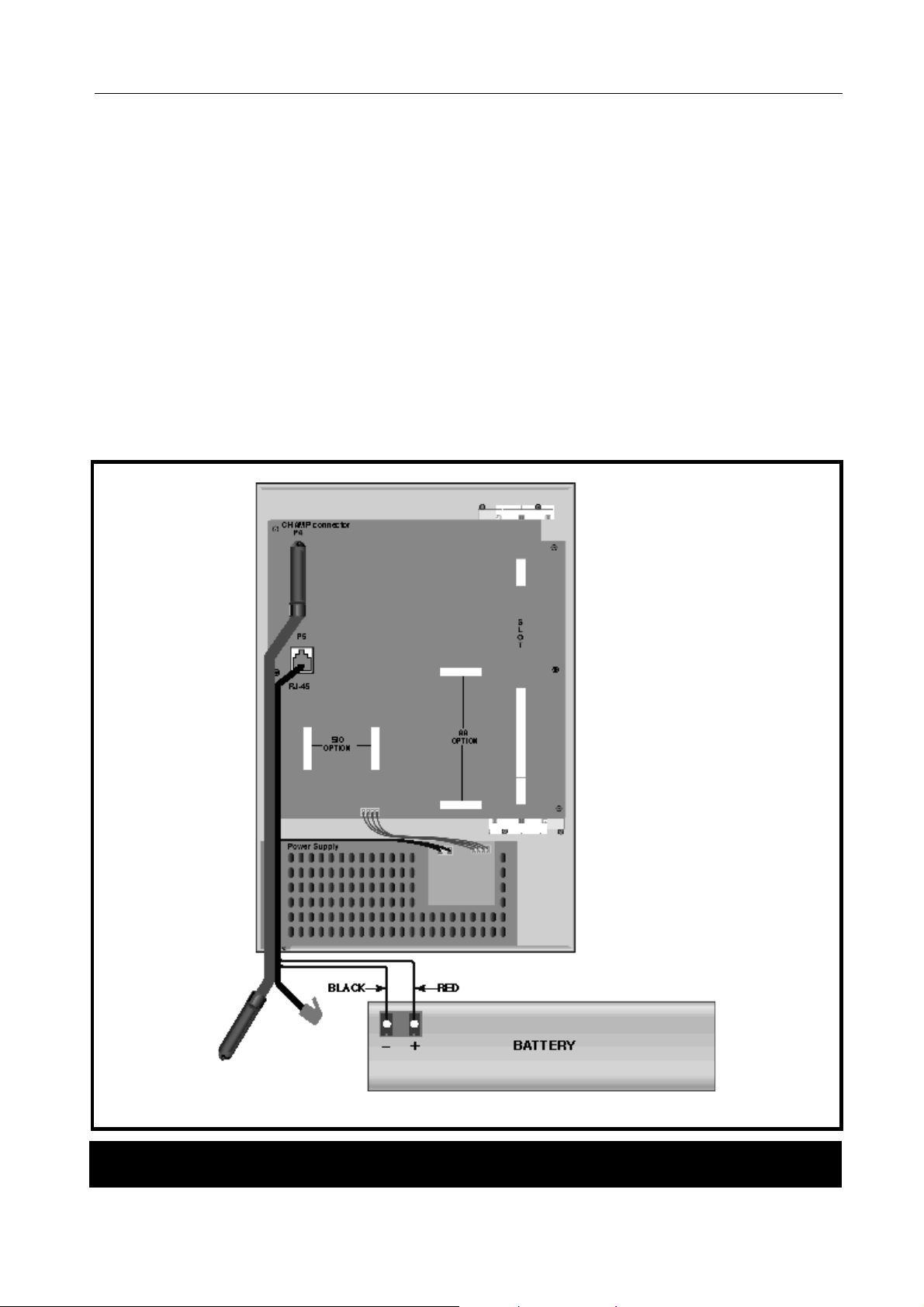
2.6 EXTERNAL BATTERY CONNECTION
See (Figure 2-3)
A socket is provided on the KSU for c onnection of an external battery for system during AC power f ailur e.
The DCS-24 system is equipped with a battery charging and a discharging circuit to interface with an
external battery.
The capacity of a backup battery must be 48 volts and should be rated at greater than 6AH and less than
26AH. The DCSBBU backup battery is rated at 7AH.
To connect an external battery use the connection plug and cable supplied, and connect the RED wire
lead of the cable to the positive (+) term inal of the battery and the BLACK wire lead to the negative (-)
terminal. The plug should be inserted into the socket in the power supply.
Note that the actual connection should be done as the final step in the installation process.
Figure 2-3
!
USE EXTREME CAUTION
TO ENSURE THAT THE
POLARITY IS CORRECT
AND THAT THE CHARGING
CURRENT IS NOT
EXCESSIVE
Connecting a System Backup Batter
6
Page 10

DCS 24 MARCH 1999
INSTALLATION MANUAL
2.7 SELECTING OPTIONS ON THE BASIC KSU
See figure 2-4.
There are some har dware options to select in the Basic KSU; Memor y Backup Selection, Music Source
Selection and MPD/ PRS selection for the two (2) analogue trunk lines on the Base board.
2.7.1 MEMORY BACKUP SELECTION
The system is equipped with data memory, 256Kbyte and memory backup circuitry (a super capacitor) to
protect customer data in case of any power failure. The memory backup circuitry has a shunt-pin switch
to toggle enabling backup. Before shipment, the switch is selected OFF to prevent the super capacitor
from discharging during shipment and storage and it should be moved to ON after installing and
programming the system. If this is not done, the customer data will be lost in the event of power failure.
2.7.2 MUSIC SOURCE SELECTION
The Basic KSU is equipped with a melody chip to provide mu sic to stations and trunk lines as Mus ic-onHold or Background mu sic. In addition, an interface is provided for an ex ternal music source suc h as a
CD player or a radio etc.
The system provides a single music channel for Music-on-Hold or Background music. Reference should
be made to Figure 2-5 for the selection of the music source at the end of installation - a shunt-pin switch
is used to select the music source between the internal melody chip or an external music source.
The connection of the external music source is explained in Part 6.
2.7.3 MPD/ PRS SELECTION AND INSTALLATION
Both the two analogue trunk interfaces mounted on the KSU motherboard have positions for a single
hybrid (MPD-HYB or PRS-HYB) for each exchange line. The m otherboard is supplied r eady for use with
MPD hybrids; ie. the hybrid sockets are connected to line via dec oupling capacitors. The motherboard
must be modified before PRS hybrids can be used. This modification involved soldering a wire link
across the decoupling capacitors used for the MPD so that the PRS hybrid is connected directly to the
line. Capacitors C214 and C215 relate to TRK1, and C224 and C225 relate to TRK 2. Figure 2-5
indicates the hybrid insertion sockets. Ens ure that the chips are f irmly inserted in the sock ets - one chip
per line.
7
Page 11

DCS 24 MARCH 1999
Selecting Options On the Basic KSU
INSTALLATION MANUAL
MUSIC
SOURCE
EXT
INT
MPD/PRS
SOCKET
FOR TRK1
MPD/PRS
SOCKET
FOR TRK2
MEMORY
BACKUP
ON
OFF
-
8
Page 12

DCS 24 MARCH 1999
INSTALLATION MANUAL
3 INSTALLING OPTION BOARDS AND TRUNK CARDS
(Figure 3-1)
Unpack and inspect each card for physical damage before installation. Contact the supplier if any damage to
the card is detected. Do not attempt to install a damaged card.
WARNING
components. To reduce the incidence of premature equipment failure, observe the
• Always discharge static from yourself before handling any Printed Board Assemblies (PBA’s) and wear
an anti-static wrist strap connected to the KSU earth lug.
• Always handle boards by the edges.
• Never touch PBA tracks or connectors. Contaminants introduced by fingers can cause corrosion and
high resistance connections.
• Never touch or straighten components, especially the ceramic sub-assemblies. They are physically
delicate and finger pressure can fracture component leads (even if the leads do not actually break).
• To protect PBAs against physical damage and damage due to static discharge, always wrap them in
an anti-static bag and replace them in the packaging provided with the new item.
Power must be switched OFF before any cards are removed or installed.
. The Samsung DCS 24 system contains many static sensitive
following precautions -
WARNING
9
Page 13

DCS 24 MARCH 1999
INSTALLATION MANUAL
The DCS-24 system has one (1) trunk expansion slot for a trunk c ard and two (2) option connections for a
SIM card and AA card respectively. Figure 3-1 indicates the option board and trunk card expansion slots.
Figure 3-1
Installing Option Boards and Trunk Card
3.1 SIO OPTION BOARD
(See Figure 3-2
The DCS-24 system provides a dedicated inter face for the connection of serial interface devices. One SIM
board – 24SIM is available. The DCS 24 can house only one serial interface board.
3.1.1 24SIM Option board
Two (2) serial interfaces with DB9 connectors
There are no hardware options to select on this board. Install the card firmly and ensure that it is fully inserted
into two (2) board connectors.
10
Page 14

DCS 24 MARCH 1999
INSTALLATION MANUAL
3.1.2 24SIMCID Option board
Two (2) serial interfaces with DB9 connectors and Analogue Caller ID (FSK) decoder chip
There are no hardware options to select on this board Install the card firmly and ensure that it is f ully inserted
into the two (2) board connectors.
ANALOGUE CID
DECODER
TWO
DB9
CONN
BOARD
CONNECTORS
AA MEMORY
BACKUP
ON - UPPER
BOARD
CONNECTORS
-
3.2 AA OPTION BOARD - AA24
Four (4) channel built-in Auto Attendant
See Figure 3-2.
A dedicated connection is provided for the fitting of the AA card. The m emory backup selection switch (a
shunt pin) should be selected to ON af ter installation. Install f irm ly and ensure that it is fully inserted into the
two (2) board connectors.
11
Page 15

DCS 24 MARCH 1999
INSTALLATION MANUAL
3.3 4TRK24 CARD
Four (4) Analogue Trunk Interfaces with Caller ID relays
See Figure 3-3.
The card has four (4) interf aces for MPD or PRS optional chips. If MPD or PRS hybrid chips are required,
these should be installed before inserting the c ard in the trunk expansion. The 4TRKCID card is supplied
ready for use with MPD hybrids; ie. the hybrid sockets are connected to line via dec oupling capac itors (2 per
line). The card must be m odified before PRS hybrids can be used. This m odification involved soldering a
wire link across the decoupling capacitors used for the MPD so that the PRS hybrid is connec ted directly to
the line. See table in 3.4 – 6TRK-CID. Install the card and ensure that it is fully inserted into the slot.
2 CAPACITORS
PER PORT
Figure 3-3
MPD/PRS SOCKETS
FOR TRK1 TO TRK6
FROM THE TOP
4TRK/6TRK and 4BRI Cards
12
Page 16

DCS 24 MARCH 1999
INSTALLATION MANUAL
3.4 6TRK24 CARD
Six (6) Analogue Trunk Interfaces with Caller ID relays
See Figure 3-3.
This card uses the sam e printed circuit board ( PCB) as the 4TRK-CID card; however, it is equipped with an
additional two trunk circuits. .The c ard has six (6) interf aces for MPD or PRS optional chips . If MPD or PRS
hybrid chips are required, these should be installed before inserting the card in the trunk expansion. The
6TRKCID card is supplied ready for use with MPD hybrids; ie. the hybrid sockets are c onnected to line via
decoupling capacitors (2 per line). The card must be modified before PRS hybrids can be used. This
modification involved soldering a wire link across the decoupling capacitors used for the MPD so that the
PRS hybrid is connected directly to the line – see the table below for details. Install the card and ensure that
it is fully inserted into the slot. Install the card and ensure that it is fully inserted into the slot.
3.4.1 MODIFYING THE 4TRK AND 6TRK CARDS FOR USE WITH PRS HYBRIDS
The cards are supplied ready for use with MPD hybrids. i.e. the hybrid sockets are connected to line via
decoupling capacitors.
Solder wire links across the capacitors on each exchange line that will be used for PRS. (Two capacitors
1.
per line - see Table below)
Insert the hybrid into the required socket on the board ensuring that hybrids are fitted with the correct
2.
orientation.
Line 4 TRK Card Capacitors 6 TRK Card Capacitors
1 C104 & C105 C104 & C105
2 C204 & C205 C204 & C205
3 C304 & C305 C304 & C305
4 C404 & C405 C404 & C405
5 C504 & C505
6 C604 & C605
3.5 ISDN 4 BASIC RATE CARD
Four (4) ISDN BRI ports
See Figure 3-3
This card is the sam e Basic Rate card as that us ed on the DCS Com pact - 4BRI-C. T here are no hardware
options to select on this card The BRI card is an optional expansion board that supports up to four BRA
Trunks and BRA extens ions. T he select ion of BRA trunk s or extens ions is via MMC 423. Note that the c ard
does not provide power to ISDN terminal equipment even when So mode is selected.
Insert the card and be assured that it is fully inserted into the slot.
The DCS 24 must be the only equipment connected to each Basic Rate line when the ISDN lines are being
used for Indial.
Standard installation procedures should be used for cable lengths, cable types and earthing when connecting
the ISDN lines from the SDF to the NT1.
13
Page 17

DCS 24 MARCH 1999
INSTALLATION MANUAL
4 POWER-UP PROCEDURE
4.1 DCS 24 POWER SUPPLY & FUSING
The DCS 24 system is shipped with the power supply already fitted to the system. The power supply includes
four fuses (Figure 4-3) which should be checked if there is a suspected power supply problem.
To remove the PSU cover to check the fuses, turn the system off at the GPO and the system ON/OFF switch
and remove the four screws fixing the power supply cover. Disconnect the cables in connectors 1 and 2,
taking care not to strain any of the wiring or connectors and remove the power supply cover. Ensure that any
replacement fuse is the same type and value as the one being replaced. (250VAC 1.6 amp for the active and
neutral mains input and 250 VAC 2 amp for the -55VDC output and Battery input)
WARNING
The DCS 24 employs fuses in both the mains ACTIVE and NEUTRAL legs. Turn
OFF the switch on the KSU and at the GPO prior to any work on the system power
supply.
4.2 POWERING UP THE SYSTEM
During the initial installation, disconnect the cables to the SDF.
Verify that the battery switch is OFF.
Power the system on and check that the green LEDS for AC and DC (above the ON/OFF switch – see Figure
4.1) on the power supply come on. The LEDs will light steady to confirm the presence of power. If the AC
LED is off and the DC LED is on this indicates the system is operating off external batteries.
Check that the RUN LED on the motherboard flashes 10s after power on. Set the BACK UP switch on the
motherboard to ON (see Figure 2.5).
4.3 POWER UP PROBLEMS
If the PSU AC LED does not illuminate the problem must be corrected before proceeding further with the
KSU installation. Follow the steps below to isolate the problem.
Turn OFF the switch on the KSU and at the GPO prior to any work on the system power
1.
supply, remove the power supply cover and check the fuses (see Figure 4.2).
Power off the system and unplug all of the cards (option cards, trunk expansion card). Power
2.
the system on again. If the PSU AC LED now illuminates, one of the cards is faulty.
If the PSU AC LED still fails to illuminate, replace the PSU. If the system still fails a replacement KSU is
3.
required.
14
Page 18

DCS 24 MARCH 1999
INSTALLATION MANUAL
Figure 4-1
Power Connections to the System
Figure 4-2
Location of Power Suppl y Fuses
15
Page 19

DCS 24 MARCH 1999
INSTALLATION MANUAL
4.4 MEMORY LED INDICATIONS
Having verified proper operation of the power supply, check the motherboard LED. The LED should flash
rapidly indicating the main processor is functioning. The battery switch should now be turned ON.
If the LED is not flashing after 10s, power off the system and replace the MEM card. If the LED still fails to
flash a replacement KSU is required.
The Memory Backup Selector s hould be moved to the ON position (See Figure 2-5). Failur e to do so may
result in a loss of programming data as well as customer data in the event of mains power failure.
4.5 DEFAULT TRUNK AND STATION NUMBERING
Upon initial power up, the CPU reads each slot for the existence of a card and identifies the type of card. It
stores this as the default configuration.
The system assigns default trunk numbers beginning with 701 upwards. The lines are numbered sequentially
from 701 upwards including both analogue exchange lines and BRI and PRI ISDN lines.
The system assigns default station numbers from 201 upwards.
Keyset daughter boards are assigned numbers from 301 upwards. For example, the daughterboard plugged
into keyset 203 will have the default number 303.
The default configuration assigns the operator position to the lowest DLI port and all incoming trunks ring that
station.
Once the cabling has been completed, the keysets, exchange lines and single line telephones should be
tested for correct operation.
Station and trunk numbers can be changed, rearranged and reassigned as required using system
programming.
5 DCS 24 System Cabling
5.1 SAFETY PRECAUTIONS
To limit the risk of personal injury, always follow these precautions before connecting analogue and digital
exchange line circuits and ODX circuits :
• Never install telephone wiring during a lightning storm.
• Never install telephone jacks in a wet location unless the jack is specifically designed for wet locations.
• Never touch uninsulated telephone wires or terminals unless the line has been disconnected at the
network interface.
• Use caution when installing or modifying telephone lines.
5.2 SYSTEM CABLING
All connections to the DCS 24 system are made by way of a system distribution frame (SDF) except for the
240VAC power and back-up battery. All cabling to and from the SDF should be made using ACA approved
0.4mm or 0.5mm twisted pair cable.
Refer to Chapter 9 of DCS I&M manual for details of maximum cable lengths
16
Page 20

DCS 24 MARCH 1999
INSTALLATION MANUAL
The main connection from the KSU to the SDF uses a cable assembly terminated with an AMP-Champ type
connector on one end and a 10 Pair Krone connector on the other. The AMP-Champ connector inserts into a
socket on the KSU. The cable assemblies can be customer-supplied or are available as items supplied with
the systems.
The first 20 pins of the AMP Champ connector are assigned to connections of trunk interfaces on a trunk
interface card as well as on the Base board, the next 6 pins are for connections of miscellaneous circuits and
the last 24 pins are assigned to connections of 12 DLI ports on the Base board. Refer to tables below. The
retaining screw on the Champ connector should be secured to hold the connector in place on the KSU.
Connection for the SLT’s is via a 4-pair modular jack (RJ-45) on the motherboard.
5.2.1 CABLE TAIL DESCRIPTION
PART NUMBER
S25-44 25 Pair Tail Assembly - 1 Amp Champ, 3
DESCRIPTION
Krone Connectors.
USE
Connects to KSU Motherboard
17
Page 21

DCS 24 MARCH 1999
INSTALLATION MANUAL
5.3 DCS 24 DISTRIBUTION FRAME CIRCUIT ALLOCATION
25 Pair Tail
5.3.1 TRUNK CARD CONNECTIONS
Amp
Pins
26,1 1 1 Trunk 1* Not Used White - Blue
27,2 1 2 Trunk 2* Not Used White - Orange
28,3 1 3 Trunk 3 Port 1Tx+, Tx- (to NTU) White - Green
29,4 1 4 Trunk 4 Port 1 Rx+, Rx- (from NTU) White - Brown
30,5 1 5 Trunk 5 Port 2Tx+, Tx- (to NTU) White - Slate
31,6 1 6 Trunk 6 Port 2 Rx+, Rx- (from NTU) White - Blue\White
32,7 1 7 Trunk 7 Port 3Tx+, Tx- (to NTU) White - Blue\Orange
33,8 1 8 Trunk 8 Port 3 Rx+, Rx- (from NTU) White - Blue\Green
34,9 1 9 Not Used Port 4Tx+, Tx- (to NTU) White - Blue\Brown
35,10 1 10 Not Used Port 4 Rx+, Rx- (from NTU) White - Blue\Slate
36,11 2 1 Not Used Not Used White - Orange\White
37,12 2 2 Not Used Not Used White - Orange\Green
38,13 2 3 Not Used Not Used White - Orange\Brown
Krone
Module
Krone
Module
Pair
Circuit Colour
4TRK / 6TRK 4BRI
39,14 2 4 Not Used Not Used White - Orange\Slate
40,15 2 5 Not Used Not Used White - Green\White
41,16 2 6 Not Used Not Used White - Green\Brown
42,17 2 7 Not Used Not Used White - Green\Slate
43,18 2 8 Not Used Not Used White - Brown\White
44,19 2 9 Not Used Not Used White - Brown\Slate
45,20 2 10 Not Used Not Used White - Slate\White
46,21 3 1 Not Used Not Used Yellow - Blue
47,22 3 2 Not Used Not Used Yellow - Orange
48,23 3 3 Not Used Not Used Yellow - Green
49,24 3 4 Not Used Not Used Yellow - Brown
50,25 3 5 Not Used Not Used Yellow - Slate
*Trunk 1 and Trunk 2 circuits are located on the KSU motherboard and provide power fail transfer to
extensions 15 and 16 respectively
# 6TRK Card Only
18
Page 22

DCS 24 MARCH 1999
INSTALLATION MANUAL
5.3.2 DLI AND OPTIONAL EQUIPMENT CONNECTIONS
Amp
Pins
26,1 1 1 Not Used Not Used White - Blue
27,2 1 2 Not Used Not Used White - Orange
28,3 1 3 Not Used Not Used White - Green
29,4 1 4 Not Used Not Used White - Brown
30,5 1 5 Not Used Not Used White - Slate
31,6 1 6 Not Used Not Used White - Blue\White
32,7 1 7 Not Used Not Used White - Blue\Orange
33,8 1 8 Not Used Not Used White - Blue\Green
34,9 1 9 Not Used Not Used White - Blue\Brown
35,10 1 10 Not Used Not Used White - Blue\Slate
36,11 2 1 Not Used Normally Open Contact White - Orange\White
Krone
Module
Krone
Module
Pair
Circuit Colour
DLI Other
37,12 2 2 Not Used Paging Output White - Orange\Green
38,13 2 3 Not Used External MOH White - Orange\Brown
39,14 2 4 DLI Port 1 Not Used White - Orange\Slate
40,15 2 5 DLI Port 2 Not Used White - Green\White
41,16 2 6 DLI Port 3 Not Used White - Green\Brown
42,17 2 7 DLI Port 4 Not Used White - Green\Slate
43,18 2 8 DLI Port 5 Not Used White - Brown\White
44,19 2 9 DLI Port 6 Not Used White - Brown\Slate
45,20 2 10 DLI Port 7 Not Used White - Slate\White
46,21 3 1 DLI Port 8 Not Used Yellow - Blue
47,22 3 2 DLI Port 9 Not Used Yellow - Orange
48,23 3 3 DLI Port 10 Not Used Yellow - Green
49,24 3 4 DLI Port 11 Not Used Yellow - Brown
50,25 3 5 DLI Port 12 Not Used Yellow - Slate
19
Page 23

DCS 24 MARCH 1999
INSTALLATION MANUAL
5.4 DETAILS OF THE RJ45 CONNECTIONS
Eight pins of the RJ-45 connector are assigned to connections of Single Line telephone interface ports on the
Base board.
Pin No. Circuits/ Functions Remark
1
8
2
7
3
6
4
5
SLT Port 1 No polarity
SLT Port 2 No polarity
SLT Port 3 No polarity
SLT Port 4 No polarity
20
Page 24

DCS 24 MARCH 1999
INSTALLATION MANUAL
6 CONNECTING STATION AND OPTIONAL EQUIPMENT
The
DCS and Compact Installation Manual Chapter 9
• Keysets, Add On Modules, SLT’s, Door Phone and Headsets,
provides connection information for the following
:
In addition, general information is provided for:
• MOH, External Paging, Common Bell, Ring Over Page,
Information is also provided for:
• SMDR and PCMMC and Remote Programming.
The following provides additional information:
6.1 MUSIC ON HOLD
The DCS-24 system provides for one MOH source – either from the built-in melody chip (Internal) or an
external music source, i.e. CD player or radio. Figure 2.5 indicates the position of the Internal/External
switch. An external source is wired via the SDF – Krone Module 2, 3
rd
pair
6.2 EXTERNAL PAGING
The DCS-24 system is equipped with an interface for connection to custom er-supplied paging equipment.
The interface is designed to m atch 600 ohm and an im pedance m atching transf orm er m ay be required if the
impedance of the paging equipment is not 600 ohm. Connection is via the Krone Module 2, Pair 2.
6.3 COMMON BELL
A customer-provided loud r inging device can be c ontrolled by the general purpos e dry contact of the DCS-24
system by means of relevant MMC. Note that the dry contact is rated 24VDC, 1 Ampere. The system
requires MDF connection for the dr y contact and the connection can be through the champ connector. See
Figure 2-3 and refer to the section 2.5 (MDF Cabling).
6.4 RING OVER PAGE
When a custom er-provided paging system is installed, incoming c alls can be assigned to Ring Over Page
(ROP). By means of relevant MMC, program a line or lines to ring a hunt group and assign ROP as a
destination in this hunt group. Ring over Page can be used for day or night operation or both. Refer to the
programming manual.
21
Page 25

DCS 24 MARCH 1999
)
)
)
)
)
)
)
)
)
INSTALLATION MANUAL
6.5 STATION MESSAGE DETAIL RECORDING (SMDR)
(See Figure 6-1)
To receive an SMDR printout, connect a cus tomer-provided printer to one of the serial interfac e connectors
(DB9) on the SIM24 SIO option board (See Figure 3-2).
device or the DCS24 system, before connecting the printer or the call accounting device, ensure that
the system power is turned OFF. Any external battery if installed should also be removedl.
In order to prevent damage to the external
SIO BOARD (DTE DB9) PRINTER (DTE DB25)
RXD (2
TXD (3
GND (5
DSR (6
DCD (1
"
CONNECT A PRINTER OR A CALL ACCOUNTING
DEVICE TO ONE OF DB9 CONNECTORS ON AN SIO
OPTION BOARD
NOTE THAT SYSTEM POWER SHOULD BE REM OVED
BEFORE CONNECTING THE DEVICE.
"
DSR (6) MAY BE REPLACED WITH DCD (1) IN CASE
THE PRINTER CANNOT WORK WITH DSR.
TXD (2
RXD (3
GND (7
DTR (20
PIN CONNECTIONS TO PRINTER
Use a pin to pin RS232C cable. Only pins 2, 3, 5 and 6 are required. When the printer or optional call
accounting device needs to be more than 5 meters away from the system, shielded computer cable is
required. Connect a male DB9 connector to the SIO board and then connect a connector that meets the
requirement of the printer or the call accounting device to the other end. The cable must not exceed 100
meters.
-
22
Page 26

DCS 24 MARCH 1999
)
)
)
)
)
)
)
)
)
)
)
)
)
)
)
)
)
)
)
)
)
)
INSTALLATION MANUAL
6.6 PC PROGRAMMING
(See Figure 6-2)
To program the system via a personal computer (PC), connect a PC equipped with the proprietary program ,
PCMMC to one of the serial interface connec tors (D B9) on an SIO option board ( See Figure 3- 2) .
prevent damage to the PC or the DCS24 system, before conn ectin g PC, en sure t hat th e system power
is turned OFF. Any external battery if installed should also be removed
.
In order to
SIO BOARD (DTE DB9) PC (DTE DB25 or DB9)
RXD (2
TXD (3
GND (5
DCD (1
RTS (7
DTR (4
DSR (6
DCD (1
"
CONNECT A PC EQUIPPED WITH PCMMC TO ONE OF DB9 CONNECT ORS ON AN
SIO OPTION BOARD. NOTE THAT SYSTEM POWER SHOULD BE REMOVED
BEFORE CONNECTING THE DEVICE.
"
DCD (1) MAY REPLACE DSR (6) FOR A SPECIFIC EQUIPMENT
TXD (2
RXD (3
GND (7
RTS (4
CTS (5
DSR (6
DTR (20
DB25 DB9
TXD (3
RXD (2
GND (5
RTS (7
CTS (8
DSR (6
DTR (4
PIN CONNECTIONS TO PC
Use a pin to pin RS232C cable. Only pins 2, 3, 4, 5, and 6 are required. When the personal computer needs
to be more than 5 meters away from the system, shielded computer cable is required. Connect a male DB9
connector to the SIO board and then connect a connector that meets the requirement of the personal
computer to the other end. The cable must not exceed 100 meters.
The signal DCD (1) and RTS (7) are optional - the system does not refer to the signal status. For some
equipment, the DSR (6) may not detect the DTR signal from the external device. In this case, connect the
DTR signal wire to the DCD(pin 1) of the DCS-24 serial interface.
23
-
Page 27

DCS 24 MARCH 1999
)
)
)
)
)
)
)
)
)
)
)
)
)
)
INSTALLATION MANUAL
6.7 REMOTE PROGRAMMING
(See Figure 6-3)
To remotely program the system , connect a custom er-provided m odem to one of serial interface c onnectors
(DB9) on an SIO option board (See Figure 3-1 and Figure 3-2) . Before connecting the modem , be assured
that the system power is turned OFF. ).
before connecting PC, ensure that the system po wer is turned OFF . Any external battery if installed
should also be removed
.
In order to prevent damage to t he modem or th e DCS24 system,
SIO BOARD (DTE DB9) MODEM (DCE DB25)
RXD (2
TXD (3
GND (5
DCD (1
RTS (7
DTR (4
DSR (6
TXD (3
RXD (2
GND (7
DCD (1
CTS (4
DTR (20
DSR (6
"
CONNECT A PC EQUIPPED WITH PCMM C TO ONE OF
DB9 CONNECTORS ON AN SIO OPTION BOARD.
NOTE THAT SYSTEM POWER SHOULD BE REM OVED
BEFORE CONNECTING THE DEVICE.
PIN CONNECTIONS TO MODEM
Use a pin to pin RS232C cable. Only pins 2, 3, 4, 5, 6, 7 and 8 are required. When the modem needs to be
more than 5 meters away from the system, shielded computer cable is required. Connect a male DB9
connector to the SIO board and then connect a connector that meets the requirement of the modem to the
other end. The cable must not exceed 100 meters.
6.8 POWER FAILURE TRANSFER
When the system loses AC power and has no external battery, the two (2) analogue trunk lines on the Base
board are automatically switched to the last two (2) stations.
st
Trunk line to Station 15 (SLT)
1
nd
Trunk line to Station 16 (SLT)
2
24
-
Page 28

DCS 24 MARCH 1999
INSTALLATION MANUAL
7 CHANGING SOFTWARE
(See Figure 7-1)
7.1 ACCESSING THE EPROM’S
The system software is contained on the motherboard. This procedure should be performed in the following
sequence -
1. Check that the battery switch on the motherboard is ON.
. If the documentation with the new software indicates that reprogramming will be necessary, the battery
Note
switch may be switched OFF at this stage to ensure the system is properly returned to default data.
2. Switch off the KSU and remove plug of battery back-up cable. If used
the GPO
7.1.1 REPLACING THE EPROMS
1. Remove the four EPROMs using a suitable IC extraction tool and set them aside in case they need to
be re-installed.
2. Remove the four new EPROMs from their protective packaging and check that the legs are straight
and undamaged. Damaged EPROMs should be returned to the supplier and replaced with an
undamaged firmware set
3. Carefully insert the new EPROMs, commencing with the one closest the Power Supply (ODD2) into the
designated sockets. The new EPROMs are labelled with EV-1, OD-1, EV-2 and OD-2. The EPROM
positions are marked on the motherboard adjacent to each IC socket. Refer to Figure 7-1.
4. Switch on the KSU and verify that the system is operating. If the KSU does not operate, remove the
new EPROMs, re-install the old EPROMs and test again.
5. When the system is operating correctly switch ON the battery switch on the motherboard and replace
the cover.
.
. Do not unplug the KSU from
25
Page 29

DCS 24 MARCH 1999
INSTALLATION MANUAL
U703
ODD
1
U704
EVEN
1
U705
ODD
2
U706
EVEN
2
Figure 7-1
Location of EPROM’s
26
 Loading...