

SAMSUNG CW29M064VPXXEC, CW29M064NPXXEC, CS21S8MH3C-ABS, CS21A11MH4SGAR, CS21A11MH3CABS Service Manual
COLOR TELEVISION RECEIVER
Chassis : S56A(P) Rev.1
Model: CW29M064VPXXEC
CW29M064NPXXEC
CS21S8MH3C/ABS
CS21A11MH4SGAR
CS21A11MH3CABS
COLOR TELEVISION RECEIVER CONTENTS
Precautions
Reference Information
Specifications
Alignment and Adjustments
Troubleshooting
Exploded Views and Parts List
Electrical Parts List
Block Diagrams
Wiring Diagram
Schematic Diagrams
1.
2.
3.
4.
5.
6.
7.
8.
9.
10.
1. Precautions
1-1 Safety Precautions
1. Be sure that all of the built-in protective
devices are replaced. Restore any missing
protective shields.
2. When reinstalling the chassis and its
assemblies, be sure to restore all protective
devices, including: nonmetallic control knobs
and compartment covers.
3. Make sure that there are no cabinet openings
through which people—particularly
children—might insert fingers and contact
dangerous voltages. Such openings include
the spacing between the picture tube and the
cabinet mask, excessively wide cabinet
ventilation slots, and improperly fitted back
covers.
If the measured resistance is less than 1.0
megohm or greater than 5.2 megohms, an
abnormality exists that must be corrected
before the unit is returned to the customer.
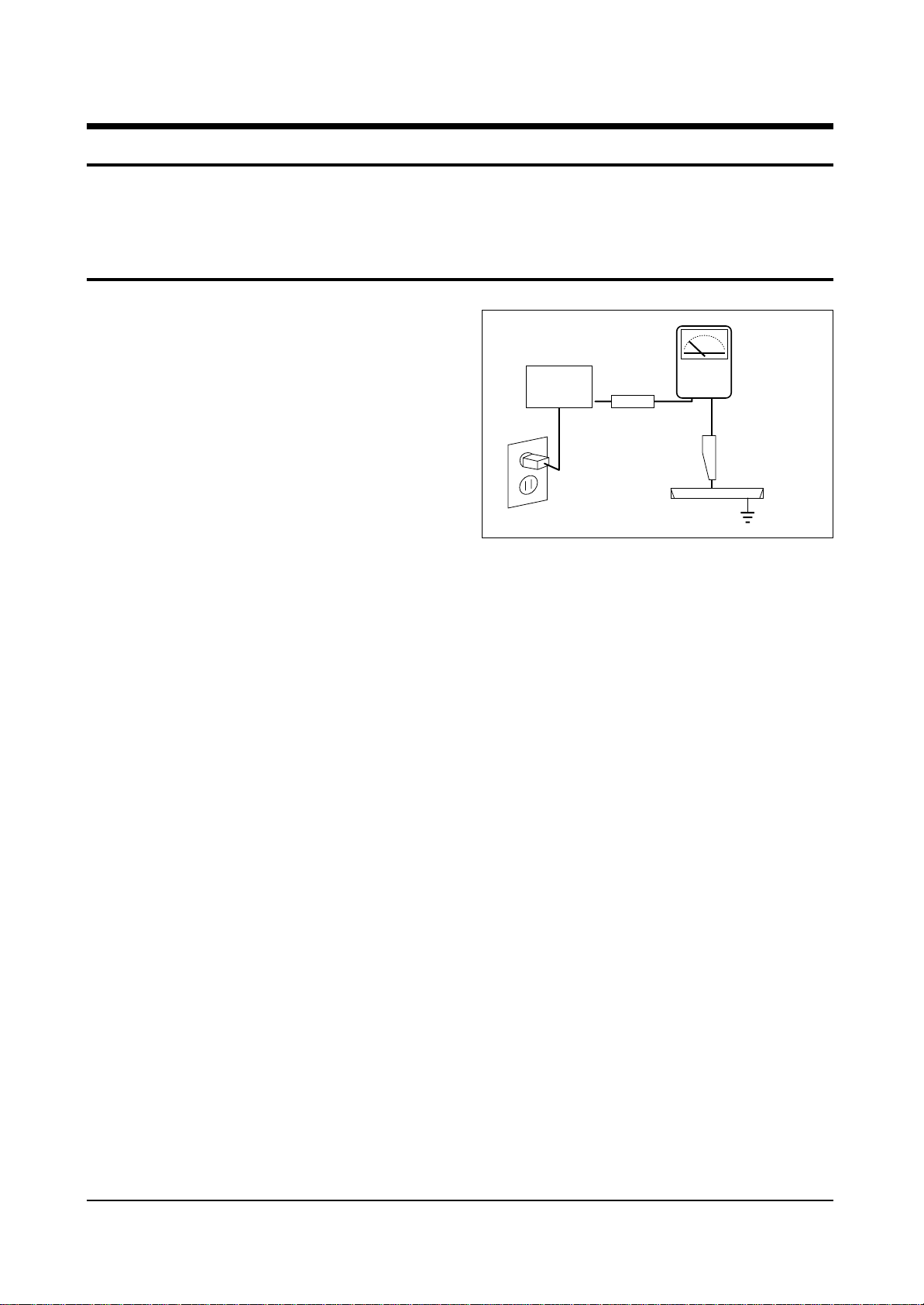
4. Leakage Current Hot Check (Figure 1-1):
Warning: Do not use an isolation
transformer during this test. Use a leakagecurrent tester or a metering system that
complies with American National Standards
Institute (ANIS C101.1, Leakage Current for
Appliances), and Underwriters Laboratories
(UL Publication UL1410, 59.7).
5. With the unit completely reassembled, plug
the AC line cord directly into the power
outlet. With the unit’s AC switch first in the
ON position and then OFF, measure the
current between a known earth ground (metal
water pipe, conduit, etc.) and all exposed
metal parts, including: antennas, handle
brackets, metal cabinets, screwheads and
control shafts. The current measured should
not exceed 0.5 milliamp. Reverse the powerplug prongs in the AC outlet and repeat the
test.
Fig. 1-1 AC Leakage Test
6. Antenna Cold Check:
With the unit’s AC plug disconnected from the
AC source, connect an electrical jumper across
the two AC prongs. Connect one lead of the
ohmmeter to an AC prong. Connect the other
lead to the coaxial connector.
7. X-ray Limits:
The picture tube is especially designed to
prohibit X-ray emissions. To ensure continued
X-ray protection, replace the picture tube only
with one that is the same type as the original.
Carefully reinstall the picture tube shields and
mounting hardware; these also provide X-ray
protection.
8. High Voltage Limits:
High voltage must be measured each time
servicing is done on the B+, horizontal
deflection or high voltage circuits.
Correct operation of the X-ray protection
circuits must be reconfirmed whenever they
are serviced.
(X-ray protection circuits also may be called
“horizontal disable” or “hold-down”.)
Heed the high voltage limits. These include
the X–ray Protection Specifications Label, and
the Product Safety and X-ray Warning Note on
the service data schematic.
Precautions
Samsung Electronics 1-1
LEAKAGE
CURRENT
TESTER
DEVICE
UNDER
TEST
TEST ALL
EXPOSED METAL
SURFACES
2-WIRE CORD
ALSO TEST WITH
PLUG REVERSED
(USING AC ADAPTER
PLUG AS REQUIRED)
EARTH
GROUND
(READING SHOULD
NOT BE ABOVE
0.5mA)
Follow these safety, servicing and ESD precautions to prevent damage and protect against potential
hazards such as electrical shock and X-rays.

1-1 Safety Precautions (Continued)
9. High voltage is maintained within specified
limits by close-tolerance, safety-related
components and adjustments. If the high
voltage exceeds the specified limits, check
each of the special components.
10. Design Alteration Warning:
Never alter or add to the mechanical or
electrical design of this unit. Example: Do not
add auxiliary audio or video connectors. Such
alterations might create a safety hazard. Also,
any design changes or additions will void the
manufacturer’s warranty.
11. Hot Chassis Warning:
Some TV receiver chassis are electrically
connected directly to one conductor of the AC
power cord. If an isolation transformer is not
used, these units may be safely serviced only
if the AC power plug is inserted so that the
chassis is connected to the ground side of the
AC source.
To confirm that the AC power plug is inserted
correctly, do the following: Using an AC
voltmeter, measure the voltage between the
chassis and a known earth ground. If the
reading is greater than 1.0V, remove the AC
power plug, reverse its polarity and reinsert.
Re-measure the voltage between the chassis
and ground.
12. Some TV chassis are designed to operate with
85 volts AC between chassis and ground,
regardless of the AC plug polarity. These units
can be safely serviced only if an isolation
transformer inserted between the receiver and
the power source.
13. Some TV chassis have a secondary ground
system in addition to the main chassis ground.
This secondary ground system is not
isolated from the AC power line. The two
ground systems are electrically separated by
insulating material that must not be defeated
or altered.
14. Components, parts and wiring that appear to
have overheated or that are otherwise
damaged should be replaced with parts that
meet the original specifications. Always
determine the cause of damage or
overheating, and correct any potential
hazards.
15. Observe the original lead dress, especially
near the following areas: Antenna wiring,
sharp edges, and especially the AC and high
voltage power supplies. Always inspect for
pinched, out-of-place, or frayed wiring. Do
not change the spacing between components
and the printed circuit board. Check the AC
power cord for damage. Make sure that leads
and components do not touch thermally hot
parts.
16. Picture Tube Implosion Warning:
The picture tube in this receiver employs
“integral implosion” protection. To ensure
continued implosion protection, make sure
that the replacement picture tube is the same
as the original.
17. Do not remove, install or handle the picture
tube without first putting on shatterproof
goggles equipped with side shields. Never
handle the picture tube by its neck. Some
“in-line” picture tubes are equipped with a
permanently attached deflection yoke; do not
try to remove such “permanently attached”
yokes from the picture tube.
18. Product Safety Notice:
Some electrical and mechanical parts have
special safety-related characteristics which
might not be obvious from visual inspection.
These safety features and the protection they
give might be lost if the replacement
component differs from the original—even if
the replacement is rated for higher voltage,
wattage, etc.
Components that are critical for safety are
indicated in the circuit diagram by shading,
( ) or ( ).
Use replacement components that have the
same ratings, especially for flame resistance
and dielectric strength specifications.
A replacement part that does not have the
same safety characteristics as the original
might create shock, fire or other hazards.
Precautions
1-2 Samsung Electronics
!

1-2 Servicing Precautions
1. Servicing precautions are printed on the
cabinet. Follow them.
2. Always unplug the unit’s AC power cord from
the AC power source before attempting to:
(a) Remove or reinstall any component or
assembly, (b) Disconnect an electrical plug or
connector, (c) Connect a test component in
parallel with an electrolytic capacitor.
3. Some components are raised above the printed
circuit board for safety. An insulation tube or
tape is sometimes used. The internal wiring is
sometimes clamped to prevent contact with
thermally hot components. Reinstall all such
elements to their original position.
4. After servicing, always check that the screws,
components and wiring have been correctly
reinstalled. Make sure that the portion around
the serviced part has not been damaged.
5. Check the insulation between the blades of the
AC plug and accessible conductive parts
(examples: metal panels, input terminals and
earphone jacks).
6. Insulation Checking Procedure: Disconnect the
power cord from the AC source and turn the
power switch ON. Connect an insulation
resistance meter (500V) to the blades of the AC
plug.
The insulation resistance between each blade
of the AC plug and accessible conductive parts
(see above) should be greater than 1 megohm.
7. Never defeat any of the B+ voltage interlocks.
Do not apply AC power to the unit (or any of
its assemblies) unless all solid-state heat sinks
are correctly installed.
8. Always connect a test instrument’s ground
lead to the instrument chassis ground before
connecting the positive lead; always remove
the instrument’s ground lead last.
Precautions
Samsung Electronics 1-3
Warning1: First read the “Safety Precautions” section of this manual. If some unforeseen circumstance creates a conflict between
the servicing and safety precautions, always follow the safety precautions.
Warning2: An electrolytic capacitor installed with the wrong polarity might explode.

1. Some semiconductor (“solid state”) devices
are easily damaged by static electricity. Such
components are called Electrostatically
Sensitive Devices (ESDs); examples include
integrated circuits and some field-effect
transistors. The following techniques will
reduce the occurrence of component damage
caused by static electricity.
2. Immediately before handling any semicon
ductor components or assemblies, drain the
electrostatic charge from your body by
touching a known earth ground. Alternatively,
wear a discharging wrist-strap device. (Be
sure to remove it prior to applying power—
this is an electric shock precaution.)
3. After removing an ESD-equipped assembly,
place it on a conductive surface such as
aluminum foil to prevent accumulation of
electrostatic charge.
4. Do not use freon-propelled chemicals. These
can generate electrical charges that damage
ESDs.
5. Use only a grounded-tip soldering iron when
soldering or unsoldering ESDs.
6. Use only an anti-static solder removal device.
Many solder removal devices are not rated as
“anti-static”; these can accumulate sufficient
electrical charge to damage ESDs.
7. Do not remove a replacement ESD from its
protective package until you are ready to
install it. Most replacement ESDs are
packaged with leads that are electrically
shorted together by conductive foam,
aluminum foil or other conductive materials.
8. Immediately before removing the protective
material from the leads of a replacement ESD,
touch the protective material to the chassis or
circuit assembly into which the device will be
installed.
9. Minimize body motions when handling
unpackaged replacement ESDs. Motions such
as brushing clothes together, or lifting a foot
from a carpeted floor can generate enough
static electricity to damage an ESD.
Precautions
1-4 Samsung Electronics
1-3 Precautions for Electrostatically Sensitive Devices (ESDs)

Reference Information
Samsung Electronics 2-1
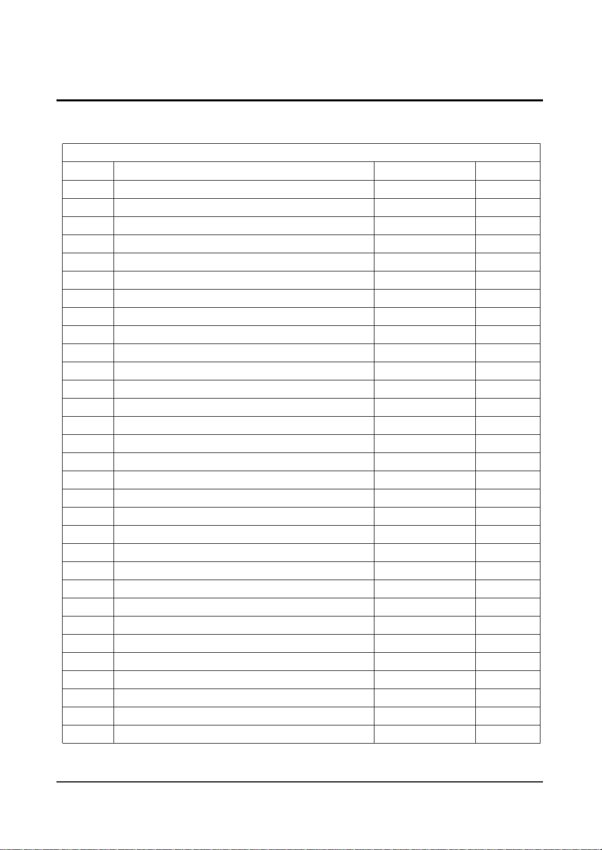
2. Reference Information
2-1 Tables of Abbreviations and Acronyms
A
Ah
Å
dB
dBm
°C
°F
°K
F
G
GHz
g
H
Hz
h
ips
kWh
kg
kHz
kΩ
km
km/h
kV
kVA
kW
I
MHz
Ampere
Ampere-hour
Angstrom
Decibel
Decibel Referenced to One
Milliwatt
Degree Celsius
Degree Fahrenheit
degree Kelvin
Farad
Gauss
Gigahertz
Gram
Henry
Hertz
Hour
Inches Per Second
Kilowatt-hour
Kilogram
Kilohertz
Kilohm
Kilometer
Kilometer Per Hour
Kilovolt
Kilovolt-ampere
Kilowatt
Liter
Megahertz
MV
MW
MΩ
m
µA
µF
µH
µm
µs
µW
mA
mg
mH
mI
mm
ms
mV
nF
Ω
pF
Ib
rpm
rps
s
V
VA
W
Wh
Megavolt
Megawatt
Megohm
Meter
Microampere
Microfarad
Microhenry
Micrometer
Microsecond
Microwatt
Milliampere
Milligram
Millihenry
Milliliter
Millimeter
Millisecond
Millivolt
Nanofarad
Ohm
Picofarad
Pound
Revolutions Per Minute
Revolutions Per Second
Second (Time)
Volt
Volt-ampere
Watt
Watt-hour
Table 2-1 Abbreviations

Reference Information
2-2 Samsung Electronics
Table 2-2 Table of Acronyms
ABL
AC
ACC
AF
AFC
AFT
AGC
AM
ANSI
APC
APC
A/V
AVC
BAL
BPF
B-Y
CATV
CB
CCD
CCTV
Ch
CRT
CW
DC
DVM
EIA
ESD
ESD
FBP
FBT
FF
FM
FS
GND
G-Y
H
HF
HI-FI
IC
IC
IF
Automatic Brightness Limiter
Alternating Current
Automatic Chroma Control
Audio Frequency
Automatic Frequency Control
Automatic Fine Tuning
Automatic Gain Control
Amplitude Modulation
American National Standards Institute
Automatic Phase Control
Automatic Picture Control
Audio-Video
Automatic Volume Control
Balance
Bandpass Filter
Blue-Y
Community Antenna Television (Cable TV)
Citizens Band
Charge Coupled Device
Closed Circuit Television
Channel
Cathode Ray Tube
Continuous Wave
Direct Current
Digital Volt Meter
Electronics Industries Association
Electrostatic Discharge
Electrostatically Sensitive Device
Feedback Pulse
Flyback Transformer
Flip-Flop
Frequency Modulation
Fail Safe
Ground
Green-Y
High
High-Frequency
High Fidelity
Inductance-Capacitance
Integrated Circuit
Intermediate Frequency
I/O
L
L
LED
LF
MOSFET
MTS
NAB
NEC
NTSC
OSD
PCB
PLL
PWM
QIF
R
RC
RF
R-Y
SAP
SAW
SIF
SMPS
S/N
SW
TP
TTL
TV
UHF
UL
UV
VCD
VCO
VCXO
VHF
VIF
VR
VTR
VTVM
TR
Input/output
Left
Low
Light Emitting Diode
Low Frequency
Metal-Oxide-Semiconductor-Field-Effect-Tr
Multi-channel Television Sound
National Association of Broadcasters
National Electric Code
National Television Systems Committee
On Screen Display
Printed Circuit Board
Phase-Locked Loop
Pulse Width Modulation
Quadrature Intermediate Frequency
Right
Resistor & Capacitor
Radio Frequency
Red-Y
Second Audio Program
Surface Acoustic Wave(Filter)
Sound Intermediate Frequency
Switching Mode Power Supply
Signal/Noise
Switch
Test Point
Transistor Transistor Logic
Television
Ultra High Frequency
Underwriters Laboratories
Ultraviolet
Variable-Capacitance Diode
Voltage Controlled Oscillator
Voltage Controlled Crystal Oscillator
Very High Frequency
Video Intermediate Frequency
Variable Resistor
Video Tape Recorder
Vacuum Tube Voltmeter
Transistor
REMARK
OPTION
OPTION
OPTION
OPTION
OPTION
OPTION
OPTION
OPTION
OPTION
OPTION
OPTION
OPTION
OPTION
OPTION
OPTION
LOC. NO
D407
D801S
D803
D805
HC101
IC201S
IC202
IC301
IC501
IC601
IC602
IC631
IC701
IC801S
IC802
IC852
ICE01
PC801S
PT801S
Q401
Q403
Q804
QE01
RL801S
SF101S
SF102S
SW801S
T401
T444S
T801S
TU01S
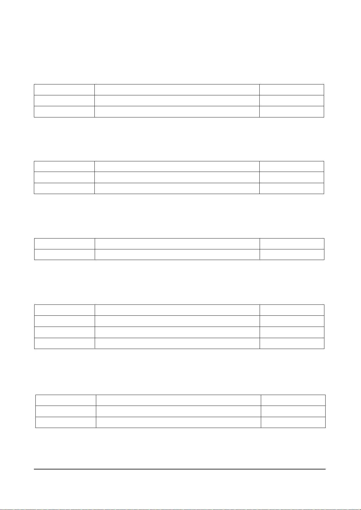
Table 2 - 3 IC Line - Up
Reference Information
Samsung Electronics 2-3
2-2 IC Line Up
SPEC
DIODE-RECTIFIER
DIODE-BRIDGE
DIODE-RECTIFIER
ASSY H/S
IC HYBRID
IC MICOM
IC-EEPROM
ASSY H/S
ASSY H/S
ASSY H/S
IC-SOUND PROCESSOR
IC-VOL, DETECTOR
IC-VIDEO SWITCH
ASSY H/S
ASSY H/S
IC-POSI.ADJUST REG.
IC-VOTAGE COMP.
PHOTO-COUPLER
THERMISTOR-PTC
ASSY H/S
TR-POWER
TR-POWER
FET-SILICON
RELAY-POWER
FILTER-SAW AV
FILTER-SAW AV
SWITCH-PUSH
TRANS-HORIZ,DRIVE
TRANS FBT
TRANS SWITCHING
TUNER
DESCRIPTION
FMP-3FU, 1.5KV, 5A, TO-3PF, ST
D5SB60, 600V, 6A, SIP-4
FMG-G2CS, 1000V, 3A, TO-220F, ST
BRIDGE, A62-00045A, D06U20S, DREAM
PAP103T, STP, 6P, PRE-AMP, TP
TDA959XPS/N1/3I, OTP, 64P, ST, SDIP
C81DC, 1028x8Bit, 8P, 100mS, 5V, PLASTIC, 10uA, CMOS
POWER, AA62-00056A, LA7845
VIDEO, AA62-30175D, TDA607Q
TDA7297, AA62-30182E
MSP3410D-CS, SDIP, 52P, 8V, 1.2W, SOUND PROCESSOR
7042, TO-92, 3P, 177MIL, PLASTIC, 4
NJM2246D, 3-INPUT, DIP, 8P, 300MIL
POWER, AA62-30181K, 5Q1265RT
POWER, AA62-30184A, KA7632
431, TO-92, 3P, 4.58MIL, PLASTIC, 2
393, DIP, 8P, 300MIL, DUAL, 36V, CMO
TR, 130-260%, 200mW, DIP-4, ST
4.50HM, +30/-20%, 220V, 290VAC, 21A, -, TR
POWER AA62-00057A, KSD5703, WASHER-TR
KSC2073-H2, NPN, 25W, TO-220, TP, 40-24
KA614, PNP, 25W, TO-220, TP, 40-24
IRF620, N, 200V, 5A, 0.8ohm, 50W, TO
12VDC, 500mW, 10A, 1FormA, 15mS, 5m
38.9MHz, SIP5K, ST, 17.9dB, B/G, D/K, I, M/N
38.9MHz, SIP5K, ST, 18dB, B/G, L/L’, M/N, 42dB
250V, 5A, DPST, -, JPW-2104B
80mH, 520uH, E119
FUH-29A001B(S), 25/29”, 130
CS21S5T, 80~280V. PM5, PL5, EER4245, 470UH, 125/16/9
TEDE9-203A, PAL, 181CH, 38.9MHz, 750ohm, DIN, ASYMM, 5V
Reference Information
2-4 Samsung Electronics
FUNCTION
Multistandard, A2 Stereo, Equalizer, 2 Scart, RCA9P
Multistandard, A2 Stereo, Nicam, Equalizer, 2 Scart, RCA9P
SPEC
TDA9592
TDA9594
FUNCTION
50Hz, W/O TTX
50Hz, With TTX 10page
REMARK
Table 2-3-1 UOC
SPEC
MSP3400D
MSP3410D
REMARK
Table 2-3-2 SOUND IC
SPEC
TDA7297
FUNCTION
15W x 2CH, 10W x 2CH, 5W x 2CH
REMARK
Table 2-3-3 SOUND AMP
SPEC
TECC0949PG35A
TEDE9-203A
TAEL-G671D
FUNCTION
Without LNA
Without LNA
With LNA
REMARK
SAMSUNG
LG
ALPS
Table 2-3-4 TUNER
SPEC
TDA6107Q
TDA6108JF
FUNCTION
25” Normal 29” Normal
21” Flat 25” Flat
REMARK
Table 2-3-5 VIDEO OUTPUT AMP
Specifications
Samsung Electronics 3-1
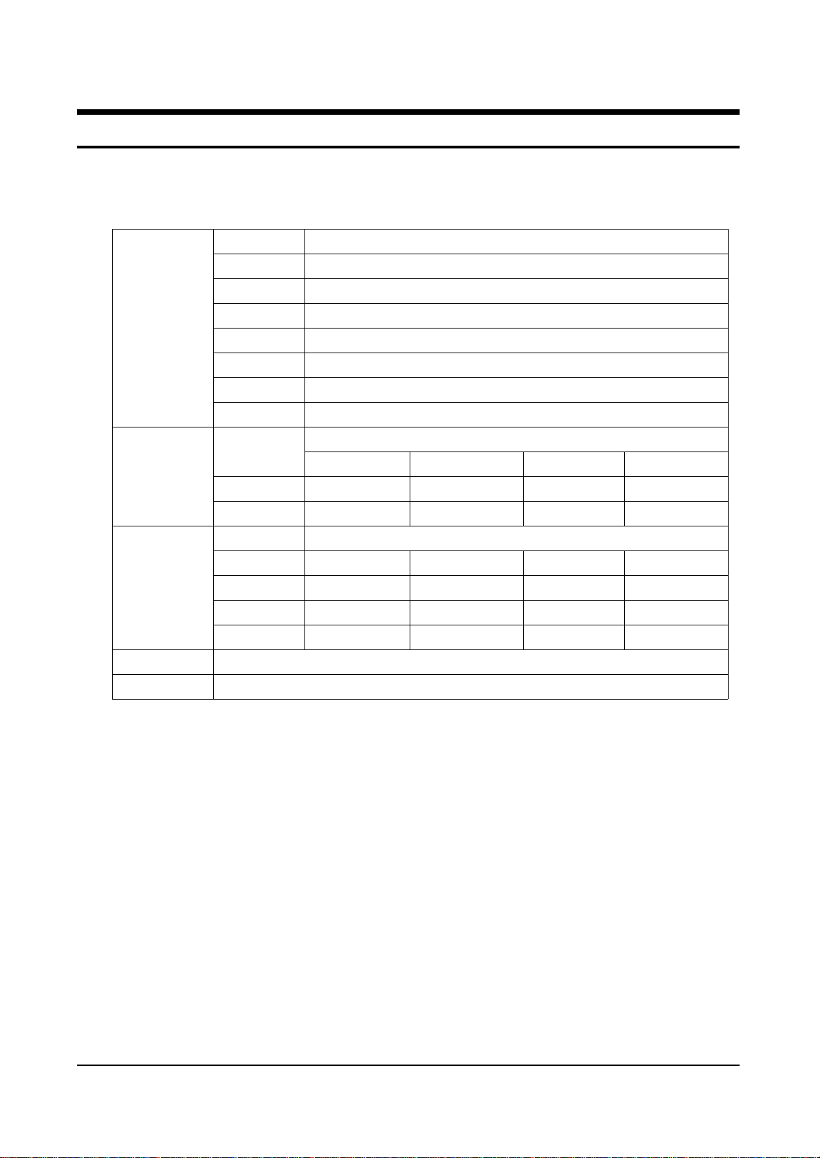
3. Specifications
Television
System
Channels
Intermediate
Frequency
Power
Antenna
CS
CZ
CW
CB
CI
CII
CX
CK
Band
VHF
UHF
IF Carrier
Frequency
Picture
Sound
Chroma
PAL, SECAM-B/G,I
02 - 12
21 - 69
PAL, SECM -B/G
38.90[MHz]
33.40[MHz]
34.47[MHz]
PAL, SECAM-B/G,I
01 - 13
21 - 69
PAL, SECAM-D/K,K1
38.90[MHz]
32.40[MHz]
34.47[MHz]
PAL, SECAM-B/G,I
02 - 09
13 - 57
PAL-I
38.90[MHz]
32.90[MHz]
34.47[MHz]
PAL, SECAM-B/G,I
02 - 13
14 - 69
NTSC-M
45.75[MHz]
41.25[MHz]
42.18[MHz]
PAL, SECAM-B/G, D/K, I, NT4.43, NT3.58
PAL, SECAM-B/G, D/K, NT4.43
PAL, SECAM-B/G, D/K, I, NT4.43, NT3.58
PAL, SECAM-B/G, D/K, I, NT4.43, NT3.58
PAL, SECAM-B/G, D/K, I, NT4.43, NT3.58
PAL, SECAM-B/G, D/K, I, NT4.43, NT3.58
PAL, SECAM-B/G, D/K, I, NT4.43, NT3.58
PAL, SECAM-B/G, D/K, I, NT4.43. NT3.58
AC100~240V, 50/60Hz
VHF, UHF : Telescopic dipole antenna)(75ohm unbalanced type)
System
System

3-2 Samsung Electronics
MEMO

Alignment and Adjustments
Samsung Electronics 4-1
4. Alignment and Adjustments
4-1 General Alignment Instructions
1. Usually, a color TV-VCR needs only slight
touch-up adjustment upon installation. Check
the basic characteristics such as height,
horizontal and vertical sync and focus.
2. Observe the picture for good black and white
details. There should be objectionable color
shading; if color shading is present,
demagnetize, perform purity and convergence
adjustments described below.
3. Use the specified test equipment or its
equivalent.
4. Correct impedance matching is essential.
5. Avoid overload. Excessive signal from a
sweep generator might overload the front-end
of the TV. When inserting signal markers, do
not allow the marker generator to distort test
results.
6. Connect the TV only to an AC power source
with voltage and frequency as specified on the
backcover nameplate.
7. Do not attempt to connect or disconnect any
wires while the TV is turned on. Make sure
that the power cord is disconnected before
replacing any parts.
8. To protect against shock hazard, use an
isolation transformer.
4-2 Automatic Degaussing
A degaussing coil is mounted around the
picture tube, so that external degaussing after
moving the TV should be unnecessary. But
the receiver must be properly degaussed upon
installation.
The degaussing coil operates for about 1
second after the power is switched ON. If the
set is moved or turned in a different direction,
the power should be OFF for at least 10
minutes.
If the chassis or parts of the cabinet become
magnetized, poor color purity will result. If
this happens, use an external degaussing coil.
Slowly move the degaussing coil around the
faceplate of the picture tube and the sides and
front of the receiver. Slowly withdraw the coil
to a distance of about 6 feet before turning
power OFF.
If color shading persists, perform the
following Color purity and Convergence
adjustments.
4-3 High Voltage Check
CAUTION : There is no high voltage adjustment
on this chassis. The B+ power supply should be
+135 volts (with full color- bar input and normal
picture level).
1. Connect a digital voltmeter to the second
anode of the picture tube.
2. Turn on the TV. Set the Brightness and
Contrast controls to minimum (zero beam
current).
3. Adjust the Brightness and contrast controls to
both extremes. Ensure that the high voltage
does not exceed 30 KV under any conditions.
Alignment and Adjustments
4-2 Samsung Electronics
4-4 FOCUS Adjustment
1. Iput a black and white signal.
2. Adjust the tuning control for the clearest picture.
3. Adjust the FOCUS control for well defined scanning lines in the center area of the screen.
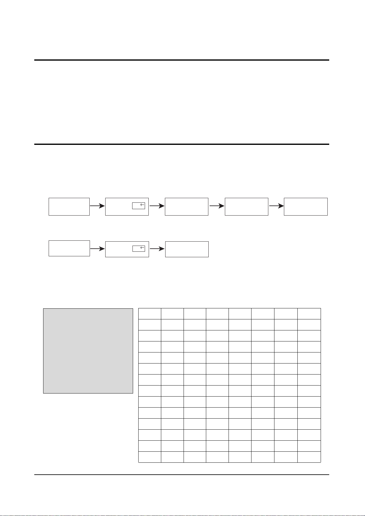
4-5 Factory Adjustment
1. To enter the “Service Mode”, Press the remote-control keys in this sequence :
- If you do not have Factory remote-control
- If you have Factory remote-control
4-5-1 Service Mode
4-5-2 Factoy Mode OSD
ADJUST
OPTION 52 2A 48
G2-ADJUST
RESET
SPM-836EAN 2002/02/08
AGC
SCT
SBT
BLR
BLB
RG
GG
BG
VSL
VS
VA
HS
SC
CDL
33
13
9
31
27
32
25
31
19
38
40
30
24
9
STT
AKB
PDL
NDL
PSR
NSR
VOL
LCO
TXP
MVOL
FMWS
AGCS1
OMD
SCL
7
0
15
10
15
10
10
0
9
10
0
1
26
1
PWL
AGN
PEK
ACL
FCO
SCBT
SSP
PSNS
HPAR
HBOW
EWID
EPAR
EUCN
ELCN
12
1
2
0
0
45
20
1
32
32
32
32
32
32
ETRP
VZ
SVM
VMA
DPSR
DNSR
DSBT
DCDL
DBLR
DBLB
32
58
0
0
15
10
7
9
31
27
4-5-2(A) ADJUST
PICTURE OFF PICTURE ON
PICTURE ON
DISPLAY
DISPLAY
()
()
MENU
FACTORY
MUTE
Alignment and Adjustments
Samsung Electronics 4-3
OSD
AGC
SCT
SBT
BLR
BLB
RG
GG
BG
VSL
VS
VA
HS
SC
CDL
STT
AKB
PDL
NDL
PSR
NSR
VOL
LCO
TXP
MVOL
FMWS
AGCS1
OMD
SCL
PWL
AGN
PEK
ACL
FCO
SCBT
SSP
Range
0 ~ 63
0 ~ 23
0 ~ 23
0 ~ 63
0 ~ 63
0 ~ 63
0 ~ 63
0 ~ 63
0 ~ 63
0 ~ 63
0 ~ 63
0 ~ 63
0 ~ 63
0 ~ 15
0 ~ 7
0 ~ 1
0 ~ 15
0 ~ 15
0 ~ 23
0 ~ 23
0 ~ 63
0 ~ 1
0 ~ 15
0 ~ 50
0 ~ 1
0 ~ 3
0 ~ 63
0 ~ 3
0 ~ 15
0 ~ 1
0 ~ 3
0 ~ 1
0 ~ 1
0 ~ 63
0 ~ 23
Register
1Eh(D5-D0)
1Dh
1Bh
14h(D5-D0)
15h(D5-D0)
16h(D5-D0)
17h(D5-D0)
18h(D5-D0)
0Fh(D5-D0)
12h(D5-D0)
10h(D5-D0)
09h(D5-D0)
0Fh(D5-D0)
2Ah(D3-D0)
08h
2Ah(D4)
1Ah(D3-D0)
1Ah(D3-D0)
1Ch
1Ch
1Fh
27h(D7-D5)
87F2h(D5-D0)
Oh(D15-D0)
29h(D5)
28h(D2-D1)
05h(D5-D0)
04h(D5-D4)
04h(D3-D0)
29h(D7)
19h(D7-D6)
20h(D1)
21h(D0)
1Bh
19h(D5-D0)
Initial Value
33
13
9
31
27
32
25
31
19
38
40
30
24
9
7
0
15
10
15
10
10
0
9
10
0
1
26
1
12
1
2
0
0
45
20
Remark
RF AGC
Sub contrast(high light adjustment)
Sub brightness(low light adjustment)
Black level offset R(low light R adjustment)
Black level offset B(low light B adjustment)
White point R(high light R adjustment)
White point G(high light 25 fixed)
White point B(high light B adjustment)
Vertical slope
Vertical shift
Vertical amplitude
Horizontal shift
S-correction
Cathode drive level
Sub tint(NTSC only)
Black current stabilization
PAL Y-delay adjustment
NTSC Y-delay adjustment
PAL sub color gain adjustment
NTSC sub color gain adjustment
Initial vol adjustment
PLL demodulator frequency adjust( 0 : set )
TTX horizontal shift adjustment(Micom Memory Part)
Melody initial vol adjustment(MSP34XX)
Narrow-band sound PLL window selection
IF AGC speed
Off-set IF demodulator
Soft clipping level
Peak white limiting
FM demodulator gain
Peaking center frequency
Automatic color limiting
Forced color limiting
Screen brightness(different from INCH)
Sub Sharpness gain adjustment
Alignment and Adjustments
4-4 Samsung Electronics
OSD
PSNS
HPAR
HBOW
EWID
EPAR
EUCN
ELCN
ETRP
VZ
SVM
VMA
DPSR
DNSR
DSBT
DCDL
DBLR
DBLB
Range
0 ~ 1
0 ~ 63
0 ~ 63
0 ~ 63
0 ~ 63
0 ~ 63
0 ~ 63
0 ~ 63
0 ~ 63
0 ~ 3
0 ~ 3
0 ~ 23
0 ~ 23
0 ~ 23
0 ~ 15
0 ~ 63
0 ~ 63
Register
21h(D2)
06h(D5-D0)
07(D5-D0)
0Ah(D5-D0)
0Bh(D5-D0)
0Ch(D5-D0)
0Dh(D5-D0)
0Eh(D5-D0)
13h(D5-D0)
2Dh(D5-D0)
2Eh(D5-D0)
1Ch
1Ch
1Bh
2Ah(D3-D5)
14h(D5-D0)
15h(D15-D0)
Initial Value
1
32
32
32
32
32
32
32
32
0
0
15
10
7
9
31
27
Remark
Ident sensitivity PAL/NTSC decoder
Horizontal parallelogram
Horizontal bow
EW width
EW parabola
EW upper corner parabola
EW lower corner parabola
EW tarpezium
Vertical zoom
Delay of RGB output to VM output
Ampulitude of SVM out
DVD PAL sub color gain adjustment
DVD NTSC sub color gain adjustment
DVD Sub brightness(low light adjustment)
DVD Cathode drive level
DVD Black level offset R(low light R adjustment)
DVD Black level offset B(low light B adjustment)
Alignment and Adjustments
Samsung Electronics 4-5
ADJUST
OPTION 52 2A 48
G2-ADJUST
RESET
SPM-836EAN 2002/02/08
Item
LNA
SYSTEM
AUDIO
JACK
ZOOM
AUTO POWER
EW
2nd SIF
HOTEL MODE
BKS
HIGH DEVIA
HELP MENU
LANGUAGE
V-GUARD
No
1
2
3
4
5
6
7
8
9
10
11
12
13
14
Initial value
OFF
CS
MONO
RCA
NOR/ZOOM/16:9
ON
ON
ON
OFF
ON
OFF
ON
EAST ASIA
OFF
Remark
CIS : ON
CS - CB -CD
MONO - MONO/BILI - L-STEREO L-STEREO/BILI - STEREO - NICAM
RCA - SCART - RCA+DVD
NOR/ZOOM/16:9 - NOR/ZOOM
ON(MUST OFF)
ON - OFF(21”F PIN FREE CRT OFF)
ON - OFF(QUEST OFF)
OFF - ON(OPTION)
ON - OFF(EUROPE OFF)
OFF(MUST OFF)
ON - OFF(EUROPE OFF)
EAST ASIA - CHINA
OFF(MUST OFF)
4-5-2(B) OPTION
ADJUST
OPTION 52 2A 48
G2-ADJUST
RESET
SPM-836EAN 2002/02/08
4-5-2(C) G2-ADJUST
☞ Entering G2-Adjust Mode Screen Adjust : Displyed As “NG”.
→ Turn SCREEN VR OF FBT, Adjust Value Become To Be “OK”.
Screen Adjust : N.G
Screen Adjust : O.K
Screen Adjust : N.G
Alignment and Adjustments
4-6 Samsung Electronics
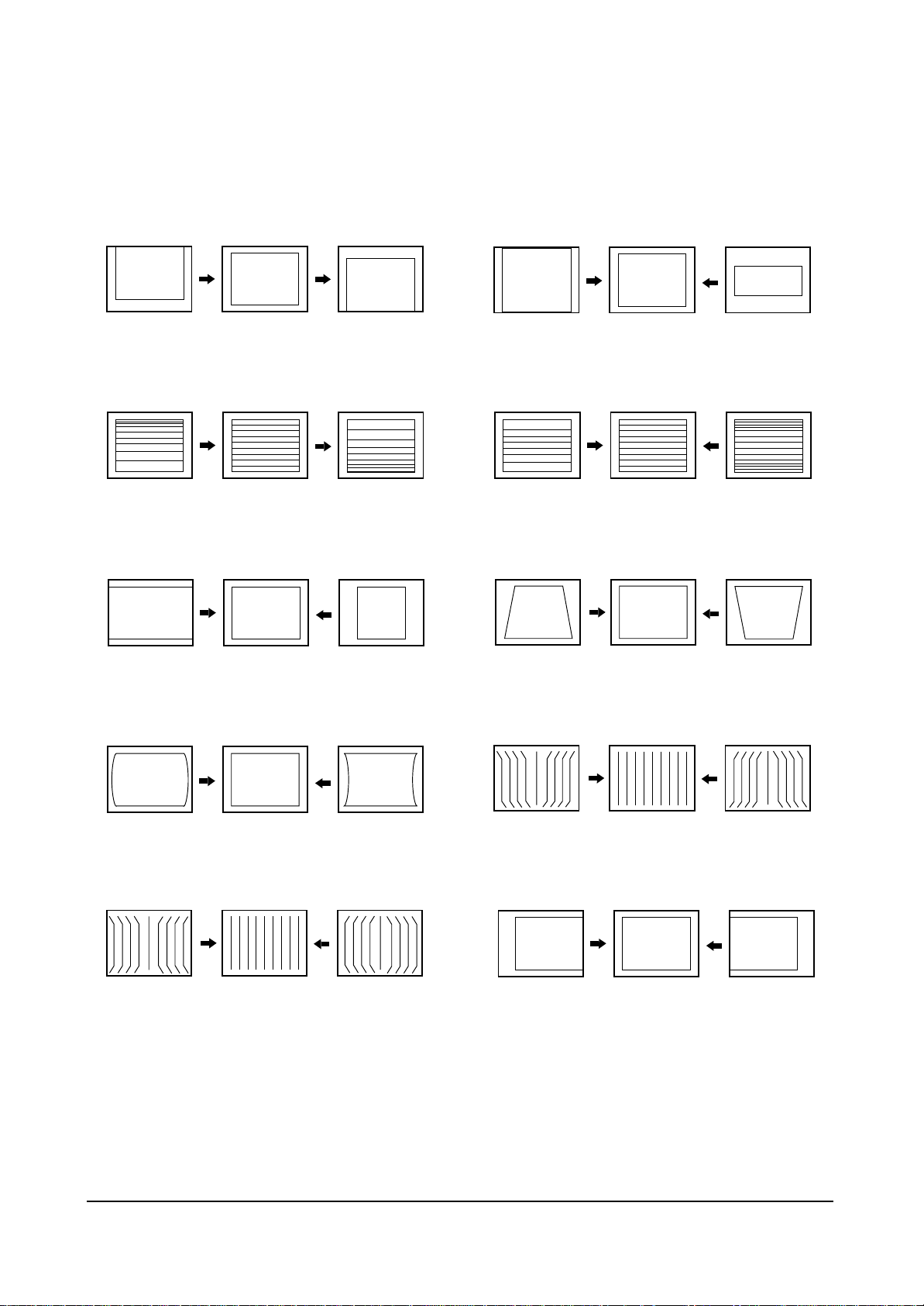
4-5-2(D) SCREEN CHANGE (I2C BUS GEOMETRIC ADJUSTMENT)
1 V Shift
V Slope
2
3 H EW
6 V Amp
V SC
7
8
H Trapizium
4 H Parabola
5 H Corner
9
10
H Shift
H Symmetry
Alignment and Adjustments
Samsung Electronics 4-7
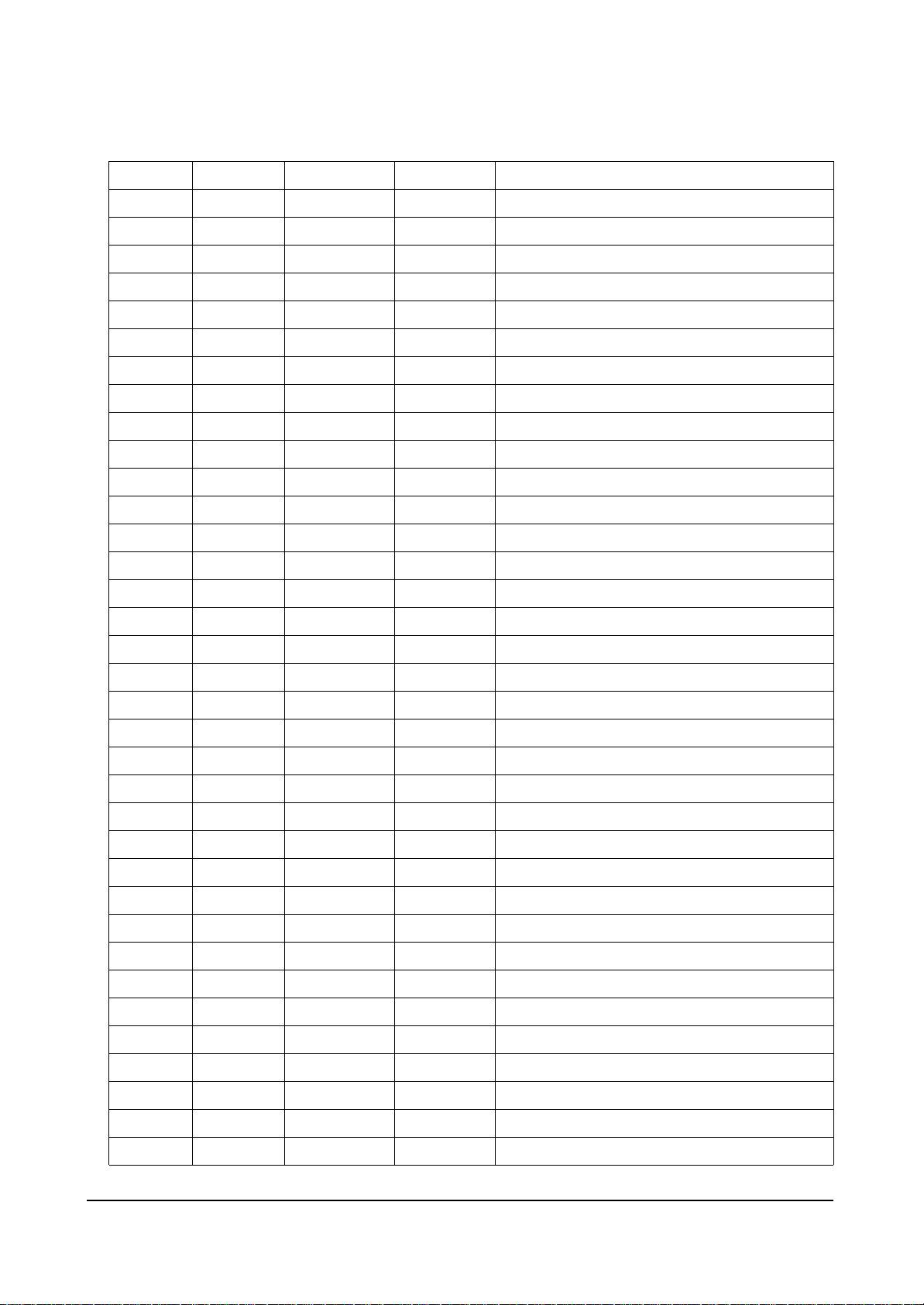
PIN NO
1
2
3
4
5
6
7
8
9
10
11
12
13
14
15
16
17
18
19
20
21
22
23
24
25
26
27
28
29
30
31
32
SYMBOL
P1.3/T1
P1.6/SCL
P1.7/SDA
P2.0/TPMW
P3.0/ADC0
P3.1/ADC1
P3.2/ADC2
P3.3/ADC3
VSSC/P
P0.5
P0.6
VSSA
SECPLL
VP2
DECDIG
PH2LF
PH1LF
GND3
DECBG
EWD
VDRB
VDRA
IFIN1
IFIN2
IREF
VSC
AGCOUT
SIFIN1/DVBIN1
SIFIN2/DVBIN2
GND2
SIFAGC/DVBAGCR
REFO/AMOUT/REFIN
PIN FUNCTION
port 1.3 or Counter/Timer 1 input
port 1.6 or IIC-bus clock line
port 1.7 or IIC-bus data line
port 2.0 or Tuning PWM output
port 3.0 or ADC0 input
port 3.1 or ADC1 input
port 3.2 or ADC2 input
port 3.3 or ADC3 input
digital ground for m-Controller core and periphery
port 0.5(8mA current sinking capability for direct drive of LEDs)
port 0.6(8mA current sinking capability for direct drive of LEDs)
digital ground of TV-processor
SECAM PLL decoupling
2nd supply voltage TV-processor(+8V)
supply voltage decoupling of digital circuit of TV-processor
phase-2 filter
phase-1 filter
ground 3 for TV-processor
bandgap decoupling
East-West drive output
vertical drive B output
vertical drive A output
IF input 1
IF input 2
reference current input
vertical sawtooth capacitor
tuner AGC output
SIF input 1 / DVB input 1
SIF input 2 / DVB input 2
ground 2 for TV processor
narrow band PLL filter
Automatic Volume Leveling/subcarr reference output/sound IF
input/external reference signal input for I signal mixer for DVB
operation
4-6
PIN ASSIGNMENT SPECIFICATION
CHECK VOLTAGE
S-By P-On
Alignment and Adjustments
4-8 Samsung Electronics
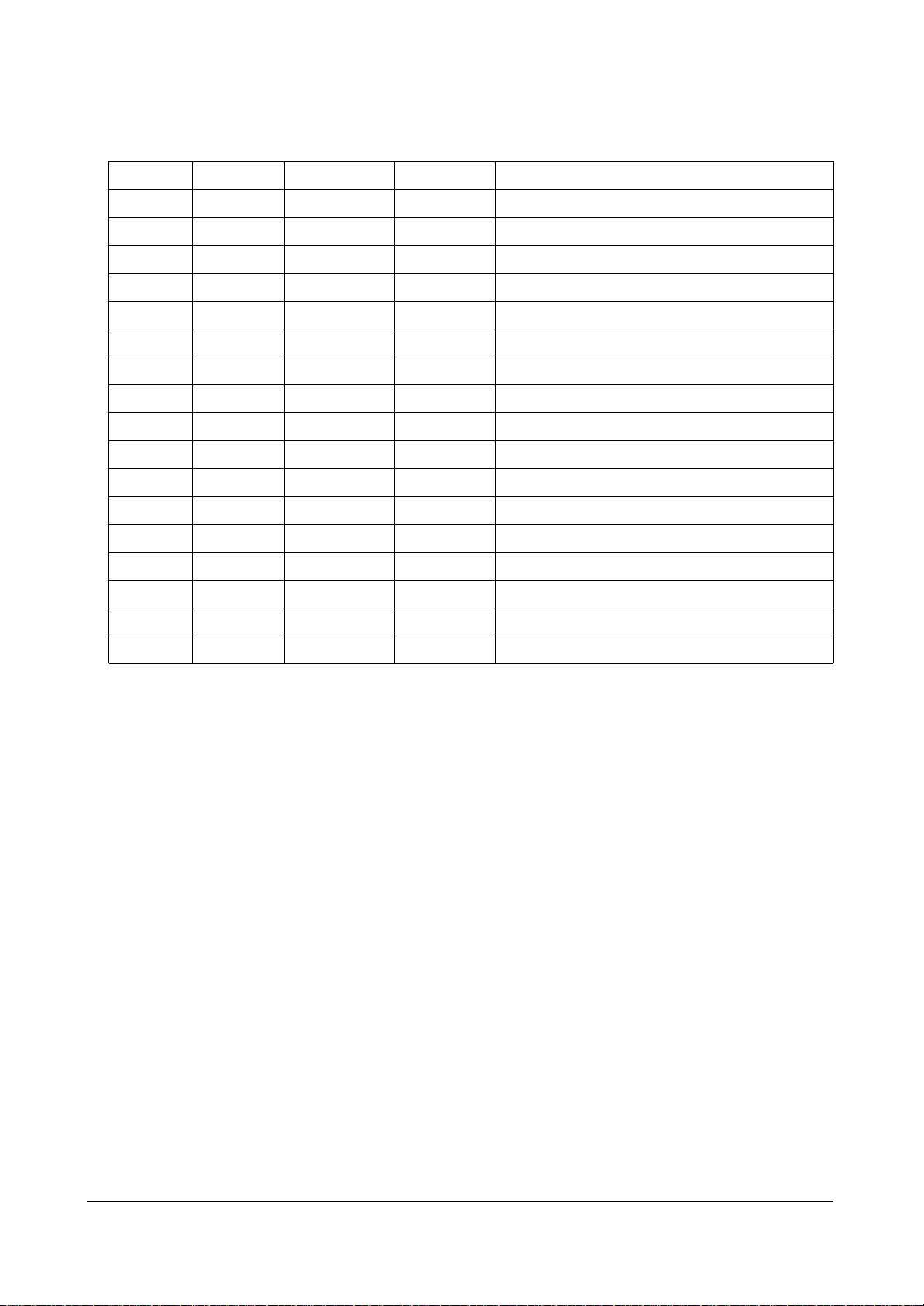
PIN NO
33
34
35
36
37
38
39
40
41
42
43
44
45
46
47
48
49
50
51
52
53
54
55
56
57
58
59
60
61
62
63
64
SYMBOL
HOUT
FBISO
QSSO/AMOUT
EHTO
PLLIF
IFVO/SVO/DVBO
VP1
CVBS1
GND
CVBS/Y
C
SVM
INSSW2
R2/VIN
G2/YIN
B2/UIN
BCLIN
BLKIN
RO
GO
BO
VDDA
VPE
VDDC
OSCGND
XTLIN
XTLOUT
RESET
VDDP
P1.0/INT1
P1.1/T0
P1.2/INTO
PIN FUNCTION
horizontal output
flyback input/sandcastle output
QSS intercarrier output/AM output in stereo applications or
deemphasis(front-end audio out)/AM output in mono applications
EHT/overvoltage protection input
IF-PLL loop filter
AGC sound IF/inter-external AGC for DVB applications
main supply voltage TV processor
internal CVBS input
ground for TV processor
CVBS3/Y input
chroma input
scan velocity modulation output
2nd RGB/YUV insertion input
2nd R input/V(R-Y) input PR input
2nd G input/Y input
2nd B input/U(B-Y) input PB input
beam current limiter input
black current input/V-guard input
Red output
Green output
Blue output
analog supply of Teletext decoder and digital supply of TVprocessor(3.3 V)
OTP Progamming Voltage
digital supply to core(3.3 V)
oscillator ground supply
crystal oscillator input
crystal oscillator output
reset
digital supply to peryipher(+3.3 V)
port 1.0 or external interrupt 1 input
port 1.1 or Counter/Timer 0 input
port 1.2 or external interrupt 0 input
CHECK VOLTAGE
S-By P-On
Samsung Electronics
Troubleshooting
5-1
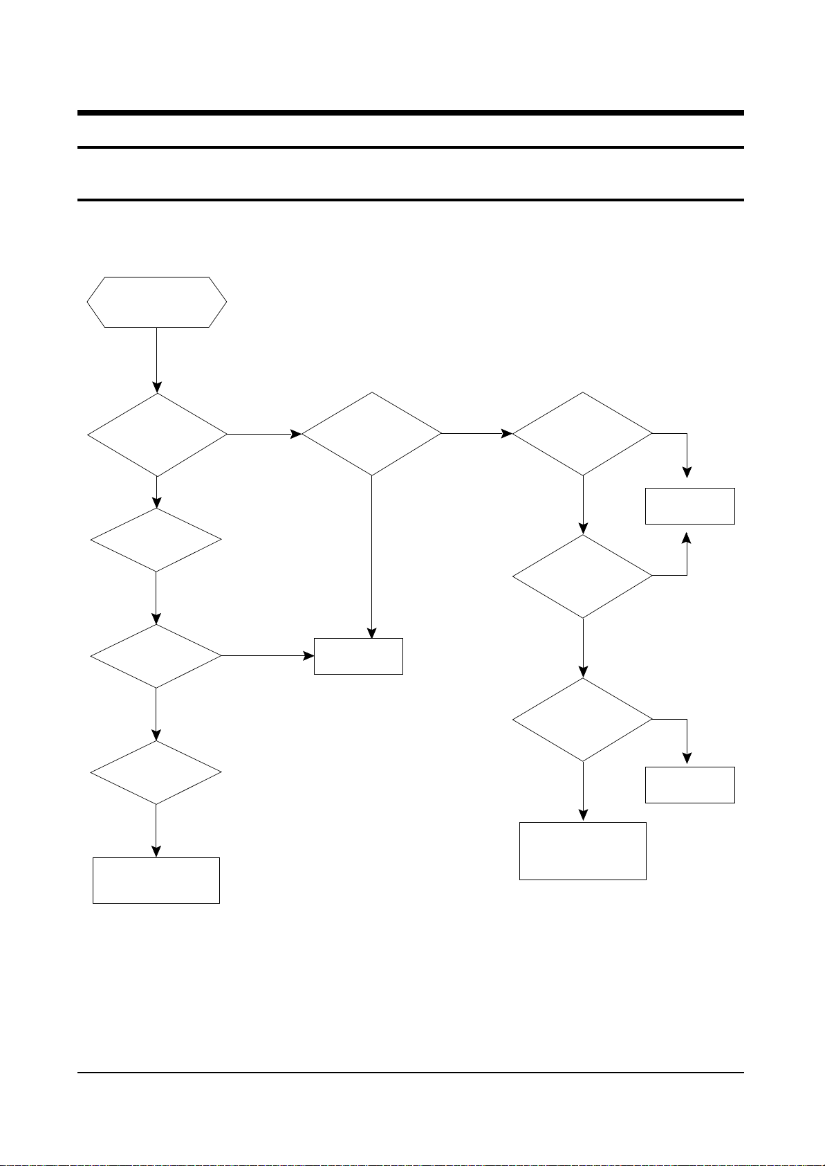
5. Troubleshooting
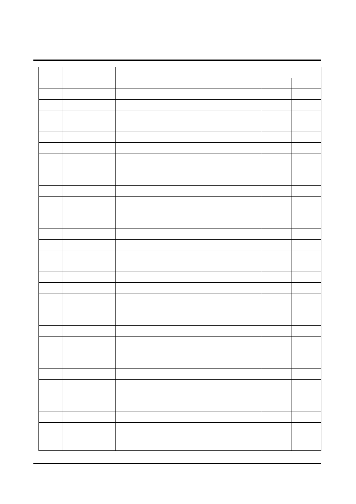
5-1 No Power
Counect
the Power code
Check
the
Power LED
LED Off
Check the
Voltage of IC102 #8
Abnormal
Check the
B+ 11.5V LIne
Abnormal
Check the
Micro fuse FD802S
LED On
Normal
Check the
IC201S, B+
#14, #39, #51, #54
Abnormal
Check/Replace
IC802
Normal
Check the
X-tal,SDA,SCL port
of IC201S
Normal
Check the
(33)Pin (H-Drive)
of IC201S
Normal
Check the
130V- A Line
Normal
Abnormal
Replace
IC201 S
Abnormal
Abnormal
Check the
FBT,D808
Abnormal
Check the
IC801S, D801S, FP801S
Check / Replace
Q401
5-2 Samsung Electronics
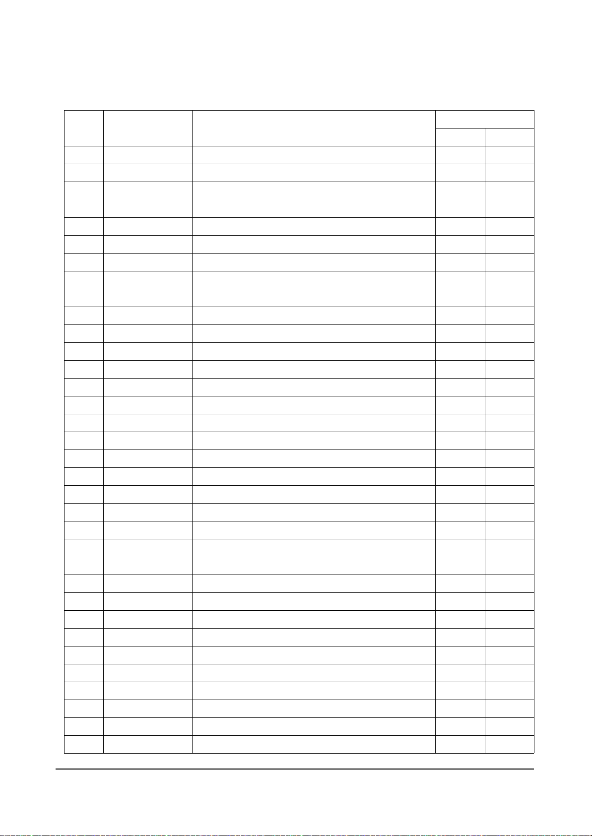
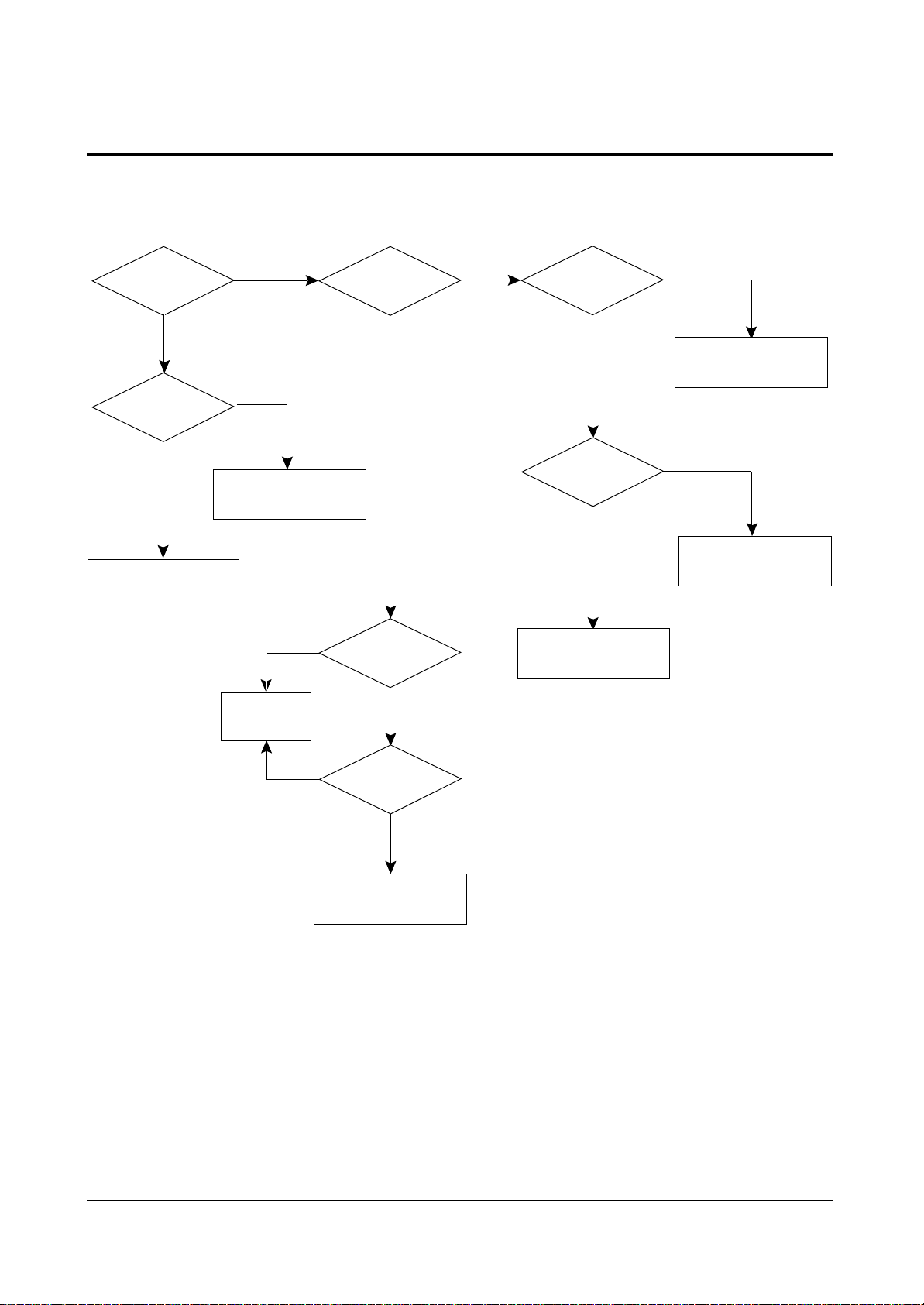
5-2 No Video (Sound OK)
Troubleshooting
Check RK,GK,BK
Signal
Nornal
Check the
Voltage of heater
Nornal
Check
CRT and FBT
Abnormal
Abnormal
Check/Replace
R418,R513, D503
Abnormal
Check/Replace
IC201S
Check R,G,B
Signal into CRT
PCB
Abnormal
Check IC201S
Pin 51, 52, 53
(R.G.B)
Nornal
Nornal
Check IC501
B+(180V-B)
Abnormal
Check the
resistance of R512
Nornal
Check/Replace
D405, FBT
Nornal
Re-Adjust
Screen Voltage
Abnormal
Replace
R512
Abnormal
Check IC201S
Pin 49(V-GUARD)
Pin50(IK)
Nornal
Check
CRT and FBT
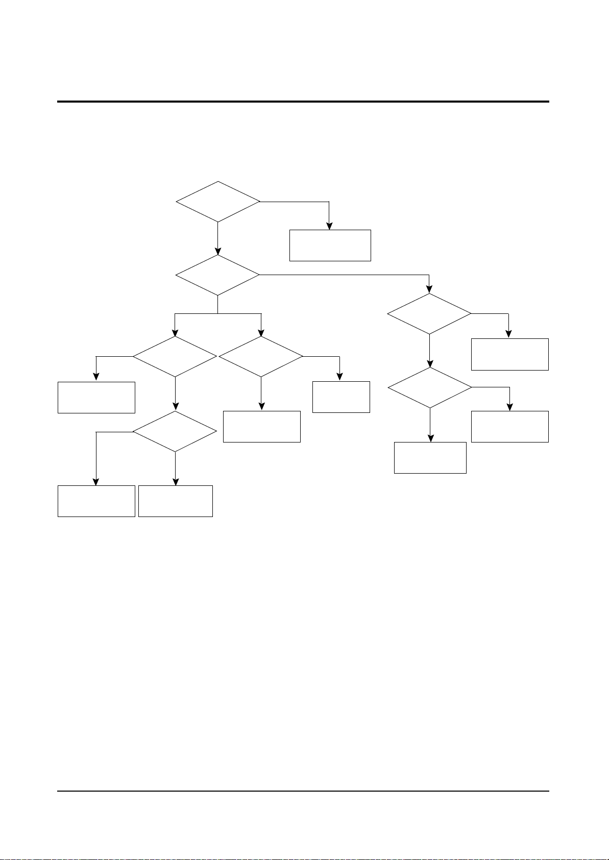
5-3 No Sound (Video OK)
Troubleshooting
Samsung Electronics 5-3
Check the
TUNER
Abnormal
Abnormal
* STEREO
Check IC602
Pin47(SIF)
Normal
Check IC602
B+
Normal
Check the signal
Output from CN601
CN602
Abnormal
Check IC601
Pin8,9
Abnormal
* MONO
Check IC201S
Pin32(SIF)
Normal
Check/Replace
IC201S
Normal
Check
Speaker and Wire
Abnormal
Check
IC101,TUNER
Normal
Abnormal
Check FD801S
Normal
Check IC601
B+
D805
See
No Power
Normal
Replace
IC601
Abnormal
Replace
FD801S,D805
Check B+ Line
5V-B, 8V-B
Check/Replace
IC602
5-4 Samsung Electronics
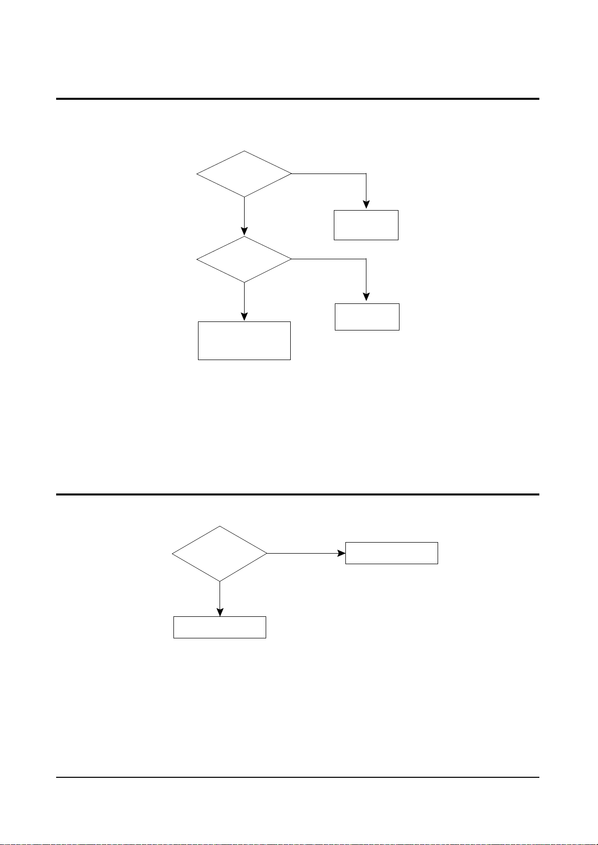
Troubleshooting
5-4 Horizontal Lines Appear or Screen
5-5 No TTX
Check IC301 B+
16V-C,-13.5V-C
Normal
Check IC201S
Pin 21,22
(VDN,VDP)
Normal
Check / Replace
IC301
Abnormal
Check
R412, R416
DD401, D404
Abnormal
Check
IC201S
Check IC201S
Normal
See No Video (Sound ok)
Abnormal
Check/Replace
IC201S
 Loading...