

SAMSUNG CW28C33NS8XXEC(KS3A_50Hz), CW28C75V Service Manual Alignment & Adjustment

Alignment and Adjustments
Samsung Electronics 4-1
4. Alignment and Adjustments
4-1 General Alignment Instructions
1. Usually, a color TV-VCR needs only slight
touch-up adjustment upon installation. Check
the basic characteristics such as height,
horizontal and vertical sync and focus.
2. Observe the picture for good black and white
details. There should be objectionable color
shading; if color shading is present,
demagnetize, perform purity and convergence
adjustments described below.
3. Use the specified test equipment or its
equivalent.
4. Correct impedance matching is essential.
5. Avoid overload. Excessive signal from a
sweep generator might overload the front-end
of the TV. When inserting signal markers, do
not allow the marker generator to distort test
results.
6. Connect the TV only to an AC power source
with voltage and frequency as specified on the
backcover nameplate.
7. Do not attempt to connect or disconnect any
wires while the TV is turned on. Make sure
that the power cord is disconnected before
replacing any parts.
8. To protect against shock hazard, use an
isolation transformer.
4-2 Automatic Degaussing
A degaussing coil is mounted around the
picture tube, so that external degaussing after
moving the TV should be unnecessary. But
the receiver must be properly degaussed upon
installation.
The degaussing coil operates for about 1
second after the power is switched ON. If the
set is moved or turned in a different direction,
the power should be OFF for at least 10
minutes.
If the chassis or parts of the cabinet become
magnetized, poor color purity will result. If
this happens, use an external degaussing coil.
Slowly move the degaussing coil around the
faceplate of the picture tube and the sides and
front of the receiver. Slowly withdraw the coil
to a distance of about 6 feet before turning
power OFF.
If color shading persists, perform the
following Color purity and Convergence
adjustments.
4-3 High voltage Check
CAUTION : There is no high voltage adjustment
on this chassis. The B+ power supply should be
+135 volts (with full color- bar input and normal
picture level).
1. Connect a digital voltmeter to the second
anode of the picture tube.
2. Turn on the TV. Set the Brightness and
Contrast controls to minimum (zero beam
current).
3. Adjust the Brightness and contrast controls to
both extremes. Ensure that the high voltage
does not exceed 32 KV under any conditions.
Alignment and Adjustments
4-2 Samsung Electronics
4-5 SCREEN Adjustment
1. Input Toshiba Pattern
2. Enter “Service Mode”.(Refer to “Service Mode”)
3. Select “G2-Adjust”.
4. Set the values as example(Refer to page4-24).
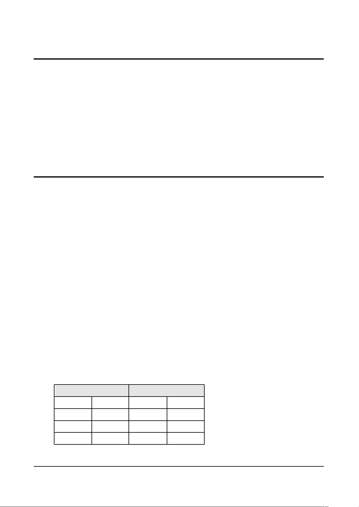
4-4 Dynamic Focus Adjustment
1. A dynamic focus adjustment should be done
after replacing the CRT PCB, FBT or CRT.
2. Input a crosshatch pattern.
3. Enter “ STANDARD “ in video mode.
4. Turn the Dynamic focus VR fully clockwise
(maximum).( ❶ )
5. Turn the Static focus VR fully
counterclockwise (maximum).( ❷ )
6. Slowly turn the static focus VR
counterclockwise. Adjust until the
vertical line in the middle of the screen
has maximum clarity.( ❶ )
7. Slowly turn the dynamic focus VR (clockwise)
and adjust the 3rd horizontal line for
maximum clarity.( ❷ )
8. Repeat 4-7, if necessary.
❷
❶
❷
❶
ex) IBRM = 220
WDRV = 35
CDL = 220
COLR G B = 150 150 150
STATIC FOCUS VR
H
DYNAMIC FOCUS VR
V
SCREEN
<FBT FOCUS PACK>

Alignment and Adjustments
Samsung Electronics 4-3
When you do not have Toshiba Pattern, follow this method.
1. Set the TV on the condition that AV mode no signal(black)
2. Enter the “Menu” and set the mode to blue screen off.
3. Enter the “Service Mode”.
4. Select “ G2-Adjust”.
5. Set the values as example(Refer to page4-24).
ex) IBRM = 220
WDRV = 35
CDL = 220
COLR G B = 150 150 150
6. Turn the SCREEN VR until the value of “ MRCR G B” is about 120. Do not mind that
the “OSD” Color is red.
■ After completing G2-Adjust, follow this procedure.
① Enter the “Video Adjust 1”.
➁ Choose any item in menu. (ex. Select “Red Cutoff”)
➂ Change the value of item you select, and recover the value.
For example, when the value of “Red Cutoff” is 127, change the value to 128 and restore
the value to 127.
If you do not follow this procedure, the picture may be abnormal.
For example, when the TV set is on, the picture becames brighter gradually.
Note 1.
5. Turn the SCREEN VR until “MRCR G B” and “MRWDG” are green and those value are about 100.
(The incorrect SCREEN Voltage may result that “MRCR G B” and “MRWDG” should be red)
Alignment and Adjustments
4-4 Samsung Electronics
4-6 E2PROM (IC902) Replacement
1. When IC902 is replaced, all adjustment data revert to the initial values.
So, all adjustment values when servicing should be readjusted.
2. After IC902 is replaced, connect the AC power supply cord.
3. Turn the power switch ON.
4. In stand-by, warm up the TV for at least 10 seconds.
5. Power on the TV.
4-7 White Balance Adjustment
■ Equipment : Color-Analyzer (CA-100)
■ Input Signal : Pattern signal (Toshiba pattern)
1. Select STANDARD from the menu.
2. Input an 100% White pattern.
3. Enter the “Service Mode”. (Refer to “4-8 Service Mode”)
4. Warm up the TV set at least for 30 minutes.
5. Input a Toshiba pattern signal.
6. Enter the “Video Adjust1”.
- Adjust “Sub Contrast” so that Y (luminance) becomes 40 ft ± 3.
- Use “Red Drive” and “ Blue Drive” to adjust High-Light (x : 290, y : 300)
- Adjust “Sub Bright” so that Y (luminance) becomes 1.3ft ± 0.3.
- Use “Red Cutoff” and “Blue Cutoff” to adjust Low-Light (x : 290, y : 300).
7. Adjust CA-100 so that the final adjustment value can be fixed.
8. Use the Channel Up/Down (▲/▼) buttons to move the cursor on the adjustment modes.
9. Use the Volume +/- buttons to change the adjustment value.
■ SMPS Controller differentiol List
LOC.
DZ808
C811
C828
1265RD
1265RB
SPEC
MTZ8.28
47NF
221.50V
SPEC
MTZ8.28
47NF
221.50V
LOC.
DZ808
C811
C828
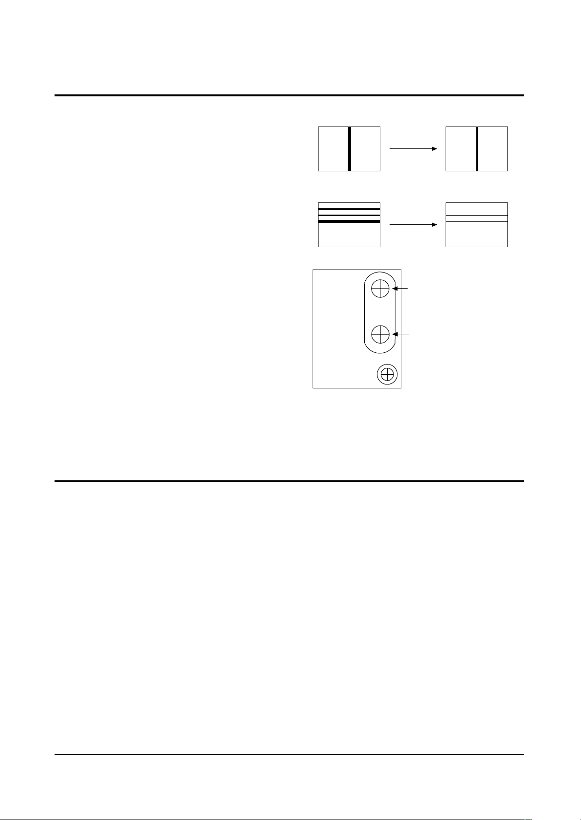
■ Background : It is occurred to service confusion
■ Cause : CRT Socket PCB change as CRT changing from Double Focus to Single Focus
■ How to service
Code : It is different to CRT Socket Code per focus type
Case :
1. Using CRT Socket PCB for Single Focus at CRT for Double Focus
(1) Change the CRT Socket in PCB(Single → Double).
(2) Cut the red-colored focus wire of FBT in set.
(3) Connect the wires at Focus terminal like picture #1 for short circuit using red-colored focos
wire of FTB.
2. Using CRT Socket PCB for Double Focus at CRT for Single Focus
(1) Change the CRT Socket in PCB(Double → Single).
(2) Cut the red-colored focus wire of FBT in set like picture #2.
❈ You mus tape the isolation parts for safety.
Alignment and Adjustments
Samsung Electronics 4-5
KS3A 29” Flat 50Hz, CRT Change(Double Focus →→Single Focu)
Note 2.
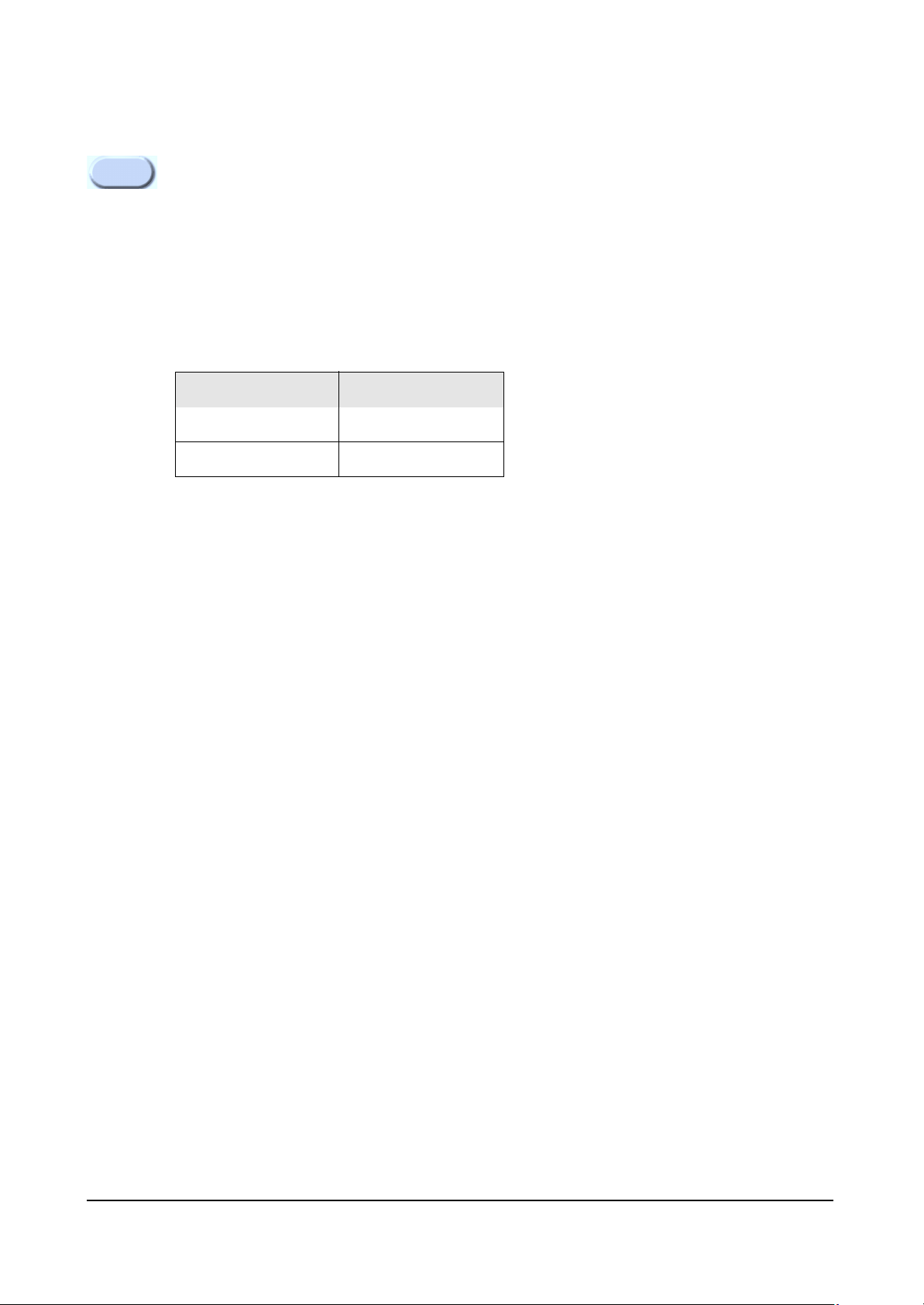
CRT Socket
For Double Focus
For Single Focus
Code No
3704-001032
3704-000114
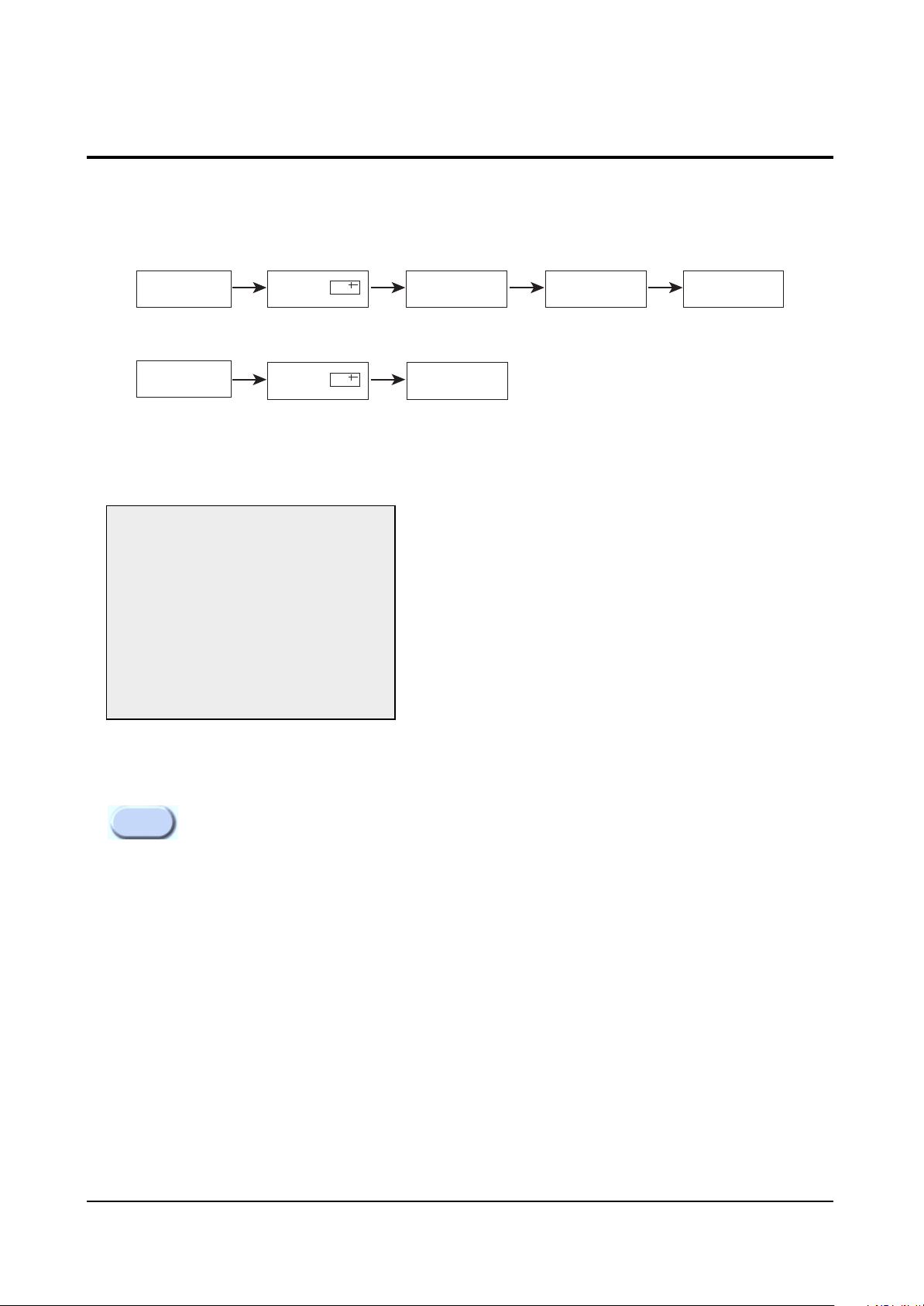
PICTURE OFF PICTURE ON
PICTURE ON
DISPLAY
()
DISPLAY
()
MENU
FACTORY
MUTE
Alignment and Adjustments
4-6 Samsung Electronics
4-8 Factory Adjustment
1. To enter the “Service Mode”, Press the remote-control keys in this sequence :
- If you do not have Factory remote-control
- If you have Factory remote-control
2. After the Service Mode is entered, the initial screen is as shown in the figure below.
3. Use the Channel Up/Down buttons to move the cursor in the adjustment parameters.
- When CRT, CRT PCB, FBT, E
2
PROM (sometimes MICOM) is replaced, the adjustment values
should be controlled.
- After the Service adjustment is completed, Do not select “Reset” in the service mode menu.
(After above procedure is done, power is on initially and the “Plug and Play” will be operated.)
4-8-1 Service Mode
*
These hexa digits are check sum value which
depends on the MICOM.
If check sum value is changed, the value of
E
2
PROM Data newly initialed.
Note 3.
Service
Deflection
Video Adjust 1
Video Adjust 2
Video Adjust 3
Option(81h 0Ch)
Reset
G2-Adjust
Others
*
Alignment and Adjustments
Samsung Electronics 4-7
4-8-2 Memory Data
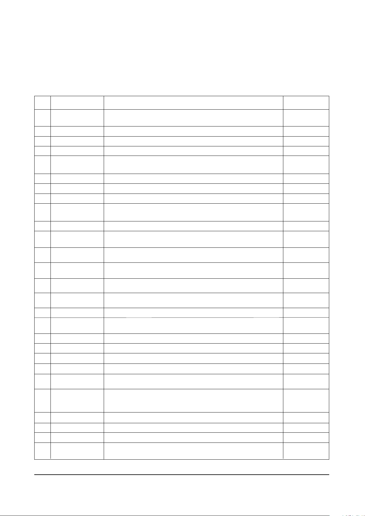
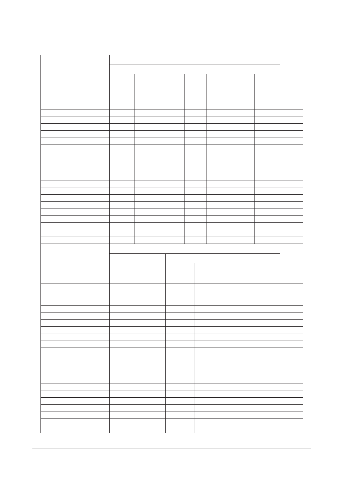
4-8-2(A) DEFLECTION (GEOMETRIC ADJUSTMENT VALUE)
No.
1
2
3
4
5
6
7
8
9
10
11
12
13
14
15
16
17
18
19
20
21
22
23
24
25
26
27
OSD
V Amp
V Shift
V Slope
V SC
H EW
H Trapizium
H Parabola
H Symmetry
H Corner
H Shift
Zoom 4:3 Para
4:3~16:9 Para
Wide-4:3 Para
Wide-Zoom Para
Wide-Zoom2 Para
Zoom1 Amp
Zoom2 Amp
TTX Position
D-TTX Posi
RGB Shift
PIP Contrast
PIP Tint
PIP V.Move(VSPDEL)
PIP PAL V.Pos
PIP NTSC V.Pos
PIP H.Pos
PIP BLKLG
Function
Adjusts Vertical picture size. Adjust 4:4 upper and below picture size in
lion head pattern at factory.
Adjusts Vertical picture position
Adjusts Vertical Slope Correction
Adjusts Vertical s-correction
Horizontal east west width. Adjust 5:5 left and right picture size in lion
head pattern at factory.
Adjusts horizontal Trapezium.
Adjusts Horizontal Parabola.
Adjusts Picture upper and below horizontal Symmetry.
Adjusts Picture upper and below Horizontal Corner.After adjust the
Parabola, adjust H corner vertical Line upper and below has nonlinear.
Adjusts Horizontal Position.
Corrects the vertical linearity in Zoom mode of P-SIZE.
The data depends on CRT (see data above)
Corrects the vertical linearity in 16:9 mode of P-SIZE.
The data differs according to CRT (see data above).
Corrects the vertical linearity in wide mode of P-SIZE.
The data differs according to CRT (see data above).
Corrects the vertical linearity in wide mode of P-SIZE.
The data differs according to CRT (see data above).
Corrects the vertical linearity in wide mode of P-SIZE.
The data differs according to CRT (see data above).
Adjusts vertical amplitude in zoom1
Adjusts vertical amplitude in zoom2. Zoom2 mode is a manual zoom
mode
Sets TTX Position.
Double -TTX position.
Adjusts RGB input signal Horizontal position
Adjusts PIP contrast.
Adjusts PIP Tint. It is a function to control color phase of NTSC signal in
PIP
PIP vertical sync pulse delay. When changing data, PIP jitters at two
points.
In this case, the PIP VSPDEL is set to the center between two points.
Adjusts Vertical position of PIP in PAL system.
Adjusts Vertical position of PIP in NTSC system.
Adjusts Horizontal Position of the PIP.
PIP blanking level green(PIP low light white balance).
It is used to control low light white balance in PIP
Remark
Adjust
Adjust
Adjust
Fix
Adjust
Adjust
Adjust
Fix
Adjust
Adjust
Fix
Adjust
Adjust
Adjust
Fix
Fix
Fix
Fix
Fix
Fix
Fix
Fix
Fix
Fix
Fix
Fix
Fix
Alignment and Adjustments
4-8 Samsung Electronics
V Amp
V Shift
V Slope
V SC
H EW
H Trapizium
H Parabola
H Corner L
H Corner L
H Shift
BOW
Amgle
H Corner U6
H Corner L6
V Max
Zoom1 Amp
Zoom2 Amp
Zoom Trap
H-QEW
Zoom 4:3 Para
4:3~16:9 Para
V Amp
V Shift
V Slope
V SC
H EW
H Trapizium
H Parabola
H Corner L
H Corner L
H Shift
BOW
Amgle
H Corner U6
H Corner L6
V Max
Zoom1 Amp
Zoom2 Amp
Zoom Trap
H-QEW
Zoom 4:3 Para
4:3~16:9 Para
RANGEOSD
0 ~ 255
0 ~ 255
0 ~ 255
0 ~ 255
0 ~ 255
0 ~ 255
0 ~ 255
0 ~ 255
0 ~ 255
0 ~ 255
0 ~ 255
0 ~ 255
0 ~ 255
0 ~ 255
0 ~ 255
0 ~ 255
0 ~ 255
0 ~ 255
0 ~ 255
0 ~ 255
0 ~ 255
RANGEOSD
0 ~ 255
0 ~ 255
0 ~ 255
0 ~ 255
0 ~ 255
0 ~ 255
0 ~ 255
0 ~ 255
0 ~ 255
0 ~ 255
0 ~ 255
0 ~ 255
0 ~ 255
0 ~ 255
0 ~ 255
0 ~ 255
0 ~ 255
0 ~ 255
0 ~ 255
0 ~ 255
0 ~ 255
INITIAL DATA
SIM-806HEW
32W8VH
Philips
Invar Flat
80
104
125
117
125
85
65
45
88
185
132
129
176
176
128
150
202
128
-
-
-
32W8VH
Thomson
Invar Flat
92
111
130
225
215
113
96
121
122
170
130
140
76
78
128
143
173
128
128
-
-
28C7VH
Thomson
Invar 2.0R
85
108
130
200
205
91
65
118
136
174
123
129
140
136
213
180
202
128
-
-
-
28C7H
Thomson
AK 2.0R
129
110
130
200
187
114
91
118
136
180
123
129
133
129
213
180
202
128
128
-
-
28C7H
Philips
Invar 2.0R
129
110
130
200
187
114
91
118
136
180
123
129
133
129
213
180
202
128
-
-
-
INITIAL DATA
SIM-806HEW SIM-806HMA/806HEA/806HC
29A8VH
SED
Invar Flat
128
153
133
210
109
108
112
125
118
183
123
129
126
136
200
195
202
128
128
-
-
28W8VH
SED
Invar Flat
104
109
107
175
161
124
110
108
111
188
127
127
138
140
127
148
178
128
128
-
-
29A7HP
SED
V-Before
148
149
134
206
183
110
94
130
133
195
127
128
131
130
200
187
128
128
-
5
29A7HP
SED
V-After
106
141
134
206
195
105
79
130
143
195
127
128
131
130
200
179
128
128
-
5
28W6
Thomson
AK 2.0R
84
117
130
200
172
108
82
118
136
177
121
132
135
126
128
146
171
128
128
34A7HP
Toshiba
V-Before
133
151
134
189
179
95
81
145
150
186
127
128
127
134
200
198
131
128
-
5
-
-
32W6V
Thomson
Invar 2.0R
80
116
115
150
232
107
92
73
92
185
123
129
159
158
128
150
190
128
-
-
-
34A7HP
Toshiba
V-After
124
125
125
210
215
92
71
134
159
189
127
128
133
126
200
189
131
128
-
5
Remarks
GEOM
GEOM
FIX
FIX
GEOM
GEOM
GEOM
FIX
FIX
GEOM
GEOM
GEOM
GEOM
GEOM
FIX
FIX
FIX
FIX
-
-
-
Remarks
GEOM
GEOM
FIX
FIX
GEOM
GEOM
GEOM
FIX
FIX
GEOM
GEOM
GEOM
GEOM
GEOM
FIX
FIX
FIX
FIX
-
-
-
Alignment and Adjustments
Samsung Electronics 4-9
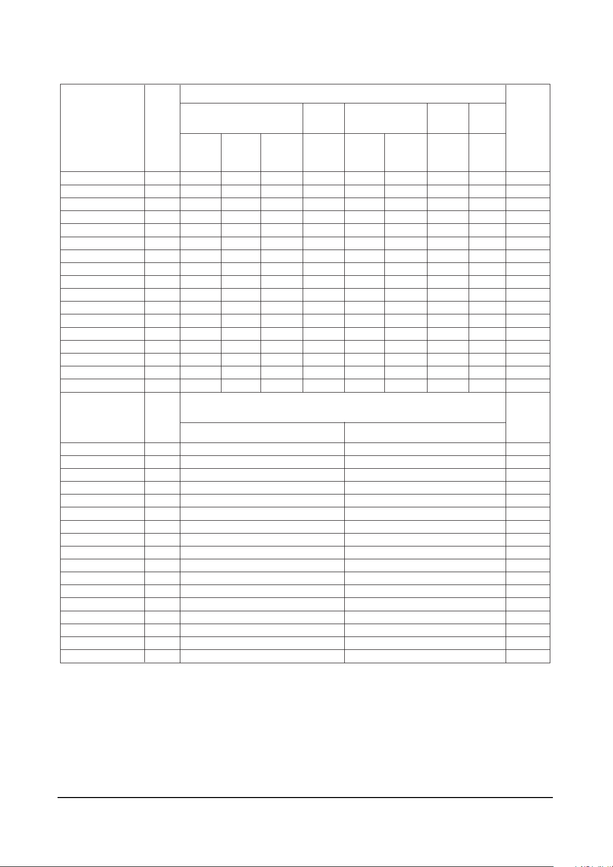
INITIAL DATA
V Amp
V Shift
V Slope
V SC
H EW
H Trapizium
H Parabola
H Symmetry
H Corner
H Shift
PIP Contrast
PIP Tint
PIP V.Move(VSPDEL)
PIP PAL V.Pos
PIP NTSC V.Pos
PIP H.Pos
PIP BLKLG
V Amp
V Shift
V Slope
V SC
H EW
H Trapizium
H Parabola
H Symmetry
H Corner
H Shift
PIP Contrast
PIP Tint
PIP V.Move(VSPDEL)
PIP PAL V.Pos
PIP NTSC V.Pos
PIP H.Pos
PIP BLKLG
SIM-812MA3
RANGEOSD
29"
Flat/
DVD
-30/55
-7
-3
-17
30
-47
-7
10/13
23
13
8
0
0
26
23
30
6
CIS
29"
Flat
-30
-7
-3
-17
30
-47
-7
13
23
13
8
0
17
26
23
30
6
CIS 29"
Flat SKD
CKD
-30
-7
-3
-17
30
-47
-7
13
23
13
8
0
0
26
23
30
6
SIM-
812MAD
29"
Flat
-45
-2
-3
-17
30
-34
10
10
-10
27
10
0
17
23
20
27
3
SIM-806MA3
34"
Flat
7
29"
Flat
-55
-22
-7
-15
-17
-8
-22
-47
-6
10
-8
-13
7
0
8
26
23
30
6
-7
-3
30
-7
10
23
13
8
0
17
26
23
30
6
SIM-
812EA1
29"
Flat
-55
-7
-3
-17
30
-47
-7
10
23
13
8
0
17
26
23
30
6
SIM-
806EI1
29"
Flat
-65
-7
-3
-15
30
-47
-7
10
23
13
10
0
17
25
25
30
7
Remarks
GEOM
GEOM
GEOM
FIX
GEOM
GEOM
GEOM
FIX
GEOM
GEOM
FIX
FIX
FIX
FIX
FIX
FIX
FIX
SIM-806EI3
RANGEOSD
Remarks
21" Flat 29" Normal
-51
-32
-4
-2
0
0
0
0
0
24
15
0
11
25
25
30
7
-23
-23
-8
0
42
-40
-60
13
70
10
15
0
8
25
25
47
7
GEOM
GEOM
GEOM
FIX
GEOM
GEOM
GEOM
FIX
GEOM
GEOM
FIX
FIX
FIX
FIX
FIX
FIX
FIX
 Loading...