

Samsung CSH9839, CSH7839, CSH780 Disassemble
5-1-1 Before making Disassembly
1. Disconnector signal cable and power cord
from the monitor.
2. With a pad beneath it, stand the monitor on its
front with the screen facing downward and
the base close to you.
3. Make sure nothing will damage the screen.
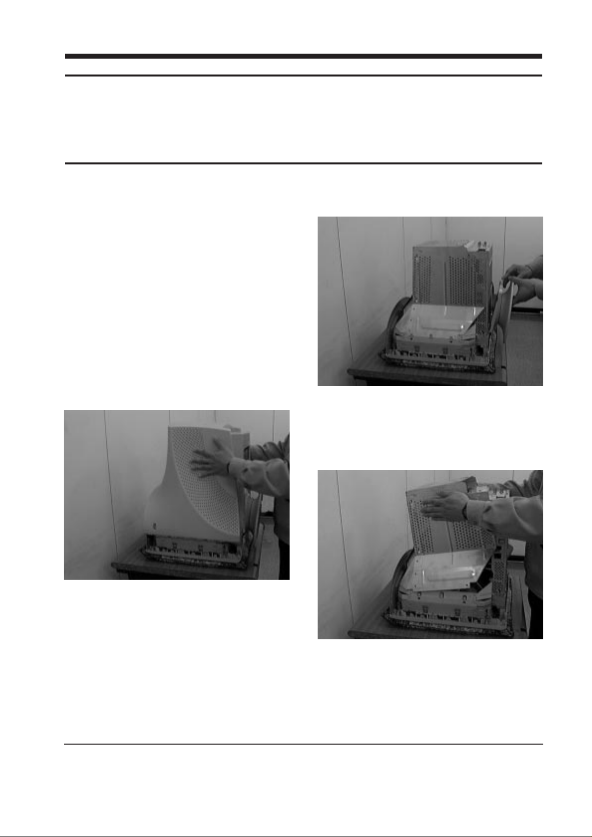
5-1-2 Cabinet Disassembly
1. To uncover the 2 uppermost screws. Press in
the end of each screw cap and pull it away
from the cabinet.
2. Remove the 4 screw on the Rear Cover and
pull it toward to remove it.
5-1-3 Removing the Stand
1. Pull the tab outward on the Chassis Bottom
and pull the Tilt and Swivel Base up to
remove it.
5-1-4 Removing the Top Shield
1. Remove the 4 screws on the Top Shield Cover
and remove the Shield.
CSH7839L/CSH9839L 5-1
5 Disassembly and Reassembly
This section of the service manual describes the disassembly and reassembly procedures for the
CSH7839L/CSH9839L monitors.
WARNING: This monitor contains electrostatically sensitive devices. Use caution when handling
these components.
5-1 Disassembly
Cautions:1. Disconnect the monitor from the power source before disassembly.
2. Follow these directions carefully; never use metal instruments to pry apart the cabinet.
Figure 5-1
Figure 5-2
Figure 5-3
5-1-5 Removing the Bottom Shield
1. Remove the 1 screw on the Bottom Shield
Cover.
2. Lift off the Bottom Shield.
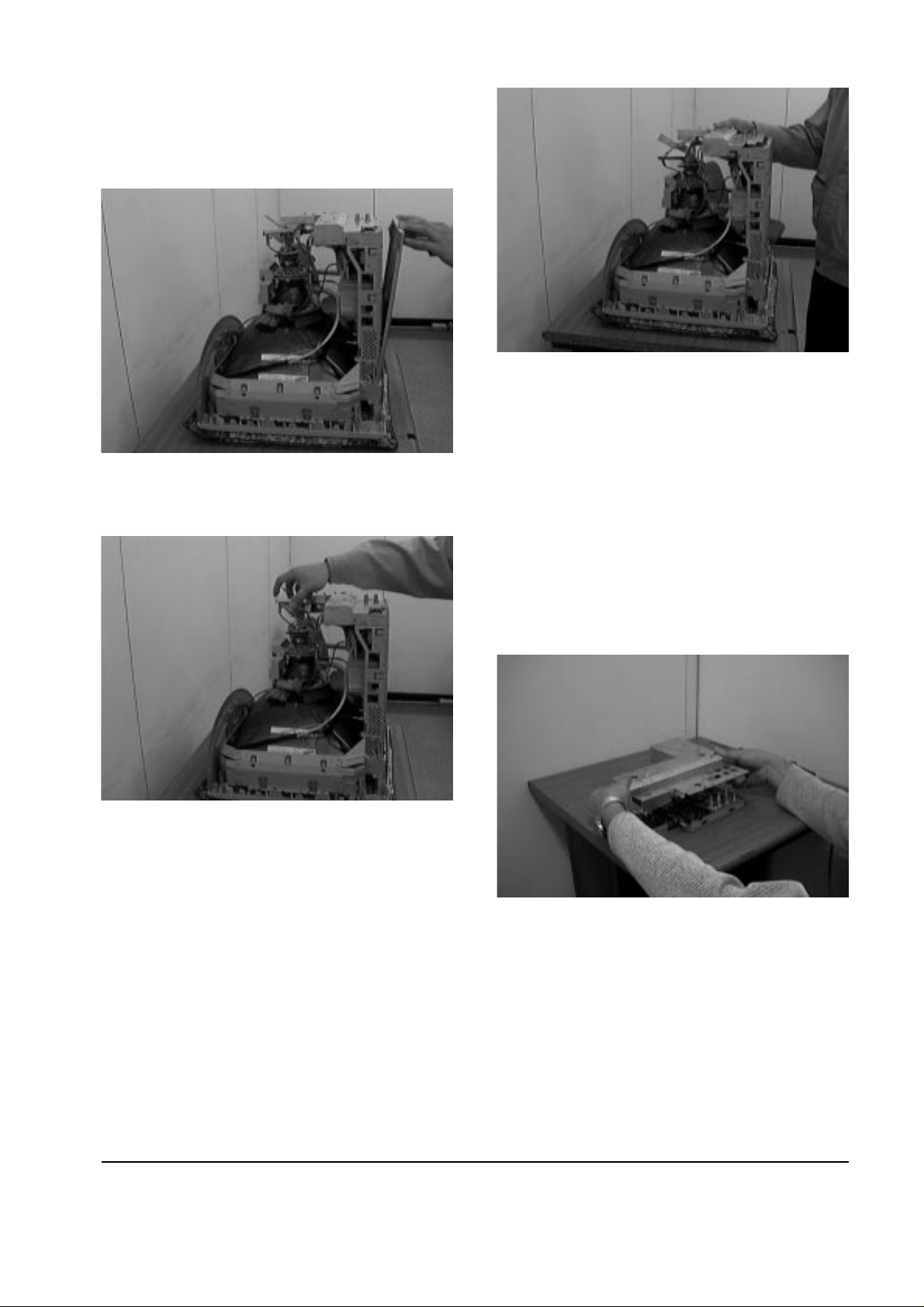
5-1-6 Removing the CRT Socket PCB
1. Disconnect connectors GT186 and GT188 on
the CRT PCB Assembly.
2. Disconnect the CRT Socket PCB Assembly.
5-1-7 Removing the Video PCB Assembly
1. Remove the 4 screws (both side and Rear part
of Main PCB Bracket) on the Video PCB.
2. Disconnect CN402, CN104, CN102, CN301 and
CN105 on the Video PCB Assembly.
3. Lift off the Video PCB Assembly.
5-1-8 Removing the Video PCB Assembly
Rear Shield and Video PCB
1. Remove the 9 screws on the PCB Assembly.
2. Using pinch-nosed pliers or long-nosed pliers,
pull both side taps of Video PCB Assembly.
3. Lift off the Video PCB Assembly Rear Shield.
4. Remove the 3 screws on the Video PCB
Bracket.
5. Lift out the Video PCB and pleat it on a flat,
level surface that is protected from static
electricity.
5-1-9 Removing the Main PCB Assembly
1. Remove both side screws (4 screws) on the
lower edge of the CRT Bracket.
2. Remove Chassis Ground Wire on the side of
the left.
3. Disconnect CN203, CN601, H_DY and Anode
Cap on the Main PCB Assembly.
5 Disassembly and Reassembly
5-2 CSH7839L/CSH9839L
Figure 5-5
Figure 5-6
Figure 5-4
Figure 5-7
 Loading...