

Page 1
Alignment and Adjustments
Samsung Electronics 2-1
2. Alignment and Adjustments
2-1 Adjustments
2-1-1 General Alignment Instructions
Usually, a color TV needs only slight touch-up adjustment upon installation. Check the basic
characteristics such as vertical size, horizontal size, and focus. Observe the picture and check for
good black and white details. There must be no objectionable color shading: If color shading is
present, demagnetize the receiver. If color shading persists, re-do purity and convergence adjustments.
Note :
1. This ‘4. Alignment and Adjustments’ applies to S61Achassis applications.
2. AC Power Supply: 160~300V or 100~240V, 50Hz
3. This service manual has been written on the basis of domestic remote-control model adopting S61A
chassis. Depending on sales location and product specifications, some of specifications herein may
be changed.
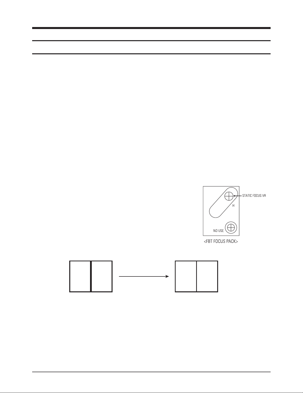
2-1-2 Focus Adjustment
S61A contains a dynamic focus circuit. When CRT PCB, FBT or CRT is replaced, be sure to adjust in the
following sequence:
Focus Adjustment
1. Input a crosshatch pattern.
2. Select “Standard” from the menu,
3. Turn the Static Focus VR clockwise to set it to its maximum.
4. Turn the Static Focus VR counterclockwise slowly for the clearest
center vertical line.
5. Turn the Dynamic Focus VR clockwise slowly for the clearest third line.
6. Check for the FOCUS of entire screen. If necessary,
re-do adjustments 3~5.
hGh
Page 2
Alignment and Adjustments
2-2 Samsung Electronics
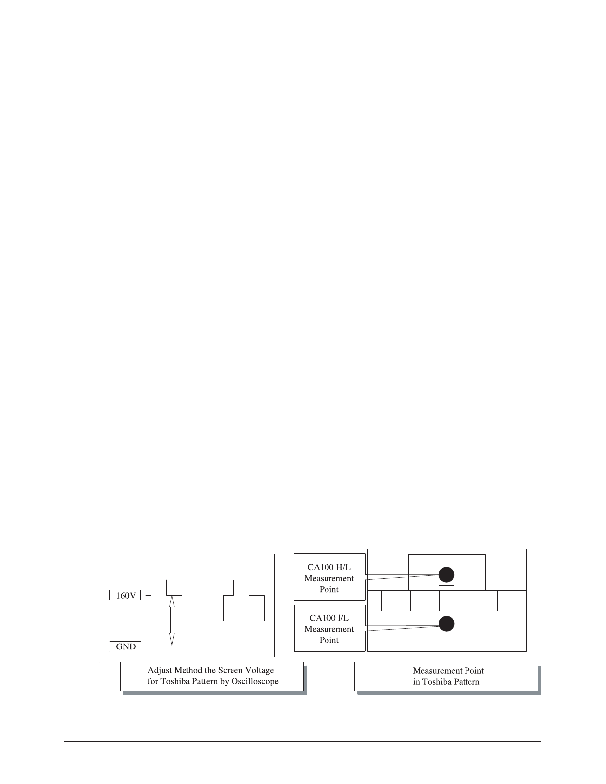
2-1-3 Screen Voltage Adjustment
1. Input a Toshiba pattern.
2. Use an oscilloscope to identify RK, BK, GK. And then adjust FBT Screen VR so that the voltage of
pedestal level doesn’t exceed 160V.
If a Toshiba pattern is not available, cancel the blue screen and input “No Signal” to AV IN so the voltage
of pedestal level doesn’t exceed 175V.
If an oscilloscope is not available, use a DC multi-meter in No Signal (black screen) to adjust RK, BK, GK
so that the highest voltage becomes 160Vp-p.
2-1-4 White Balance Adjustment
1. Warm up the TV set for at least 30 minutes.
2. Enter the Service Mode by pressing the remote control keys in the following sequence:
Power Off ½ Display ½ Menu ½ Mute ½ Power On
3. Initialize all set data.
4. Input a Toshiba pattern.
5. Using a probe(CA100), do the White Balance adjustments.
(1) Adjust Low-Light.
- Adjust Sub Brightness to set Y.
- Adjust B Cutoff to set y.
- Adjust R Cutoff to set x.
(2) Adjust High-Light.
- Adjust Sub Contrast to set Y.
- Adjust B Drive to set y.
- Adjust R Drive to set x.
(3) Check the value of Low-Light. If necessary, readjust Low-Light.
(4) Check the value of High-Light. If necessary, readjust High-Light.15
Page 3

Alignment and Adjustments
Samsung Electronics 2-3
2-1-5 When adjusting Screen Voltage and White Balance
1. Screen Voltage and White Balance are related each other. Make sure both adjustments are correct.
2. Adjust Screen Voltage before White Balance Adjustments. Make sure Screen Voltage is correct.
3. If White Balance has been readjusted, re-check Screen Voltage.
4. After adjustments are complete, check the following.
- If spots appear on the screen after pressing the Power On/Off key, readjust Screen Voltage.
- If flyback lines appear on the screen, readjust Screen Voltage.
Page 4
Alignment and Adjustments
2-4 Samsung Electronics
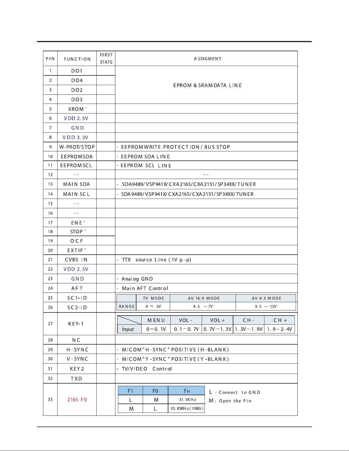
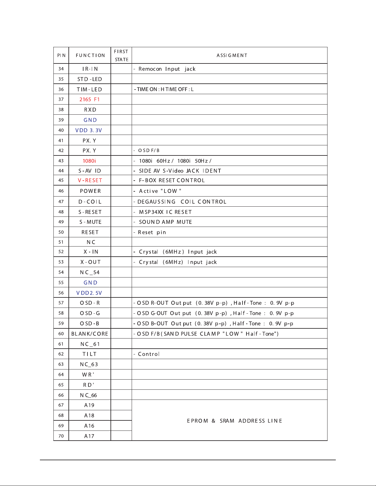
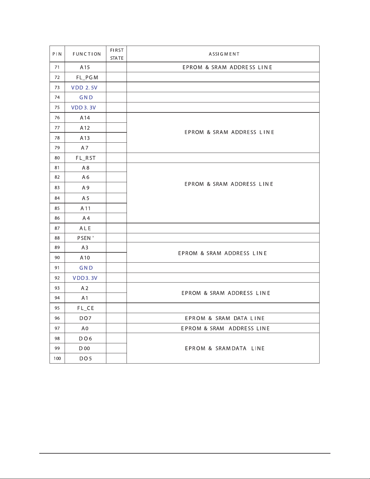
2-2 MICOM PORT
Page 5
Alignment and Adjustments
Samsung Electronics 2-5
Page 6
Alignment and Adjustments
2-6 Samsung Electronics
Page 7

Alignment and Adjustments
Samsung Electronics 2-7
2-3 Factory Adjustment
2-3-1 Factory Adjustment values
SERVICE
Deflection
Video Adjust1
Video Adjust2
Video Adjust3
Video Adjust4
YC Delay
EEPROM
Option
CheckSum
Reset
SERVICE
Deflection
480/576P Deflect offset
1080i Deflection offset
Video Adjust1
Video Adjust2
Video Adjust3
Video Adjust4
DTV Video Adjust
YC Delay
EEPROM
Option
CheckSum
Reset
European Model
The Others Model
Page 8
Alignment and Adjustments
2-8 Samsung Electronics
2-3-2 Factory Data
DEFLECTION : PAL
ITEMS
CIS
Europe China
Asia
M.Asia
REMARK
29”
32”
34"
28" 29" 32” 29" 34" 29” 32” 34"
29”
32”
V-AMP 26 26
26 26
26
26 26
26 26
26
26 26
26 Vertical AMP adj( Gain Control)
V-SHIFT 30 30
30
30 30
30
30 30
30
30 30
30
30 Vertical Position adj (DC bias adj)
H-EW
33 33
33
33
33
33 33
33 33 33 33 33
33 Horizontal AMP adj(Gain Control)
H-SHIFT 35 35 35 35 35 35 35 35
35
35 35
35
35 Horizontal Position adj (DC bias adj)
V-Linearity 6 6
6
6
6
6 5
5 6 6 6 6
6 Vertical Linearity adj(TOP/Bottom adj)
UP-Linearity 8
8
8
8 8 8 8
8 8
8 8
8
8 Vertical Linearity adj(TOP adj)
LOW-Linearity 4 4
4
4
4
4 4
4 4 4 4 4
4 Vertical Linearity adj(Bottom adj)
V-SC 5
5
5 5 5 5 5
5 5
5 5
5
5 Vertical S correction adj
H-Parablar 48 48
48
48
48 48
48
48 48 48 48 48
48 Horizontal pin distortion adj
UP-Coner 35
35
35 35 35 35 35
35 35
35 35
35
35 Horizontal pin distortion up adj
LOW-Coner 36 36
36
36
36 36
36
36 36 36 36 36
36 Horizontal pin distortion low adj
H-Trapezium
12
12
12 12 12 12 12
12 12
12 12
12
12 Horizontal Trapezium distortion adj
BOW 31 31
31
31
31 31
31
31 31 31 31 31
31 Vertical line slope adj(parabola)
ANGLE 25
25
25
25 25 25 25
25 25
25 25
25
25 Vertical Linearity adj(sawtooth)
V-Position 40 40
40
40
40 40
40
40 40 40 40 40
40 V-POSITION ADJ as to CRT INCH
CXA 2151 Sub01
68 68
68
68 68 68 68
68 68
68 68
68
68
CXA 2151 Sub02 1 1
1 1
1 1
1
1 1 1 1 1
1
Page 9

Alignment and Adjustments
Samsung Electronics 2-9
DEFLECTION : NTSC
ITEMS
CIS
Europe
China
Asia M.Asia
REMARK
29” 32”
34"
28"
29" 32”
29" 34" 29”
32”
34" 29” 32”
V-AMP
0
0
0 0 0 0 0 0 0 0
0
0 0 Vertical AMP adj( Gain Control)
V-SHIFT
2 2 2 2
2
2
2 2 2
2
2 2 2 Vertical Position adj (DC bias adj)
H-EW
1
1 1 1 1 1 1 1 1 1
1
1 1 Horizontal AMP adj(Gain Control)
H-SHIFT
9 9 9 9
9 9
9 9 9
9
9 9 9 Horizontal Position adj (DC bias adj)
V-Linearity 2 2 2 2 2 2 2 2 2 2 2 2 2 Vertical Linearity adj(TOP/Bottom adj)
UP-Linearity
1
1 1
1
1 1
1 1 1
1
1 1 1 Vertical Linearity adj(TOP adj)
LOW-Linearity -1
-1
-1 -1
-1
-1 -1 -1 -1 -1 -1 -1 -1 Vertical Linearity adj(Bottom adj)
V-SC
0 0
0
0
0 0 0
0 0
0
0 0 0 Vertical S correction adj
H-Parablar
0 0
0
0 0 0 0 0 0 0 0 0 0 Horizontal pin distortion adj
UP-Coner
2 2 2
2 2 2 2
2 2
2
2 2 2 Horizontal pin distortion up adj
LOW-Coner 3 3 3 3 3 3 3 3 3 3 3 3 3 Horizontal pin distortion low adj
H-Trapezium
-8 -8
-8 -8 -8 -8 -8
-8 -8
-8
-8 -8 -8 Horizontal Trapezium distortion adj
BOW
1 1
1
1
1
1 1 1 1 1 1 1 1 Vertical line slope adj(parabola)
ANGLE
-3 -3
-3 -3 -3 -3 -3
-3 -3
-3
-3 -3 -3
Vertical Linearity adj(sawtooth)
V-Position 0 0 0 0
0
0 0 0 0 0 0 0 0 V-POSITION ADJ as to CRT INCH
CXA 2151 Sub01
68 68
68 68 68 68 68
68 68
68
68 68
68
CXA 2151 Sub02
1 1 1 1
1
1 1 1 1 1 1 1 1
Page 10

Alignment and Adjustments
2-10 Samsung Electronics
Video Adjust 1
ITEMS
CIS
Europe
China
Asia
M.Asia
REMARK
29” 32” 34" 28" 29" 32” 29" 34" 29” 32” 34" 29” 32”
EE_R_CUTOFF, 35 35
35
35 35
35 35
35 35
35
35 35
35
R-cutoff control adj
EE_G_CUTOFF, 25 25
25
25 25 25 35 35 25 25 25 25 25 G-cutoff control adj
EE_B_CUTOFF, 40 40
40 40
40
40 40
40 40
40
40 40
40
B-cutoff control adj
Color On / Off 1 1
1
1 1 1 1 1 1 1 1
1
1 Initial Value : "0"--> 1
CR Offset 30 30
30
30
30
30 30
30 30
30
30 30
30
DC-offset canceling
CB Offest 30 30
30
30 30 30 30 30
30
30 30
30
30 DC-offset canceling
R Drive 32 32
32
32
32
32 32
32 32 32 32 32
32
R-Drive control adj
G Drive 25 25
25
25 25 25 28 28
25
25 25
25
25 G-Drive control adj
B Drive 41 41
41
41
41
41 41
41 41 41 41 41
41
B-Drive control adj
Sub Bright 48
48
48
48 48 48 48
48 48
48 48
48
48 Sub-Bright control
Sub Contrast 9 9
9 9
9
9 9
9 9 9 9 9
9
Sub-Contrast control
Sub Color 10
10
10
10 10 10 10
10 10
10 10
10
10 color gain control(PAL SETTING AGAIN)
Secam sub color 5 5
5
5
5 5
5
5 5 5 5 5
5
HUE control
Sub Tint 28
28
28
28 28 28 28
28 28
28 28
28
28 Chrominance Transient Improvement
CTI Level 2 2
2 2
2 2
2
2 2 2 2 2
2
color detection axis setting(NTSC/USA)
Color AXIS 1
1
1
1 1 1 1
1 1
1 1
1
1 Luminance Transient Improvement
LTI Level 1 1
1
1
1 1
1
1 1 1 1 1
1
vertical osd position
Page 11

Alignment and Adjustments
Samsung Electronics 2-11
Video Adjust 2
ITEMS
CIS
Europe China
Asia
M.Asia
REMARK
29” 32” 34"
28" 29"
32”
29" 34" 29” 32”
34"
29” 32”
ABL Mode 3 3 3 3 3 3 3
3
3 3 3 3 3
picture/bright ABL gain control(P AL SETTING AGAIN)
Gamma
2
2
2 2 2
2 3
3 2 2 2 2
2
RGB output correction control(PAL SETTING AGAIN)
DPIC Level 3
3
3 3 3 3 3 3 3 3 3 3 3
Dynamic picture black expansion control(PAL SETTING AGAIN)
DC Trans 2 2 2 2 2 2 2 2 2 2 2 2 2
Y-System DC transmission ratio(PAL SETTING AGAIN)
ABL-TH
14 14
14 14 14 14 14
14
14
14
14
14
14
Threshold voltage adj ABL-IN(PAL SETTING AGAIN)
VM-Level 2 2 2 2 2 2 2 2 2 2 2 2 2
VM-OUT Level control
VM-Coring
2 2
2 2 2 2 2
2
2
2 2 2
2
VM-OUT coring control
VM-f0 2 2 2 2 2 2 2 2 2 2 2 2 2
VM-f0 control
VM-Limit
2
2 2 2 2 2 2
2
2
2
2
2
2
VM-Limit level control
VM-Delay
3
3
3 3 3 3 3 3 3 3 3 3 3
VM-OUT phase control(reference to R-OUT)
SHP CD 1 1 1 1 1 1 1
1
1
1
1
1
1
Sharpness gain control(color satuation)
SHP f0
0
0
0 0 0 0 0 0 0 0 0 0 0
Sharpness f0 control (3Mhz)
SHP f1& p/o 8
8
8 8 8 8 8 8 8
8
8
8
8
Sharpness gain control(PAL SETTING AGAIN)
AKB Time
15 15 15 15 15 15 15 15 15 15 15 15 15
AKB Bch reference pulse time control(PAL SETTING AGAIN)
Coring 0 0 0 0 0 0 0 0 0
0
0
0
0
Bandpass
7
7
7 7 7
7
7 7 7 7 7 7 7
VSP9402 Band/High pass filter(Peaking)
Highpass 8 8 8 8 8 8 10 10 8
8
8
8
8
VSP9402 High pass filter
Page 12

Alignment and Adjustments
2-12 Samsung Electronics
Video Adjust 3
ITEMS
CIS
Europe China Asia M.Asia
REMARK
29” 32” 34"
28"
29" 32”
29"
34" 29” 32”
34" 29”
32”
H_EHT comp
4 4 4 4 4 4 3
3 4
4 4 4 4
H-EHT compensation setting(PAL SETTING AGAIN)
V_EHT comp 7
7 7
7 7 7
7
7
7
7
7 7 7
V-EHT compensation setting(PAL SETTING AGAIN)
PIN EHT comp 1 1 1 1 1 1 1 1
1
1
1 1
1 PIN-EHT compensation setting
AFC EHT comp
0
0 0
0 0 0
0
0
0
0
0 0 0
(P AL SETTING AGAIN)
Sync Phase 0 0 0 0 0 0 0 0 0 0
0 0
0 AFC-EHT compensation
NR Value
6
6 6
6 6 6
6
6
6
6
6 6 6
WHEN USED 74HC123
PIP Contrast
13 13 13 13 13 13
13
13 13 13
13 13
13 Not used
PIP Bright 0
0 0
0 0
0 0
0
0
0
0 0 0
PIP Tint 63 63 63 63 63 63 63 63 63 63
63 63
63
PIP Color 6
6 6
6 6
6 6
6 6 6
6 6 6
PIP Pal V Pos 28 28 28 28 28 28 28 28 28 28
28 28
28
PIP NTSC V Pos
25
25 25
25
25 25 25
25
25 25 25 25 25
PIP H Pos 34 34 34 34 34 34 34 34 34 34
34 34
34
PIP R Cut off 1
1 1
1
1 1 1
1
1
1
1 1 1
PIP G Cut off 1 1 1 1 1 1 1 1 1 1
1 1
1
PIP B Cut off
1 1 1
1
1 1 1
1
1
1
1 1 1
PIP R Drive 56 56 56 56 56 56 56 56 56 56
56 56
56
Page 13

Alignment and Adjustments
Samsung Electronics 2-13
YC Delay
Video Adjust 4
ITEMS
CIS Europe China Asia M.Asia
REMARK
29” 32” 34" 28" 29" 32” 29" 34" 29” 32” 34" 29” 32”
3Pip Pal V position 11 11 11 11 11 11 11 11 11 11 11 11 11
PIP Option
3Pip Pal H Position 13 13 13 13 13 13 13 13 13 13 13 13 13
PIP Option
3Pip Ntsc V Position 12 12 12 12 12 12 12 12 12 12 12 12 12
PIP Option
3Pip Ntsc H Position 19 19 19 19 19 19 19 19 19 19 19 19 19
PIP Option
Sync Phase (480p) 1 1 1 1 1 1 1 1 1 1 1 1 1
DTV Option
Sync Phase (576p) 1 1 1 1 1 1 1 1 1 1 1 1 1
DTV Option
Sync Phase (1080i) 0 0 0 0 0 0 0 0 0 0 0 0 0
DTV Option
ITEMS
CIS Europe China Asia M.Asia
REMARK
29” 32” 34" 28" 29" 32” 29" 34" 29” 32” 34" 29” 32”
P.YC (AV) Delay -9 -9 -9 -9 -9 -9 -9 -9 -9 -9 -9 -9 -9
S.YC (AV) Delay -8 -8 -8 -8 -8 -8 -8 -8 -8 -8 -8 -8 -8
N.YC (AV) Delay -8 -8 -8 -8 -8 -8 -8 -8 -8 -8 -8 -8 -8
P.BG.YC Delay -8 -8 -8 -8 -8 -8 -8 -8 -8 -8 -8 -8 -8
P.DK.YC Delay -10 -10 -10 -10 -10 -10 -10 -10 -10 -10 -10 -10 -10
P.I.YC Delay -10 -10 -10 -10 -10 -10 -10 -10 -10 -10 -10 -10 -10
P.M.YC DELAY -9 -9 -9 -9 -9 -9 -9 -9 -9 -9 -9 -9 -9
P.L.YC Delay -8 -8 -8 -8 -8 -8 -8 -8 -8 -8 -8 -8 -8
S.BG.YC Delay -6 -6 -6 -6 -6 -6 -6 -6 -6 -6 -6 -6 -6
S.DK.YC Delay -8 -8 -8 -8 -8 -8 -8 -8 -8 -8 -8 -8 -8
Page 14

Alignment and Adjustments
2-14 Samsung Electronics
ITEMS
CIS Europe China Asia M.Asia
REMARK
29” 32” 34" 28" 29" 32” 29"
34"
29” 32”
34"
29” 32”
V Amp
-1 -1 -1 -1 -1 -1 -1 -1 -1 -1 -1 -1 -1
V_SHIFT -1 -1 -1 -1
-1
-1
-1 -1
-1
-1 -1
-1 -1
H EW 2
2 2 2 2 2 2 2 2 2 2 2 2
H Shift
-14 -14 -14 -14
-14
-14
-14 -14
-14
-14 -14
-14 -14
V Linearity -1 -1 -1 -1 -1 -1 -1 -1 -1 -1 -1 -1 -1
Upper-Linearity 0 0 0 0
0
0
0 0
0
0 0
0 0
Lower-Linearity 0
0 0 0 0 0 0 0 0 0 0 0 0
V SC 0 0 0 0
0
0
0 0
0
0 0
0 0
H Parablar 0 0 0 0
0
0 0
0
0 0 0 0 0
Upper Corner 4 4 4
4 4
4 4
4
4
4 4
4 4
Lower Corner -3 -3 -3 -3
-3
-3
-3
-3 -3 -3 -3 -3 -3
H Trapezium
11 11
11 11 11
11
11 11
11
11 11
11 11
Bow 0 0 0 0
0
0 0
0
0 0 0 0 0
Angle 0 0
0 0 0
0
0 0
0
0 0
0 0
V Position 0 0 0 0
0
0
0 0
0 0 0 0 0
CXA 2151 Sub01
232 232
232 232 232
232
232 232
232
232 232
232 232
CXA 2151 Sub02 97
97 97 97
97
97
97 97
97 97 97 97 97
480p Deflection OFFSET
Page 15

Alignment and Adjustments
Samsung Electronics 2-15
ITEMS
CIS
Europe China
Asia M.Asia
REMARK
29” 32”
34" 28"
29"
32” 29" 34" 29” 32”
34"
29” 32”
V Amp 1
1 1
1 1 1
1 1 1
1 1
1
1
V_SHIFT
1 1
1 1
1
1 1 1 1 1 1 1 1
H EW
0 0
0
0 0 0
0 0 0
0 0
0
0
H Shift
-3
-3 -3 -3
-3
-3 -3 -3 -3 -3 -3 -3 -3
V Linearity
0
0 0
0 0 0
0 0 0
0 0 0 0
Upper-Linearity 0
0 0 0
0
0 0 0 0 0 0 0 0
Lower-Linearity
0
0 0
0 0 0
0 0 0
0 0
0
0
V SC 0 0
0 0
0
0 0 0 0 0 0 0 0
H Parablar 0
0 0
0 0 0
0 0 0
0 0
0
0
Upper Corner
0
0 0 0 0 0 0 0 0 0 0 0 0
Lower Corner
1
1 1
1 1 1
1 1 1
1 1
1
1
H Trapezium 6
6
6 6 6 6 6 6 6 6 6 6 6
Bow
0
0 0
0 0 0
0 0 0
0 0
0
0
Angle
2 2 2 2 2 2 2 2 2 2 2 2 2
V Position 0
0 0
0 0 0
0 0 0
0 0
0
0
CXA 2151 Sub01
232
232 232
232 232 232 232 232 232 232 232 232 232
CXA 2151 Sub02
97
97 97
97 97
97 97 97 97 97
97
97
97
576p Deflection OFFSET
Page 16

Alignment and Adjustments
2-16 Samsung Electronics
ITEMS
CIS
Europe
China Asia M.Asia
REMARK
29”
32” 34" 28" 29"
32” 29"
34" 29”
32” 34"
29” 32”
V Amp
3
3 3 3 3 3 3 3 3 3 3 3 3
V_SHIFT -3 -3 -3 -3 -3 -3 -3
-3 -3
-3 -3
-3 -3
H EW
-11
-11 -11 -11 -11 -11 -11 -11 -11 -11 -11 -11 -11
H Shift 8 8
8
8 8 8 8
8 8
8 8
8 8
V Linearity
-2
-2
-2
-2 -2 -2 -2 -2 -2 -2 -2 -2 -2
Upper-Linearity 0 0
0
0 0 0 0
0 0
0 0
0 0
Lower-Linearity 0
0 0 0 0
0
0 0 0 0 0 0 0
V SC -1 -1
-1
-1 -1 -1 -1
-1 -1
-1 -1
-1 -1
H Parablar -9
-9 -9 -9 -9
-9
-9 -9 -9 -9 -9 -9 -9
Upper Corner 1 1
1
1 1 1 1
1 1
1 1
1 1
Lower Corner -5
-5 -5 -5 -5
-5
-5 -5 -5 -5 -5 -5 -5
H Trapezium 10 10
10
10 10 10 10
10 10
10 10
10 10
Bow 2
2 2 2 2
2
2 2 2 2 2 2 2
Angle 1 1 1 1 1 1 1
1 1
1 1
1 1
V Position 0
0
0 0 0
0
0 0
0
0 0 0 0
CXA 2151 Sub01 196 196 196 196 196 196 196
196 196
196 196
196 196
CXA 2151 Sub02 97
97 97 97 97
97
97 97 97 97 97 97 97
1080I Deflection OFFSET
Page 17

Alignment and Adjustments
Samsung Electronics 2-17
ITEMS
CIS
Europe China
Asia
M.Asia
REMARK
29” 32” 34" 28" 29" 32” 29" 34" 29” 32” 34" 29” 32”
Sub Bright
10
10 10
10
10
10 10
10 10
10
10 10
10
Sub Contrast 6 6 6 6 6 6 6 6 6 6 6 6 6
Sub Color
15
15 15
15 15 15 15
15 15
15
15 15
15
Sub Tint (Hue)
25
25
25 25 25 25 25 25 25 25 25 25 25
Color AXIS
1
1 1
1 1
1
1
1 1
1
1 1
1
LTI Level
2
2
2 2 2 2 2 2 2 2 2 2 2
VM-Level
1
1
1
1
1 1
1
1 1
1
1 1
1
VM-Coring 2 2 2 2 2 2 2 2 2 2 2 2 2
VM-f0
2
2 2
2
2 2
2
2 2
2
2 2
2
VM-Limit
2
2 2 2 2 2 2 2 2 2 2 2 2
VM-Delay
3
3 3
3
3 3
3
3 3
3
3 3
3
SHP CD
1
1 1 1 1 1 1 1 1 1 1 1 1
SHP f0
0
0
0 0
0
0 0
0 0
0
0 0
0
SHP f1& p10 8 8 8 8 8 8 8 8 8 8
8
8 8
DTV Adjust(1080i)
Page 18

Alignment and Adjustments
2-18 Samsung Electronics
ITEMS
CIS
Europe China
Asia
M.Asia
REMARK
29” 32” 34" 28" 29" 32” 29" 34" 29” 32” 34" 29” 32”
Sub Bright
12
12 12
12
12
12 12
12 12
12
12 12
12
Sub Contrast 7 7 7 7 7 7 7 7 7 7 7 7 7
Sub Color
12
12 12
12 12 12 12
12 12
12
12 12
12
Sub Tint (Hue)
26
26
26 26 26 26 26 26 26 26 26 26 26
Color AXIS
1
1 1
1 1
1
1
1 1
1
1 1
1
LTI Level
1
1
1 1 1 1 1 1 1 1 1 1 1
VM-Level
1
1
1
1
1 1
1
1 1
1
1 1
1
VM-Coring 2 2 2 2 2 2 2 2 2 2 2 2 2
VM-f0
2
2 2
2
2 2
2
2 2
2
2 2
2
VM-Limit
2
2 2 2 2 2 2 2 2 2 2 2 2
VM-Delay
3
3 3
3
3 3
3
3 3
3
3 3
3
SHP CD
1
1 1 1 1 1 1 1 1 1 1 1 1
SHP f0
0
0
0 0
0
0 0
0 0
0
0 0
0
SHP f1& p10 8 8 8 8 8 8 8 8 8 8
8
8 8
DTV Adjust(576P/480P)
Page 19

Alignment and Adjustments
Samsung Electronics 2-19
Option Byte
ITEMS
CIS Europe
China Asia
M.Asia
REMARK
29”/34”
32" 29" 28"/32” 29"/34" 29”/34” 32" 29” 32”
CRT
4;3 Wide 4:3 Wide 4;3
4;3 Wide
4;3 Wide
4:3,WIDE
Osd Group CIS - China
East Asia
Arab or Persia CIS,Arab,Persia, Europe,East Asia,China
OSD Language Russian
- chinese
Engilish
Engilish
Pertinent language
AV-Jack Scart Scart Rca
Rca
Rca(Scart) SCART(CIS,EUROPE)/RCA(ASIA,AUSTRAILIA)
DTV
No No Yes
No
No
DTV S/W data control
PIP 2-tuner
off off
2-tuner
2-tuner "off","1-tuner","2-tuner"
LNA
On off off
On
On
On : 2T PIPAll Model Off: 1TUNER / No PIP
SEARCH_LNA On
off off
On
On
On : 2T PIP LNA All Model
Off: 1TUNER / No PIP"
SOUND Virtual Dolby
Virtual Dolby Virtual Dolby
Virtual Dolby
Virtual Dolby
V-DOLBY/A2-NICAM
Auto FM On
On On
On
On
On : FM Auto change(All model)
Off : MODE ON(Currently nothing)
Carrier mute
Off
On
Off Off
Off
On:Europe/Italy Off:Other
HIGH Deviation
Off Off On
Off
Off ON : INDIA ,KOREA Other : OFF
Woofer Off
Off
Off Off
Off
TTX Group
Russian
Osd Language west europe
west europe
west europe
TTX Language Group
TTX TOP Off
off Off
Off
Off
ON : German,Swiss
OFF : Other Area
TTX LIST Off
off Off
Off
Off
ON : Australia
OFF : Other Area
TTX ON/OFF
On
off
Off off
Off
OFF/ON : TTX ON or OFF
DTV1080I 60HZ
60HZ 50HZ
60HZ
60HZ
50HZ: Australia,China
60HZ: Southeast Asia area
Digital NR On
On
On On On
ON : Digital NR ON
OFF :Digital NR OFF
AGC on/off
off
off off
off
off
ON : sync In standard AGC
gain control(Overflow control)
OFF : AGC gain fixed value
Tilt on/off ON
ON ON
ON
ON
ON : Tilt function ON (OSD display)
OFF : Tilt function OFF (OSD no display)
Page 20

Alignment and Adjustments
2-20 Samsung Electronics
EEPROM Data
No. Items
CIS Europe China Asia M.Asia
29” 32” 34" 28" 29" 32” 29" 34" 29” 32” 34" 29” 32”
0 System 1 1 1 1 1 1 1 1 1 1 1 1 1
1 - - - - - - - - - - - - 2 System (480p) 2 2 2 2 2 2 2 2 2 2 2 2 2
3 System (1080i) 3 3 3 3 3 3 3 3 3 3 3 3 3
4 Dynamic Contrast 100 100 100 100 100 100 100 100 100 100 100 100 100
5 Dynamic Brightness 50 50 50 50 50 50 50 50 50 50 50 50 50
6 Dynamic Shapness 55 55 55 55 55 55 55 55 55 55 55 55 55
7 Dynamic Color 50 50 50 50 50 50 50 50 50 50 50 50 50
8 Dynamic Tint 50 50 50 50 50 50 50 50 50 50 50 50 50
9 Dynamic Color Tone
10 Standard Contrast 70 70 70 70 70 70 70 70 70 70 70 70 70
11 Standard Brightness 50 50 50 50 50 50 50 50 50 50 50 50 50
12 Standard Shapness 50 50 50 50 50 50 50 50 50 50 50 50 50
13 Standard Color 50 50 50 50 50 50 50 50 50 50 50 50 50
14 Standard Tint 50 50 50 50 50 50 50 50 50 50 50 50 50
15 Standard Color Tone - - - - - - - - - - - - 16 Movie Contrast 40 40 40 40 40 40 40 40 40 40 40 40 40
17 Movie Brightness 50 50 50 50 50 50 50 50 50 50 50 50 50
18 Movie Shapness 40 40 40 40 40 40 40 40 40 40 40 40 40
19 Movie Color 45 45 45 45 45 45 45 45 45 45 45 45 45
20 Movie Tint 50 50 50 50 50 50 50 50 50 50 50 50 50
21 Movie Color Tone - - - - - - - - - - - - 22
23
24
25
26
Left Blanking
(480p)
215 215 215 215 215 215 215 215 215 215 215 215 215
Page 21

Alignment and Adjustments
Samsung Electronics 2-21
No. Items
CIS Europe China Asia M.Asia
29” 32” 34" 28" 29" 32” 29" 34" 29” 32” 34" 29” 32”
27
Right Blanking
(480p)
169 169 169 169 169 169 169 169 169 169 169 169 169
28
Left Blanking
(1080i)
141 141 141 141 141 141 141 141 141 141 141 141 141
29
Right Blanking
(1080i)
109 109 109 109 109 109 109 109 109 109 109 109 109
30 Brightness (RGB) 236 236 236 236 236 236 236 236 236 236 236 236 236
31 Contrast (RGB) 169 169 169 169 169 169 169 169 169 169 169 169 169
32 U Saturation (RGB) 94 94 94 94 94 94 94 94 94 94 94 94 94
33 V Saturation (RGB) 36 36 36 36 36 36 36 36 36 36 36 36 36
34
DVD Brightness
(YPbPr)
221 221 221 221 221 221 221 221 221 221 221 221 221
35
DVD Contrast
(YPbPr)
166 166 166 166 166 166 166 166 166 166 166 166 166
36
DVD U Saturation
(YPbPr)
122 122 122 122 122 122 122 122 122 122 122 122 122
37
DVD V Saturation
(YPbPr)
57 57 57 57 57 57 57 57 57 57 57 57 57
38 9402 Y Gain 175 175 175 175 175 175 175 175 175 175 175 175 175
39 9402 U Gain 71 71 71 71 71 71 71 71 71 71 71 71 71
40
41 9402 V Gain 65 65 65 65 65 65 65 65 65 65 65 65 65
42 CrCb Gain (480p) 119 119 119 119 119 119 119 119 119 119 119 119 119
43 CrCb Gain (1080i) 119 119 119 119 119 119 119 119 119 119 119 119 119
44 LTI Mode 2 2 2 2 2 2 2 2 2 2 2 2 2
45
46 LTI Mode (480p) 1 1 1 1 1 1 1 1 1 1 1 1 1
47 LTI Mode (1080i) 1 1 1 1 1 1 1 1 1 1 1 1 1
48 NR ON value1 85 85 85 85 85 85 85 85 85 85 85 85 85
49 NR ON value2 85 85 85 85 85 85 85 85 85 85 85 85 85
50 NR OFF value1 68 68 68 68 68 68 68 68 68 68 68 68 68
51 NR OFF value2 68 68 68 68 68 68 68 68 68 68 68 68 68
52 NR ON value3 170 170 170 170 170 170 170 170 170 170 170 170 170
53 NR ON value4 170 170 170 170 170 170 170 170 170 170 170 170 170
Page 22

Alignment and Adjustments
2-22 Samsung Electronics
No. Items
CIS Europe China Asia M.Asia
29” 32” 34" 28" 29" 32” 29" 34" 29” 32” 34" 29” 32”
54 NR OFF value3 34 34 34 34 34 34 34 34 34 34 34 34 34
55 NR OFF value4 34 34 34 34 34 34 34 34 34 34 34 34 34
56
57 SECAM Sensitivity 28 28 28 28 28 28 28 28 28 28 28 28 28
58 Range of R Gain 32 32 32 32 32 32 32 32 32 32 32 32 32
59 Range of G Gain 32 32 32 32 32 32 32 32 32 32 32 32 32
60 Range of B Gain 32 32 32 32 32 32 32 32 32 32 32 32 32
61 Range of F/B Gain 23 23 23 23 23 23 23 23 23 23 23 23 23
62
63 TTX V-Position 40 40 40 40 40 40 40 40 40 40 40 40 40
64 TTX H-Position 180 180 180 180 180 180 180 180 180 180 180 180 180
65
66
67
wide model 4:3
Normal Parabola
0 0 0 0 0 0 0 0 0 0 0 0 0
68
1080i 50HZ
Trepezium
- - - - - - - - - - - - -
69
1080i 60HZ
Trepezium
- - - - - - - - - - - - -
70
UP-UCG (Up
Corner Semi
Control)
0 0 0 0 0 0 0 0 0 0 0 0 0
71
LO-UCG (Low
Corner Semi
Control)
0 0 0 0 0 0 0 0 0 0 0 0 0
72
Vertical Slicing Level
Threshold
15 15 15 15 15 15 15 15 15 15 15 15 15
73
Vertical Sync
Lowpass-Filter
13 13 13 13 13 13 13 13 13 13 13 13 13
74
Amplifier Current
Setting of Oscillator
Pad
2 2 2 2 2 2 2 2 2 2 2 2 2
75 PAL 185 185 185 185 185 185 185 185 185 185 185 185 185
76 Chroma (PAL) 215 215 215 215 215 215 215 215 215 215 215 215 215
Page 23

Alignment and Adjustments
Samsung Electronics 2-23
No. Items
CIS Europe China Asia M.Asia
29” 32” 34" 28" 29" 32” 29" 34" 29” 32” 34" 29” 32”
77
Chroma PLL adj is
("0" Auto PLL, "0")
- - - - - - - - - - - - -
78 WSS 4:3 Panorama - - - - - - - - - - - - 79 NT left blank 79 79 79 79 79 79 79 79 79 79 79 79 79
80 NT Right blank 126 126 126 126 126 126 126 126 126 126 126 126 126
81
Progressive TTX V
Position
- - - - - - - - - - - - -
82
Progressive TTX H-
Position
- - - - - - - - - - - - -
83 Cr gain(480p) 46 46 46 46 46 46 46 46 46 46 46 46 46
84 Cb gain(480p) 35 35 35 35 35 35 35 35 35 35 35 35 35
85 Cr gain(576p) 43 43 43 43 43 43 43 43 43 43 43 43 43
86 Cr gain(576p) 30 30 30 30 30 30 30 30 30 30 30 30 30
87 Cr gain(1080i) 22 22 22 22 22 22 22 22 22 22 22 22 22
88 Cb gain(1080i) 27 27 27 27 27 27 27 27 27 27 27 27 27
89
90 RF SubBright 124 124 124 124 124 124 124 124 124 124 124 124 124
91
TTX Sub
Brightness°ª
235 235 235 235 235 235 235 235 235 235 235 235 235
92 Left Blanking 101 101 101 101 101 101 101 101 101 101 101 101 101
93 Right Blanking 153 153 153 153 153 153 153 153 153 153 153 153 153
94 S - ABL 0 0 0 0 0 0 0 0 0 0 0 0 0
95 P - ABL 48 48 48 48 48 48 48 48 48 48 48 48 48
96 Picture Limit Level 3 3 3 3 3 3 3 3 3 3 3 3 3
97
OSD Level
(LRGB2_LEV)
5 5 5 5 5 5 5 5 5 5 5 5 5
98
TTX Level
(LRGB2_LEV)
3 3 3 3 3 3 3 3 3 3 3 3 3
99 AGCADJ1 238 238 238 238 238 238 238 238 238 238 238 238 238
Page 24

Alignment and Adjustments
2-24 Samsung Electronics
No. Items
CIS Europe China Asia M.Asia
29” 32” 34" 28" 29" 32” 29" 34" 29” 32” 34" 29” 32”
100 AGCADJ2 110 110 110 110 110 110 110 110 110 110 110 110 110
101
ON TIMER CH
memory
1 1 1 1 1 1 1 1 1 1 1 1 1
102
Component2 OSD
Brightness
10 10 10 10 10 10 10 10 10 10 10 10 10
196 TNR1 207 207 207 207 207 207 207 207 207 207 207 207 207
197 TNR2 175 175 175 175 175 175 175 175 175 175 175 175 175
198 TNR3 149 149 149 149 149 149 149 149 149 149 149 149 149
199 TNR4 127 127 127 127 127 127 127 127 127 127 127 127 127
200 TNR5 99 99 99 99 99 99 99 99 99 99 99 99 99
201 TNR6 31 31 31 31 31 31 31 31 31 31 31 31 31
202
203
204
205 HPLL timing 156 156 156 156 156 156 156 156 156 156 156 156 156
Page 25

Alignment and Adjustments
Samsung Electronics 2-25
2-4 Screen Change(I2C Bus Geometric Adjustment)
Page 26

2-26 Samsung Electronics
MEMO
 Loading...