

Samsung CS15K2X/BWT, CS2073S/NWT, CS15K8WX/VWT, CS2073S/BWT, CS2073S/VWT Service Manual
...
COLOR TELEVISION RECEIVER
Chassis : KS1A
Model : CS15K2X/BWT,NWT,VWT
CS15K8WX/BWT,NWT,VWT
CS2073S/BWT,NWT,VWT
CS21F5X/BWT,NWT,VWT
CS2173S/BWT,NWT,VWT
CS21D8S/NWT,BWT,VWT
CS21S1S/NWT,BWT,VWT
COLOR TELEVISION RECEIVER CONTENTS
Precautions
Specifications and IC Data
Disassembly and Reassembly
Alignment and Adjustment
Troubleshooting
Exploded View and Parts List
Electrical Parts List
Block Diagram
Wiring Diagram
Schematic Diagrams
1.
2.
3.
4.
5.
6.
7.
8.
9.
10.
SAMSUNGSAMSUNG
SAMSUNGSAMSUNG
2007.04.27
QQ :376315150
手机:13942296513

ELECTRONICS
© Samsung Electronics Co., Ltd. APR. 2001
Printed in Korea
3KS1A-1502
Samsung Electronics 2-1
Specifications and IC Data
2. Specifications and IC Data
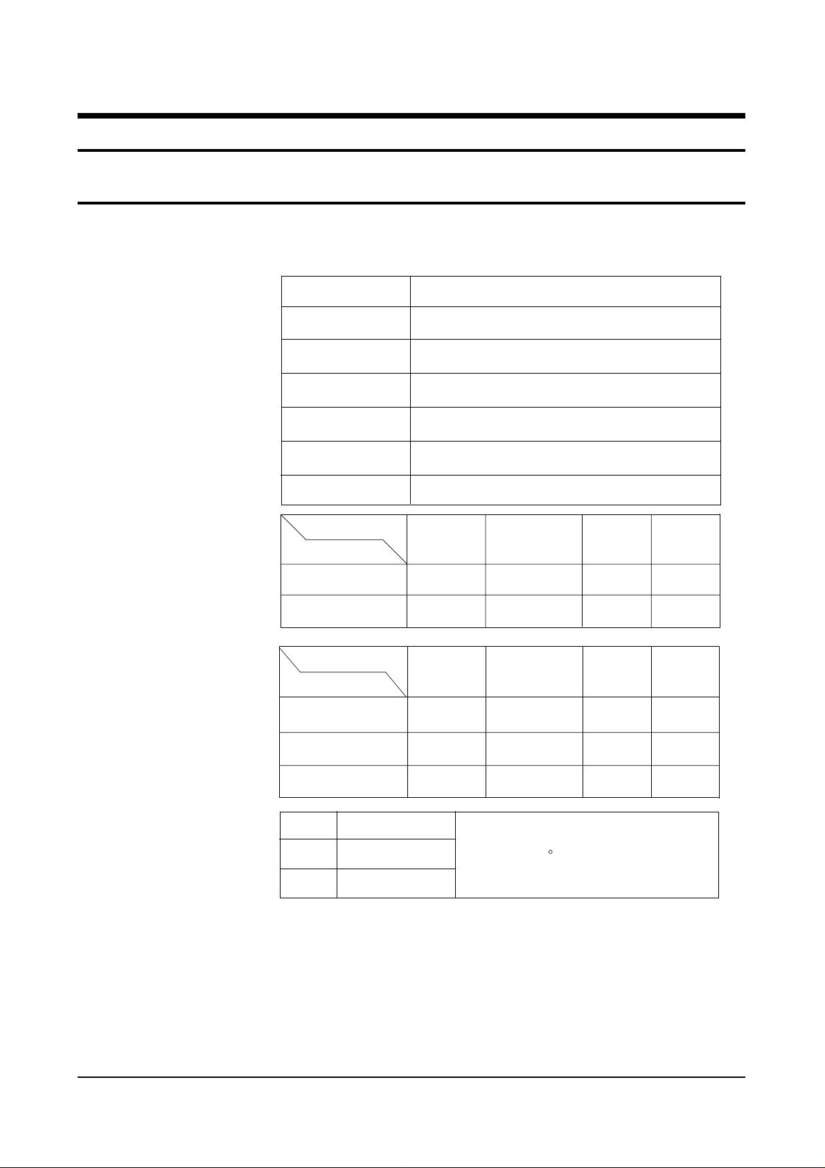
2-1 Specifications
Television System:
Channels:
Intermediate Frequencies (MHz) :
MODEL
CI
CII
CX
CK
CW
CS
System
Band
VHF
UHF
SYSTEM
IF Carrier Frequency
SYSTEM
PAL-I (UHF)
PAL-I (VHF/UHF)
PAL-B/G, SECAM-B/G
PAL-B/G, D/K, SECAM-B/G, D/K
PAL-B/G, D/K, SECAM-B/G, D/K, NT 4.43
PAL-B/G, D/K, SECAM-B/G, D/K, NT4.43, NT3.58
PAL/SECAM-
B/G,I
2 - 12
21 - 69
PAL/
SECAM- B/G
PAL,
SECAM- D/K
1 - 13
21 - 69
PAL/SECAM-D/K,
SECAM-K1
SECAM-K1,
PAL-D
2 - 9
13 - 57
PAL - I
NTSC - M
2 - 13
14-69
NTSC - M
Picture Tube:
Power Requirements:
Antenna Input Impedance:
Speaker Impedance
Picture IF Carrier
Sound IF Carrier
Color Sub Carrier
14 Inch
20 Inch
21 Inch
AC 100~240V, 50/60Hz
VHF, UHF : Telescopic dipole antenna (75 ohm unbalanced type )
8 ohm, 5W+5W (Dual Type)
16 ohm, 3W (Monitor Type & Dual Type)
A34KQV42X
A48KRD82X(H)
A51KQJ63X
38.90
33.40
34.47
Quick start, in-line-gun,
Black stripe, 90
38.90
32.40
34.47
degree deflection
38.90
32.90
34.47
38.90
34.40
35.32
2-2 Samsung Electronics
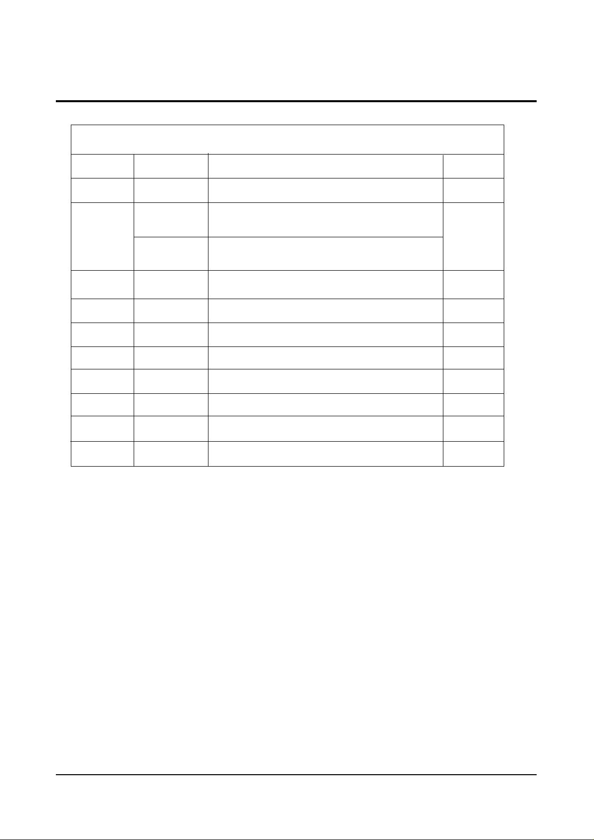
2-2 IC Line Up
Specifications and IC Data
Loc. No Specification Description Remark
HC101 PAP103 IF PRE-AMP
Table 2-1 IC Line-Up
SPM802ER
IC201S
SPM802ERN
IC301
IC501 TDA6107Q RGB DRIVE AMP
IC601
IC801S
IC802 KA7632
IC902 24C08/KS28C040 EEPROM
PC801S TCET1108 / LTV817B PHOTO COUPLER
IC101 U4468B
LA7840
TDA7266S
KA5Q0765R
TTX, English/Croatian/Romanian/Hungarian/Polish/Czech/
Bulgarian/Russian/Portugal
W/O TTX, English/Croatian/Romanian/Hungarian/Polish/Czech/
Bulgarian/Russian/Portugal
VERTICAL OUTPUT
SOUND-AMP (3W x 1CH or 3W x 2CH or 5W x 2CH)
POWER IC (STR)
CUSTOM REGULATOR (5V, 8V, 3.3V)
SIF - IC
Philips
Sanyo
Philips
TEMIC
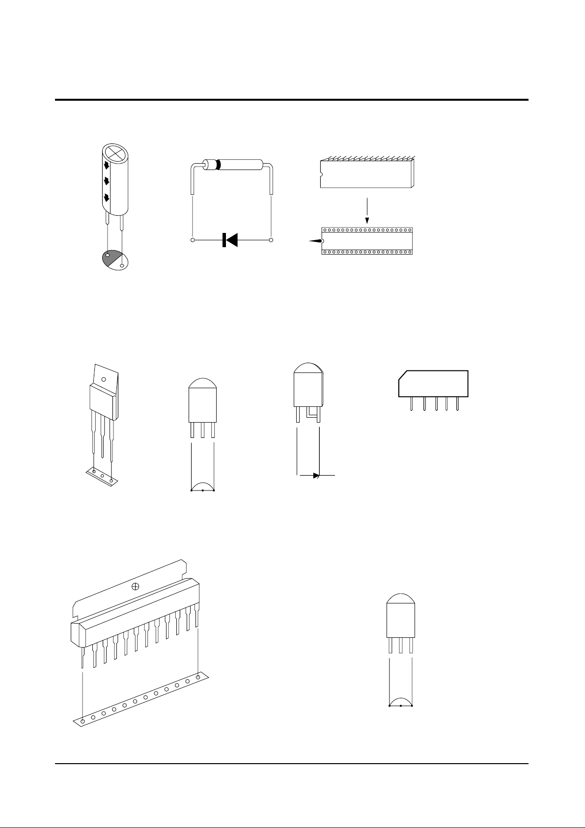
2-3 Semiconductor Base Diagrams
Specifications and IC Data
Samsung Electronics 2-3
Fig. 2-1 Semiconductor Base Diagrams
ELECTROLYTICCONDENSER
TRANSISTOR
TRANSISTOR
2SD1651
2SD1650
2SD2499
KSA614
DIODE
KSC815-Y
KSA539-Y
BC548
KTC9014
IC
SPM-802ERN(Pin 64)
SPM-802ER(Pin 64)
X24CO8P(Pin 8)
KS24C080(Pin 8)
U4468B(Pin 16)
IC
UPC574J
or
KA33V
SAW-FILTER
1
1
1
G3956M
K9260M
B
C
E
IC
E B C
TDA6107Q
KA7632
TRANSISTOR
LA7840
KSR1012
KSR1010
KSR2010
KTD863-Y
KSC2331-Y
E C B

2-4
MEMO

Alignment and Adjustments
Samsung Electronics 4-1
4. Alignment and Adjustments
4-1 Preadjustment
4-1-1 Factory Mode
1. Do not attempt these adjustments in the Video
Mode.
2. The Factory Mode adjustments are necessary
when either the EEPROM (IC902) or the CRT
is replaced.
3. Do not tamper with the “Adjustment” screen
of the Factory Mode menu. This screen is
intended only for factory use.
4-1-2 When EEPROM (IC902) Is Replaced
1. When IC902 is replaced all adjustment data
revert to initial values. It is necessary to
re-program this data.
2. After IC902 is replaced, warm up the TV for
10 seconds.
4-1-3 When CRT Is Replaced
1. Make the following adjustments AFTER setting up after setting up purity and convergence :
White Balance
Sub-Brightness
Vertical Center
Vertical Size
Horizontal Size
Fail Safe (This adjustment must be the last
step).
2. If the EEPROM or CRT is replaced, set PVAto
40 (factory mode) and set SC as follows.
14 inch : 0
20 inch : 9
21 inch : 9
4-2 Factory/Service Mode
4-2-1 Procedure for the “Adjustment” Mode
1. This mode uses the standard remote control.
The Service Mode is activated by entering the
following remote-control sequence :
(1) DISPLAY→FACTORY.
(2) STAND-BY→ DISPLAY→ MENU→ MUTE
→POWER ON.
2. The “SERVICE (FACTORY)” message will be
displayed. The Service Mode has four components: ADJUST, OPTION and Reset.
3. Access the Adjustment Mode by pressing the
“VOLUME” keys ( Up or Down). The adjustment parameters are listed in the accompanying table, and selected by pressing the CHANNEL keys (▲ ,▼).
4. Selection sequences for the all system:
DOWN or UP key:
SCT>SBT>BLR>BLB>RG>GG>BG>VSL>
VS>VA>HS>SC>SDL>STT>SSP>PDL>
NDL>PSR>NSR>AGC>VOL>LCO>TXP
5. The VOLUME keys increase or decrease the
adjustment values (stored in the
non-volatile memory) when Adjustment Mode
is cancelled.
6. Cancel the Adjustment Mode by re-pressing
the “FACTORY” or “Power OFF” keys.
4-2-2 Main Adjustment Parameter
NOTE : PVS,PVA, PHS, parameters must be aligned using the 50Hz vertical-field rates.
Alignment and Adjustments
4-2 Samsung Electronics
OSD FUNCTION RANGE INITIAL DATA REMARK
SCT Sub Co ntra s t 0~23
SBT Sub Bri g ht n e s s 0~23
BLR Bl ac k Le v el offset Blue 0~15
BLB Bl ac k Le v el offset Red 0~15
RG R e d G a i n 0~63
GG Green Gai n 0~63
BG Bl u e G ai n 0~63
VSL Ve rt i c al S lop e 0~63
VS Vert i ca l Shi f t 0~63
VA Ver t ical Am pli tude 0~63
HS Hori zontal Shif t 0~63
SC S- Co rr e ctio n 0~63
CDL Cat hode Drive Level 0~15
STT Sub Tint 0~7
SSP Sub Sharpness 0~7
PDL PAL De l ay 0~15
13
9
9
7
32
25(Fix)
31
19
38
40(Fix)
30
9
9
3
0
15(Fix)
NDL NTSC Delay 0~15
PSR PAL Sub c oloR 0~23
NSR NTSC Sub c oloR 0~23
AGC Automat ic Gain Cont rol 0~63
VOL Volume pre s et t i ng 0~63
LCO SECAM-L Vision I F 0~1
TXP TTX Posi tion 0~15
10
2
5
23
10
0
9
Alignment and Adjustments
Samsung Electronics 4-3
4-2-3 Option Bytes
In the Service Mode, various can be selected via the Option Table. Example:
Option Table : xx xx xx xx
1
2
3
4
5
6
7
8
9
10
LNA
SYSTEM
AUDIO
JACK
ZOOM
AUTO POWER
SBL
2nd SIF
HOTEL MODE
BKS
ON
CZ
MONO
RCA
NOR/ZOOM/16:9
ON
OFF
ON
OFF
ON

Alignment and Adjustments
4-4 Samsung Electronics
4-3 Other Adjustments
4-3-1 General
1. Usually, a color TV needs only slight touchup adjustment upon installation. Check the
basic characteristics such as height, horizontal
and vertical sync and focus.
2. The picture should have good black and white
details. There should be no objectionable
color shading; if color shading is present, perform the purity and convergence adjustments
described below.
3. Use the specified test equipment or its equivalent.
4. Correct impedance matching is essential.
5. Avoid overload. Excessive signal from a sweep
generator might overload the front-end of the
TV. When inserting signal markers, do not
allow the marker generator to distort test
results.
6. Connect the TV only to an AC power source
with voltage and frequency as specified on the
backcover nameplate.
7. Do not attempt to connect or disconnect any
wires while the TV is turned on. Make sure
that the power cord is disconnected before
replacing any parts.
8. To protect against shock hazard, use an isolation transformer.
4-3-2 Automatic Degaussing
A degaussing coil is mounted around the picture tube, so that external degaussing after
moving the TV should be unnecessary. But
the receiver must be properly degaussed upon
installation.
The degaussing coil operates for about 1 second after the power is switched ON. If the set
has been moved or turned in a different direction, disconnect its AC power for at least 30
minutes.
If the chassis or parts of the cabinet become
magnetized, poor color purity will result. If
this happens, use an external degaussing coil.
Slowly move the degaussing coil around the
faceplate of the picture tube and the sides and
front of the receiver. Slowly withdraw the coil
to a distance of about 6 feet before removing
power.
4-2-4 RESET
The Reset Mode is used during factory inspection.
Function Reset:
1. Picture Custom
2. Auto Volume Off
3. Color System Auto (option)
4. Sound System D/K (option)
5. Blue Screen Off
6. Low Noise AMP Off (option)
7. Volume 10
8. CH. Skip Erased
9. CH. Lock Off
10. Timer Off

Alignment and Adjustments
Samsung Electronics 4-5
4-3-3 High Voltage Check
CAUTION: There is no high voltage adjustment on this chassis.
The B+ power supply must be set to +125 volts (Full color bar input
and normal picture level).
1. Connect a digital voltmeter to the second
anode of the picture tube.
2. Turn on the TV. Set the Brightness and
Contrast controls to minimum (zero beam current).
3. The high voltage should not exceed 27.5KV.
4. Adjust the Brightness and contrast controls to
both extremes. Ensure that the high voltage
does not exceed 27.5KV under any conditions.
4-3-4 FOCUS Adjustment
1. Input a black and white signal.
2. Adjust the tuning control for the clearest pic-
ture.
3. Adjust the FOCUS control for well defined
scanning lines in the center area of the screen.
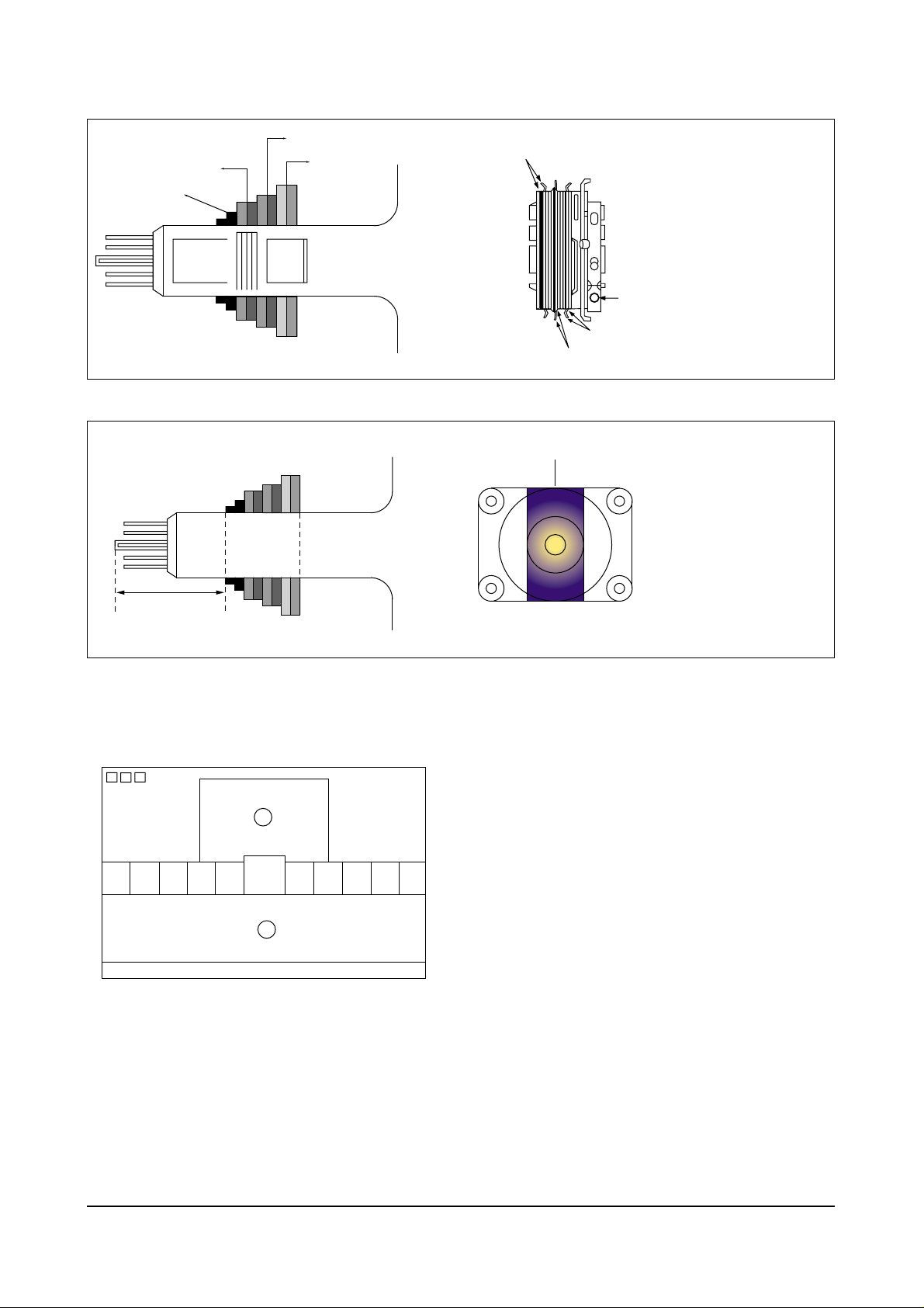
4-3-5 Cathode Voltage Adjustment
(Screen Adjustment)
1. Connect CRT socket pin GK to an oscilloscope
probe.
2. Input a gray scale pattern. (Use a pattern gen-
erator, PM5518)
3. Use the P mode key (on the remote control)
for the STANDARD picture.
4. Adjust the Screen VR (on the FBT) so that the
voltage on the oscilloscope becomes 120+2.5V
(See Fig. 4-1).
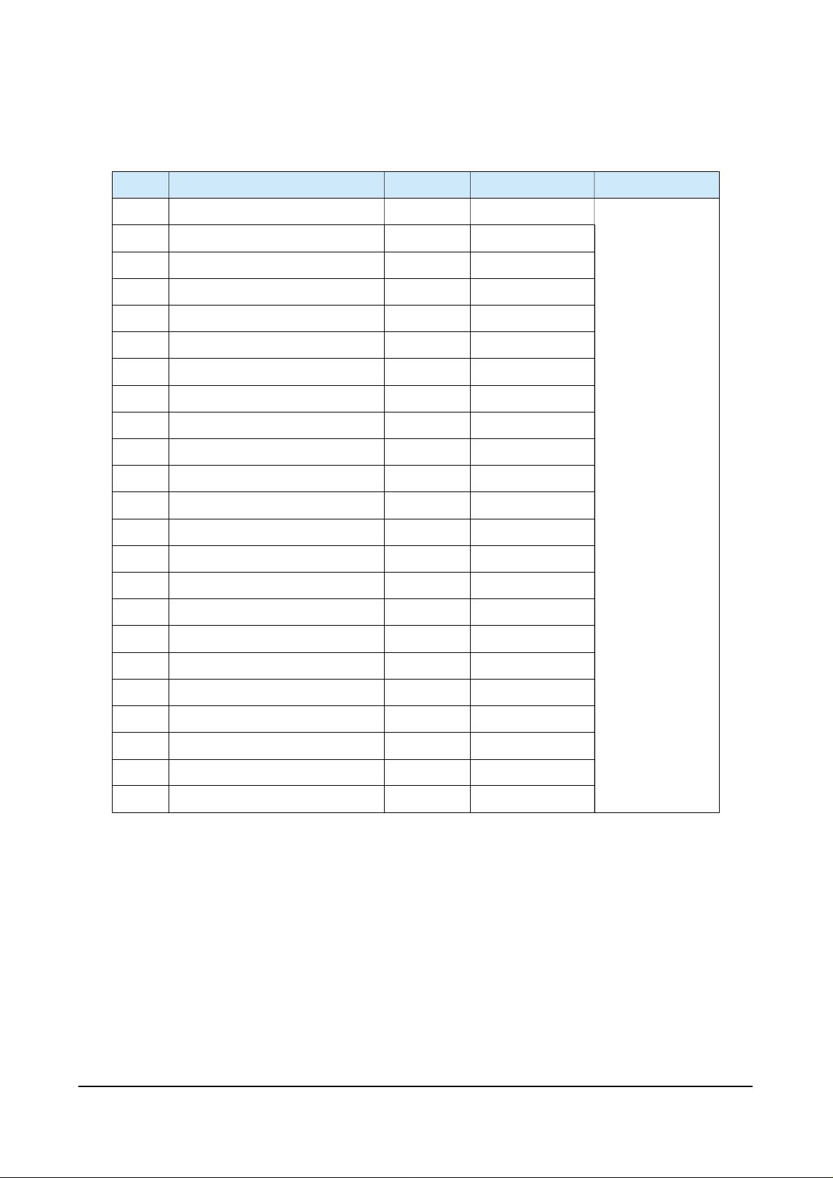
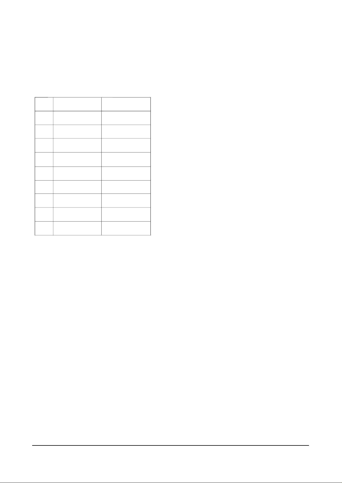
4-3-6 Purity Adjustment
1. Warm up the receiver for at least 20 minutes.
2. Plug in the CRT deflection yoke and tighten
the clamp screw.
3. Plug the convergence yoke into the CRT and
set in as shown in Fig. 4-2.
4. Input a black and white signal.
5. Fully demagnetize the receiver by applying an
external degaussing coil.
6. Turn the CONTRAST and BRIGHTNESS controls to maximum.
7. Loosen the clamp screw holding the yoke.
Slide the yoke backward or forward to provide vertical green belt. (Fig. 4-3).
8. Tighten the convergence yoke.
9. Slowly move the deflection yoke forward,
and adjust for the best overall green screen.
10. Temporarily tighten the deflection yoke.
11. Produce blue and red rasters by adjusting the
low-light controls. Check for good purity in
each field.
12. Tighten the deflection yoke.
Fig. 4-1
_
_
+
120 2.5V
GND
14" :120 2.5V
20, 21" : 120 2.5V
_
+
_
+
Alignment and Adjustments
4-6 Samsung Electronics
4-3-7 White Balance Adjustment
Fig. 4-2 Convergence Magnet Assembly
Fig. 4-3 Center Convergence Adjustment
Fig. 4-4
(a) Set up
1. Warm up the TV for at least 30 minutes in the
Aging Mode (OSD White). This mode is displayed by entering the following sequence:
DISPLAY
→FACTORY → FACTORY
2. Input a Toshiba pattern.
(b) Low-Light Adjustment
1. Set SBT to 3.5 ± 0.5 fL in the Factory Service
Mode with using CA100. See Fig. 4-4
➁.
2. Adjust RG,BG so that the levels are suitable to
each local area.
(c) High-Light Adjustment
1. Set SCT to 55 FL (20”. 21”), 65 FL(14”) in the
Factory Service Mode with using CA100. See
Fig. 4-4
①.
6 Pole Magnet
Clamper
Screw
4 Pole Magnet
2 Pole Magnet
2 POLE
PURITY
Vertical Green Belt
YOKE
CLAMP
SCREW
6 POLE
CONVERGENCE
4 POLE
CONVERGENCE
ADJUST THE ANGLE
(VERTICAL LINES)
31m/m
1
2
Alignment and Adjustments
Samsung Electronics 4-7
4-3-8 Center Convergence Adjustment
1. Warm up the receiver for at least 20 minutes.
2. Adjust the two tabs of the 4 pole magnets to
change the angle between them. Superimpose
the red and blue vertical lines in the center
area of the screen.
3. Adjust the Brightness and Contrast controls
for a well defined picture.
4. Adjust the two-tab pairs of the 4 pole magnets, and change the angle between them.
Superimpose the red and the blue vertical
lines in the center area of the screen.
5. Turn the both tabs at the same time, keeping
the angle constant, and superimpose the red
and blue horizontal line in the center of the
screen.
6. Adjust the two-tab pairs of the 6-pole magnets
to superimpose the red and blue line onto the
green. (Changing the angle affects the vertical
lines, and rotating both magnets affects the
horizontal lines.)
7. Repeat adjustments 2~6, if necessary.
8. Since the 4-pole magnets and 6-pole magnets
interact, the dot movement is complex
(Fig. 4-5).
Fig. 4-5 Center Convergence Adjustment
BLUE
BLUE
RED
RED
RED/BLUE
RED/BLUE
GREEN
GREEN
4-Pole Magnet Movement
6-Pole Magnet Movement
4-3-9 RF AGC Adjustment
Set the AGC data to 23 (Factory Mode).
4-3-10 Sub-Color Adjustment
Set data to (Factory Mode).
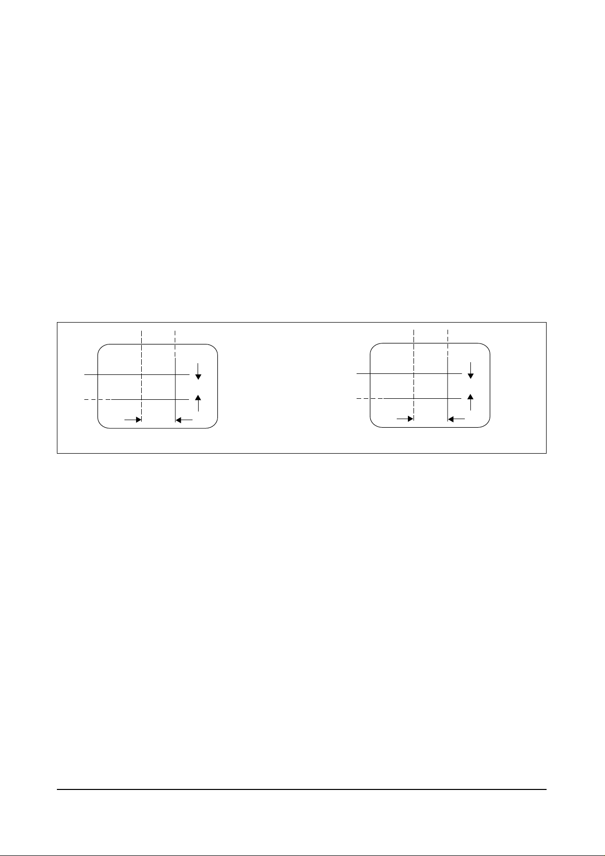
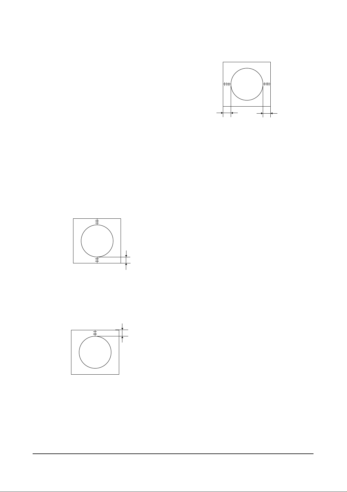
4-3-11 Geometry Adjustment
SC →VS→VSL→HS
1. Input a lion head pattern (in the PAL channel).
2. Set the SC (S-Correction) as follows : 9 (21”),
9 (20”), 0 (14”) and VA 40 so that the lion
head circle becomes oval.
3. Adjust with VSL (Vertical-Slope) so that the
bottom margin of the picture is 4.
Fig. 4-7
4. Adjust with VS (Vertical shift) so that the top
margin of the picture is 4.
Fig. 4-8
5. Adjust with HS (Horizontal Shift) so that the
lion-head pattern and CRT centers are aligned.
Fig. 4-9
6. Adjust HS (using the width coil) so that the
left and right margins of the picture are 5.
Alignment and Adjustments
4-8 Samsung Electronics
4
5
5
4
PSR
NSR
2
5
No Code No Description;Specification Q’ty Remark
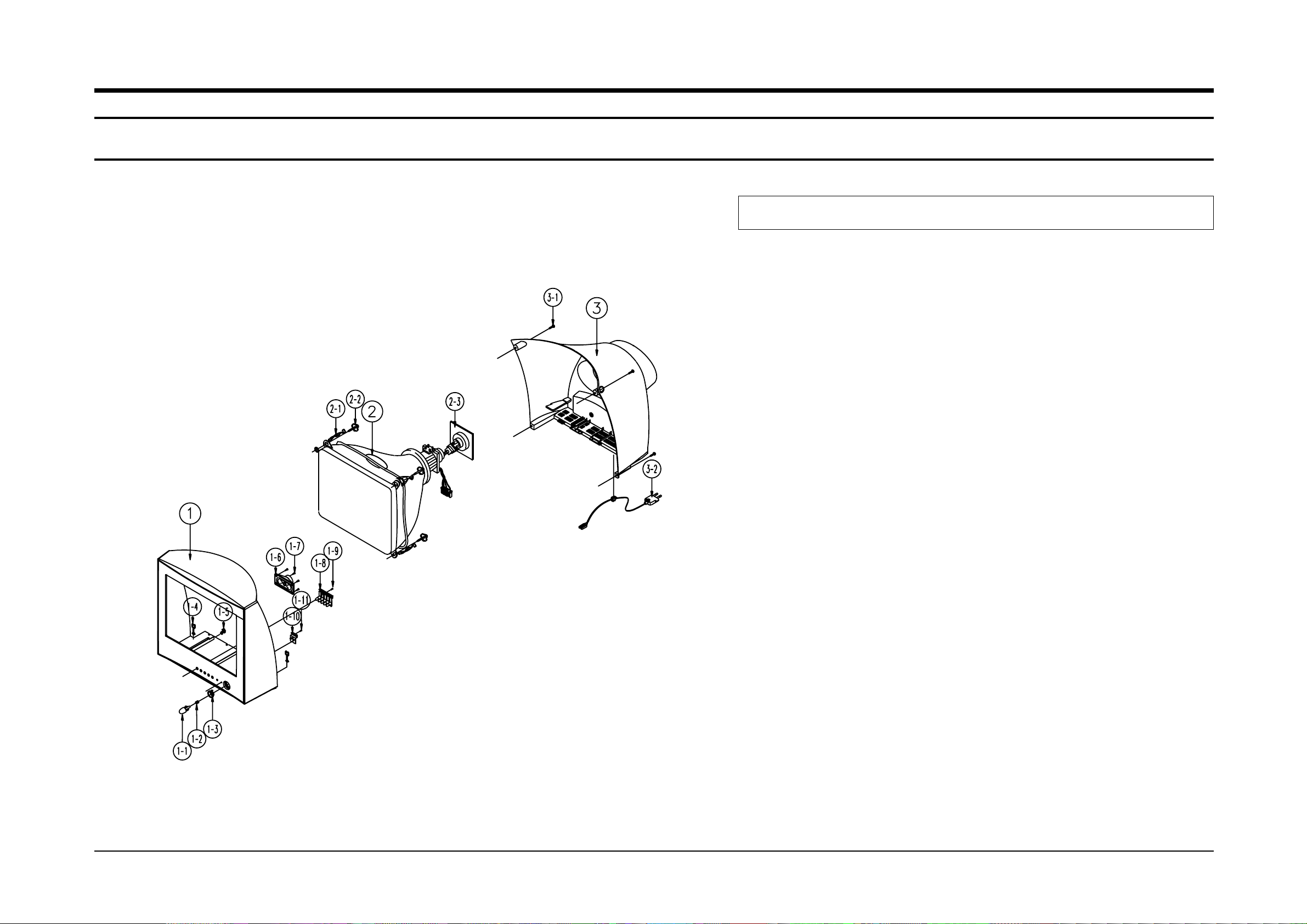
6. Exploded View & Parts List
6-1 CS15K2X/BWT
Exploded View & Parts List
Samsung Electronics 6-1
1 AA91-00649C ASSY CABINET FRONT;,15K2,(SPK)SV012P MPP 1
AA64-01691D CABINET FRONT;15K2,SV012P MPP,HIPS,HB,G7 1
1-1 AA64-01693B KNOB POWER;15K2,ABS,G3676,SV104M+W971,HB 1
1-2 AA61-60003J SPRING-CS;-,SUS304,0.5,OD6,H12,N7,-,-,- 1
1-3 AA64-01697B DECORATION-POWER;15K2,PC,SEMI-VIOLET 1
1-4 AA65-30105A CLAMP-WIRE;NYLON 66,V2,NTR,15MM,ALL MODE 1
1-5 AA61-40113A STOPPER-PCB;501H,HIPS,-,-,HB,NTR,- 1
1-6 AA96-00652A ASSY SPEAKER;-,16OHM,3W,3001-001211,200M 1
1-7 6003-001022 SCREW-TAPTITE;RH,+,B,M3,L12,ZPC(BLK),SWR 4 SPK+CF
1-8 AA64-01696B KNOB CONTROL;15K2,ABS,G3676,SV104M+W971, 1
1-9 6003-001026 SCREW-TAPTITE;RH,+,B,M4,L15,ZPC(BLK),SWR 1 KC+CF
1-10 AA64-01694B WINDOW REMOCON;15K2,ACRYL,CLR 1
1-11 6003-001026 SCREW-TAPTITE;RH,+,B,M4,L15,ZPC(BLK),SWR 1 WIN+CF
2 AA03-00146A CRT COLOR;-,A36QDT351X,+380mG,15inch,90, 1
2-1 AA65-30107A CLAMP-D,COIL;NYLON 66,V2,NTR,-,20~22 INC 2
2-2 AA60-10050R SCREW-ASSY;-,SWRCH18A,M5,L31.5,HH,+,WC,- 4 CRT
2-3 3704-001105 SOCKET-CRT;11P,20PI,26.5PI,NI,- 1
3 AA64-01692C CABINET BACK;15K2,HIPS,V2,BLK 1
3-1 AA60-10050T SCREW-TAPPING;-,SWRCH18A,M4,L20,RH,+,2S, 4 CB+CF
3-2 AA96-20109B ASSY-POWER,CORD;-,CP2/NO(4.0),H/C250,KKP 1
Exploded View & Parts List
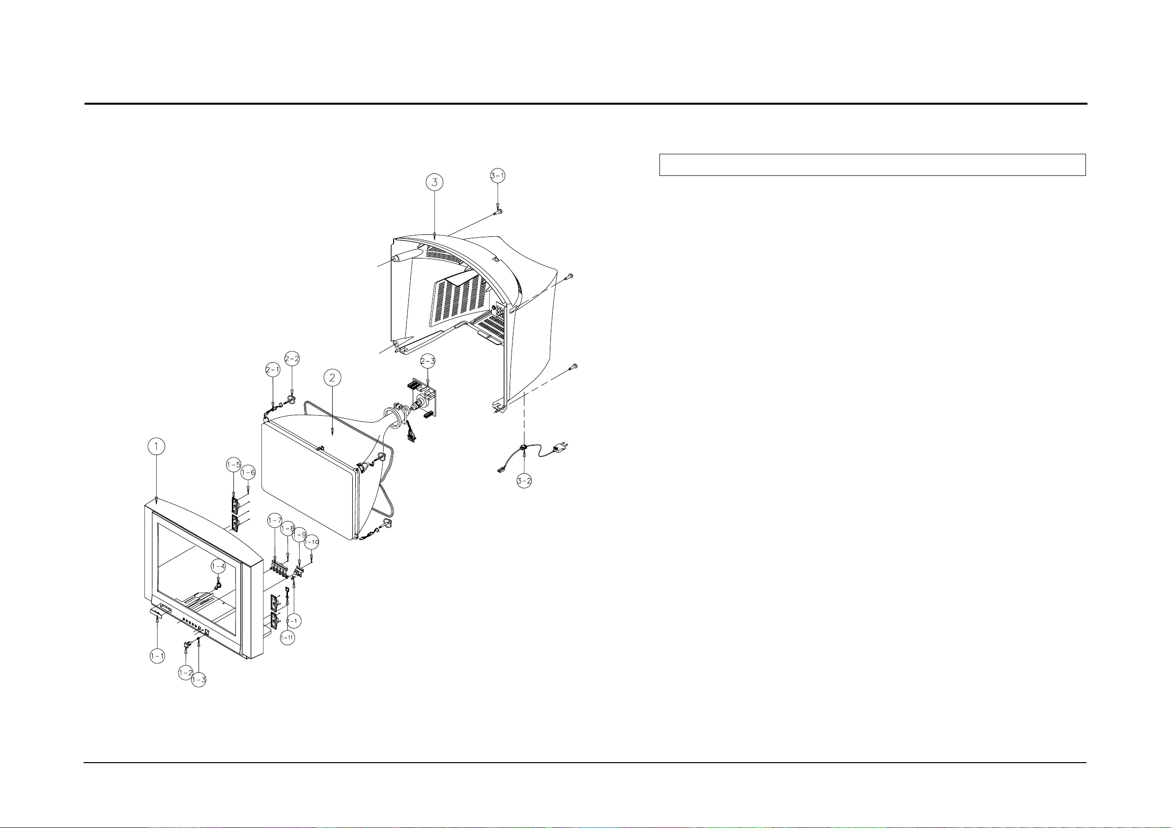
6-2 Samsung Electronics
No Code No Description;Specification Q’ty Remark
6-2 CS15K8WX/BWT
1 AA91-00619B ASSY CABINET FRONT;,15K8 CIS,(SPK)S012P+ 1
AA64-01730F CABINET FRONT;15K8,S012P+B115P CIS S/T,H 1
1-1 INLAY-COVER
1-2 AA64-01371C KNOB POWER;15K8,ABS,G3676,SV012P+W971,HB 1
1-3 AA61-60003J SPRING-CS;-,SUS304,0.5,OD6,H12,N7,-,-,- 1
1-4 AA61-40113A STOPPER-PCB;501H,HIPS,-,-,HB,NTR,- 1
1-5 AA96-10137B ASSY-SPEAKER;-,8OHM,3W,3001-001020,AA39- 4
1-6 6003-001019 SCREW-TAPTITE;RH,+,B,M4,L12,ZPC(BLK),SWR 8 SPK+CF
1-7 AA64-01370C KNOB CONTROL;15K8,ABS,G3676,SV012P+W971, 1
1-8 6003-001019 SCREW-TAPTITE;RH,+,B,M4,L12,ZPC(BLK),SWR 1 KC+CF
1-9 AA64-00816B WINDOW REMOCON;-,21A8,-,PC,V0,VIOLET,- 1
1-10 6003-001019 SCREW-TAPTITE;RH,+,B,M4,L12,ZPC(BLK),SWR 1 WIN+CF
1-11 AA65-00011C CLAMP-WIRE;ALL MODEL,NYLON 66,V2,NTR,25M 1
1-12 AA64-00818B INDICATOR LED;-,21A8,-,ACRYL,-,CLR,- 1
2 AA03-00146A CRT COLOR;-,A36QDT351X,+380mG,15inch,90, 1
2-1 AA65-30107A CLAMP-D,COIL;NYLON 66,V2,NTR,-,20~22 INC 2
2-2 AA60-10050R SCREW-ASSY;-,SWRCH18A,M5,L31.5,HH,+,WC,- 4 CRT+CF
2-3 3704-001105 SOCKET-CRT;11P,20PI,26.5PI,NI,- 1
3 AA64-01731C CABINET BACK;15K8,HIPS,V2,BLK 1
3-1 AA60-10050T SCREW-TAPPING;-,SWRCH18A,M4,L20,RH,+,2S, 4 CB+CF
3-2 AA96-20109B ASSY-POWER,CORD;-,CP2/NO(4.0),H/C250,KKP 1
2
Exploded View & Parts List
Samsung Electronics 6-3
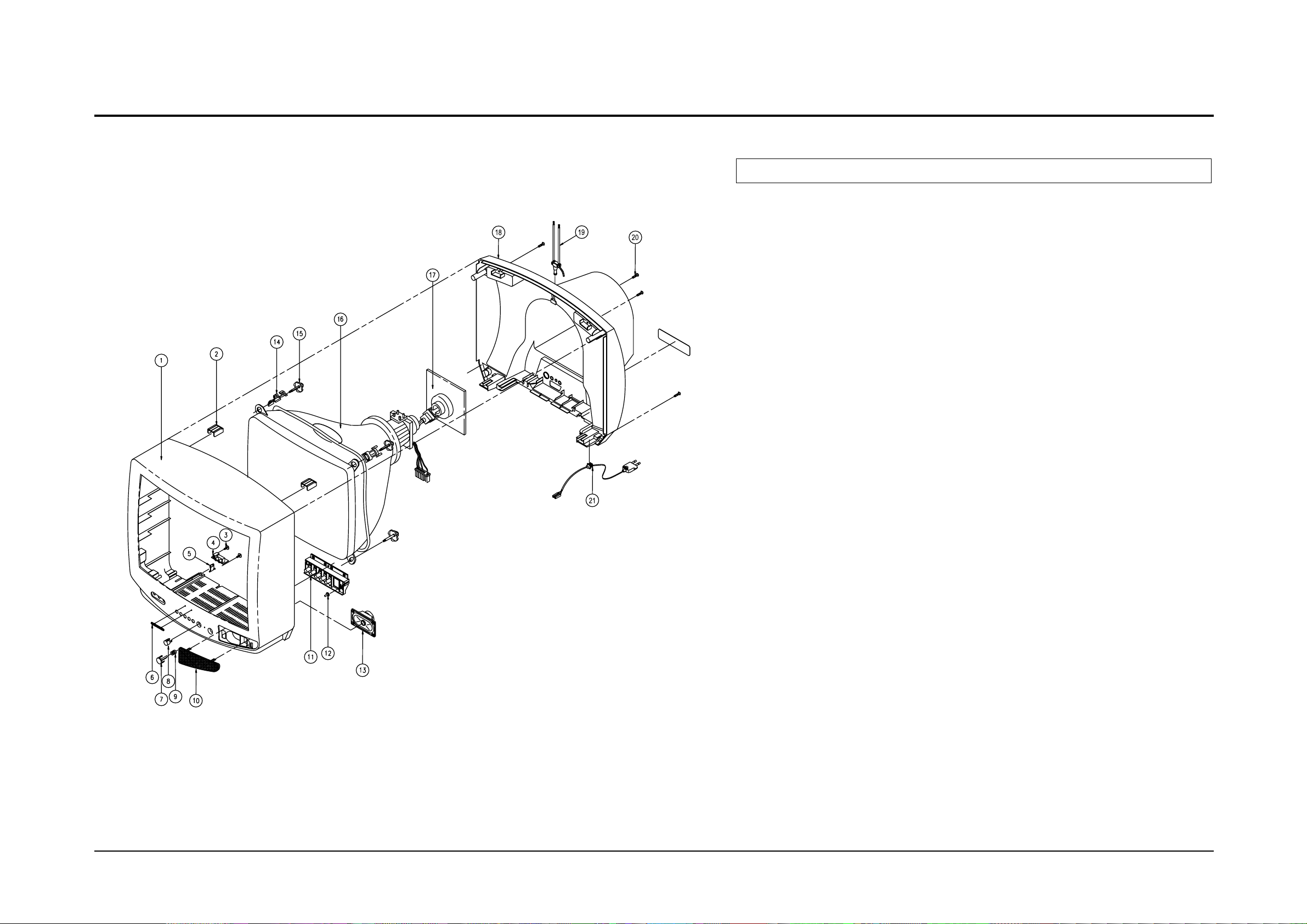
No Code No Description;Specification Q’ty Remark
6-3 CS2073S/BWT
1 AA91-00691B ASSY CABINET FRONT;DP,5073,(SPK) BK708P 1
AA64-00233C CABINET-FRONT;-,5073,BK708P MLN,HIPS,HB, 1
2 AA61-40010A BOSS-WING;-,HIPS,-,-,-,NTR,HB 2
3 6006-001095 SCREW-ASS’Y TAPT;WP,BH,+,M4,L12,ZPC(YEL) 2 PA+CF
4 AA95-01042B ASSY-PCB,A/V FRONT;DP,2139,KS1A,AA95-900 1
5 AA61-40007A STOPPER-PCB;5038.5368,HIPS HB,-,-,-,NTR, 1
6 AA64-70127F BADGE-BRAND;AL,SAMSUNG,SILVER,L40,R800,N 1
7 AA64-10131A KNOB-POWER;-,5073,-,ABS,HB,BLK 1
8 AA61-60003J SPRING-CS;-,SUS304,0.5,OD6,H12,N7,-,-,- 1
9 AA64-40044B WINDOW-REMOCON;-,5073,-,PC,V0,VIOLET,- 1
10 AA63-50095A GRILLE-WOOFER;-,5073,PA110 PI0.6,SECC,T0 1
11 AA64-10039A KNOB-CONTROL;-,5073,-,ABS,HB,BLK 1
12 AA64-40182A INDICATOR-LED;-,5073,-,ACRYL,-,-,- 1
13 AA96-10140A ASSY-SPEAKER;-,16ohm3W,00003,AA320501C,R 1
14 AA65-30107A CLAMP-D,COIL;NYLON 66,V2,NTR,-,20~22 INC 4
15 AA60-10050R SCREW-ASSY;-,SWRCH18A,M5,L31.5,HH,+,WC,- 4 CRT+CF
16 AA03-10029W CRT-COLOR;-,A48KRD82X(H),+380mG,20,90de 1
17 3704-001105 SOCKET-CRT;11P,20PI,26.5PI,NI,- 1
18 AA64-30375D CABINET-BACK;-,5038.73,-,HIPS,V2,BLK,-,- 1
19 AA42-00003A ANT ROD;-,3S,720mm,ABS,UL/CSA,- 1
20 6003-001026 SCREW-TAPTITE;RH,+,B,M4,L15,ZPC(BLK),SWR 4 CB+CF
21 AA96-20109B ASSY-POWER,CORD;-,CP2/NO(4.0),H/C250,KKP 1
 Loading...