

Samsung CS21A9W2QS/MUR Service Manual
COLOR TELEVISION RECEIVER
Chassis : KS1C(P)
Model : CS21A9W2QS/MUR
COLOR TELEVISION RECEIVER CONTENTS
Precautions
Reference Information
Specifications
Alignment and Adjustments
Troubleshooting
Exploded Views and Parts List
Electrical Parts List
Block Diagrams
Wiring Diagram
Schematic Diagrams
1.
2.
3.
4.
5.
6.
7.
8.
9.
10.
ELECTRONICS
© Samsung Electronics Co., Ltd. Jul. 2003
Printed in Korea
AA82-00868A
This Service Manual is a property of Samsung Electronics Co.,Ltd.
Any unauthorized use of Manual can be punished under applicable
International and/or domestic law.
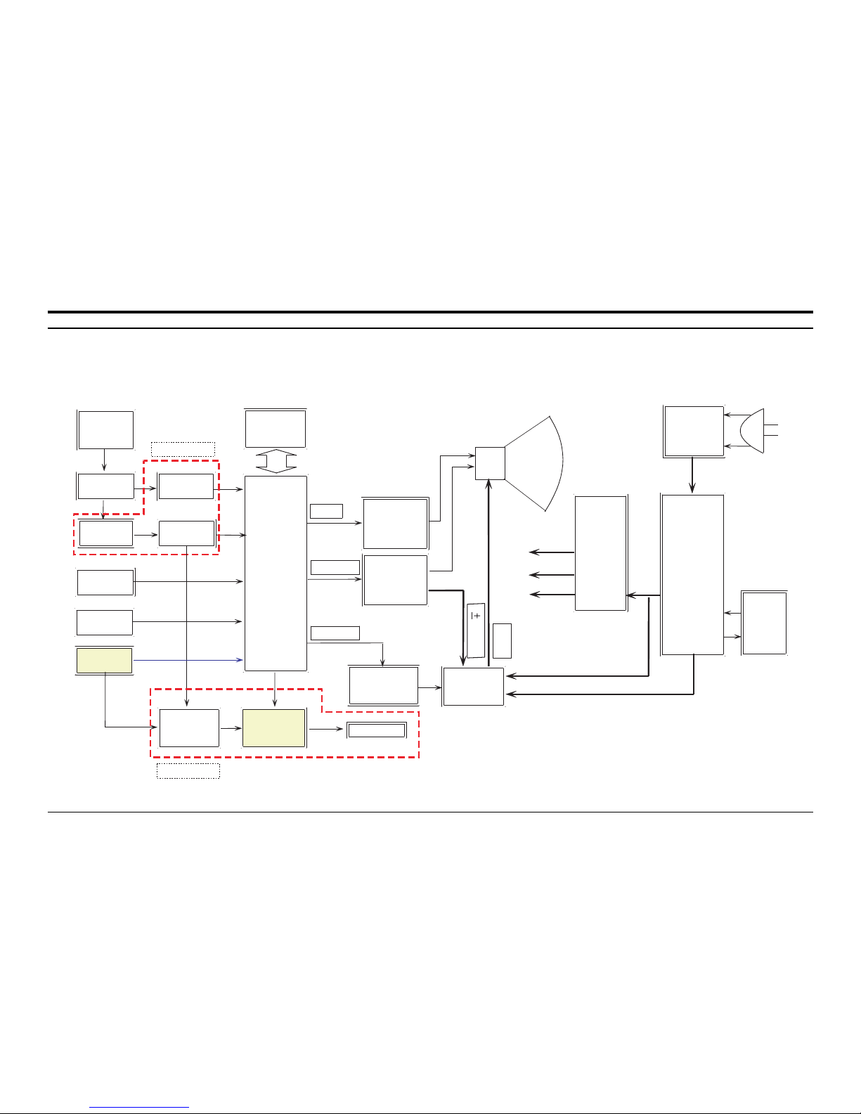
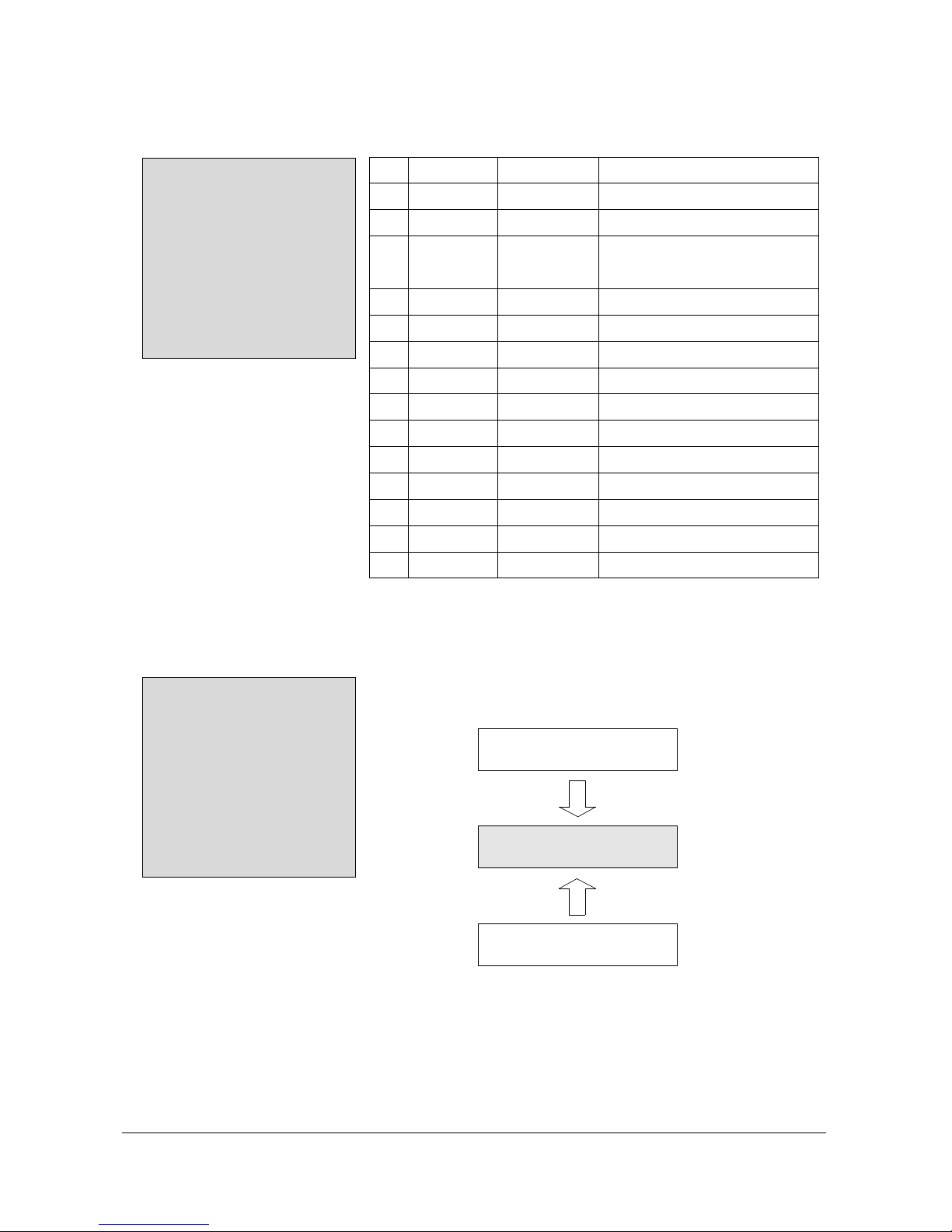
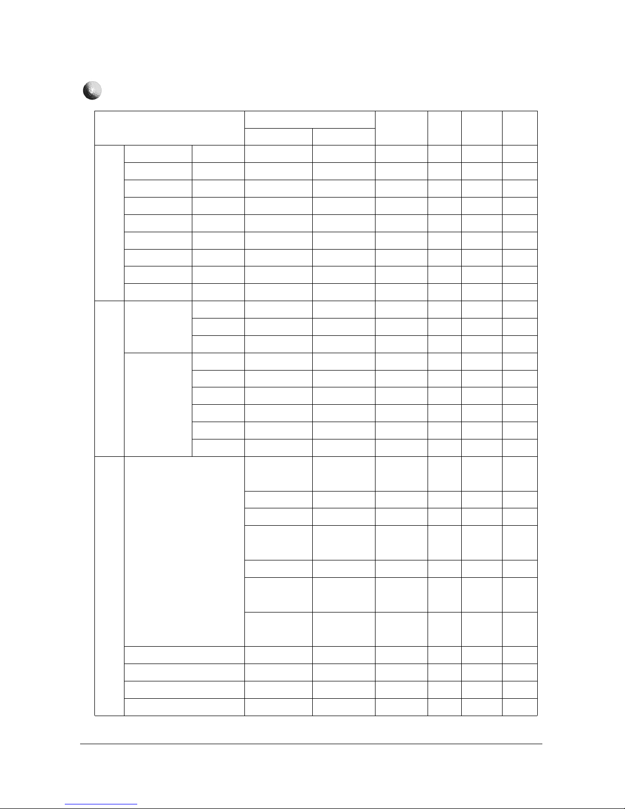
8. Block Diagrams
Samsung Electronics
Block Diagrams
8-1
TUNER
A/V
IN
DVD
IN
U. O. C
PLUS
EEPROM
VERT ICAL
AMP
H- OUT T R
AUDI O
AMP
10W X2CH
FBT
S/ W
TRANS
AC / DC
Converter
SMPS
CONT
ROLER
KA7632
CRT 21" FLAT
SPEAKER
VI DEO
AMP
130V
13V
To FBT B+
To Sound AMP B+
UOC
UOC
RGB
V-Dri ve
H-Dri ve
Pr e-
AMP
VIF SAW
+S/W
8V
5V
3. 3V
TUNER
JACK
RCA
SIFSAW
+S/W
SIF
IC
<OPTION>
MSP
<OPTION>
180V
16. 5V
PCB : 245 X 245

Alignment and Adjustments
Samsung Electronics 4-1
4. Alignment and Adjustments
4-1 General Alignment Instructions
1. Usually, a color TV-VCR needs only slight
touch-up adjustment upon installation. Check
the basic characteristics such as height,
horizontal and vertical sync and focus.
2. Observe the picture for good black and white
details. There should be objectionable color
shading; if color shading is present,
demagnetize, perform purity and convergence
adjustments described below.
3. Use the specified test equipment or its
equivalent.
4. Correct impedance matching is essential.
5. Avoid overload. Excessive signal from a
sweep generator might overload the front-end
of the TV. When inserting signal markers, do
not allow the marker generator to distort test
results.
6. Connect the TV only to an AC power source
with voltage and frequency as specified on the
backcover nameplate.
7. Do not attempt to connect or disconnect any
wires while the TV is turned on. Make sure
that the power cord is disconnected before
replacing any parts.
8. To protect against shock hazard, use an
isolation transformer.
4-2 Automatic Degaussing
A degaussing coil is mounted around the
picture tube, so that external degaussing after
moving the TV should be unnecessary. But
the receiver must be properly degaussed upon
installation.
The degaussing coil operates for about 1
second after the power is switched ON. If the
set is moved or turned in a different direction,
the power should be OFF for at least 10
minutes.
If the chassis or parts of the cabinet become
magnetized, poor color purity will result. If
this happens, use an external degaussing coil.
Slowly move the degaussing coil around the
faceplate of the picture tube and the sides and
front of the receiver. Slowly withdraw the coil
to a distance of about 6 feet before turning
power OFF.
If color shading persists, perform the
following Color purity and Convergence
adjustments.
4-3 High Voltage Check
CAUTION : There is no high voltage adjustment
on this chassis. The B+ power supply should be
+135 volts (with full color- bar input and normal
picture level).
1. Connect a digital voltmeter to the second
anode of the picture tube.
2. Turn on the TV. Set the Brightness and
Contrast controls to minimum (zero beam
current).
3. Adjust the Brightness and contrast controls to
both extremes. Ensure that the high voltage
does not exceed 30 KV under any conditions.
Alignment and Adjustments
4-2 Samsung Electronics
4-4 FOCUS Adjustment
1. Iput a black and white signal.
2. Adjust the tuning control for the clearest picture.
3. Adjust the FOCUS control for well defined scanning lines in the center area of the screen.
4-5 Factory Adjustment
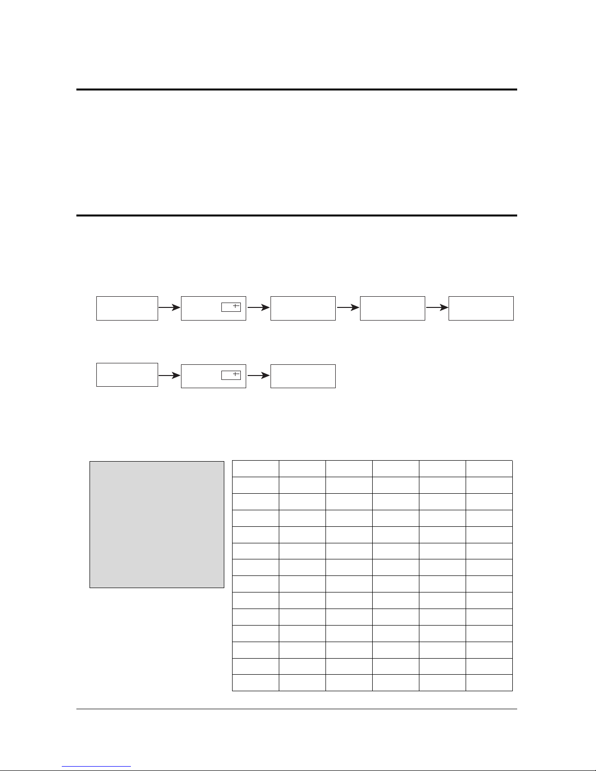
1. To enter the “Service Mode”, Press the remote-control keys in this sequence :
- If you do not have Factory remote-control
- If you have Factory remote-control
PICTURE OFF PICTURE ON
DISPLAY
()
MENU
MUTE
PICTURE ON
DISPLAY
()
FACTORY
4-5-1 Service Mode
4-5-2 Factoy Mode OSD
ADJUST
OPTION 52 2A 48
G2-ADJUST
RESET
SPM-836EAN 2002/XX/XX
AGC
SCT
SBT
BLR
BLB
RG
GG
BG
VSL
VS
VA
HS
SC
CDL
33
13
9
31
27
32
25
31
19
38
40
30
24
9
STT
AKB
PDL
NDL
PSR
NSR
VOL
LCO
TXP
MVOL
FMWS
AGCS
OMD
SCL
7
0
15
10
15
10
10
0
9
10
0
1
26
1
PWL
AGN
PEK
ACL
FCO
SCBT
SSP
PSNS
DPSR
DNSR
DSBT
DCDL
DBLR
DBLB
12
1
2
0
0
45
15
1
15
10
7
9
31
27
4-5-2(A) ADJUST
Alignment and Adjustments
Samsung Electronics 4-3
OSD
AGC
SCT
SBT
BLR
BLB
RG
GG
BG
VSL
VS
VA
HS
SC
CDL
STT
AKB
PDL
NDL
PSR
NSR
VOL
LCO
TXP
MVOL
FMWS
AGCS
OMD
SCL
PWL
AGN
PEK
ACL
FCO
SCBT
SSP
Range
0 ~ 63
0 ~ 23
0 ~ 23
0 ~ 63
0 ~ 63
0 ~ 63
0 ~ 63
0 ~ 63
0 ~ 63
0 ~ 63
0 ~ 63
0 ~ 63
0 ~ 63
0 ~ 15
0 ~ 7
0 ~ 1
0 ~ 15
0 ~ 15
0 ~ 23
0 ~ 23
0 ~ 63
0 ~ 1
0 ~ 15
0 ~ 50
0 ~ 1
0 ~ 3
0 ~ 63
0 ~ 3
0 ~ 15
0 ~ 1
0 ~ 3
0 ~ 1
0 ~ 1
0 ~ 63
0 ~ 23
Register
1Eh(D5-D0)
1Dh
1Bh
14h(D5-D0)
15h(D5-D0)
16h(D5-D0)
17h(D5-D0)
18h(D5-D0)
0Fh(D5-D0)
12h(D5-D0)
10h(D5-D0)
09h(D5-D0)
0Fh(D5-D0)
2Ah(D3-D0)
08h
2Ah(D4)
1Ah(D3-D0)
1Ah(D3-D0)
1Ch
1Ch
1Fh
27h(D7-D5)
87F2h(D5-D0)
Oh(D15-D0)
29h(D5)
28h(D2-D1)
05h(D5-D0)
04h(D5-D4)
04h(D3-D0)
29h(D7)
19h(D7-D6)
20h(D1)
21h(D0)
1Bh
19h(D5-D0)
Initial Value
33
13
9
31
27
32
25
31
19
38
40
30
24
9
7
0
15
10
15
10
10
0
9
10
0
1
26
1
12
1
2
0
0
45
20
Remark
RF AGC
Sub contrast(high light adjustment)
Sub brightness(low light adjustment)
Black level offset R(low light R adjustment)
Black level offset B(low light B adjustment)
White point R(high light R adjustment)
White point G(high light 25 fixed)
White point B(high light B adjustment)
Vertical slope
Vertical shift
Vertical amplitude
Horizontal shift
S-correction
Cathode drive level
Sub tint(NTSC only)
Black current stabilization
PAL Y-delay adjustment
NTSC Y-delay adjustment
PAL sub color gain adjustment
NTSC sub color gain adjustment
Initial vol adjustment
PLL demodulator frequency adjust( 0 : set )
TTX horizontal shift adjustment(Micom Memory Part)
Melody initial vol adjustment(MSP34XX)
Narrow-band sound PLL window selection
IF AGC speed
Off-set IF demodulator
Soft clipping level
Peak white limiting
FM demodulator gain
Peaking center frequency
Automatic color limiting
Forced color limiting
Screen brightness(different from INCH)
Sub Sharpness gain adjustment
Alignment and Adjustments
4-4 Samsung Electronics
OSD
PSNS
DPSR
DNSR
DSBT
DCDL
DBLR
DBLB
Range
0 ~ 1
0 ~ 23
0 ~ 23
0 ~ 23
0 ~ 15
0 ~ 63
0 ~ 63
Register
21h(D2)
1Ch
1Ch
1Bh
2Ah(D3-D5)
14h(D5-D0)
15h(D15-D0)
Initial Value
1
15
10
7
9
31
27
Remark
Ident sensitivity PAL/NTSC decoder
DVD PAL sub color gain adjustment
DVD NTSC sub color gain adjustment
DVD Sub brightness(low light adjustment)
DVD Cathode drive level
DVD Black level offset R(low light R adjustment)
DVD Black level offset B(low light B adjustment)
Alignment and Adjustments
Samsung Electronics 4-5
ADJUST
OPTION 52 2A 48
G2-ADJUST
RESET
SPM-834EAN 2002/XX/XX
Item
LNA
SYSTEM
AUDIO
JACK
ZOOM
AUTO POWER
SBL
2nd SIF
HOTEL MODE
BL STRETCH
HIGH DEVIA
HELP MENU
LANGUAGE
V-GUARD
No
1
2
3
4
5
6
7
8
9
10
11
12
13
14
Initial value
OFF
CS
MONO
RCA + DVD
NOR/ZOOM/16:9
ON
OFF
ON
OFF
ON
OFF
ON
EAST ASIA
OFF
Remark
CIS : ON
CS ↔ CB ↔ CD
MONO ↔ MONO/BILI↔L-STEREO
↔L-STEREO/BILI↔STEREO↔NICAM
RCA ↔ SCART ↔ RCA+DVD
NOR/ZOOM/16:9 ↔ NOR/ZOOM
MUST ON
OFF(MUST OFF)
ON ↔ OFF
ON ↔ OFF(OPTION)
ON ↔ OFF(EUROPE OFF)
OFF(MUST OFF)
ON ↔ OFF(EUROPE OFF)
EAST ASIA ↔ CHINA
OFF(MUST OFF)
4-5-2(B) OPTION
ADJUST
OPTION 52 2A 48
G2-ADJUST
RESET
SPM-836EAN 2002/XX/XX
4-5-2(C) G2-ADJUST
☞ Entering G2-Adjust Mode Screen Adjust : Displyed As “NG”.
→ Turn SCREEN VR OF FBT, Adjust Value Become To Be “OK”.
Screen Adjust : N.G
Screen Adjust : O.K
Screen Adjust : N.G
Alignment and Adjustments
4-6 Samsung Electronics
4-6 MICOM
4-6-1 UOC IC 1-CHIP Part Pin Port Function
Pin No
12
13
14
15
16
17
18
19
20
21
22
23
24
25
26
27
28
29
30
31
32
Pin No
53
52
51
50
49
48
47
46
45
44
43
42
41
40
39
38
37
36
35
34
33
FUNCTION
Analog GND of TV
Secam PLL decoupling
2nd supply voltage(8V)
Supply voltage of digital circuit
Phase-2 filter
Phase-1 filter
GND 3 for TV
Bandgap decoupling
Automatic Volume Leveling(90’ ver)
Vertical drive B out
Vertical drive A out
IF input 1
IF input 2
Reference current input
Vertical sawtooth cap
Tuner AGC out
Audio deemphasis
Decoupling sound demodulator
GND 2 for TV
Narrow band PLL filter
Sound IF input/ AM output
FUNCTION
B out
G out
R out
Black current in/V-guard in
Beam current limiter in
B-in/Pb-in
G-in/Y-in
R-in/Pr-in
F/B in
Audio output(volume controlled)
GND
EXT CVBS in
GND for TV
Internal CVBS input
Main supply voltage TV(8V)
IF Video out
IF-PLL loop filter
EHT/over voltage protection in
External audio out/AM output
Flyback in/sandcastle out
Horizontal out
MICOM
PART
1-CHIP
UOC-IC
PART
1
.
.
.
11
64
.
.
.
54
12
.
.
.
.
.
.
.
.
32
53
.
.
.
.
.
.
.
.
33
Alignment and Adjustments
Samsung Electronics 4-7
4-6-2 UOC MICOM Part Pin Port Function
Pin No
1
2
3
4
5
6
7
8
9
10
11
54
55
56
57
58
59
60
61
62
63
64
INITIAL
LOW
SERIAL H
SERIAL H
LOW
LOW & HIGH
HIGH
HIGH
HIGH
HIGH
GND
HIGH
LOW
HIGH
HIGH
ASSIGNMENT
ACTIVE HIGH
E
2
PROM/UOC/TUNER/MSP34XX SCL LINE
E2PROM/UOC/TUNER/MSP34XX SCL LINE
ACTIVE HIGH
STD-BY:LOW, NORMAL OPERATION:HIGH, BUS STOP(STOP:LOW)
MENU, VOL-DOWN, VOL-UP CONTROL
CH-DOWN, CH-UP, TV/VIDEO CONTROL
TV MODE : OV AV MODE:HIGH(3.3V)
4.5Mhz : LOW 5.5-6.5Mhz : HIGH
Digital GND for MICOM
TV MODE : OV AV MODE : HIGH(3.3V)
PAL : HIGH NTSC : LOW L : LOW L’ ; HIGH
Analog supply of TTX and Digital supply of TV(3.3V)
OTP Programming voltage
Digital supply to core(3.3V)
Oscillator GND supply
XTAL oscillator input
XTAL oscillator output
POWER ON : 25ms HIGN -> LOW
Digital supply to periphery(3.3V)
PRE AMP Signal input
Select bilingual
TV out for inrush voltage : AUOT TV ON
FUNCTION
POWER
SCL
SDA
MUTE
STD-BY & BUS-STOP
KEY-1
KEY-2
SC1-ID & CHINA SOUND
& SAW S/W
GND
TV/VIDEO S/W
NT/PAL & AW-S/W
& L/L’-S/W
VDDA 3.3V
VPE
VDDC 3.3
OSCGND
XTAL IN
XTAL OUT
RESET
VDDP
SIGNAL IN
BILINGUAL
HOLD
Alignment and Adjustments
4-8 Samsung Electronics
Request
●
●
●
●
●
Requisite
●
●
●
●
●
●
●
●
●
●
●
●
Option
●
●
●
●
●
●
●
●
●
Remarks
Scart Option
X
X
0
0
0
0
0
PAPILLON KS1C
0
X
X
100
1H
X
0
0
21F
1
X
1
1
1
X
1
Option(1)
1
0
X
0
0
0
0
0
0
0
0
Option
Before KS2A
0
X
X
100
0
X
0
0
21F/25F/25”~29”
1
X
1
1
2
X
1
Option(2)
1
Cope With or
Without
Double Screen
Turbo Sound
Auto Volume
Leveler
Sound Mode
Sound Tone
Control
Melody Sound
On/Off
0
0
0
Option
P
i
c
t
u
r
e
J
a
c
k
F
u
n
c
t
i
o
n
Broadcasting
System
Scan System
Program ch’
Comb Filter
VM Circuit
Auto Kinetic Bias
Noise Reduction
CRT
The-Front
The-Side
Back
PIP
Sleep timer
Plug & Play
TTXT
PAL MULTI
EURO MULTI
Progressive
100/181/200
AV-In
S-VHS
H-Phone
RF Jack
AV-In
S-VHS
DVD(Y,Pb,Pr)
Scart Jack
M-out
On/Off timer, Clock
Section
PAL
SPECIFICATIONS(MRT)
Alignment and Adjustments
Samsung Electronics 4-9
SPECIFICATIONS(MRT)
RequestRequisite
●
●
●
●
●
●
●
Option
●
●
●
Remarks
PAPILLON KS1C
Multi
0
X
0
0
X
0
0
2
Option
10W x 2CH
Before KS2A
Multi
0
X
0
0
X
0
0
2
Option
10W x 2CH
F
u
n
c
t
i
o
n
S
o
u
n
d
OSD Language
Auto Power Off
Previous Channel
Blue Screen
Demo Mode
Game
Sound
A2/Nicam
Main-R/L
Out(TTL)
Out(TTL)
Surround
Speaker Quantity
Speaker Type
RMS/CH
RMS/CH
Section
PAL
 Loading...