

Samsung CM-350 Service manual

DVD-VCR COMBINATION
CHT-350
◆ Main Unit ; DVD-CM350
◆ Speakers ; SP-350
SERVICE
1. Precautions
2. Alignment and Adjustment
3. Exploded Views and Parts List
4. Electrical Parts List
5. Block Diagram
6. Schematic Diagrams
Manual
DVD-VCR COMBINATION CONTENTS
SERVICE MANUAL CHT-350
OPEN/CLOSE
CHANNEL DVD VCR FM/AM INPUT
EJECT
PHONES
REC S.MODE S.EFFECT
VOL
ELECTRONICS
© Samsung Electronics Co., Ltd. FEB. 2003
Printed in Korea
AK82-00320A
If you want to know additional information which is not including on this Service Manual, please refer to the
Training Manual of CHT-350 (AK82-00323A).
IMPORTANT SERVICE GUIDE
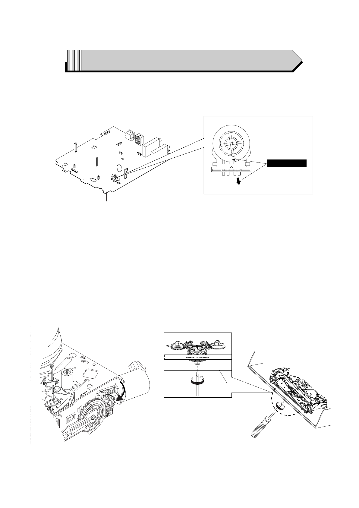
◆ MODE SWITCH (PROGRAM SWITCH) ASSEMBLY POINT
1) When installing the ass’y deck on the Main PCB, be sure to align the assembly point of mode switch.
ASSEMBLY POINT
VCR MAIN PCB
Fig. 1
◆ HOW TO EJECT THE CASSETTE TAPE
(If the unit does not operate on condition that tape is inserted into housing ass’y)
1) Turn the Gear Worm Πclockwise in the direction of arrow with screw driver. (See Fig. 2)
(Other method ; Remove the screw of Motor Load Ass’y, Separate the Motor Load Ass’y)
2) When Slider S, T are approached in the position of unloading, rotate holder Clutch counterclockwise after inserting screw driver in the
hole of frame’s bottom in order to wind the unwiunded tape. (Refer to Fig. 3)
(If you rotate Gear Worm Πcontinuously when tape is in state of unwinding, you may cause a tape contamination by grease and
tape damage. Be sure to wind the unwiunded tape in the state of set horizontally.)
3) Rotate Gear Worm Πclockwise using screw driver again up to the state of eject mode and then pick out the tape. (Refer to Fig. 2)
Fig. 2 Fig. 3
ΠGEAR WORM
FRAME
Samsung Electronics 1-1
1. Precautions
1-1 Safety Precautions
1. Be sure that all of the built-in protective devices are
replaced. Restore any missing protective shields.
2. When reinstalling the chassis and its assemblies, be
sure to restore all pretective devices, including :
control knobs and compartment covers.
3. Make sure that there are no cabinet openings
through which people--particularly children -might insert fingers and contact dangerous
voltages. Such openings include the spacing
between the picture tube and the cabinet mask,
excessively wide cabinet ventilation slots, and
improperly fitted back covers.
If the measured resistance is less than 1.0 megohm
or greater than 5.2 megohms, an abnormality exists
that must be corrected before the unit is returned
to the customer.
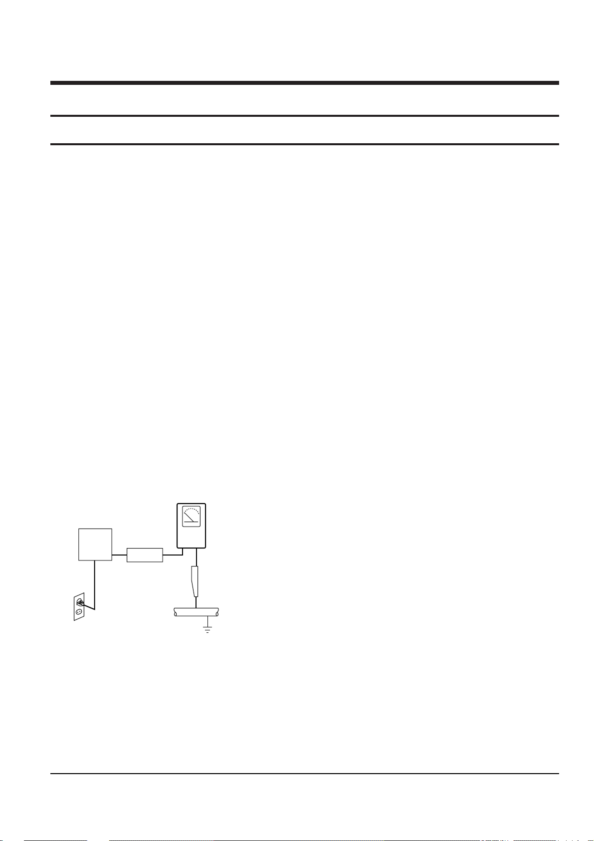
4. Leakage Current Hot Check (See Fig. 1-1) :
Warning : Do not use an isolation transformer
during this test. Use a leakage current tester or a
metering system that complies with American
National Standards Institute (ANSI C101.1,
Leakage Current for Appliances), and Underwriters
Laboratories (UL Publication UL1410, 59.7).
Fig. 1-1 AC Leakage Test
5. With the unit completely reassembled, plug the AC
line cord directly the power outlet. With the unit’s
AC switch first in the ON position and then OFF,
measure the current between a known erath
ground (metal water pipe, conduit, etc.) and all
exposed metal parts, including : antennas, handle
brackets, metal cabinets, screwheads and control
shafts. The current measured should not exceed
0.5 milliamp. Reverse the power-plug prongs in the
AC outlet and repeat the test.
6. Antenna Cold Check :
With the unit’s AC plug disconnected from the
AC source, connect an electrical jumper across the
two AC prongs. Connect one lead of the ohmmeter
to an AC prong.
Connect the other lead to the coaxial connector.
7. Some semiconductor (“solid state”) devices are
easily damaged by static electricity.
Such components are called Electrostatically
Sensitive Devices (ESDs); examples include
integrated circuits and some field-effect transistors.
The following techniques will reduce the
occurrence of component damage caused by static
electricity.
8. Immediately before handling sny semiconductor
components or assemblies, drain the electrostatic
charge from your body by touching a known
earth ground. Alternatively, wear a discharging
Wrist-strap device. (Be sure to remove it prior to
applying power--this is an electric shock
precaution.)
9. Design Alteration Warning :
Never alter or add to the mechanical or electrical
design of this unit. Example : Do not add
auxiliary audio or video connectors.
Such alterations might create a safety hazard.
Also, any design changes or additions will void
the manufacturer’s warranty.
10. Never defeat any of the B+ voltage interlocks.
Do not apply AC power to the unit (or any of its
assemblies) unless all solid-state heat sinks are
correctly installed.
DEVICE
UNDER
TEST
(READING SHOULD
NOT BE ABOVE
0.5mA)
LEAKAGE
CURRENT
TESTER
EARTH
GROUND
TEST ALL
EXPOSED METER
SURFACES
ALSO TEST WITH
PLUG REVERSED
(USING AC ADAPTER
PLUG AS REQUIRED)
2-WIRE CORD

Precautions
1-2 Samsung Electronics
11. Always connect a test instrument’s ground lead to
the instrument chassis ground before connecting
the positive lead; always remove the instrument’s
ground lead last.
12. Observe the original lead dress, especially near
the following areas : Antenna wiring, sharp
edges, and especially the AC and high voltage
power supplies. Always inspect for pinched, outof-place, or frayed wiring. Do not change the
spacing between components and the printed
circuit board. Check the AC power cord for
damage. Make sure that leads and components
do not touch thermally hot parts.
13. Product Safety Notice :
Some electrical and mechanical parts have special
safety-related characteristics which might not be
obvious from visual inspection. These safety
features and the protection they give might be
lost if the replacement component differs from the
original--even if the replacement is rated for
higher voltage, wattage, etc.
Components that are critical for safety are
indicated in the circuit diagram by shading,
( or ).
Use replacement components that have the same
ratings, especially for flame resistance and
dielectric strength specifications. Areplacement
part that does not have the same safety
characteristics as the original might create shock,
fire or other hazards.
Precautions
1-3Samsung Electronics
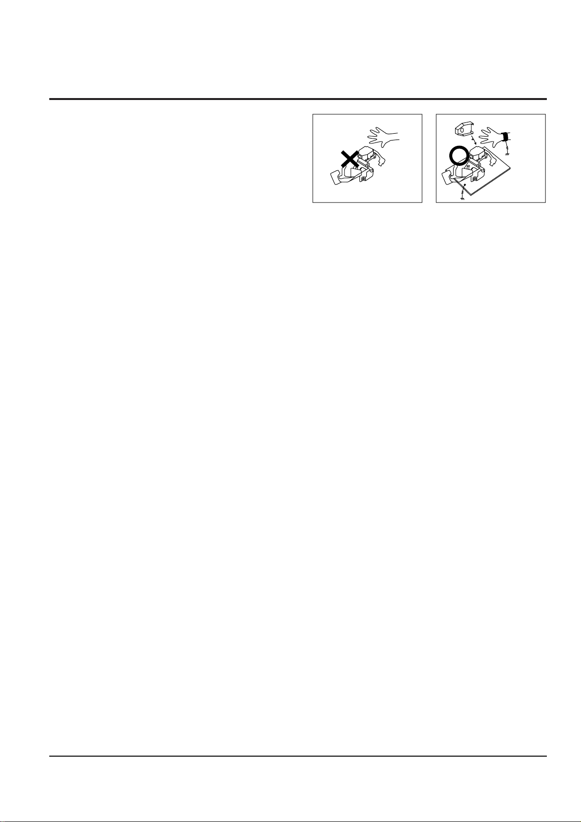
1-2 Handling the optical pick-up
The laser diode in the optical pick up may suffer electrostatic breakdown because of potential static electricity from clothing and your body.
The following method is recommended.
(1) Place a conductive sheet on the work bench (The
black sheet used for wrapping repair parts.)
(2) Place the set on the conductive sheet so that the
chassis is grounded to the sheet.
(3) Place your hands on the conductive sheet(This
gives them the same ground as the sheet.)
(4) Remove the optical pick up block
(5) Perform work on top of the conductive sheet. Be
careful not to let your clothes or any other static
sources to touch the unit.
◆ Be sure to put on a wrist strap grounded to the
sheet.
◆ Be sure to lay a conductive sheet made of copper
etc. Which is grounded to the table.
Fig.1-2
(6) Short the short terminal on the PCB, which is in-
side the Pick-Up ASS’Y, before replacing the PickUp. (The short terminal is shorted when the PickUp Ass’y is being lifted or moved.)
(7) After replacing the Pick-up, open the short termi-
nal on the PCB.
THE UNIT
WRIST-STRAP
FOR GROUNDING
1M
1M
CONDUCTIVE SHEET
Precautions
1-4 Samsung Electronics
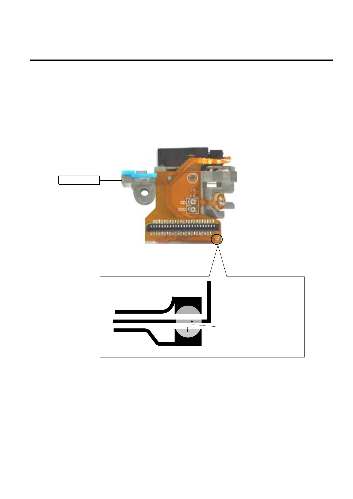
1-3-1 Disassembly
1) Remove the power cord.
2) Disassemble the Deck-Assy.
3) Make solder land 2 points short on Pick-up.
(See Fig. 1-3)
4) Disassembly the Pick-up.
1-3-2 Assembly
1) Replace the Pick-up.
2) Remove the soldering 2 points on Pick-up.
3) Reassemble the Deck-Assy.
SOLDER LAND 2 POINTS SHORT
PICK-UP ASS'Y
Note : If the assembly and disassembly are not done in correct sequence, the Pick-up may be damaged.
Fig. 1-3
1-3 Pick-up disassembly and reassembly
Samsung Electronics
2-1
2. Alignment and Adjustments
2-1 VCR Adjustmant
1) X-Point (Tracking center) adjustment, “Head switching adjustment” and “NVRAM option setting” can be adjusted with remote control.
2) When replacing the VCR Main PCB Micom (IC601) and NVRAM (IC605 ; EEPROM) be sure to adjust the “Head switching adjustment”
and “NVRAM option setting”.
3) When replacing the cylinder ass’y, be sure to adjust the “X-Point” and “Head switching adjustment”.
4) How to adjustment.
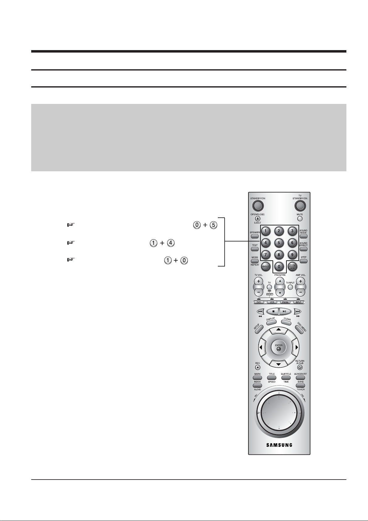
- Press the “SW718 (TEST)” button on Function-Timer PCB to set the adjustment mode.
- If the corresponding adjustment button is pressed, the adjustment is performed automatically.
2-1-1(a) Location of adjustment button of remote control
Fig. 2-1
X-Point (Tracking Center) Adjustment ;
Head Switching Adjustment ;
NVRAM Option Setting ;
2-1-1 Reference
2-2
Alignment and Adjustments
Samsung Electronics
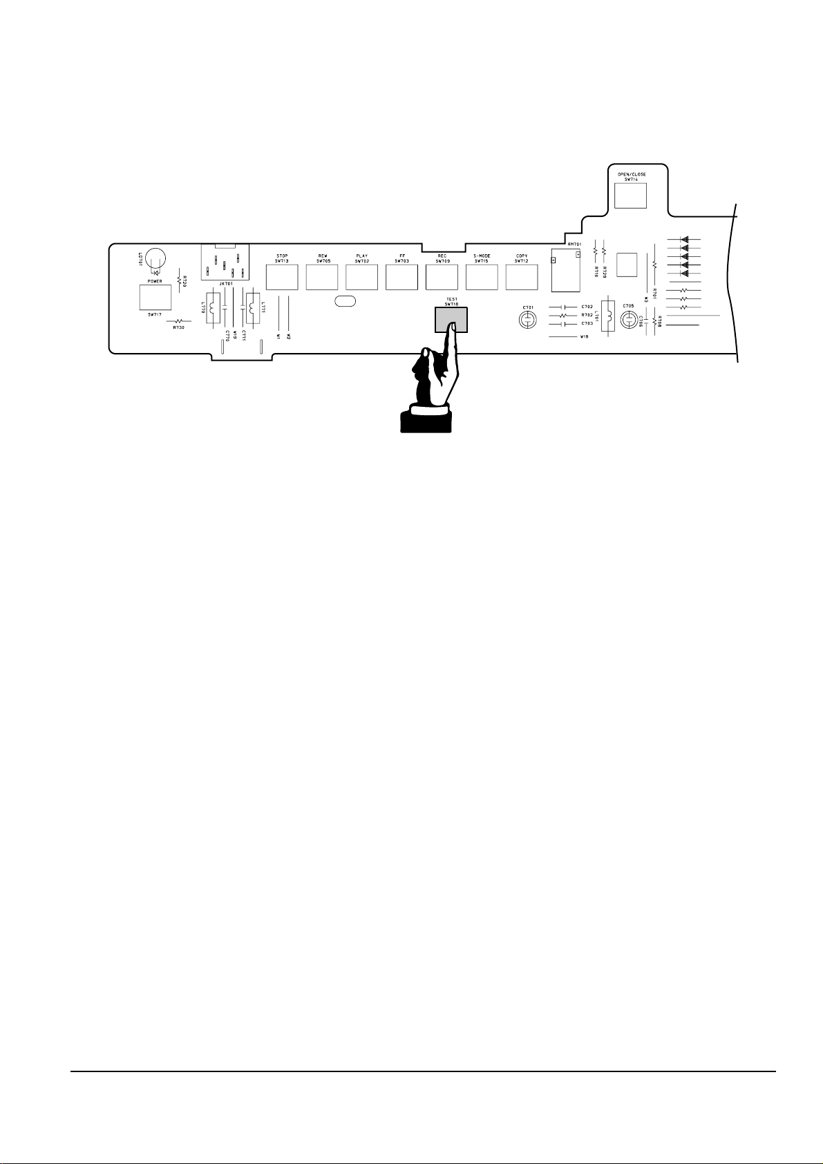
2-1-1(b) TEST location for adjustment mode setting
Fig. 2-2 Function-Timer PCB (Top View)
TEST (SW718) BUTTON
Alignment and Adjustments
2-3
Samsung Electronics
2-1-2 Head Switching Point Adjustment
1) Playback the alignment tape.
2) Press the “SW718(TEST)” button on Function-Timer PCB to set the adjustment mode. (See Fig. 2-2)
3) Press the “1, 0” button of remote control then adjustment is operated automatically. (See Fig. 2-1)
2-1-3 NVRAM Option Setting
1) Press the “SW718(TEST)” button on Function-Timer PCB to set the adjustment mode. (See Fig. 2-2)
2)
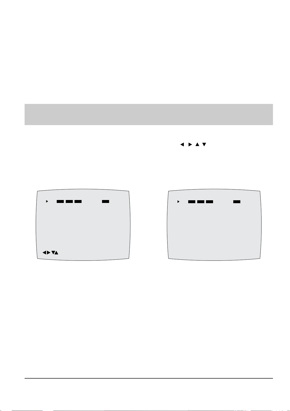
Press the “1, 4” button on the remote control then option setting is appeared. (See Fig. 2-3)
3)
Select the option number (See table 2-1) of corresponding model with “ , , , ” button on the
remote control.
4) If selecting the option number is completed, press the “ENTER ” button of remote control.
(If “ENTER” button is pressed, the selected number is changes reversed color. ; See Fig. 2-4)
5) Press the “RETURN” button of remote control again to store the option number.
6) Turn the Power off.
1) NVRAM Option is adjusted at production line basically.
2) In case VCR Main PCB Micom (IC601) and NVRAM (IC603 ; EEPROM) is replaced, be sure to set the corresponding option number of the
reqaired model. (If the option is not set, the unit is not operated.)
CNG : OK SAVE : RETURN
01 02 03 04 05 06 07 08
09 10 11 12 13 14 15 16
17 18 19 20 21 22 23 24
25 26 27 28 29 30 31 32
33 34 35 36 37 38 39 40
41 42 43 44 45 46 47 48
49 50 51 52 53 54 55 56
57 58 59 60 61 62 63 64
65 66 67 68 69 70 71 72
Fig. 2-3
PLEASE WAIT
01 02 03 04 05 06 07 08
09 10 11 12 13 14 15 16
17 18 19 20 21 22 23 24
25 26 27 28 29 30 31 32
33 34 35 36 37 38 39 40
41 42 43 44 45 46 47 48
49 50 51 52 53 54 55 56
57 58 59 60 61 62 63 64
65 66 67 68 69 70 71 72
Fig. 2-4

2-4
Alignment and Adjustments
Samsung Electronics
<Table 2-1 NVRAM Option Table>
MODELS OPTION NUMBER
DVD-CM350/XEF
2, 4, 5, 6, 7, 8, 9, 10, 11, 12, 13, 15, 20, 21, 23, 26, 29, 32, 33, 34, 35, 36, 40, 46, 47, 60, 61, 63, 65, 66
DVD-CM350/XEU
3, 4, 5, 6, 7, 8, 9, 10, 11, 12, 13, 15, 23, 27, 29, 32, 34, 40, 41, 46, 47, 60, 61, 63, 65, 66
DVD-CM350/XEG
2, 4, 5, 6, 7, 8, 9, 10, 11, 12, 13, 15, 23, 29, 32, 34, 36, 40, 42, 46, 47, 60, 61, 63, 65, 66
DVD-CM350/XET
2, 4, 5, 6, 7, 8, 9, 10, 11, 12, 13, 15, 23, 29, 32, 34, 36, 40, 42, 46, 47, 60, 61, 63, 65, 66
DVD-CM350/XEC
2, 4, 5, 6, 7, 8, 9, 10, 11, 12, 13, 15, 23, 29, 32, 34, 36, 40, 42, 46, 47, 60, 61, 63, 65, 66
DVD-CM350/SED
2, 4, 5, 6, 7, 8, 9, 10, 11, 12, 13, 15, 20, 21, 23, 26, 29, 32, 33, 34, 35, 36, 40, 46, 47, 60, 61, 63, 65, 66
DVD-CM350/XEV
2, 6, 7, 8, 9, 10, 11, 12, 13, 15, 20, 21, 23, 29, 32, 33, 34, 36, 42, 46, 47, 54, 60, 61, 63, 65, 66, 69
DVD-CM350/COM
2, 4, 5, 6, 7, 8, 9, 10, 11, 12, 13, 15, 23, 29, 32, 34, 36, 40, 42, 46, 47, 60, 61, 63, 65, 66
DVD-CM350/XEN
2, 4, 5, 6, 7, 8, 9, 10, 11, 12, 13, 15, 23, 29, 32, 34, 36, 40, 42, 46, 47, 60, 61, 63, 65, 66
DVD-CM350/XENB
2, 4, 5, 6, 7, 8, 9, 10, 11, 12, 13, 15, 23, 29, 32, 34, 36, 40, 42, 46, 47, 60, 61, 63, 65, 66
DVD-CM350/XEP
2, 4, 5, 6, 7, 8, 9, 10, 11, 12, 13, 15, 23, 29, 32, 34, 36, 40, 42, 46, 47, 60, 61, 63, 65, 66
DVD-CM350/XEE
2, 4, 5, 6, 7, 8, 9, 10, 11, 12, 13, 15, 23, 29, 32, 34, 36, 40, 42, 46, 47, 60, 61, 63, 65, 66
DVD-CM350/EUR
2, 4, 6, 7, 8, 9, 10, 11, 12, 13, 15, 20, 23, 29, 32, 33, 34, 36, 42, 46, 47, 60, 61, 63, 65, 66, 69
DVD-CM350/XEO
2, 4, 6, 7, 8, 9, 10, 11, 12, 13, 15, 20, 23, 29, 32, 33, 34, 36, 42, 46, 47, 60, 61, 63, 65, 66, 69
DVD-CM350/FES
2, 4, 6, 7, 8, 9, 10, 11, 12, 13, 15, 20, 23, 29, 32, 34, 36, 42, 46, 47, 60, 61, 63, 65, 66
DVD-CM350/AFR
2, 6, 7, 8, 9, 10, 11, 12, 13, 15, 20, 21, 23, 29, 32, 34, 36, 42, 46, 47, 60, 61, 63, 65, 66
Alignment and Adjustments
2-5
Samsung Electronics
2-2 DVD Adjustment
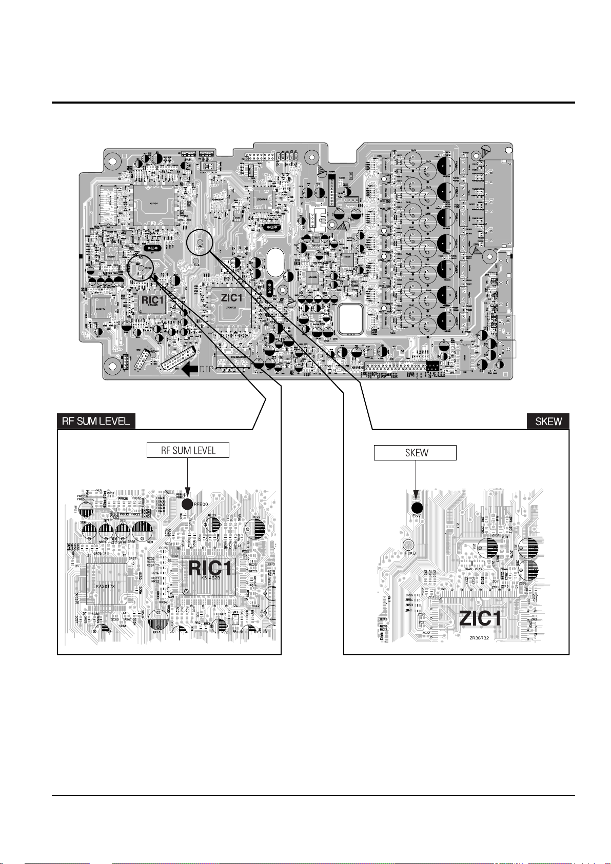
2-2-1 Location of Test Point
Fig. 2-5 Location of test Point (DVD Main PCB - Top Side)
2-6
Alignment and Adjustments
Samsung Electronics
2-2-2(a) Adjustment Spec. and Test Point
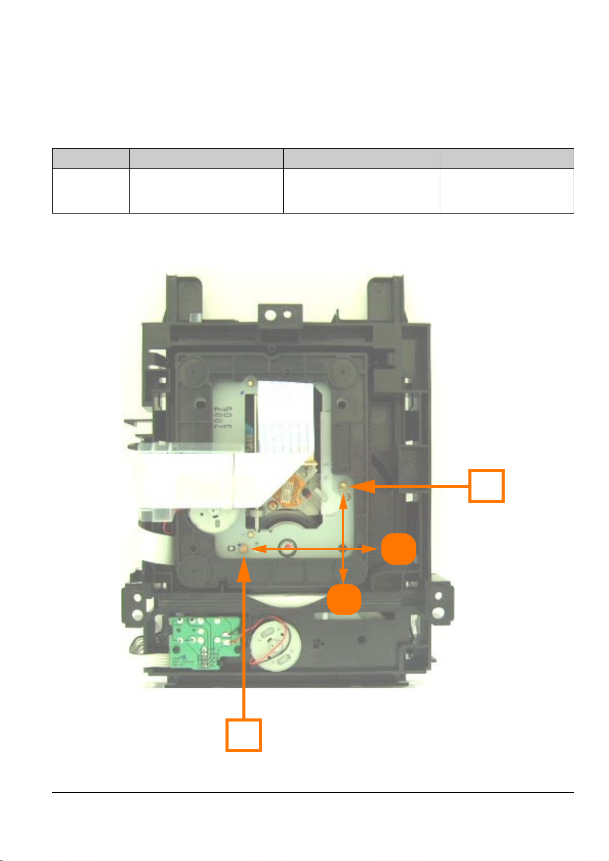
2-2-2 Skew Adjustment
Test Disc Adjustment Spec. Test Point Adjustment Location
TDV-533 “ENV” Ass’y Deck - Bottom Side
Chapter 14 Flat Waveform (DVD Main PCB - Top Side) (See Fig. 2-6)
(See Fig. 2-5)
Fig. 2-6 Ass’y Deck (Bottom Side)
T
R
A
B
◆ Test Disc ; Service not Available
<Table 2-2>
◆
SKEW (Tangential) : The shift on the Vertical axis of Spindle Motor movement.
◆
SKEW (Radial) : The shift on the Direction of the Spindle Motor movement.
Alignment and Adjustments
2-7
Samsung Electronics
2-2-2(b) SKEW Adjustment Method
Needed to minimize the variations in Skew of the Pick-up unit and to provide optimum match with the recorded
signal on the Disc.
1) Remove the Ass’y Deck.
Place the Ass’y Deck on a flat horizontal position.
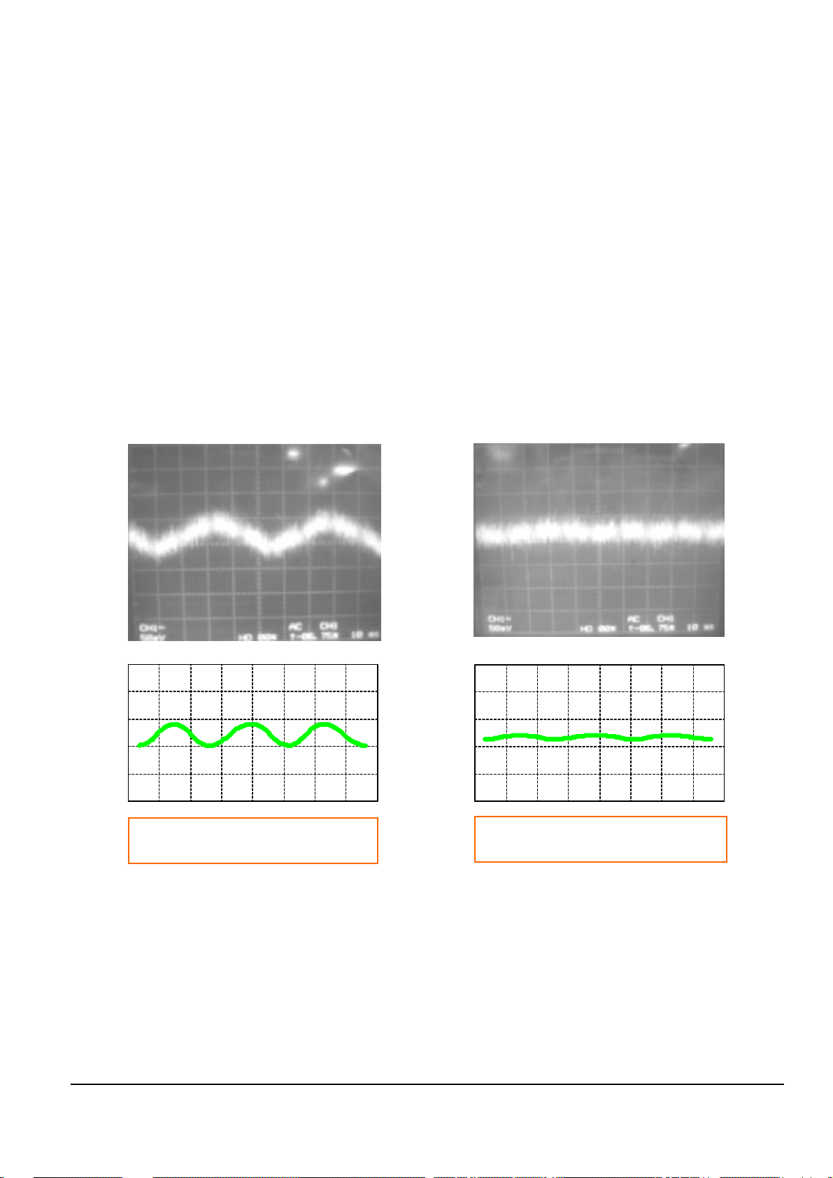
2) Connect an Oscilloscope to the “ENV” Test Point. (See Fig. 2-5)
◆ Set the Oscilloscope Range as follows :
(Voltage ; 50mV/Div., Frequency ; 10m Sec.)
3) Connect Power, Open the Tray and Play the TDV-533 Disc, Chapter 14.
4) Adjust the Screws “A” and “B” (See Fig. 2-6) using a Hex screwdirvier until you obtain a Flat Waveform and
the picture is stable.
Then, go to Chapter 1 and make sure the Waveform is Flat here as well.
If not, you have to go back to Chapter 14 and adjust again.
If you cannot obtain a Flat waveform, then the unit is defective.
Note : The Deck must be in a horizontal position. Use both “A” and “B” screws to adjust, but mostly “A”.
Typical Waveform before Adjustment Waveform after Correct Adjustment
Fig. 2-7 Envelope Waveform
2-8
Alignment and Adjustments
Samsung Electronics
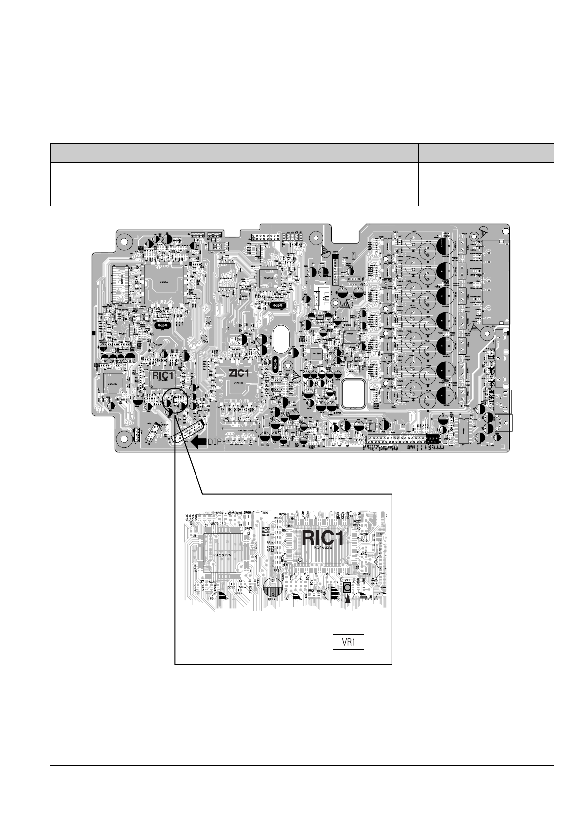
2-2-3(a) Adjustment Spec. and Test Point
2-2-3 RF SUM Level Adjustment
Test Disc Adjustment Spec. Test Point Adjustment Location
“RF EQC” VR1
TDV-525 1.7 ± 0.2V (DVD Main PCB - Top Side) (DVD Main PCB - Top Side)
(See Fig. 2-5) (See Fig. 2-8)
Fig. 2-8 Location of VR1 (DVD Main PCB - Top Side)
<Table 2-3>
Alignment and Adjustments
2-9
Samsung Electronics
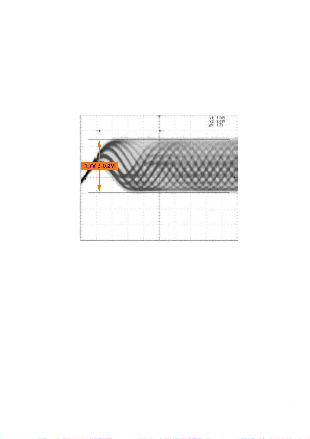
2-2-3(b) RF SUM Level Adjustment Method
1) Connect an Oscilloscope to the “RF EQC ” Test Point. (See Fig. 2-5)
2) Play a Normal DVD disc and set the Oscilloscope Range as follows :
(Voltage ; 50mV/Div., Frequency ; 10m Sec.)
3) Adjust the RF SUM Level by turning the Semi-Variable Resistor (VR1) on the DVD Main PCB (See Fig. 2-8).
4) Adjust according the to table on the previous pages :
◆ 1.7V ± 0.2V
⌘ Warning : Do not turn the Voltage up too high, as this may damage the Laser Diode permanently.
Fig. 2-9 RF SUM Level Wavefrom
2-10
Alignment and Adjustments
Samsung Electronics
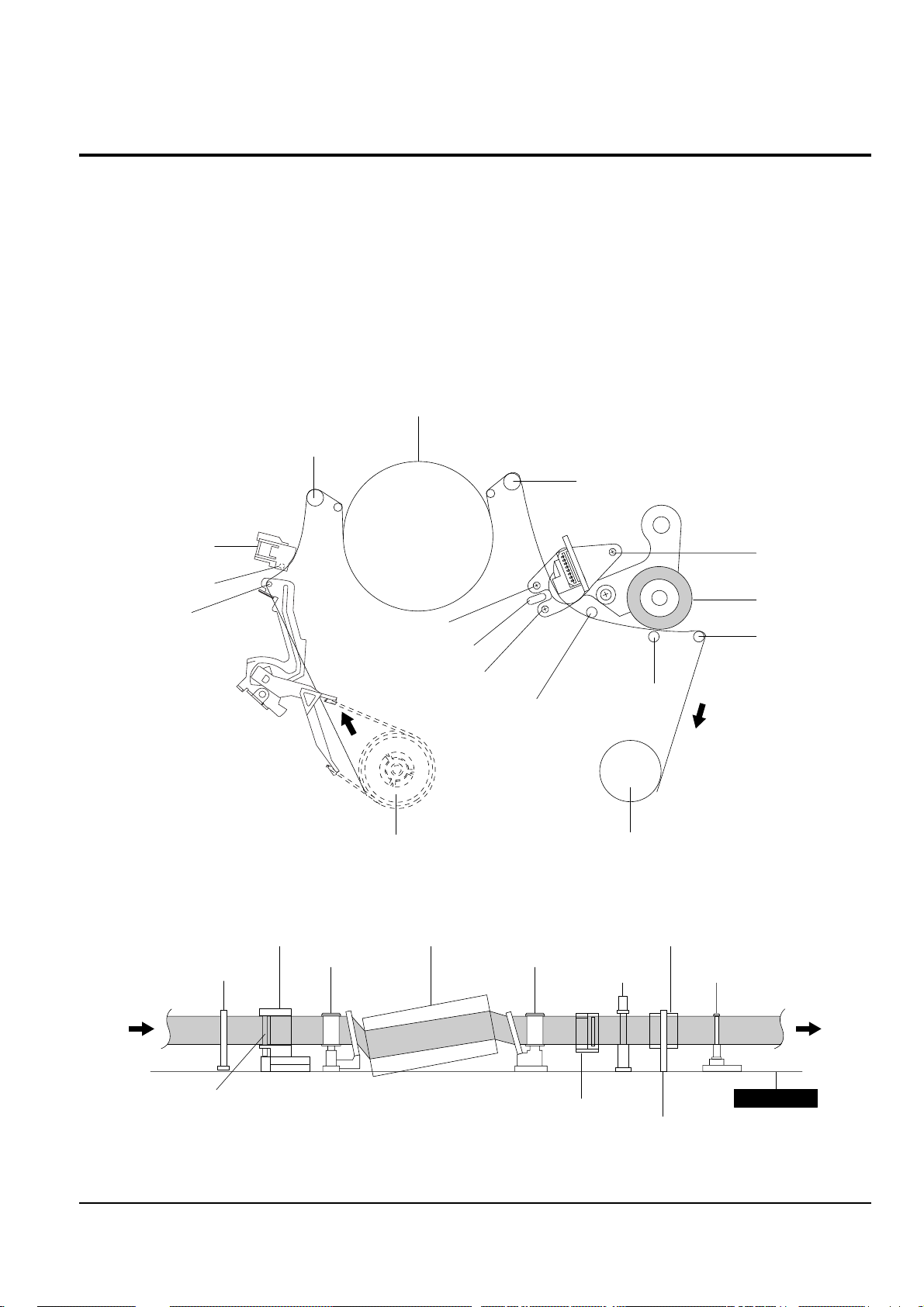
2-3 VCR Mechanical Adjustment
2-3-1 Tape Transport System and Adjustment Locations
The tape transport system has been adjusted precisely in the factory. Alignment is not necessary except for the
following :
1) Noise observed on the screen.
2) Tape damage.
3) Parts replacement in the tape transport system.
Lower flange height of tape guide is used as the reference for the transport adjustment.
To maintain the height of the tape guide and prevent damage, do not apply excessive force onto the main base.
Fig. 2-10 Location of Tape Transport Adjustment
Fig. 2-11 Tape Travel Diagram
CYLINDER ASS'Y
TAKE UP REEL DISK
#8 GUIDE POST
#9 GUIDE POST
SUPPLY REEL DISK
CAPSTAN
PINCH ROLLER
GUIDE ROLLER "T"
GUIDE ROLLER "S"
FULL ERASE HEAD
#3 GUIDE POST
TENSION POST
HEIGHT SCREW
TILT SCREW
X - POSITION
ADJUST SILT
AZIMUTH SCREW
POST TENSION
MAIN BASE
FE HEAD CYLINDER ASS'Y
PINCH ROLLER
GUIDE ROLLER "S" GUIDE ROLLER "T"
#8 GUIDE POST #9 GUIDE POST
CAPSTAN SHAFT
ACE HEAD
#3 GUIDE POST
Alignment and Adjustments
2-11
Samsung Electronics
2-3-2 Tape Transport System Adjustment
When parts are replaced, perform the required adjustments by referring to procedures for the tape transport
system. If there are any changes to the tape path, first run a T-120 tape and make sure excessive tape wrinkle does
not occur at the tape guides.
◆ If tape wrinkle is observed at the guide roller S, T, turn the guide roller S, T until wrinkle disappears.
◆ If the tape wrinkle is still observed at the tape guide, perform the tilt adjustment of the ACE head.
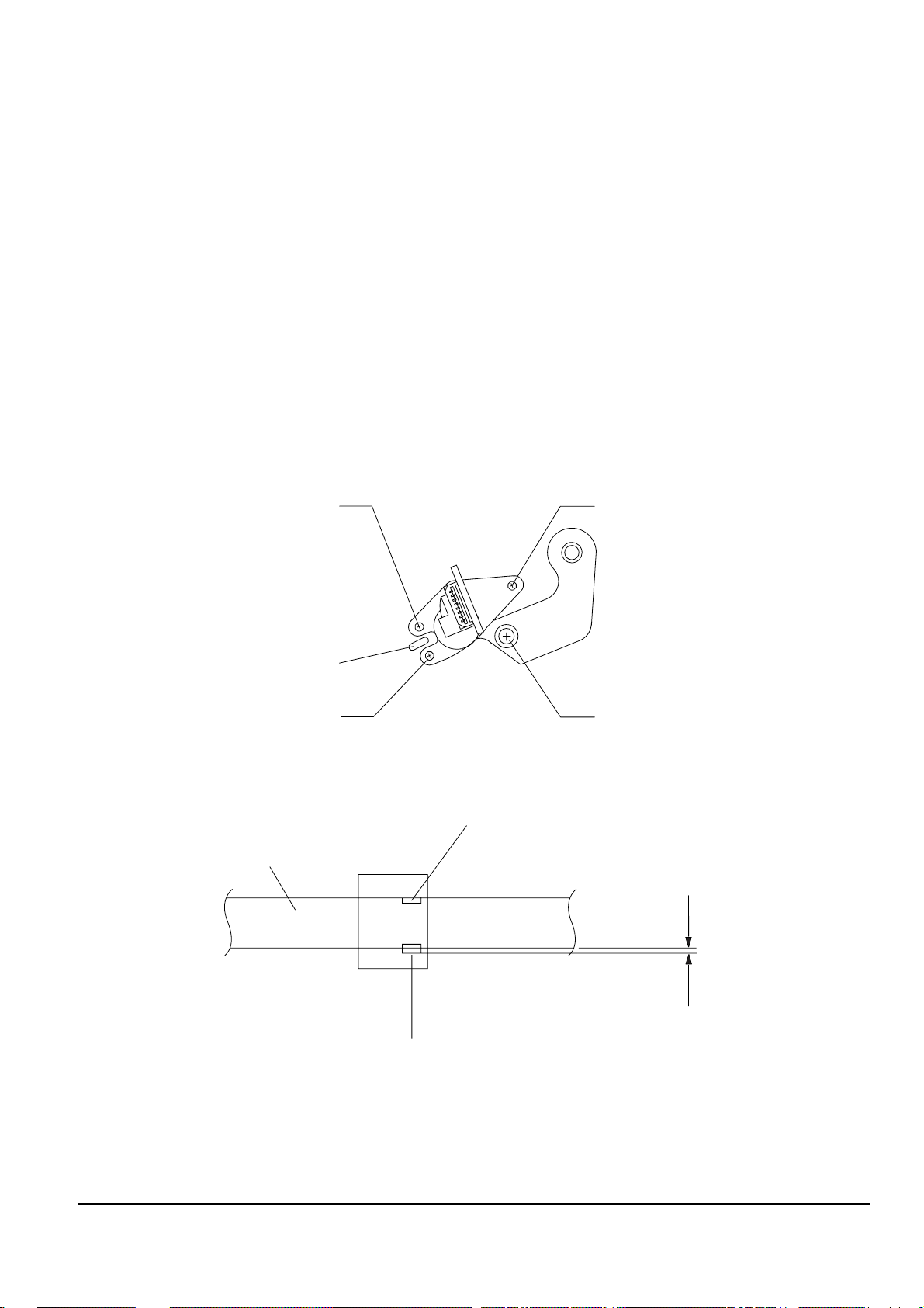
(1) ACE Head Assembly Adjustment
a. ACE HEAD HEIGHT ADJUSTMENT
1) Run the alignment tape (Color bar) in the playback mode.
2) Observe surface of the audio head using a dental mirror.
3) Turn screw (C) clockwise or counterclockwise until the gap of lower tape edge and the lower edge of the
control head is about 0.25mm. (Refer to Fig. 2-12 and 2-13)
Fig. 2-12 Location of ACE Head Adjustment Screw
Fig. 2-13 ACE Head Height Adjustment
SCREW (A)
TLIT ADJUST
X-POSITION
ADJUSTING SLIT
SCREW (C)
HEIGHT ADJUST
SCREW (D)
X-POSITION LOCKING
SCREW (B)
AZIMUTH ADJUST
0 ~ 0 .25 mm
AUDIO HEAD
VIDEO HEAD
CONTROL HEAD
2-12
Alignment and Adjustments
Samsung Electronics
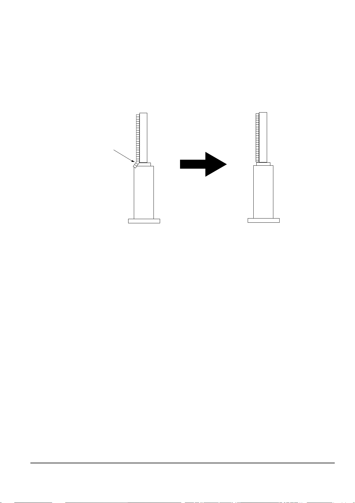
b. ACE HEAD TILT ADJUSTMENT
1) Playback a blank tape and observe the position of the tape at the lower flange of tape guide.
2) Confirm that there is no curl or wrinkle at the lower flange of tape guide as shown in Fig. 2-14 (B).
3) If a curl or wrinkle of the tape occurs, slightly
turn the screw (A) tilt adjust on the ACE head ass’y.
4) Reconfirm the ACE head height.
Fig. 2-14 Tape Guide Check
c. AUDIO AZIMUTH ADJUSTMENT
1) Load alignment tape (Mono scope) and playback the 6KHz signal.
2) Connect channel-1 scope probe to audio output.
3) Adjust screw (B) to achieve maximum audio level. (See Fig. 2-12)
(A) (B)
(BAD)
WRINKLE
(GOOD)
Alignment and Adjustments
2-13
Samsung Electronics
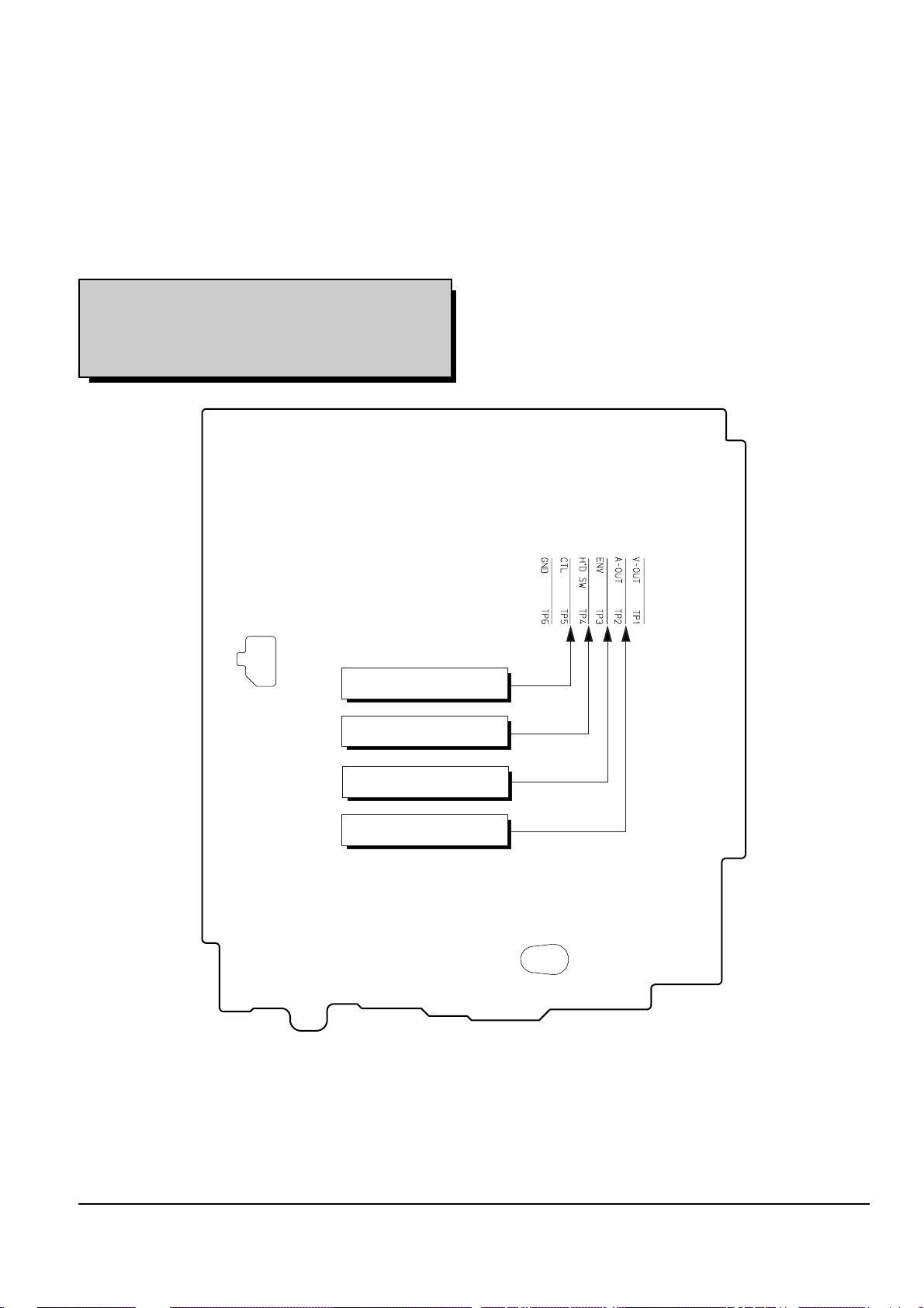
d. ACE HEAD POSITION (X-POINT) ADJUSTMENT
1) Playback the alignment tape (Color bar).
2) Press the “SW718(TEST)” button on Function-Timer PCB to set the adjustment mode. (See Fig. 2-2)
3) Press the “0, 5” button of remote control then adjustment is operated automatically. (See Fig. 2-1)
4) Connect the CH-1 probe to “Envelope” the CH-2 probe to “H’D switching pulse” and then trigger to CH-1.
5) Insert the (-) driver into the X-Point adjustment hole and adjust it so that envelope waveform is maximum.
Test point : TP2 (Audio Output)
TP3 (Envelope)
TP4 (H’D S/W -Trigger)
TP5 (Control Pulse)
Fig. 2-15 Location of Test point (VCR Main PCB-Top View)
AUDIO OUTPUT
CONTROL PULSE
HEAD SWITCHING
ENVELOPE
2-14
Alignment and Adjustments
Samsung Electronics
(2) Linearity adjustment (Guide roller S, T adjustment)
1)
Playback the Mono Scope alignment tape (SP mode).
2) Observe the video envelope signal on an oscilloscope (triggered by the video switching pulse).
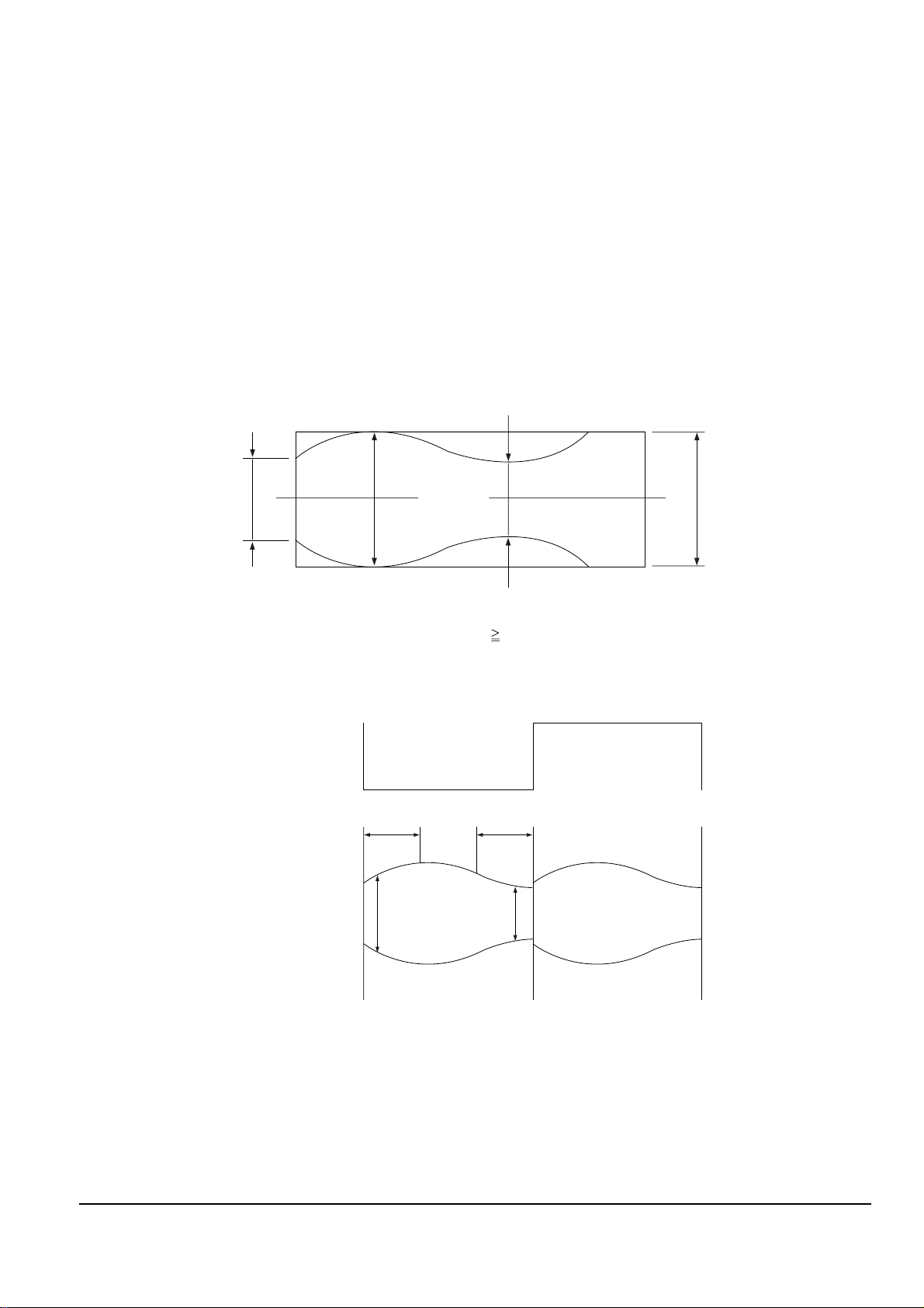
3) Make sure the video envelope waveform (at its minimum) meets the specification shown in Fig. 2-16.
If it does not, adjust as follows :
Note :
a=Maximum output of the video RF envelope.
b=Minimum output of the video RF envelope at the entrance side.
c=Minimum output of the video RF envelope at the center point.
d=Maximum output of the video RF envelope at the exit side.
4) If the section A in Fig. 2-17 does not meet the specification, adjust the guide roller S up or down.
5) If the section B in Fig. 2-17 does not meet the specification, adjust the guide roller T up or down.
Fig. 2-16 Envelope Waveform Adjustment
a
a b c d
c,b,d/a
63%
b
c
d
Fig. 2-17 Adjustment Points
AB
A B
H'D SWITCHING PULSE
ENVELOPE
Alignment and Adjustments
2-15
Samsung Electronics
6) Play back the Mono Scope alignment tape (SP mode).
7) Connect an oscilloscope CH-1 to the “Envelope” and CH-2 to the “H’D SW Pulse” for triggering.
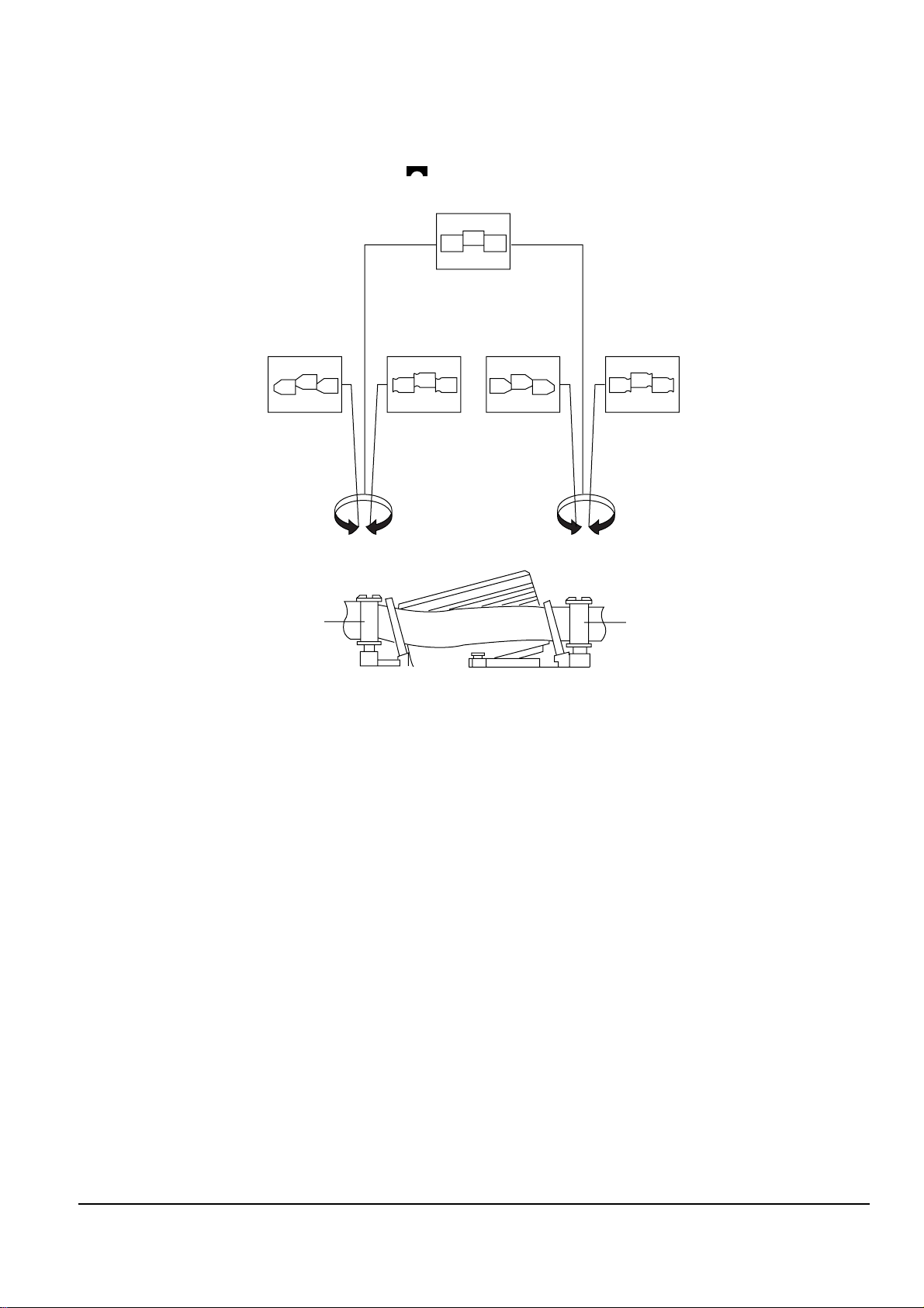
8)
Turn the guide roller heads with a flat head ( ) driver to obtain a flat video RF envelope as shown in Fig. 2-18.
Fig. 2-18 Guide Roller S, T Height Adjustment
IDEAL ENVELOPE
S HEIGHT TOO HIGH
S HEIGHT TOO LOW
T HEIGHT TOO HIGH
T HEIGHT TOO LOW
GUIDE ROLLER S
GUIDE ROLLER T
2-16
Alignment and Adjustments
Samsung Electronics
(3) Check Transitional Operation from RPS to Play
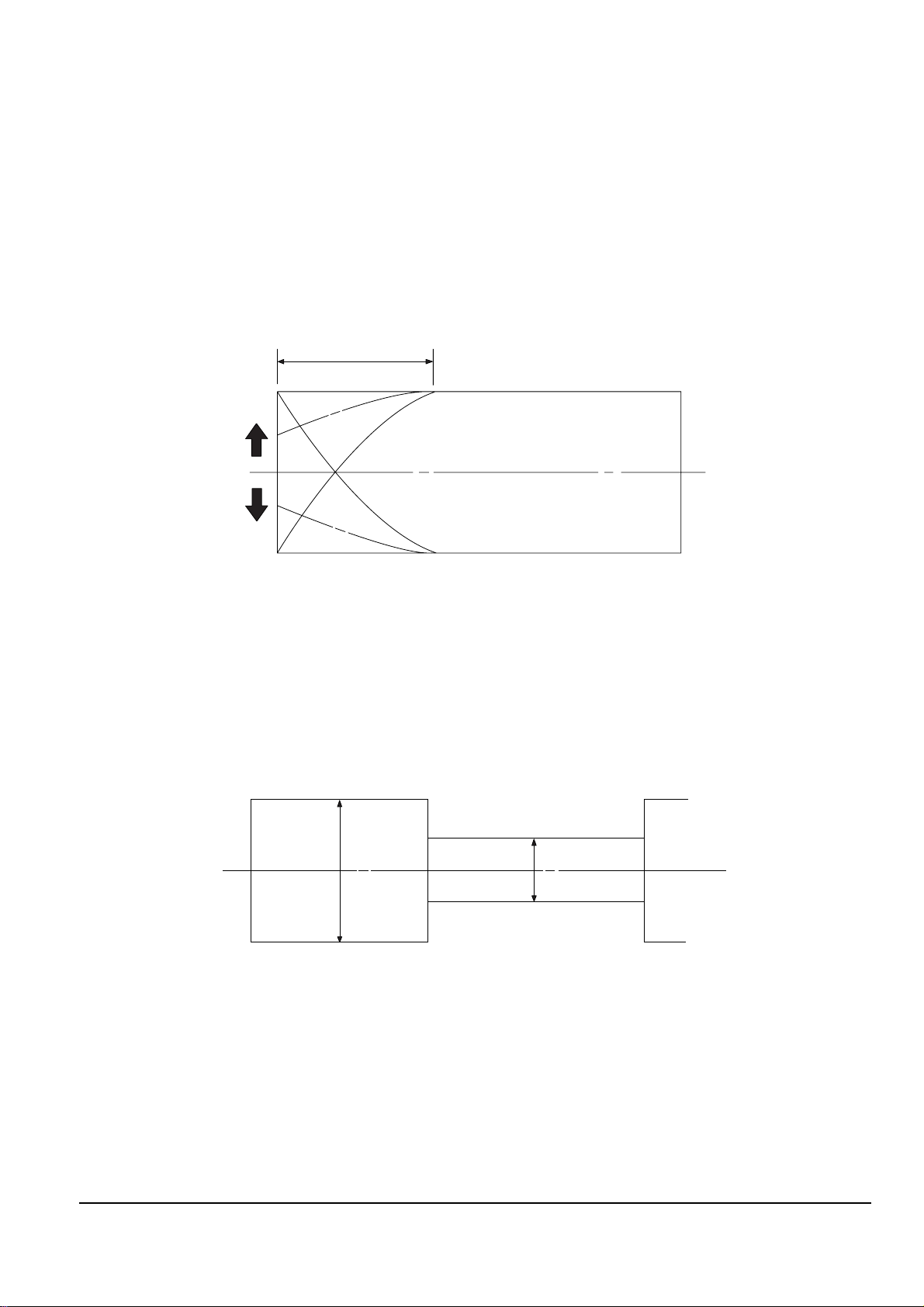
Check transition from RPS mode to play mode : Using a pre-recorded SP tape, make sure the entry side of envelope comes to an appropriate steady state within 3 seconds (as shown in Fig. 2-19).
If the envelope waveform does not reach specified peak-to peak amplitude within 3 seconds, adjust as follows :
1) Make sure there is no gap between the supply roller lower flange and the tape.
If there is a gap, adjust the supply guide roller again.
2) Change operation mode from the RPS to the play mode (again) and make sure the entry side of envelope rises
within 3 second.
ENTRANCE SIDE ENVELOPE
Fig. 2-19 Video Envelope Rising when Operation mode Changes from RPS to Play Mode
(4) Envelope Check
1) Make recordings on T-120 (E-120) and T-160 (E-180) tape.
Make sure the playback output envelope meets the specification as shown in Fig. 2-20.
2) Play back a self recorded tape (recording made on the unit using with T-120 (E-120).
The video envelope should meet the specification as shown in Fig. 2-20.
In SP mode, (A) should equal (B).
If the head gap is wide, upper cylinder should be checked.
A
B
Fig. 2-20 Envelope Input and Output Level
(5) Tape Wrinkle Check
1) Run the T-160 (E-180) tape in the playback, FPS, RPS and Pause modes and observe tape wrinkle at
each guide.
2) If excessive tape wrinkle is observed, perform the following adjustments in Playback mode :
◆ Tape wrinkle at the guide roller S, T section : Linearity adjustment.
◆ Tape wrinkle at tape guide flange : ACE head assembly coarse adjustment.
 Loading...