

Samsung CLX-FIN40S, CLX-FIN40L Service Manual
Service Manual
Finisher Service Manual
CLX-FIN40S / CLX-FIN40L
1. Application Model
• CLX-925x/935x series
• SCX-8x30/8x40 series
2. Stack Capacity (A4/LT 80gsm)
• CLX-FIN40S : 1,000 sheets (Main) / 250 sheets (Top)
• CLX-FIN40L : 3,000 sheets (Main) / 250 sheets (Top)
3. Staple (Finisher)
• Capacity : 50 sheets (90gsm)
• Cartridge Capacity : 5,000 clinching/cartridge
4. Staple (Booklet maker)
• Staple/Fold capacity : 15 sheets
• Cartridge Capacity : 1,000 clinching/cartridge)
The keynote of Product

ⓒ
Samsung Electronics Co.,Ltd. April. 2010
Printed in Korea.
VERSION NO. : 1.00 CODE : FIN4-00000E
GSPN (Global Service Partner Network)
North America : service.samsungportal.com
Latin America : latin.samsungportal.com
CIS : cis.samsungportal.com
Europe : europe.samsungportal.com
China : china.samsungportal.com
Asia : asia.samsungportal.com
Mideast & Africa : mea.samsungportal.com

1.1 General Specif cations …………………………………………… 1-1
1.2 Finisher Specif cations …………………………………………… 1-2
1.3 Booklet Maker Specif cations …………………………………… 1-3
1.4 Media Specif cations …………………………………………… 1-4
1.5 Tray Capacity Specif cations …………………………………… 1-9
1.6 Mode Feature …………………………………………………… 1-10
1.7 Staple Set Specif cations ………………………………………… 1-11
1.8 Hole Punch Specif cations ……………………………………… 1-14
1.9 Booklet Maker Specif cations …………………………………… 1-16
2.1 Front sectional view ……………………………………………… 2-1
a) CLX-FIN40S ……………………………………………………… 2-1
b) CLX-FIN40L ……………………………………………………… 2-2
2.2 Paper path ………………………………………………………… 2-4
a) CLX-FIN40S ……………………………………………………… 2-4
b) CLX-FIN40L ……………………………………………………… 2-5
2.3 Layout of electrical parts ………………………………………… 2-6
a) CLX-FIN40S ……………………………………………………… 2-6
b) CLX-FIN40L ……………………………………………………… 2-8
c) CLX-BRG200 …………………………………………………… 2-12
2.4 Function of units …………………………………………………… 2-13
a) CLX-FIN40S …………………………………………………… 2-13
b) CLX-FIN40L …………………………………………………… 2-14
2.5 Block diagram …………………………………………………… 2-15
2.6 Plug and jack location list ……………………………………… 2-16
chapter 1 Specifi cation
chapter 2 System Confi guration
Contents

3.1 General precautions on disassembly …………………………… 3-1
3.2 CLX-FIN40S disassembly ……………………………………… 3-2
3.2.1 AS-FRAME UNIT …………………………………………… 3-2
3.2.2 AS-COMPILER EJECTOR ………………………………… 3-17
3.2.3 AS-STAPLER ENDFENCE ………………………………… 3-28
3.2.4 ENDFENCE UNIT …………………………………………… 3-34
3.2.5 Finisher exit sensor ………………………………………… 3-35
3.2.6 AS-BELT ……………………………………………………… 3-37
3.3 CLX-FIN40L disassembly ………………………………………… 3-38
3.3.1 AS-FRAME UNIT …………………………………………… 3-38
3.3.2 Booklet unit ………………………………………………… 3-45
3.3.2.1 Feed Pulley …………………………………………… 3-45
3.3.2.2 AS-MAGNET …………………………………………… 3-46
3.3.2.3 Entrance guide sub assy ……………………………… 3-47
3.3.2.4 Pulley, Gear, Belt. ……………………………………… 3-50
3.3.2.5 AS-SADDLE stapler:EH-280 ………………………… 3-51
3.3.2.6 AS-MAIN-PADDLE …………………………………… 3-52
3.3.2.7 JOG UNIT ……………………………………………… 3-52
3.3.2.8 BM paper present sensor ……………………………… 3-54
3.3.2.9 Blade home sensor …………………………………… 3-55
3.3.2.10 CSP- GEAR …………………………………………… 3-56
3.3.2.11 Folding exit sensor …………………………………… 3-57
3.3.2.12 BM entrance sensor & Moving guide home sensor 3-59
3.3.2.13 Stopper guide upper magnet ………………………… 3-60
4.1 Error code and error message ………………………………… 4-1
4.2 Troubleshooting for error code ………………………………… 4-3
4.3 Finisher Self-Test Mode ………………………………………… 4-37
4.4 Adjusting the staple position (CLX-FIN40L) …………………… 4-40
4.5 Adjusting the Paper Skew ……………………………………… 4-43
chapter 4 Troubleshooting
Contents
chapter 3 Replacement procedure

General Precautions
The service should be done by a qualified service technician.
1. Before servicing or maintenance work, be sure to turn off and unplug the equipment first.
2. Be sure to fix and plug in the power cord securely after the service so that no one trips over it.
3. When servicing the machines with the power turned ON, be sure that the touch screen and
rotating/operating sections are working normally.
4. When servicing or maintaining the finisher / punch unit / bridge unit, be careful about the rotating or
operation sections such as gears, pulleys, sprockets, cams, belts, etc.
5. When parts are disassembled, reassembly is basically the reverse of disassembly unless otherwise
noted in this manual or other related materials. Be careful not to reassemble small parts such as screws,
washers, pins, E-rings to the wrong places.
6. Basically, the machine should not be operated with any parts removed or disassembled.
7. Delicate parts for preventing safety hazard problems (such as breakers, door switches, sensors, etc. if
any) should be handled/installed/adjusted correctly.
8. Use suitable measuring instruments and tools.
9. After completing servicing and maintenance of the finisher / bridge unit / punch unit, check operation.
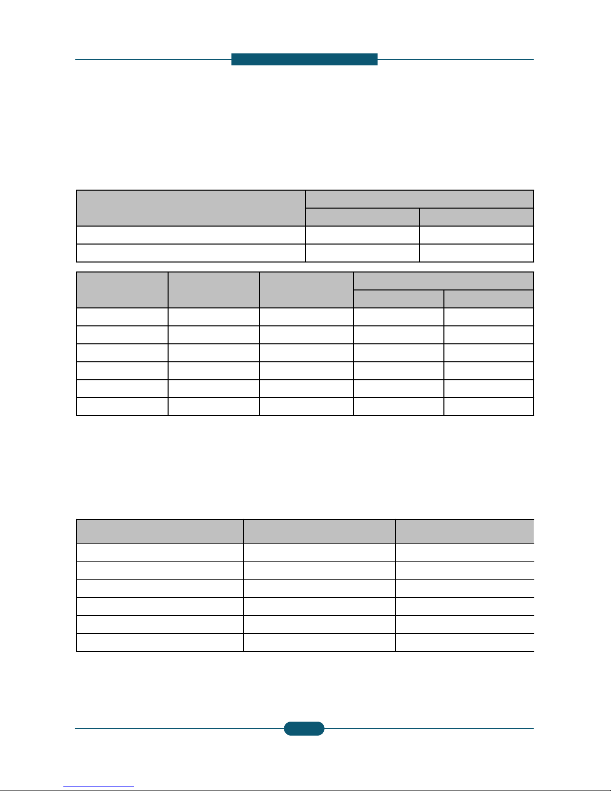
1. Specification
1-1
SAMSUNG ELECTRONICS
Service Manual
CLX-FIN40S/CLX-FIN40L
1. Specifications
- Color Model : 94.8 Kg
- Mono Model : 92.7 Kg
- Color Model : 70.2 Kg
- Mono Model : 68 Kg
- Color Model
876 x 610 x 1074 mm
- Mono Model
876 x 610 x 1018 mm
30.5 KgPacked Weight
25.7 KgModule Weight
Weight
696 x 610 x 536 mm
W x D x HSize
[Finisher]
- Paper feeding / paddling parts : 2,000K
- Finishing parts (Tamping / ejecting / stacking) : 2,000K / 5 sheets job
= 400K
- Finisher Stapler : 300K (maker guaranteed cycle)
90 gsm 2 sheets 5,000 stapling
10 sheets 30,000 stapling
50 sheets 5,000 stapling
: 500K (maker guaranteed cycle)
80 gsm 2 sheets 5,000 stapling
10 sheets 30,000 stapling
50 sheets 5,000 stapling
[Booklet Maker]
- Paper feeding / paddling parts : 2,000K
- parts related folding : 2,000K / 5 sheets job = 400K
- Booklet Stapler : 200K (maker guaranteed cycle)
80 gsm 2 sheets 5,000 stapling
10 sheets 32,000 sheets
25 sheets 3,000 stapling
[Hole punch]
: 1,000K/5 years (maker guaranteed cycle)
SET Life Cycle
150K
Max Monthly
Duty
11KAMPV
Reliability @
Service
Any operation : Non-staple : Non-punch mode
: 56dB(A) run continuous
IOT+Booklet
Finisher
Any operation : Non-staple : Non-punch mode
: 54dB(A) run continuous
Booklet
Finisher only
Acoustic
Noise Level*
10 ~ 90% RHStorage
20 ~ 80% RHOperating
Humidity
-20 ~ 40 ℃Storage
10 ~ 32 ℃Operating
Temperature
CLX-FIN40LCLX-FIN40SItem
1.1 General Specifications

1. Specification
1-2
SAMSUNG ELECTRONICS
Service Manual
CLX-FIN40S/CLX-FIN40L
NA2/3, EU2/4NA2/3, EU2/4available unit
60 ~ 216 gsm60 ~ 216 gsmPaper weight
Hole Punch
YesYesOffline
5,000 clinching/cartridge5,000 clinching/cartridgeCartridge Capacity
50 sheets (90gsm)50 sheets (90gsm)Capacity
60 ~ 216 gsm60 ~ 216 gsmPaper weight
-Front/Rear Corner(45°,Flat)
-Dual
-Front/Rear Corner(45°,Flat)
-Dual
Clinching position
Staple
30mm30mmOffset (Staple/Non Staple)
56 ~ 253 gsm56 ~ 253 gsmTop
60 ~ 216 gsm60 ~ 216 gsmMain
Paper Weight
89 x 148 ~ 12.6 x 18"89 x 148 ~ 12.6 x 18"Top
Statement SEF ~ 12 x 18"Statement SEF ~ 12 x 18"Main
Paper Size
250 sheets250 sheetsTop
3,000 sheets1,000 sheetsMain
Stack Capacity
(A4/LT 80gsm)
Minimized skipMinimized skipStaple
0 Skip0 SkipNon Staple
Skips Pitch
Stand aloneHanging typeConfiguration
CenterCenterPaper alignment
112.5~245 mm/sec112.5~245 mm/secFeed Velocity
25~5025~50PPM
Speed
CLX-FIN40LCLX-FIN40SItem
1.2 Finisher Specifications

1. Specification
1-3
SAMSUNG ELECTRONICS
Service Manual
CLX-FIN40S/CLX-FIN40L
1.3 Booklet Maker Specifications
1,000 clinching/cartridgeStaple Cartridge Capacity
20 sets / 15 sheetsTray Capacity
Max. 216 gsmV folding1 sheet folding mode
15 sheetsStaple/Fold Capacity
Cover sheet = Max. 216 gsm60 ~ 120 gsmPaper Weight
B5 SEF ~ 12 x 18"Paper Size
CenterPaper alignment
112.5~245 mm/secFeed Velocity
Minimized skip25~50PPM
Speed
RemarkCLX-FIN40LItem

1. Specification
1-4
SAMSUNG ELECTRONICS
Service Manual
CLX-FIN40S/CLX-FIN40L
1.4 Media Specifications
OOXOOSEF8.5×13.5215.9×342.9Oficio
OOXOOSEF8.5X13216X330Folio
OOXOOSEF8.5X11216X279Letter
OOXOOSEF8.5X14216X356Legal
OOXOOSEF8.3X11.7210X297A4
OOXOOSEF7.7X10.6195X27016k
OOXOOSEF7.3X10.5184X267Executive
OOXOOSEF6.9X9.8 182X257B5(JIS)
OOXOOSEF6.9×9.8176×250 B5(ISO)
XXXOXSEF6.4×9.0162×229C5 Env
XXXOOSEF5.8X8.3148X210A5
XXXOOSEF5.5X8.5140X216Statement
XXXOXSEF4.5×6.4114×162C6 Env
XXXOXSEF4.3×8.7110×220DL Env
XXXOXSEF4.1×9.5105×241No 10 Env
XXXOXSEF4.1X5.8 105X148A6
XXXOXSEF4.0×6.0101.6×152.4
PostCard
4x6
XXXOXSEF3.9×7.598.4×190.5
Monarch
Env
XXXOXSEF3.9X8.998X225No 9 Env
OXOOOLEF8.3X11.7297X210A4
OXOOOLEF11X8.5279X216Lt
OXOOOLEF10.5X7.3267X184Executive
OXOOOLEF10.1×7.2257X182B5(JIS)
OOXOOLEF8.5X5.5216X140Statement
OOXOOLEF8.3X5.8210X148A5
Flat45°
60-
256 g
60-
216 g
DUAL
Corner
Top
tray
Main
tray
DirectionInchesmm
Staple position OutputOrientationPaper size
Name
a) Output and Staple position
1.4.1 Media Size & mechanism Constraint

1. Specification
1-5
SAMSUNG ELECTRONICS
Service Manual
CLX-FIN40S/CLX-FIN40L
OXOOOSEF10 X14.7254X374Tabloid
OOXOOSEF9.1X12.8229×324C4
OXOOOSEF10.6X15.4270X3908K
OXOOOSEF10X14.3257X364B4
NANANAONA-
W3.5-12.3 ~
L 5.5-18
W 89-312 ~
L 140-457.2
Custom
XXXOXSEF12.6×17.7320×450SRA3
OXOOOSEF12×18304.8×457.2
Tabloid
Extra
OXOOOSEF11.7X16.5297X420A3
OXOOOSEF11X17279X432Ledger
Flat45°
60-
256 g
60-
216 g
DUAL
Corner
Top
tray
Main
tray
DirectionInchesmm
Staple position OutputOrientationPaper size
Name
b) Punch and Booklet Maker
XOXOXXSEF5.8X8.3148X210A5
XOXOXXSEF5.5X8.5140X216Statement
XXXXXXSEF4.5×6.4114×162C6 Env
XXXXXXSEF4.3×8.7110×220DL Env
XXXXXXSEF4.1×9.5105×241No 10 Env
XXXXXXSEF4.1X5.8 105X148A6
XXXXXXSEF4.0×6.0101.6×152.4
PostCard
4x6
XXXXXXSEF3.9×7.598.4×190.5
Monarch
Env
XXXXXXSEF3.9X8.998X225No 9 Env
XOOOOOLEF8.3X11.7297X210A4
XOOOOOLEF11X8.5279X216Lt
XOOOOOLEF10.5X7.3267X184Executive
XOOOOOLEF10.1×7.2257X182B5(JIS)
XOXOXOLEF8.5X5.5216X140Statement
XOXOXOLEF8.3X5.8210X148A5
4H2H3H2H
Scan
4H
EU 2/4HNA 2/3
DirectionInchesmm
Booklet
Maker
PunchOrientationPaper size
Name

1. Specification
1-6
SAMSUNG ELECTRONICS
Service Manual
CLX-FIN40S/CLX-FIN40L
NANANANANANA-
W3.5-12.3 ~
L 5.5-18
W 89-312 ~
L 140-457.2
Custom
XXXXXXSEF12.6×17.7320×450SRA3
OOOOOOSEF12×18304.8×457.2
Tabloid
Extra
OOOOOOSEF11.7X16.5297X420A3
OOOOOOSEF11X17279X432Ledger
OOOOOOSEF10.6X15.4270X3908K
OOOOOOSEF10X14.3257X364B4
OOXOOOSEF10 X14.7254X374Tabloid
OOXOXOSEF9.1X12.8229×324C4
OOXOXOSEF8.5×13.5215.9×342.9Oficio
OOXOXOSEF8.5X13216X330Folio
OOXOXOSEF8.5X11216X279Letter
OOXOXOSEF8.5X14216X356Legal
OOXOXOSEF8.3X11.7210X297A4
OOXOXOSEF7.7X10.6195X27016k
OOXOXOSEF7.3X10.5184X267Executive
OOXOXOSEF6.9X9.8 182X257B5(JIS)
OOXOXOSEF6.9×9.8176×250 B5(ISO)
XXXXXXSEF6.4×9.0162×229C5 Env
4H2H3H2H
Scan
4H
EU 2/4HNA 2/3
DirectionInchesmm
Booklet
Maker
PunchOrientationPaper size
Name
1. Specification
1-7
SAMSUNG ELECTRONICS
Service Manual
CLX-FIN40S/CLX-FIN40L
1.4.2 Media Type & Condition
¾ Special Paper: Finisher must be able to handle special types of papers such as Tab, Archive,
Transparencies, etc (See 1.4.3). A slight underperformance is tolerable for special
papers, however it must not damage the paper in any case.
¾ Static : All static must be controlled so that it would not harm the quality of the stack. Users must never
be shocked by static from the finisher body or finisher’s any module.
¾ Curl : Finisher shall handle ±1/2” curled output as delivered from the IOT.
A1(mm)
A2(mm)
A4(mm)
A3(mm)
Feeding Direction
Radius(R)
10 sheets
Glass
A
A = MAX (A1,A2,A3,A4)
[‘Curl’ measuring method]
¾ Skew : Finisher must be able to control ‘skew’ of the sheet received from the IOT. The skew must be
less than 1% of the length of the paper received from IOT main body (feeding direction).
1. Specification
1-8
SAMSUNG ELECTRONICS
Service Manual
CLX-FIN40S/CLX-FIN40L
1.4.3 Media Performance
The Finisher must be able to control all following types of media.
XXOXOOTab*
XXXXOOLabels (120~150 g/㎡)
XXXXOOTransparency (138~146 g/㎡)
XXXXOXEnvelope(75~90 g/㎡)
XOXOOOThick Glossy (170~216 g/㎡)
XOOOOOThin Glossy (106~169 g/㎡)
XXXOOOThick Cardstock (170~216 g/㎡)
XXOOOOThin Cardstock (105~163 g/㎡)
XXXOOOPre-Punched
OOOOOOLetterHead
OOOOOOArchive
OOOOOOBond
OOOOOORecycled (60~90 g/㎡)
OOOOOOPre-Printed (75~90 g/㎡)
OOOOOOColored (75~90 g/㎡)
OOOOOOCotton (75~90 g/㎡)
OOOOOOThin (60~70 g/㎡)
XXXXOXExtra Heavy weight 2 (217~253 g/㎡)
XOOOOOExtra Heavy weight 1 (176~216 g/㎡)
XOOOOOHeavy weight 2 (121~175 g/㎡)
OOOOOOHeavy weight 1 (106~120 g/㎡)
OOOOOOThick (91~105 g/㎡)
OOOOOOPlain(60~90 g/㎡)
ContentCover
BM
HPStaple
Top
Tray
Main
Tray
Function
Paper Type
*The tab must be positioned on the lead edge as it enters the finisher.
1. Specification
1-9
SAMSUNG ELECTRONICS
Service Manual
CLX-FIN40S/CLX-FIN40L
1.5 Tray Capacity Specifications
1.5.1 Main Tray
The Main Tray must accommodate following capacities. Slight diminishing of the capacity due to buildup
staples can be tolerated, however jamming caused by the buildup blocking the path of ejecting papers must
be prevented.
2,100700Over 70,000 mm
2
3,0001,000Under 70,000 mm
2
CLX-FIN40LCLX-FIN40S
Stack Capacity
Paper Dimension (80gsm)
2,100 700 124,740 297X420A3
2,100 700
120,528 279X432Ledger
2,100 700
76,896 216X356Legal
3,000 1,000
62,370 297X210A4
3,000 1,000
60,264 216X279Letter
3,000 1,000
31,080 210X148A5
CLX-FIN40LCLX-FIN40S
Stack capacity
DimensionSizePaper
¾ The Main Tray may suffer slight degradation of stack quality when it accommodates various types of
papers. (ex. when trying to stack a long paper while the main tray is already stacked with short papers)
1.5.2 Top Tray
The Top Tray must accommodate up to 250 sheets (80gsm Plain Paper) of various types that fits the paper
path. However, the capacity may lessen slightly depending on the condition of the paper received from IOT.
25 sheetsEnvelope
~ 90 sheets200gsm
100 sheets~200 gsm
120 sheets~160 gsm
160 sheets~120 gsm
250 sheets~80 gsm
RemarkStack CapacityPaper Weight
1.5.3 Booklet Maker Tray
The Booklet Maker Tray must be able to accommodate 20 sets of staple folded sheets (Maximum size of a
set = one 216gsm cover page + 80gsm 14 sheets). However, the capacity may lessen slightly depending
on the condition of the paper received from IOT.

1. Specification
1-10
SAMSUNG ELECTRONICS
Service Manual
CLX-FIN40S/CLX-FIN40L
1.6 Mode Feature
¾ Main Stack Mode : Must be able to receive faced-down images from the IOT and stack as much as
3,000 sheets (A4/LT 80gsm) onto the main stacker tray. The Stacker tray must be able to
accommodate various types and sizes of sheets.
¾ Offset Mode : Shifts the space between sets to 30mm in order to distinguish sets that have been
post-processed during Main Stack Mode.
¾ Top Stack Mode : The finisher must be able to assort and discharge papers to the top tray, and
stack as much as 250 sheets(80gsm). Sheets that have been collected to the Top tray cannot access
post-processing functions such as offset, stapling, punching, etc.
¾ Staple Mode : When the user selects this mode, it staples designated corner of the papers that have
to compiled (more than 2 pages).
. Corner staple(Front, Rear): Clinches at 45 degrees from the paper path.
. Dual staple: Clinches at 90 degree from the paper path designated according to the type of paper
¾ In case of simplex copy, the clincher leg must face the back side of the image. The stapler must be
able to clinch as much as 50 sheets (90gsm).
¾ Hole Punch : The punch module should accommodate NA2/3, EU2/4, or Scandinavia 4 hole
module(TBD) depending on the target market. There must be a waste hopper that collects wastes
produced during hole punching. The waste hopper must be big enough to allow at least 5,000
punches before it becomes full.
¾ Booklet Maker Mode : A Dual Stapling must be possible at V-folding line of the paper (that can
cover 15 sheets, or a 216gsm cover + fourteen 80gsm sheets, etc) that goes through the Booklet
maker. The folding is positioned at the centerline of the paper path.

1. Specification
1-11
SAMSUNG ELECTRONICS
Service Manual
CLX-FIN40S/CLX-FIN40L
1.7 Staple Set Specifications
1.7.1 Staple Clinching Position & Accuracy
• Staple Clinching Position changes according to papers types and path directions.
• In Staple mode, papers are passed to the Main Tray. Minimum 2 sheets /set Job is needed in order
to select Staple mode.
45° Rear Corner
B±2 mm
Direction
of Feed
-
+
B±2 mm
Direction
of Feed
(+)
(-)
(+)
(-)
D±2 mm
A±2 mm
Direction
of Feed
45° Front Corner
(+)
(-)
1.0mm1.0mm6.0mmB
Service
Mode
5.0mm5.0mm6.0mmA
Remark(-)(+)
Adjustable amount
NominalDimension
NANA6.0mmD
Service
Mode
5.0mm5.0mm6.0mmA
Remark(-)(+)
Adjustable amount
NominalDimension
Flat Front Corner
D±2 mm
Direction
of Feed
(+)
(-)
Flat Rear Corner
D±2 mm
A±2 mm
Direction
of Feed
(+)
(-)
NANA
6.0mmD
Service
Mode
5.0mm5.0mm6.0mmA
Remark(-)(+)
Adjustable amount
NominalDimension
NANA6.0mmD
Service
Mode
5.0mm5.0mm6.0mmA
Remark(-)(+)
Adjustable amount
NominalDimension
1. Specification
1-12
SAMSUNG ELECTRONICS
Service Manual
CLX-FIN40S/CLX-FIN40L
A = (Paper size_STS/2)-79.5
Depend on paper size
+
+
Dual
D±2 mm
B±2 mm
A±2 mm
Direction
of Feed
(+) (-)
(+)
(-)
NANA148mmD
1.0mm1.0mm6.0mmB
Service
Mode
5mm5.0mmSee blockA
Remark(-)(+)
Adjustable amount
NominalDimension
1. Specification
1-13
SAMSUNG ELECTRONICS
Service Manual
CLX-FIN40S/CLX-FIN40L
1.7.2 Staple Leg quality
The following is Stapler leg quality.
0.8 mm Max
0.9mm Max Flatness0.4mm M 0.6mm Max Burr
1.7.3 Staple Capability
• The Finisher stapler can clinch as much as 50 sheets (90gsm each) and Booklet stapler can clinch as
much as 15 sheets (216gsm 1 cover + 80gsm 14 contents)
• Table of Staple Capacity for each weight-type of papers.
8~120 gsm
12~90 gsm
14~80 gsm
Covers Mode
(1 cover sheet of 216gsm)
10~120 gsm
15~90 gsm
15~80 gsm
No Covers Mode
Booklet
30~120 gsm
40~90 gsm
46~80 gsm
49~75 gsm
50~60 gsm
Covers Mode
(Two cover sheets of 160 gsm)
20~200 gsm
25~160 gsm
33~120 gsm
50~80 gsm
No Covers Mode
Finisher
Number of SheetsPaper WeightModeStaple
The controller controls the maximum number of papers per clinch; however, the user must be aware of the
thickness and the size of the papers that would be clinched. When the user puts in more than the number of
papers that can clinched together, the clinching will not take place. Instead, the user will be required to
select ‘sub-set mode’ or ‘divide clinching’ on the GUI.

1. Specification
1-14
SAMSUNG ELECTRONICS
Service Manual
CLX-FIN40S/CLX-FIN40L
1.8 Hole Punch Specifications
EU 2/4 Hole
Direction
of Feed
a1
Center Line
c
c
c
Ф
b
a2
Z
(+)
(-)
Available Punch Hole
STS Position adjustment
(-)
Available Punch Hole
DOF Position adjustment
X
(+)
NA 3 Hole
Direction
of Feed
Center Line
d
d
Ф
a1
d’
X
a2
Z
(+)
(-)
Available Punch Hole
STS Position adjustment
(-)
Available Punch Hole
DOF Position adjustment
X
(+)
±5.0mm(0.1mm/step)Z±5.0mm(0.1mm/step)Z
±5.0mm(0.1mm/step)X±5.0mm(0.1mm/step)X
8± 0.5 mm8± 0.5 mm
Ф
6.5 ±0.5
mm
6.5 ±0.5
mm
Ф
108±0.5
mm
108±0.5
mm
d 80 ±0.5 mm80 ±0.5 mmc
β±3 mmβ±2 mmd’α±3 mmα±2 mmb
10.5± 3 mm
10.5 ± 2
mm
a1, a2
10. 5 ±3
mm
10. 5 ± 2
mm
a1, a2
99.97%95%99.97%95%
3 Position2 & 4 Position
α = (Paper Size_STS – 3C) ÷ 2 β = (Paper Size_STS - 2d) ÷ 2

1. Specification
1-15
SAMSUNG ELECTRONICS
Service Manual
CLX-FIN40S/CLX-FIN40L
Scandinavia 4 Hole
Direction
of Feed
Center Line
c
d
d
a1
Ф
b
a2
NA 2 Hole
Direction
of Feed
a1
c
Ф
Center Line
b
a2
Z
(+)
(-)
Available Punch Hole
STS Position adjustment
(-)
Available Punch Hole
DOF Position adjustment
X
(+)
Z
(+)
(-)
Available Punch Hole
STS Position adjustment
(-)
Available Punch Hole
DOF Position adjustment
X
(+)
±5.0mm(0.1mm/step)Z
±5.0mm(0.1mm/step)Z±5.0mm(0.1mm/step)X
±5.0mm(0.1mm/step)X6 ± 0.5 mm6 ± 0.5 mm
Ф
8 ± 0.5 mm8 ± 0.5 mm
Ф
21 ± 0.5 mm21 ± 0.5 mmd
70 ± 0.5 mm70 ± 0.5 mmc70 ± 0.5 mm70 ± 0.5 mmc
Ω±3 mmΩ±2 mmbγ± 3 mmγ±2 mmb
10.5 ± 3 mm10.5 ± 2 mma1, a210.5 ± 3 mm10.5 ± 2 mma1, a2
99.97%95%99.97%95%
2 Position (NA)4 Position (Scandinavia)
γ = (Paper Size_STS - c - 2d) ÷ 2 Ω = (Paper Size_STS - c) ÷ 2
* The “X” dimension can be adjust under both service mode and user mode, but the “Z” dimension can be
adjust only service mode.

1. Specification
1-16
SAMSUNG ELECTRONICS
Service Manual
CLX-FIN40S/CLX-FIN40L
1.9 Booklet Maker Specifications
1.9.1 Booklet Staple & Fold Position and Within Set Registration
A
B
120±2mm
Lead
Edge
Center line
Folding Line
Y
X
0 ± 1.5
mm
(Available Folding Line Position Adjustment)
C
(+)
(-)
87.5 ± 2mm228.5 ± 1.5mm304.8 x 457.212 x 18
83.5 ± 2mm210 ± 1.5 mm297 x 420A3
74.7 ± 2mm216.0 ± 1.5mm279 x 432Ledger
43 ± 2mm165.1 ± 1.5 mm216 x 3308.5 x 13
43 ± 2mm178.0 ± 1.5mm216 x 3568.5 x 14
43 ± 2mm139.5 ± 1.5mm216 x 279LT
40 ± 2mm148.5 ± 1.5 mm210 x 297A4
‘B’ Dimension‘A’ DimensionPaper Size
4.0mm2.0mmY
4.0mm2.0mmX
99.97%95%
A4, LT, 8.5x14, 8.5x13, Ledger, A3, 12x18
± 5.0mm (0.1mm/step)426.0mm ≤ L
± 5.0mm (0.1mm/step)358.5mm ≤ L < 426.0mm
± 5.0mm (0.1mm/step)288mm ≤ L < 358.5mm
± 5.0mm (0.1mm/step)L < 288.0mm
‘C’ DimensionPaper Size of DOF (L=Sheet Length)
* The “C” dimension can be adjust under both service mode and user mode. And the staple position follow
that value of “C”.

1. Specification
1-17
SAMSUNG ELECTRONICS
Service Manual
CLX-FIN40S/CLX-FIN40L
1.9.2 Booklet Folding Quality
Folding Line
Z1 Z2
X
Y = Z1 – Z2
3.6mm2.1mm3.0mm1.5mm
Y (as measured on the inside of
the booklet) AZAP
3.1mm1.4mm2.5mm1.0mm
Y (as measured on the inside
sheet of the booklet) B zone,
80gsm (20lbs) paper
25mm22mm35mm30mm
X (measured at any point along
the book) 80gsm (20lbs) or
equivalent papers, ambient
conditions) AZAP
99.97%
Samples
95%
Samples
99.97%
Samples
95%
Samples
Input paper A3 / Ledger / 12x18Input paper A4 / LT / 8.5x13 /
8.5x14
1.9.3 Booklet Staple Leg Quality
A
B C
D
z B < 1.2 mm
z A < B
z A and C < 0.4 mm
z D < 0.4 mm
2. System Configuration
2-1
SAMSUNG ELECTRONICS
Service Manual
CLX-FIN40S/CLX-FIN40L
2. System Configuration
a) CLX-FIN40S
2.1 Front sectional view
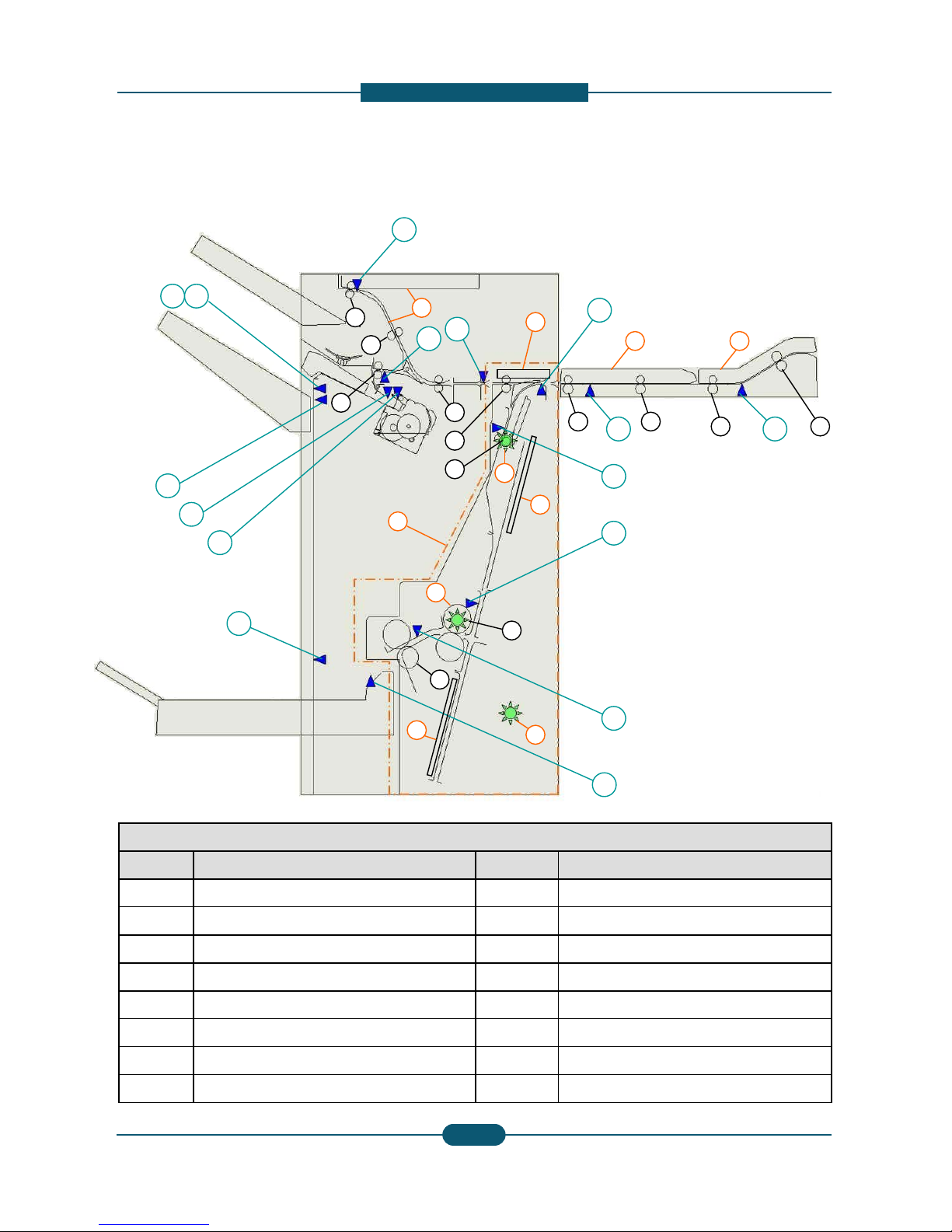
Sensor
No. Name
1 Trans Bridge Input Sensor
2 Trans Bridge Exit Sensor
4 Finisher Input Sensor
5 Finisher Compile Exit Sensor
6 Paper Present Sensor
7 Paper Height Sensor
8 Stacker Upper Limit Emitting Sensor
9 Stacker Upper Limit Receiving Sensor
10 Stack Level Sensor
11 Stacker Bin Full Sensor
12 Finisher Top Exit Sensor
Jam Removal Guide
No. Name
1 Top door guide
2 TB left cover
3 TB right cover
Feed Roller
No. Name
1 Top exit roller
2 Top middle roller
3 Finisher Compile Exit roller
4 Entrance roller
5 TB exit roller
6 TB middle-2 roller
7 TB middle-1 roller
8 TB entrance roller
2. System Configuration
2-2
SAMSUNG ELECTRONICS
Service Manual
CLX-FIN40S/CLX-FIN40L
12
98
10
1
5
6
7
4
3
2 1
11
13
14
16
15
2
3
4
5 6
7 8
9
10
11
12
1
2 3
4
5
6
7
8
9
10
b) CLX-FIN40L
Stacker Upper Limit Emitting Sensor
Paper Height Sensor
Paper Present Sensor
Finisher Compile Exit Sensor
Finisher Input Sensor
Booklet Input Sensor
Trans Bridge Exit Sensor
Trans Bridge Input Sensor
Name
8
7
6
5
4
3
2
1
No.
BM Set Detect Sensor16
Booklet Folding Exit Sensor15
Booklet Compile Present Sensor14
Booklet Compile Exit Sensor13
Finisher Top Exit Sensor12
Stacker Bin Full Sensor11
Stack Level Sensor10
Stacker Upper Limit Receiving Sensor9
NameNo.
Sensor

2. System Configuration
2-3
SAMSUNG ELECTRONICS
Service Manual
CLX-FIN40S/CLX-FIN40L
BM Conveyor Exit Roller12
BM Folding Roller11
BM Compile Exit Roller10
Finisher Trans Roller9
TB Entrance Roller8
TB Middle-1 Roller7
TB Middle-2 Roller6
TB Exit Roller5
Entrance Roller4
Finisher Compile Exit Roller3
Top Middle Roller2
Top Exit Roller1
NameNo.
Feed Roller
BM Knife Knob10
BM Folding Roller Knob9
BM Roller Knob8
BM Stopper Cover7
BM Compile Cover6
Finisher Trans Guide5
Booklet Module4
TB Right Cover3
TB Left Cover2
Top Door Guide1
NameNo.
Jam Removal Guide

2. System Configuration
2-4
SAMSUNG ELECTRONICS
Service Manual
CLX-FIN40S/CLX-FIN40L
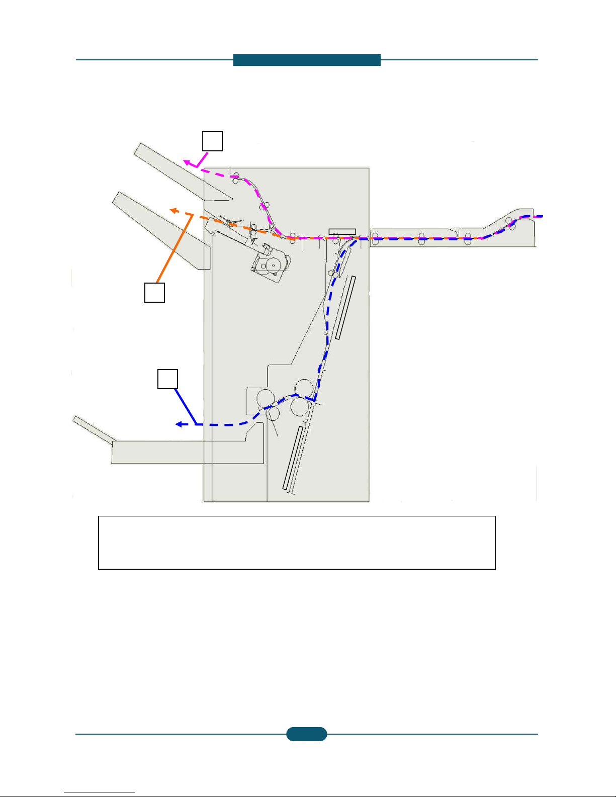
2.2 Paper path
a) CLX-FIN40S
1. Finisher Main Tray - Staple & Punch (Optional)
2. Finisher Top Tray - Punch (Optional)
1
2
2. System Configuration
2-5
SAMSUNG ELECTRONICS
Service Manual
CLX-FIN40S/CLX-FIN40L
1. Finisher Main Tray - Staple & Punch (Optional)
2. Finisher Top Tray - Punch (Optional)
3. Booklet Conveyor Tray – Folding & Staple
b) CLX-FIN40L
2
1
3

2. System Configuration
2-6
SAMSUNG ELECTRONICS
Service Manual
CLX-FIN40S/CLX-FIN40L
2.3 Layout of electrical parts
a) CLX-FIN40S
M2
M1
M3
M5
M4
M6
M7 M8
M9
M10
M11
S1
S2
S3
S4
S5
S6
S7
S8
S9
S10
S11
S12
S13
S14
S15
S16
S17
S18
S19
S20
S21
S22
S24
S26
P1
P2
P3
P4
S25
S23
FunctionDescription
Part Code
Symbol
Diverter Home SensorAS-SENSOR:KIT5011C
JC81-07420A
S5
Feed Entrance SensorPHOTO SENSOR:PS119ED1JC81-03480AS4
Feed Top Exit SensorAS-SENSOR:KIT5011C
JC81-07420A
S3
Feed Compile Exit SensorAS-SENSOR:KIT5011C
JC81-07420A
S2
Offline Stapler SensorAS-SENSOR:KIT5011C
JC81-07420A
S1

2. System Configuration
2-7
SAMSUNG ELECTRONICS
Service Manual
CLX-FIN40S/CLX-FIN40L
Front Cover I/L SwitchAS-MICRO SWITCH:VP333A-0D:LEVERJC81-07404AS26
Top Cover I/L SwitchAS-MICRO SWITCH:VP333A-0D:LEVERJC81-07404AS25
Stacker Upper Limit SwitchMICRO SWITCH:VP333A-0DJC81-03469AS24
SCU Home SensorAS-SENSOR:KIT5011C
JC81-07420A
S23
Stacker Encoder SensorAS-SENSOR:KIT5011C
JC81-07420A
S22
Stacker Bottom Limit SensorAS-SENSOR:KIT5011C
JC81-07420A
S21
Stacker Upper Limit SensorAS-SENSOR:LIS9008HJC81-07403AS20
Stacker Upper Limit SensorAS-SENSOR:KIT5011C
JC81-07420A
S19
Stacker Upper Limit SensorAS-SENSOR:KIS9009HJC81-07396AS18
Stapler Home SensorAS-SENSOR:KIT5011C
JC81-07420A
S17
Stapler Sub SensorAS-SENSOR:KIT5011C
JC81-07420A
S16
Staple Safety SensorAS-SENSOR:KIT5011C
JC81-07420A
S15
Staple Clinching Home SensorAS-SENSOR:KIT5011C
JC81-07420A
S14
Extension Tray Home SensorAS-SENSOR:KIT5011C
JC81-07420A
S13
Ejector Encoder SensorAS-SENSOR:KIT5011C
JC81-07420A
S12
Symbol
Part Code
Description Function
S6
JC81-07420A
AS-SENSOR:KIT5011C Rear Tamper Home Sensor
S7
JC81-07420A
AS-SENSOR:KIT5011C Front Tamper Home Sensor
S8
JC81-07420A
AS-SENSOR:KIT5011C Main Paddle Home Sensor
S9
JC81-07420A
AS-SENSOR:KIT5011C Compile Paper Sensor
S10
JC81-07420A
AS-SENSOR:KIT5011C Eject Limit Sensor
S11
JC81-07420A
AS-SENSOR:KIT5011C Ejector Home Sensor
P1 JC81-07393A AS-PCB MAIN Finisher Main PCB
P2 JC81-07406A AS-PCB OP Offline Staple OP PCB
P3 JC81-07407A AS-PCB STAPLER RELAY Stapler Relay Moving PCB
P4 CF10 8275B
PCB ASSY:STAPLER RELAY FIXED:CFIN
Stapler Relay PCB
M1
JC81-03479A
ASSY:HB MOTOR:S2M19T Feed Entrance Motor
M2
JC81-03479A
ASSY:HB MOTOR:S2M19T Feed Exit Motor
M3 JC81-03486A ASSY:PM MOTOR:S2M12T Front Tamper Motor
M4 JC81-03486A ASSY:PM MOTOR:S2M12T Rear Tamper Motor
M5 JC81-03478A ASSY:PM MOTOR:S2M20T Main Paddle Motor
M6 JC81-07388A AS-MOTOR DC EJECTOR Ejector Motor
M7 JC81-07387A AS-MOTOR PM:Z18:HELICAL Extension Tray Motor
M8 JC81-07389A AS-MOTOR PM:STAPLER Stapler Sub Moving Motor
M9 JC81-07389A AS-MOTOR PM:STAPLER Stapler Main Moving Motor
M10 JC81-03473A ASSY:PM MOTOR:Z18 SCU Motor
M11 CF10 6802A ASSY:3657 DC MOTOR:S2M14T Stacker Moving Motor

2. System Configuration
2-8
SAMSUNG ELECTRONICS
Service Manual
CLX-FIN40S/CLX-FIN40L
S4
M1
M2
M3
M4
M5
M6
M7
M8
M9
M10
M11
S1
M21
S2
S3
S5
S6
S7
S8
S9
S10
S11
S12
S13
S14
S15
S16
S17
S18
S19
S20
S21
S22
S23
SW1
SW2
SW3
S35
P1
P2
P3
P4
b) CLX-FIN40L
Booklet Module
See the next page.
 Loading...