

Page 1
DIGITAL COLOR LASER MFP
CLX-8380 Series
Model : CLX-8380ND/XAA
Basic Model : CLX-8380ND
Manual
SERVICE
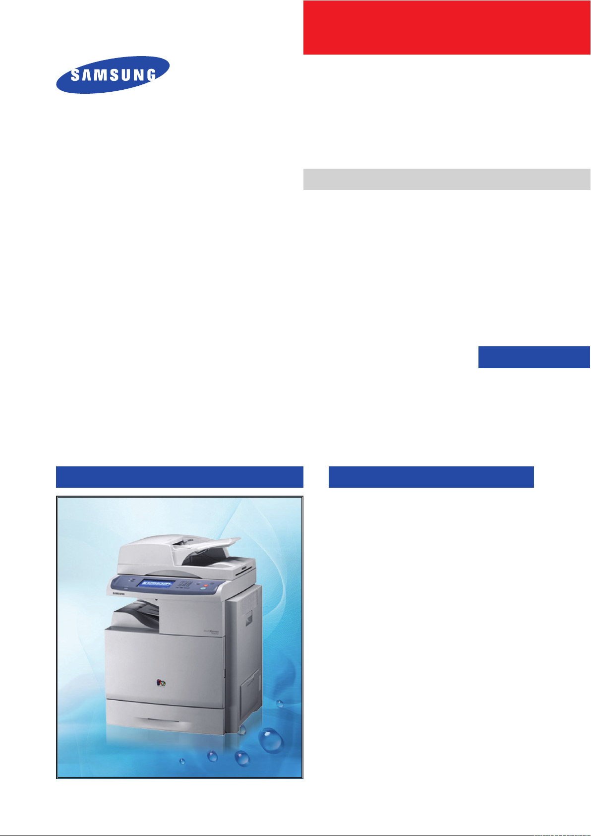
DIGITAL COLOR LASER MFP The keynote of Product
High-Speed Single-Path Color A4 MFP
■ 38 / 38 ppm Network-ready CMFP
■ 20K/15K Black/Color toner
■ 30K CMYK Imaging unit
■ 100K ITB
■ Paper handling
: Up to 3 x 520sh Cassette + 100sh MP
: Finisher with stapler and offset stacking
: 100sh DADF
■ 80 GB HDD
■ High Performance CCDM
■ Easy to install ( CRU & Option )
■ Color Graphic Touch-Screen LCD
■ Low Cost per Page
■ Direct USB
■ S/W Option
: N/W Scan Enabler (Scan to Email/FTP/SMB/
Client)
: SmarThru Workow
Page 2

Contents
1. Precautions
1.1 Safety Warning •••••••••••••••••••••••••••••••••••••••••••••••••••••••1-1
1.2 Caution for safety ••••••••••••••••••••••••••••••••••••••••••••••••••••1-2
1.3 ESD Precautions •••••••••••••••••••••••••••••••••••••••••••••••••••••1-5
1.4 Super Capacitor or Lithium Battery Precautions •••••••••••••••1-5
2. Product spec and feature
2.1 Product Summary ••••••••••••••••••••••••••••••••••••••••••••••••••••2-1
2.2 Specications •••••••••••••••••••••••••••••••••••••••••••••••••••••••••2-3
2.2.1 General Print Engine •••••••••••••••••••••••••••••••••••••••••••2-3
2.2.2 Controller & S/W ••••••••••••••••••••••••••••••••••••••••••••••••2-3
2.2.3 Scan •••••••••••••••••••••••••••••••••••••••••••••••••••••••••••••••2-5
2.2.4 Copy •••••••••••••••••••••••••••••••••••••••••••••••••••••••••••••••2-6
2.2.5 FAX ••••••••••••••••••••••••••••••••••••••••••••••••••••••••••••••••2-7
2.2.6 Paper Handling••••••••••••••••••••••••••••••••••••••••••••••••••2-9
2.2.7 Consumables(CRU) •••••••••••••••••••••••••••••••••••••••••• 2-11
2.2.8 Consumables(FRU) •••••••••••••••••••••••••••••••••••••••••• 2-12
2.2.9 Reliability & Service •••••••••••••••••••••••••••••••••••••••••• 2-12
2.2.10 Options •••••••••••••••••••••••••••••••••••••••••••••••••••••••• 2-13
2.3 System Overview••••••••••••••••••••••••••••••••••••••••••••••••••• 2-14
2.3.1 System Conguration •••••••••••••••••••••••••••••••••••••••• 2-18
2.3.2 H/W Conguration •••••••••••••••••••••••••••••••••••••••••••• 2-19
2.3.3 Mechanic Conguration ••••••••••••••••••••••••••••••••••• 2-37
3. Disassembly and Reassembly
3.1 Maintenance ••••••••••••••••••••••••••••••••••••••••••••••••••••••••••3-1
3.1.1 Precautions on Maintenance •••••••••••••••••••••••••••••••••3-1
3.1.2 Check the consumables life ••••••••••••••••••••••••••••••••••3-2
Page 3

Continued
3.1.3 Consumables List(CRU) ••••••••••••••••••••••••••••••••••••••3-3
3.1.4 Replacing the Consumables. •••••••••••••••••••••••••••••••••3-4
3.1.5 Maintenance Parts(FRU) List ••••••••••••••••••••••••••••••••3-9
3.1.6 Location of Maintenance parts •••••••••••••••••••••••••••• 3-10
3.1.7 Replacing the Maintenance parts ••••••••••••••••••••••••• 3-11
3.1.8 Cleaning the machine •••••••••••••••••••••••••••••••••••••••• 3-21
3.2 Disassembly and Reassembly •••••••••••••••••••••••••••••••••• 3-25
3.2.1 General Precautions on Disassembly •••••••••••••••••••• 3-25
3.2.2 General Disassembly •••••••••••••••••••••••••••••••••••••••• 3-30
4. Alignment & Troubleshooting
4.1 Alignment and Adjustments ••••••••••••••••••••••••••••••••••••••••4-1
4.1.1 Paper path •••••••••••••••••••••••••••••••••••••••••••••••••••••••4-1
4.1.2 Clearing paper Jam ••••••••••••••••••••••••••••••••••••••••••••4-2
4.1.3 Abnormal Image Printing and Defective Roller ••••••••• 4-16
4.1.4 Control Panel overview •••••••••••••••••••••••••••••••••••••• 4-19
4.1.5 Understanding the Status LED ••••••••••••••••••••••••••••• 4-22
4.1.6 Menu overview •••••••••••••••••••••••••••••••••••••••••••••••• 4-23
4.1.7 Firmware Upgrade •••••••••••••••••••••••••••••••••••••••••••• 4-34
4.1.8 Diagnostics •••••••••••••••••••••••••••••••••••••••••••••••••••• 4-38
4.2 Troubleshooting •••••••••••••••••••••••••••••••••••••••••••••••••••• 4-68
4.2.1 Procedure of Checking the Symptoms ••••••••••••••••••• 4-68
4.2.2 Display Meassage Troubleshooting ••••••••••••••••••••••• 4-69
4.2.3 System Diagnostic ••••••••••••••••••••••••••••••••••••••••••• 4-78
4.2.4 H/W problems and solutions ••••••••••••••••••••••••••••••• 4-92
4.2.5 Mechanism problems and solutions •••••••••••••••••••••• 4-97
4.2.6 Image Quality problems and solutions ••••••••••••••••• 4-102
Page 4

Continued
5. Exploded Views & Parts List
Thumbnail •••••••••••••••••••••••••••••••••••••••••••••••••••••••••••••••••••5-2
Harness Summary •••••••••••••••••••••••••••••••••••••••••••••••••••••••••5-5
5.1 Main ••••••••••••••••••••••••••••••••••••••••••••••••••••••••••••••••••• 5-11
5.2 Cover Unit ••••••••••••••••••••••••••••••••••••••••••••••••••••••••••• 5-14
5.3 Cover Front Unit •••••••••••••••••••••••••••••••••••••••••••••••••••• 5-16
5.4 Side Duplex ••••••••••••••••••••••••••••••••••••••••••••••••••••••••• 5-18
5.5 Duplex •••••••••••••••••••••••••••••••••••••••••••••••••••••••••••••••• 5-21
5.6 Feed Idle ••••••••••••••••••••••••••••••••••••••••••••••••••••••••••••• 5-23
5.7 Frame Top ••••••••••••••••••••••••••••••••••••••••••••••••••••••••••• 5-25
5.8 Frame Base ••••••••••••••••••••••••••••••••••••••••••••••••••••••••• 5-27
5.9 MP Unit ••••••••••••••••••••••••••••••••••••••••••••••••••••••••••••••• 5-29
5.10 Pick Up Ass’y ••••••••••••••••••••••••••••••••••••••••••••••••••••••• 5-31
5.11 Frame Lower1 •••••••••••••••••••••••••••••••••••••••••••••••••••••• 5-33
5.12 Frame Lower2 •••••••••••••••••••••••••••••••••••••••••••••••••••••• 5-36
5.13 Bottle Base ••••••••••••••••••••••••••••••••••••••••••••••••••••••••• 5-38
5.14 Registration •••••••••••••••••••••••••••••••••••••••••••••••••••••••• 5-40
5.15 Guide REGI •••••••••••••••••••••••••••••••••••••••••••••••••••••••• 5-42
5.16 Holder OPC •••••••••••••••••••••••••••••••••••••••••••••••••••••••• 5-44
5.17 HV DEVE ••••••••••••••••••••••••••••••••••••••••••••••••••••••••••• 5-46
5.18 WTB Motor ••••••••••••••••••••••••••••••••••••••••••••••••••••••••• 5-48
5.19 Toner Drive ••••••••••••••••••••••••••••••••••••••••••••••••••••••••• 5-50
5.20 LSU Cleaning •••••••••••••••••••••••••••••••••••••••••••••••••••••• 5-52
5.21 Frame Upper •••••••••••••••••••••••••••••••••••••••••••••••••••••• 5-54
5.22 Guide Exit •••••••••••••••••••••••••••••••••••••••••••••••••••••••••• 5-56
5.23 Front OPC Unit •••••••••••••••••••••••••••••••••••••••••••••••••••• 5-58
5.24 Exit Ass’y ••••••••••••••••••••••••••••••••••••••••••••••••••••••••••• 5-60
5.25 Fuser_LV Unit ••••••••••••••••••••••••••••••••••••••••••••••••••••• 5-62
5.26 Cartridge_Transfer ••••••••••••••••••••••••••••••••••••••••••••••• 5-65
5.27 Pusher_LSU ••••••••••••••••••••••••••••••••••••••••••••••••••••••• 5-68
5.28 DEVE Drive •••••••••••••••••••••••••••••••••••••••••••••••••••••••• 5-70
5.29 Fuser Drive •••••••••••••••••••••••••••••••••••••••••••••••••••••••• 5-73
Page 5

Continued
5.30 Main Drive •••••••••••••••••••••••••••••••••••••••••••••••••••••••••• 5-75
5.31 Scanner Ass’y ••••••••••••••••••••••••••••••••••••••••••••••••••••• 5-77
5.32 OPE Unit ••••••••••••••••••••••••••••••••••••••••••••••••••••••••••• 5-79
5.33 Platen Ass’y •••••••••••••••••••••••••••••••••••••••••••••••••••••••• 5-81
5.34 DADF Ass’y •••••••••••••••••••••••••••••••••••••••••••••••••••••••• 5-85
5.35 DADF Sub Ass’y •••••••••••••••••••••••••••••••••••••••••••••••••• 5-87
5.36 Cover Platen_DADF ••••••••••••••••••••••••••••••••••••••••••••• 5-89
5.37 Cover Open_DADF •••••••••••••••••••••••••••••••••••••••••••••• 5-91
5.38 TX Stacker_DADF •••••••••••••••••••••••••••••••••••••••••••••••• 5-93
5.39 Guide Scan_DADF ••••••••••••••••••••••••••••••••••••••••••••••• 5-95
5.40 Guide Pick Up_DADF ••••••••••••••••••••••••••••••••••••••••••• 5-97
5.41 Exit Unit_DADF ••••••••••••••••••••••••••••••••••••••••••••••••••• 5-99
5.42 Cassette •••••••••••••••••••••••••••••••••••••••••••••••••••••••••• 5-101
5.43 SCF ••••••••••••••••••••••••••••••••••••••••••••••••••••••••••••••• 5-103
5.44-1 Main_Finisher•••••••••••••••••••••••••••••••••••••••••••••• 5-107
5.44-2 Frame Unit ••••••••••••••••••••••••••••••••••••••••••••••••• 5-109
5.44-3 Stacker Unit •••••••••••••••••••••••••••••••••••••••••••••••••5-112
5.44-4 Extension Tray Unit ••••••••••••••••••••••••••••••••••••••••5-114
5.44-5 Ejector Unit ••••••••••••••••••••••••••••••••••••••••••••••••••5-116
5.44-6 Compile Unit ••••••••••••••••••••••••••••••••••••••••••••••••5-119
5.44-7 Feed Unit ••••••••••••••••••••••••••••••••••••••••••••••••••• 5-121
5.45 HCF UNIT (Optional Unit) ••••••••••••••••••••••••••••••••••••• 5-124
5.45-1 ELA HOU-HCF •••••••••••••••••••••••••••••••••••••••••••• 5-124
5.45-2 SUB PLATE-BOTTOM ••••••••••••••••••••••••••••••••••• 5-127
5.45-3 SUB UNIT-REAR ••••••••••••••••••••••••••••••••••••••••• 5-129
5.45-4 AS-UNIT FRAME RIGHT •••••••••••••••••••••••••••••••• 5-131
5.45-5 ELA HOU-UPPER •••••••••••••••••••••••••••••••••••••••• 5-133
5.45-6 AS-UNIT CASSETTE •••••••••••••••••••••••••••••••••••• 5-136
5.45-7 MEA UNIT-KNOCK UP •••••••••••••••••••••••••••••••••• 5-138
5.45-8 MEA UNIT-PAPER SIDE R ••••••••••••••••••••••••••••• 5-140
5.45-9 MEA UNIT-PAPER SIDE L •••••••••••••••••••••••••••••• 5-142
5.45-10 SUB GUIDE REAR ••••••••••••••••••••••••••••••••••••• 5-144
Page 6

Continued
6. System Diagram
6.1 Block Diagram ••••••••••••••••••••••••••••••••••••••••••••••••••••••••6-1
6.1.1 System ••••••••••••••••••••••••••••••••••••••••••••••••••••••••••••6-1
6.1.2 Video Controller ••••••••••••••••••••••••••••••••••••••••••••••••6-2
6.1.3 Engin Controller ••••••••••••••••••••••••••••••••••••••••••••••••6-3
6.1.4 OPE Unit •••••••••••••••••••••••••••••••••••••••••••••••••••••••••6-4
6.1.5 DADF •••••••••••••••••••••••••••••••••••••••••••••••••••••••••••••6-5
6.1.6 SCF/HCF •••••••••••••••••••••••••••••••••••••••••••••••••••••••••6-6
6.2 Connection Diagram •••••••••••••••••••••••••••••••••••••••••••••••••6-7
6.2.1 Video Controller •••••••••••••••••••••••••••••••••••••••••••••••••6-7
6.2.2 Engin Controller ••••••••••••••••••••••••••••••••••••••••••••••••6-8
6.2.3 OPE Unit •••••••••••••••••••••••••••••••••••••••••••••••••••••••••6-9
6.2.4 DADF ••••••••••••••••••••••••••••••••••••••••••••••••••••••••••• 6-10
6.2.5 SCF/HCF ••••••••••••••••••••••••••••••••••••••••••••••••••••••• 6-11
7. Reference Information
7.1 Tool for Troubleshooting ••••••••••••••••••••••••••••••••••••••••••••7-1
7.2 Acronyms and Abbreviations •••••••••••••••••••••••••••••••••••••••7-2
7.2.1 Acronyms •••••••••••••••••••••••••••••••••••••••••••••••••••••••••7-2
7.2.2 Service Parts ••••••••••••••••••••••••••••••••••••••••••••••••••••7-4
7.3 A4 ISO 19798 Standard Pattern•••••••••••••••••••••••••••••••••••7-8
7.4 Wireless LAN ••••••••••••••••••••••••••••••••••••••••••••••••••••••• 7-13
7.5 Model Information •••••••••••••••••••••••••••••••••••••••••••••••••• 7-14
7.5.1 Understanding for Model Code •••••••••••••••••••••••••••• 7-14
7.5.2 Understanding Material Code & Name ••••••••••••••••••• 7-15
Page 7

Continued
8. Installation
8.1 Setting up the MFP ••••••••••••••••••••••••••••••••••••••••••••••••••8-1
8.2 Option installation •••••••••••••••••••••••••••••••••••••••••••••••••• 8-11
8.2.1 Options Table •••••••••••••••••••••••••••••••••••••••••••••••••• 8-13
8.2.2 Memory Module ••••••••••••••••••••••••••••••••••••••••••••••• 8-14
8.2.3 Fax Option kit •••••••••••••••••••••••••••••••••••••••••••••••••• 8-16
8.2.4 SCF unit ( Second Cassette Feeder : Optional tray) •• 8-18
8.2.5 HCF unit ( High Capacity Feeder ) •••••••••••••••••••••••• 8-20
8.2.6 Stand (Tall/Small) ••••••••••••••••••••••••••••••••••••••••••••• 8-22
8.2.7 Finisher ••••••••••••••••••••••••••••••••••••••••••••••••••••••••• 8-25
8.2.8 FDI (Foreign device interface) ••••••••••••••••••••••••••••• 8-30
8.3 Setting up the network •••••••••••••••••••••••••••••••••••••••••••• 8-32
8.3.1 Supported operating systems •••••••••••••••••••••••••••••• 8-32
8.3.2 Conguring network protocol via the machine •••••••••• 8-33
8.3.3 Conguring network protocol
by using the SetIP program ••••••••••••••••••••••••••••••••• 8-35
Page 8
Precautions
1. Precautions
In order to prevent accidents and to prevent damage to the equipment please read the precautions listed
below carefully before servicing the printer and follow them closely.
1.1 Safety Warning
(1) Only to be serviced by appropriately qualied service engineers.
High voltages and lasers inside this product are dangerous. This printer should only be serviced by a
suitably trained and qualied service engineer.
(2) Use only Samsung replacement parts
There are no user serviceable parts inside the printer. Do not make any unauthorized changes or
additions to the printer, these could cause the printer to malfunction and create electric shock or re haz-
ards.
(3) Laser Safety Statement
The Printer is certied in the U.S. to conform to the requirements of DHHS 21 CFR, chapter 1 Subchapter
J for Class 1(1) laser products, and elsewhere, it is certied as a Class I laser product con-forming to the
requirements of IEC 825. Class I laser products are not considered to be hazardous. The laser system
and printer are designed so there is never any human access to laser radiation above a Class I level
during normal operation, user maintenance, or prescribed service condition.
Warning >> Never operate or service the printer with the protective cover removed from Laser/
Scanner assembly. The reected beam, although invisible, can damage your eyes.
When using this product, these basic safety pre-cautions should always be followed to
reduce risk of re, electric shock, and injury to persons.
Service Manual
1-1
Samsung Electronics
Page 9

Precautions
Service Manual
1-2
Samsung Electronics
1.2 Caution for safety
1.2.1 Toxic material
This product contains toxic materials that could cause illness if ingested.
(1) If the LCD control panel is damaged it is possible for the liquid inside to leak. This liquid is toxic. Contact
with the skin should be avoided, wash any splashes from eyes or skin immediately and contact your
doctor. If the liquid gets into the mouth or is swallowed see a doctor immediately.
(2) Please keep Imaging Unit and Toner Cartridge away from children. The toner powder contained in the
Imaging Unit and Toner Cartridge may be harmful and if swallowed you should contact a doctor.
1.2.2 Electric Shock and Fire Safety Precautions
Failure to follow the following instructions could cause electric shock or potentially cause a re.
(1) Use only the correct voltage, failure to do so could damage the printer and potentially cause a re or
electric shock.
(2) Use only the power cable supplied with the printer. Use of an incorrectly specied cable could cause the
cable to overheat and potentially cause a re.
(3) Do not overload the power socket, this could lead to overheating of the cables inside the wall and could
lead to a re.
(4) Do not allow water or other liquids to spill into the printer, this can cause electric shock. Do not allow
paper clips, pins or other foreign objects to fall into the printer these could cause a short circuit leading to
an electric shock or re hazard.
(5) Never touch the plugs on either end of the power cable with wet hands, this can cause electric shock.
When servicing the printer remove the power plug from the wall socket.
(6) Use caution when inserting or removing the power connector. The power connector must be inserted
completely otherwise a poor contact could cause overheating possibly leading to a re. When removing
the power connector grip it rmly and pull.
(7) Take care of the power cable. Do not allow it to become twisted, bent sharply round corners or other
wise damaged. Do not place objects on top of the power cable. If the power cable is damaged it could
overheat and cause a re or exposed cables could cause an electric shock. Replace a damaged power
cable immediately, do not reuse or repair the damaged cable. Some chemicals can attack the coating on
the power cable, weakening the cover or exposing cables causing re and shock risks.
(8) Ensure that the power sockets and plugs are not cracked or broken in any way. Any such defects should
be repaired immediately. Take care not to cut or damage the power cable or plugs when moving the
machine.
(9) Use caution during thunder or lightening storms. Samsung recommend that this machine be disconnected
from the power source when such weather conditions are expected. Do not touch the machine or the
power cord if it is still connected to the wall socket in these weather conditions.
(10) Avoid damp or dusty areas, install the printer in a clean well ventilated location. Do not position the
machine near a humidier. Damp and dust build up inside the machine can lead to overheating and
cause a re.
(11) Do not position the printer in direct sunlight. This will cause the temperature inside the printer to rise
possibly leading to the printer failing to work properly and in extreme conditions could lead to a re.
(12) Do not insert any metal objects into the machine through the ventilator fan or other part of the casing, it
could make contact with a high voltage conductor inside the machine and cause an electric shock.
Page 10

Precautions
Service Manual
1-3
Samsung Electronics
1.2.3 Handling Precautions
The following instructions are for your own personal safety, to avoid injury and so as not to damage the
printer
(1) Ensure the printer is installed on a level surface, capable of supporting its weight. Failure to do so could
cause the printer to tip or fall.
(2) The printer contains many rollers, gears and fans. Take great care to ensure that you do not catch your
ngers, hair or clothing in any of these rotating devices.
(3) Do not place any small metal objects, containers of water, chemicals or other liquids close to the printer
which if spilled could get into the machine and cause damage or a shock or re hazard.
(4) Do not install the machine in areas with high dust or moisture levels, beside on open window or close to a
humidier or heater. Damage could be caused to the printer in such areas.
(5) Do not place candles, burning cigarettes, etc on the printer, These could cause a re.
1.2.4 Assembly / Disassembly Precautions
Replace parts carefully, always use Samsung parts. Take care to note the exact location of parts and also
cable routing before dismantling any part of the machine. Ensure all parts and cables are replaced correctly.
Please carry out the following procedures before dismantling the printer or replacing any parts.
(1) Check the contents of the machine memory and make a note of any user settings. These will be erased if
the mainboard or network card is replaced.
(2) Ensure that power is disconnected before servicing or replacing any electrical parts.
(3) Disconnect printer interface cables and power cables.
(4) Only use approved spare parts. Ensure that part number, product name, any voltage, current or
temperature rating are correct.
(5) When removing or re-tting any parts do not use excessive force, especially when tting screws into
plastic.
(6) Take care not to drop any small parts into the machine.
(7) Handling of the OPC Drum
- The OPC Drum can be irreparably damaged if it exposed to light.
Take care not to expose the OPC Drum either to direct sunlight or to uorescent or incandescent
room lighting. Exposure for as little as 5 mins can damage the surface? photoconductive properties
and will result in print quality degradation. Take extra care when servicing the printer. Remove the
OPC Drum and store it in a black bag or other lightproof container. Take care when working with the
covers(especially the top cover) open as light is admitted to the OPC area and can damage the OPC
Drum.
- Take care not to scratch the green surface of OPC Drum Unit.
If the green surface of the Imaging Unit is scratched or touched the print quality will be compromised.
Page 11

Precautions
Service Manual
1-4
Samsung Electronics
1.2.5 Disregarding this warning may cause bodily injury
(1) Be careful with the high temperature part.
The fuser unit works at a high temperature. Use caution when working on the printer. Wait for the fuser to
cool down before disassembly.
(2) Do not put nger or hair into the rotating parts.
When operating a printer, do not put hand or hair into the rotating parts (Paper feeding entrance, motor,
fan, etc.). If do, you can get harm.
(3) When you move the printer
- When transporting/installing the equipment, employ four persons and be sure to hold the positions as
shown in the gure.
The equipment is quite heavy and weighs approximately 78 Kg (including consumables), therefore pay
full attention when handling it.
- Be sure not to hold the movable parts or units (e.g. the control panel, DADF) when transporting the
equipment.
- Be sure to use a dedicated outlet with 110V/220Vpower input.
- The equipment must be grounded for safety.
- Select a suitable place for installation. Avoid excessive heat, high humidity, dust, vibration and direct
sunlight.
- Provide proper ventilation since the equipment emits a slight amount of ozone.
- To insure adequate working space for the copying operation, keep a minimum clearance of 100cm
(3.9 inches) on the left, 300 mm (11.8 inches) on the right and 100 mm(3.9 inches) on the rear.
- The equipment shall be installed near the socket outlet and shall be accessible.
- Be sure to x and plug in the power cable securely after the installation so that no one trips over it.
Page 12

Precautions
Service Manual
1-5
Samsung Electronics
1.3 ESD Precautions
Certain semiconductor devices can be easily damaged by static electricity. Such components are commonly
called “Electrostatically Sensitive (ES) Devices” or ESDs. Examples of typical ESDs are: integrated circuits,
some eld effect transistors, and semiconductor “chip” components.
The techniques outlined below should be followed to help reduce the incidence of component damage
caused by static electricity.
Caution >>Be sure no power is applied to the chassis or circuit, and observe all other safety precautions.
1. Immediately before handling a semiconductor component or semiconductor-equipped assembly, drain
off any electrostatic charge on your body by touching a known earth ground. Alternatively, employ a
commercially available wrist strap device, which should be removed for your personal safety reasons prior
to applying power to the unit under test.
2. After removing an electrical assembly equipped with ESDs, place the assembly on a conductive surface,
such as aluminum or copper foil, or conductive foam, to prevent electrostatic charge buildup in the vicinity
of the assembly.
3. Use only a grounded tip soldering iron to solder or desolder ESDs.
4. Use only an “anti-static” solder removal device. Some solder removal devices not classied as “anti-static”
can generate electrical charges sufcient to damage ESDs.
5. Do not use Freon-propelled chemicals. When sprayed, these can generate electrical charges sufcient to
damage ESDs.
6. Do not remove a replacement ESD from its protective packaging until immediately before installing it. Most
replacement ESDs are packaged with all leads shorted together by conductive foam, aluminum foil, or a
comparable conductive material.
7. Immediately before removing the protective shorting material from the leads of a replacement ESD, touch
the protective material to the chassis or circuit assembly into which the device will be installed.
8. Maintain continuous electrical contact between the ESD and the assembly into which it will be installed,
until completely plugged or soldered into the circuit.
9. Minimize bodily motions when handling unpackaged replacement ESDs. Normal motions, such as
the brushing together of clothing fabric and lifting one’s foot from a carpeted oor, can generate static
electricity sufcient to damage an ESD.
1.4 Super Capacitor or Lithium Battery Precautions
1. Exercise caution when replacing a super capacitor or Lithium battery. There could be a danger of explosion
and subsequent operator injury and/or equipment damage if incorrectly installed.
2. Be sure to replace the battery with the same or equivalent type recommended by the manufacturer.
3. Super capacitor or Lithium batteries contain toxic substances and should not be opened, crushed, or
burned for disposal.
4. Dispose of used batteries according to the manufacture? instructions.
Page 13
Product spec and feature
2. Product spec and feature
2.1 Product Summary
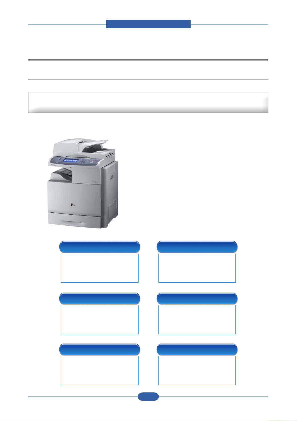
High-Speed Single-Path Color A4 MFP
Document Management Center Machine for Mid & Large Workgroup
■ 38 / 38 ppm Network-ready CMFP
■ 20K/15K Black/Color toner
■ 30K CMYK Imaging unit
■ 100K ITB
■ Machine Life : 1,000K or 5 Years
■ Paper handling
: Maximum 2,720 Sheets Paper Capacity
: Optional Finisher with stapler and offset stacking
: 100sh DADF
■ 80 GB HDD
■ High Performance CCDM
■ Easy to install ( CRU & Option )
■ Color Graphic Touch-Screen LCD
■ Low Cost per Page
■ Direct USB
Low Operational Cost Highly Efcient Features
■ High Performance & Fully
Featured CMFP with
Competitive TCO
■ Document Management &
Workow Solutions
■ Device Administrative & Job
Accounting Solutions
Click-Charge Model Ease of Maintenance
■ Click Charge Business model
for Customers
■ Additional Reseller Revenue
via Supplies & Service Contract
■ Simple Jam Recovery Features
■ Automatic Toner Ordering
Systems
Ease of Use Durability & Reliability
■ Color Touch Screen UI
■ Easy Installable Set & Options
■ Durability better than
competitions
■ Reliability Comparable to
Service Manual
2-1
Samsung Electronics
Page 14

Product spec and feature
Service Manual
2-2
Samsung Electronics
Enhanced Features – H/W
Digital Copying
■ Up to 38 cpm(Color/Mono) in A4
■ 1,200 X 1,200 dpi effective output
■ 1~999 pages multi copy
■ 520 Sheets Cassette Std.
■ Max 2,720 Sheets High Capacity
■ 100 Sheet Multi Purpose Tray
■ 100 Sheet DADF
■ Available Finisher (Offset Stacker / 50
Sheet Stapler)
N/W Color Scanning
■ 4,800 x 4,800 dpi
■ 256 levels gray scale
■ Duplex Scan
Enhanced Features – S/W
Laser Printing
■ Up to 38 ppm(Color/Mono) in A4
■ UP to 9600 Digital Image quality
■ PCL5ce, PCL6, PS3, PDF1.4
■ High Speed USB 2.0 & 10/100
base TX
■ Network Print / Duplex Print
■ Print Job with HDD(Secure, Delay,
Proof, Job Store)
Fax (Optional)
■ 33.6 Kbps modem speed
■ Max. 500-job storage in HDD
■ Max 100 group dials (Max locations
per 1 Group: 200 locations)
■ Caller ID
■ Color Fax Available
Scan Solution
■ Direct Scan to Client
■ Scan to Email / FTP / SMB / HDD
■ SmarThru Workow (Option)(Scan to
Application, OCR, Printer)
Storage
■ Form Overlay Printing
■ e-Form printing
■ Font downloading
N/W Management
■ SyncThru Web Admin Service
■ SyncThru Plug-in Application
■ SyncThru Web Service
Security
■ Authentication (LDAP)
■ Secure / Condential Printing
■ IP Address Filtering
■ Time / Date / ID Stamp
Document Management
■ SmarThru Ofce & SmarThru Workow
■ Capturing of Stored Document &
Distributions of Documents
Job Accounting
■ Job Records Information (Print/Copy/
Scan/Fax)
■ User based History tracking
■ SNMP Job Accounting Access from
SWAS
■ Print/Copy/Scan/Fax log tracking
(HDD, Server)
Page 15
Product spec and feature
Service Manual
2-3
Samsung Electronics
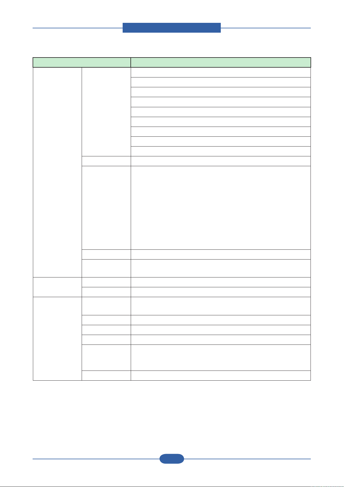
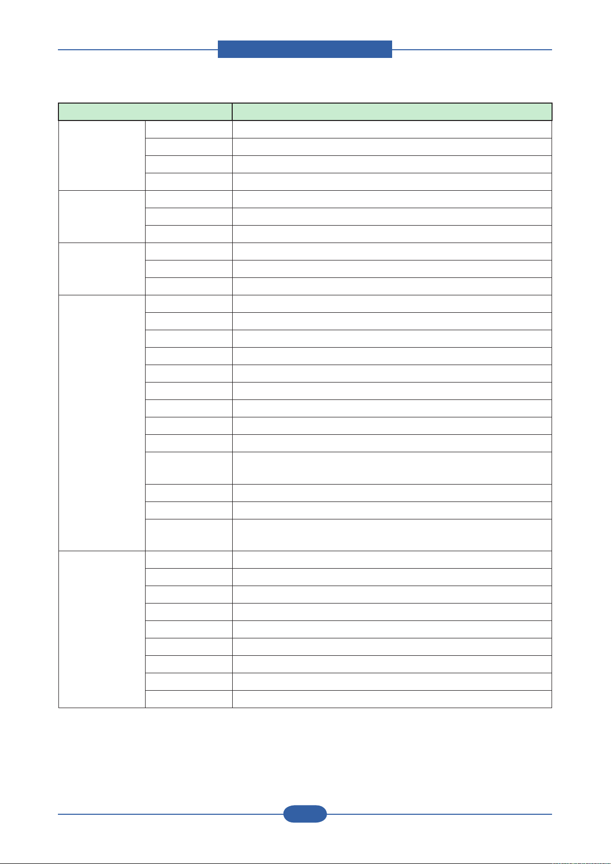
2.2 Specications
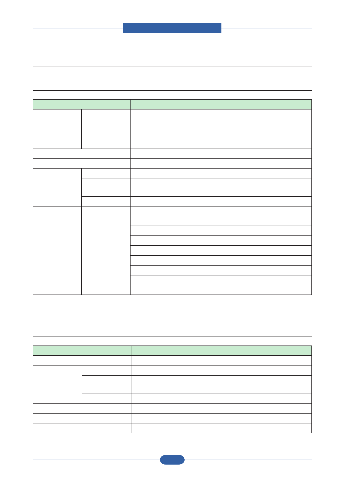
2.2.1 General Print Engine
Item Description
Engine Speed Simplex Up to 38 ppm in A4 black (40 ppm in Letter)
Up to 38 ppm in A4 color (40 ppm in Letter)
Duplex Up to 33 ppm in A4 black (35 ppm in Letter)
Up to 33 ppm in A4 color (35 ppm in Letter)
Warmup time from Power off Less than 120 sec
Warmup time from sleep Less than 30 sec
FPOT From Ready Less than 14 sec
From Power
Save
From Coldboot Less than 135 sec
Resolution Optical 600 x 600 dpi
Support pcl/ps : Draft mode 600x600x1, full speed
45 sec ~ 60 sec Max. (depends on ACR, CTD, or Color tuning)
Normal mode 600x600x2, full speed
Best mode 600x600x4, half speed (=20ppm Letter, simplex)
copy : dadf 300x300 scan, 600x600 print, full speed
f-bed 600x600 scan, 600x600 print, full speed
f-bed Photo 600x600 scan, dither 1200 print, half speed
scan : 300x300 (default), 600x600, 1200x1200
fax : 203x98, 203x196, 300x300, 406x392 (Mono), 200x200 (Color)
2.2.2 Controller & S/W
Item Description
MPU MIPS 720MHz
Memory Std. 320MB (Main 256MB DDR1, Graphic 64MB SDRAM)
Max. 832MB (Main 256MB DDR1, Option 512MB DDR1, Graphic 64MB
SDRAM
HDD 80GB HDD default
Memory Expansion 1 x DDR1 SODIMM Slots (only 1 slot available, 128/256/512 DDR1)
Printer Languages PCL5ce, PCL6, PS, PDF 1.4
Fonts PCL:45 scalable, 1 bitmap , PS:136
Page 16
Product spec and feature
Service Manual
2-4
Samsung Electronics
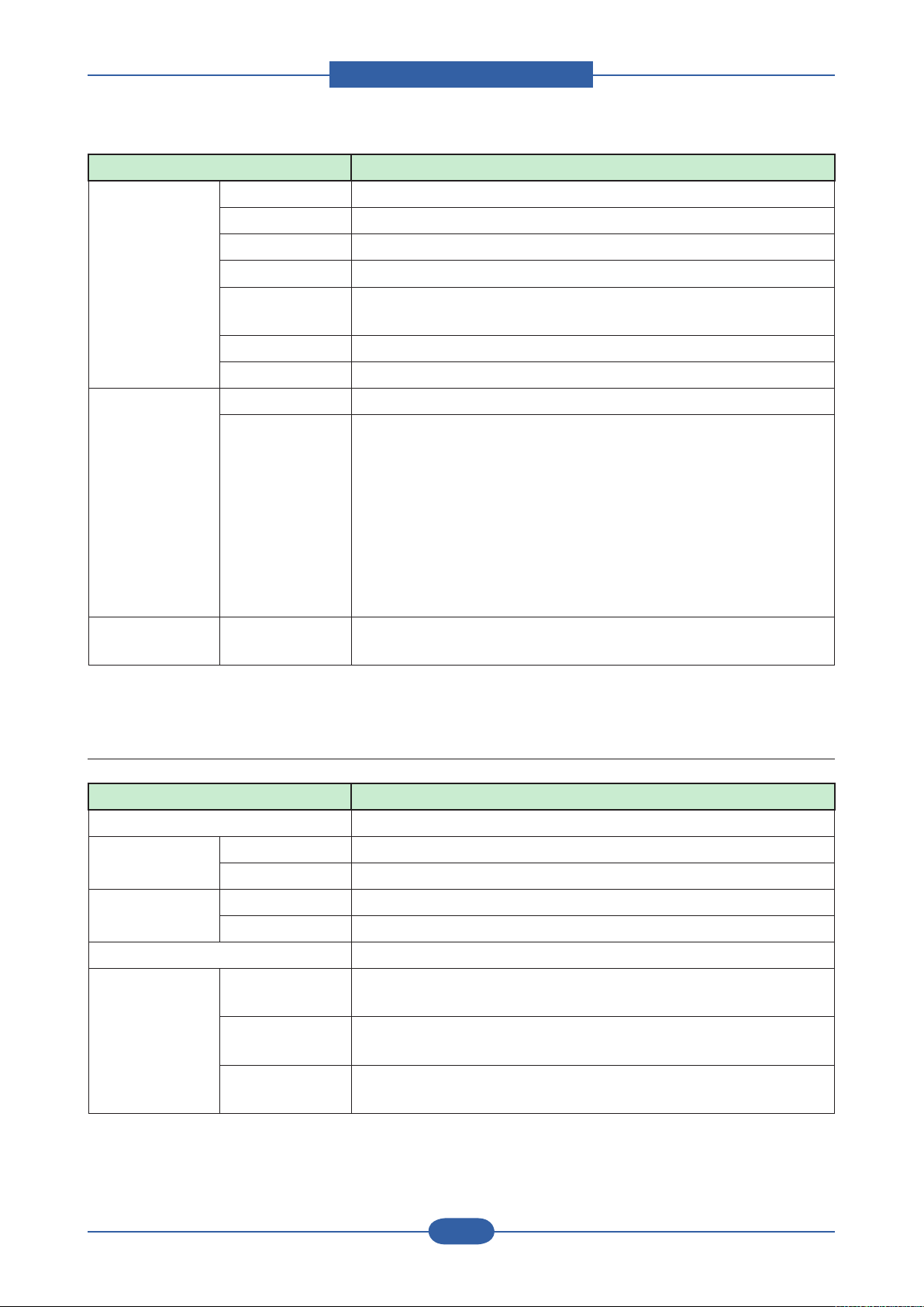
Item Description
Printer driver Supporting OS [Windows]
- Windows 98SE/Me/2000/XP(include 64bit)/2003/Vista
[Linux]
- RedHat 8.0 ~ 9.0
- Fedora Core 1~4
- Madrake 9.2 ~ 10.1
- SuSE 8.2 ~ 9.2
[Mac]
- Mac OS 10.3, 10.4
Default Driver PCL6
Driver feature [Windows]
- Watermark, Overlay, N-up printing, Poster printing
- Manual duplex, Quality, Color mode (Color, Gray scale)
- Support Color spec., Device color, color management [Mac]
- N-up printing, Quality
- Color mode (Color, Gray scale)
[Linux]
- N-up printing, Quality
[Common]
- Include N/W set up on Driver installation
WHQL Windows 2000/XP(include 64bit)/2003/Vista
Language
Localization
Scan driver TWAIN Yes
WIA Yes (N/W, USB2.0 only)
Application Network Scan
Yes (multi-folder), not included Driver CD for the N/W scan functon
(Client)
PC-FAX Yes
RCP Yes
Smart Panel Install Default
Network
Management
Set IP, SAS & SWS
(Linux, Not Support Mac, SWAS and SWS is higher ver.than
Iexplorer 5.0 or higher)
SmarThru Smarthru Ofce
Page 17
Product spec and feature
Service Manual
2-5
Samsung Electronics
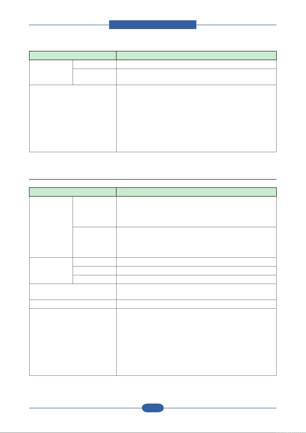
Item Description
Interface Parallel No
USB 1 channel USB 2.0 Peripheral, 1 channel USB 1.1 Host
Network Ethernet 10/100 Base TX
GIGA Network Optional (post launtching)
Wireless
Network
EDI (Jscrive) Optional using USB 2.0 Host port (Post Launching)
FDI Optional (post launching)
Network
Interface
User Interface LCD 800 x 480 7” Color Graphic LCD with Touch-Screen panel, 16bit
Protocol TCP/IP, IPP, SNMP
Network OS [Windows]
Optional (post launtching)
- Microsoft Windows 98/ME/2000/XP/2003/Vista
[Mac]
- Mac OS 10.3, 10.4
[Linux]
- RedHat 8.0 ~ 9.0
- Fedora Core 1~4
- Madrake 9.2 ~ 10.1
- SuSE 8.2 ~ 9.2
color
2.2.3 Scan
Item Description
Scan method Color CCD
Scan Speed
(from DADF)
Resolution Max. Optical 1200*1200ppi
Halftone 256 levels
Scan Size Max. Document
Gray & B/W 35ipm (300dpi,USB2.0,P4 3.0GHz,512M)/Ltr
Color 17ipm (300dpi,USB2.0,P4 3.0GHz,512M)/Ltr
Enhanced 4800*4800ppi
Max.216mm(8.5")
Width
Efective Scan
Width
Max. Document
Length
Max 208mm(8.2inch)
Max.356mm (Legal)
Page 18
Product spec and feature
Service Manual
2-6
Samsung Electronics
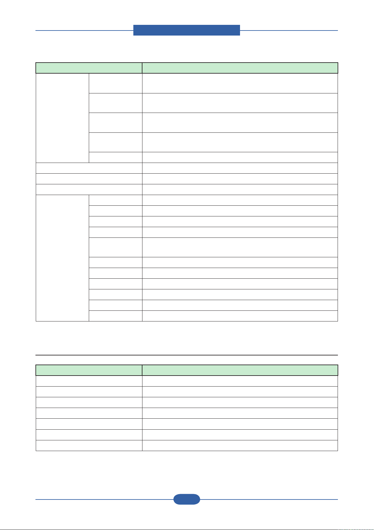
Item Description
Scan Depth Color 24bits
Mono - 1bit for Linearity & Halftone
- 8Bits for Gray scale
Compatibility [Windows]
- Windows 98/Me/2000/XP/2003/Vista
[Mac]
- Mac OS 10.3, 10.4
[Linux]
- RedHat 8.0 ~ 9.0
- Fedora Core 1,2,3,4
- Madrake 9.2 ~ 10.1
- SuSE 8.2 ~ 9.2
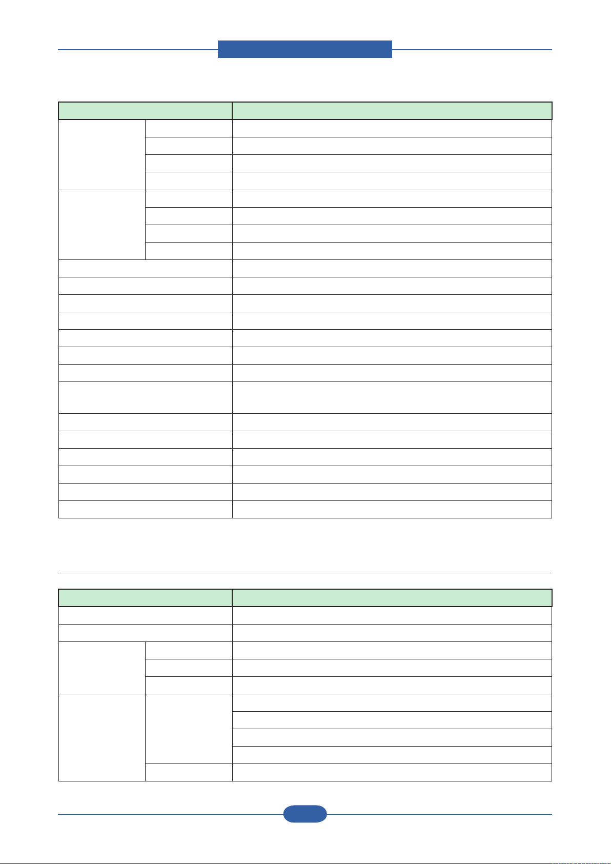
2.2.4 Copy
Item Description
Copy Speed Simplex Copy
Speed
Duplex Copy
Speed
FCOT (Color) From Ready Less than 14 sec
From sleep 45 sec ~ 60 sec Max. (depends on ACR, CTD, or Color tuning)
From Coldboot Less than 135 sec
Zoom Range 25% ~ 400% in 1% increments (Platen)
Multi Copy 1~999
Preset [Original(100%)]
@SDMC up to 38 cpm in A4 black (40 cpm in Letter)
Up to 38 cpm in A4 color (40 cpm in Letter)
@MDMC up to 38 cpm in A4 black (40 cpm in Letter)
Up to 33 cpm in A4 color (35 cpm in Letter)
@SDMC up to 33 cpm in A4 black (35 cpm in Letter)
Up to 28 cpm in A4 color (29 cpm in Letter)
@MDMC up to 24 cpm in A4 black (25 cpm in Letter)
Up to 18 cpm in A4 color (18 cpm in Letter)
25% ~ 200% in 1% increments (DADF)
[A4 → A5(71%)]
[LGL→LTR(78%)]
[LGL→A4(83%)]
[A4→LTR(94%)]
[EXE→LTR(104%)]
[A5 → A4(141%)]
25%, 50%,150%, 200%, 400%
[Custom:25-400%)]
Page 19
Product spec and feature
Service Manual
2-7
Samsung Electronics
Item Description
Original Type Text Platen : Scan 600x600dpi, Printing 600x600dpi
DADF : Scan 300x300dpi, Printing 600x600dpi
Text/Photo Platen : Scan 600x600dpi, Printing 600x600dpi
DADF : Scan 300x300dpi, Printing 600x600dpi
Magazine Platen : Scan 600x600dpi, Printing 600x600dpi
DADF : Scan 300x300dpi, Printing 600x600dpi
Photo Platen : Scan 600x600dpi, Printing 1200x1200dpi
DADF : Scan 300x300dpi, Printing 600x600dpi
Factory Default Mono copy Text/Photo mode
Automatic Background Suppression Available at Mono Copy only, default setting is turned off
Darkness Control 5 level
Collation Copy Yes (ADF only), Job cancel if HDD is full(Color/Mono)
Special Copy ID Card Copy Yes (Platen Only)
Auto t Yes (Platen Only)
Margin Shift Yes
Book Copy Yes
Auto
Suppression
Covers Yes
Transparencies Yes
Create Booklet Yes
N-up copy 2-up, 4-up (ADF only)
Clone Yes (Platen Only)
Poster Yes (Platen Only, X9 Only)
Yes
2.2.5 FAX
Item Description
Compatibility ITU-T G3
Communication System PSTN/PABX
Modem Speed 33.6Kbps, SiLab Fax Modem Card
TX Speed 3sec (Mono/Standard/ECM-MMR, @ ITU-T G3 No.1)
Compression MH/MR/MMR/JBIG/JPEG
Color Fax Yes
ECM Yes
Page 20
Product spec and feature
Service Manual
2-8
Samsung Electronics
Item Description
Resolution
(Mono)
Std 203*98dpi
Fine 203*196dpi
S.Fine 300*300dpi
S.Fine 406*392dpi
Resolution
(Color)
Std 200*200dpi
Fine 200*200dpi
S.Fine 200*200dpi
Scan speed Std 1.5sec/LTR
Fine 4sec/LTR
S.Fine Depends on Document
Telephone
Features
Handset No
On hook Dial Yes
Search Yes (Phone Book)
1-Touch Dial 40 items (using LCD UI)
Speed Dial 200 locations
TAD I/F Yes
Tone/Pulse Selectable in Tech Mode
Pause Yes
Auto Redial Yes
Last Number
Yes
Redial
Distinctive Ring Yes
Caller ID No
External Phone
Yes
Interface
Functions Mail Box No
Voice Request No
TTI Yes
RTI Yes
Polling No
Earth/Recall No
Auto Reduction Yes
SMS No
RDS Yes
Page 21
Product spec and feature
Service Manual
2-9
Samsung Electronics
Item Description
Report & List
Print out
Sound Control Ring Volume Yes (Off,Low,MED,HIGH)
Junk Fax barrier Yes
Security Receive Yes
Battery Backup No
Rx fax duplex print out No
Receive Mode Fax, TEL, Ans/Fax
Capacity 500 items or 1GB (using HDD only)
Optional Memory No
Max locations to store to 1 Group
Dial
Fax Forward to FAX Yes(On/Off), both Sent and Received
Tx/Rx Journal Yes
Conrmation 2 types available (with Image TCR, w/o image TCR,Mono Only)
Auto Dial List Yes
System Data List List all user setting
Key Volume Yes (On,Off)
Speaker Yes (On,Off)
Alarm Volume Yes (On,Off)
199 locations
Fax Forward to e-mail Yes
Broadcasting up to 209 locations
Cover page No
Delayed fax Yes (Tx only)
Memory RX Yes
2.2.6 Paper Handling
Item Description
Standard Capa. 520-sheet cassette Tray (75g/㎡), 100-sheet MP tray (75g/㎡)
Max. Capa. 2,720 sheets @ 20lb(75g/㎡)
Printing Max. Size 216 x 900mm (8.5" x 35.4") (from MP and not installed nisher only)
Min. Size 98 x 148 mm (3.85"x5.83")
Margin(T/B/L/R) 4 mm, 4 mm, 4 mm, 4 mm
Bypass Tray Capacity Plain paper:100 sheets
Transparency:20 sheets
Envelopes:10 sheets
Labels:10 sheets
Media sizes 98 x 148 mm (3.85" x 5.83") ~ 216 x 900 mm (8.5" x 35.4")
Page 22

Product spec and feature
Service Manual
2-10
Samsung Electronics
Item Description
Media type Printer Default, Plain Paper, Thick Paper, Thin Paper, Bond Paper,
Color Paper, CardStock, Labels, Transparency, Envelope, Preprinted,
Cotton, Recycled Paper, Archive
Media weight 16~58lb (60 to 220g/㎡)
Throughput 50% of Cassette
Sensing Paper empty sensor
Standard
Cassette Tray
Optional
Cassette Tray
Optional
High-Capacity
Tray
Capacity 520 sheets @ 20lb (75g/㎡)
Media sizes A5,A4(SEF) to Legal, Folio
Media types Plain Paper, Transparencies, Envelopes
Media weight 16~32lb (60 to 120g/㎡)
Size sensor Yes
User Interface No indicator, Low Paper Sensor at approx. 50sheets 20lb paper
Sensing Paper empty sensor
Capacity 520 sheets @ 20lb (75g/㎡), drawer type
Media sizes A5,A4(SEF) to Legal, Folio
Media types Plain Paper, Transparencies, Envelopes
Media weight 16~32lb (60 to 120g/㎡)
Size sensor Yes
User Interface No indicator
Sensing Paper empty sensor
Capacity 2100 sheets @ 20lb (75g/㎡), drawer type
Media sizes A4(SEF) to Legal, Folio
Media types Plain Paper
Media weight 16~32lb (60 to 120g/㎡)
Size sensor Yes
User Interface No indicator
Sensing Paper empty sensor
Output Stacking
Capacity
FaceUp N/A
FaceDown 500 sheets @ 20lb (75g/㎡)
Output Full
sensing
Duplex Supporting Yes
Throughput 90% from Cassette, 30% from MP tray
Media sizes A5(SEF),A4,Letter,Legal
Media types Plain Paper
Media weight 20~32lb (75 to 120g/㎡)
Yes
Page 23
Product spec and feature
Service Manual
2-11
Samsung Electronics
Item Description
DADF Paper Weight 12.5~28lb
Capacity 100 sheets ( 20lb, 75 g/㎡)
Document Size Width: 145 ~ 216mm (5.7"~8.5")
Length : 145 ~ 356mm (5.7" ~ 14.0") for Single page scan
145 ~ 400mm (5.7" ~ 15.7") for Multi page scan
Note : Please use the proper media in the specication table. If not, the print quality problem or the printer
jam will occur.
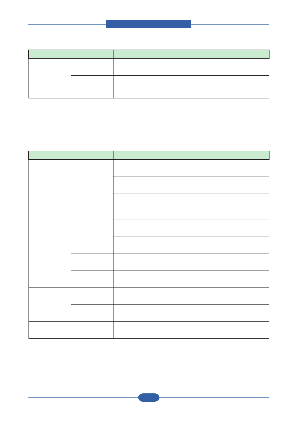
2.2.7 Consumables(CRU)
Item Description
No. of CRUs 9 (C/M/Y/K toner, C/M/Y/K imaging unit, Waste Toner Bottle)
K toner : CLX-K8380A
C toner : CLX-C8380A
M toner : CLX-M8380A
Y toner : CLX-Y8380A
K Imaging unit : CLX-R8380K
C Imaging unit : CLX-R8380C
M Imaging unit : CLX-R8380M
Y Imaging unit : CLX-R8380Y
Waste Toner Bottle : CLX-W8380A
Toner Black 20K pages A4/Letter, 5% Coverage
Color 15K pages A4/Letter, 5% Coverage
Key CRUM
Life detect T/C sensor & Dot Counter
Replace method User replaceable
"Imaging unit
(OPC+Deve)"
Yield 30K pages each CMYK Imaging unit
Key CRUM
Sensor Page Count & OPC Cycle count
Replace method User replaceable
Waste Toner Box Yield 48,000 images
Key N/A, Apply Full Sensor
Note : If you want to know more information for the consumables, consult the maintenance chapter.
Page 24
Product spec and feature
Service Manual
2-12
Samsung Electronics
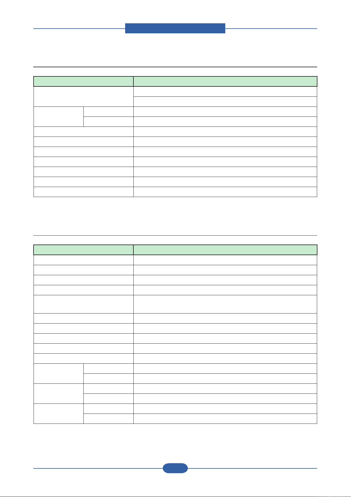
2.2.8 Consumables(FRU)
Item Description
No. of FRUs 8 (ITB, Fuser, T2 Roll, Pick-Up, ADF Rubber,
DADF Roller, MPF Rubber, MPF Roller)
ITB Yield 100,000 printing pages
Key CRUM
Fuser 100,000 printing pages
Transfer Roller(T2 Roller) 100,000 printing pages
Pick-up Roller 100,000 feeds
DADF rubber 50,000 feeds
DADF Roller 200,000 feeds
MPF rubber 50,000 feeds
MPF Roller 200,000 feeds
Note : If you want to know more information for the consumables, consult the maintenance chapter.
2.2.9 Reliability & Service
Item Description
Printing Volume (AMPV) 3,600 printing pages/month (40% Color, 60% Mono)
Max Monthly Duty 100,000 printing pages/month
MPBF 120,000 printing pages
MTTR 60 minutes
SET Life Cycle 1,000,000 printing pages or 5 years,
whichever comes rst (A4 size, IDC 5% coverage)
DADF Unit Life Time 500,000 feeds or 5 years, whichever comes rst
Platen Unit Life Time 75,000 scan or 5 years, whichever comes rst
Real-time Clock Yes
System-record Yes
Test Print Yes
RDC Comm. Mode Yes
Operation Yes
Temperature Operating 10~32 C (50~89.6F)
Storage -20~40 C (-4~104F)
Humidity Operating 20~80 % RH
Storage 10~90 % RH
Page 25

Product spec and feature
Service Manual
2-13
Samsung Electronics
2.2.10 Options
Item Model Name Remark
Memory Module CLP-MEM102 : 256 MB
CLP-MEM103 : 512 MB
Fax Option Kit SCX-FAX210(serial type)
SCX-FAX211(parallel type)
Optional Tray (SCF) SCX-S6555A 520 Sheet Feeder
Optional Tray
(HCF – High Capacity Feeder)
Stand SCX-DSK10T : Tall type
Finisher SCX-FIN10S
Staple Cartridge SCX-STP000 3x5000 staples per package
FDI(Foreign Device Interface) SCX-KIT11F
SmarThru Workow SCX-KIT11S
Jscribe SCX-KIT10J
Note : If you want to know more information for option units, consult the installaion chapter.
SCX-HCF100 2100 Sheet Feeder
SCX-DXK10S : Short type
Page 26
Product spec and feature
Service Manual
2-14
Samsung Electronics
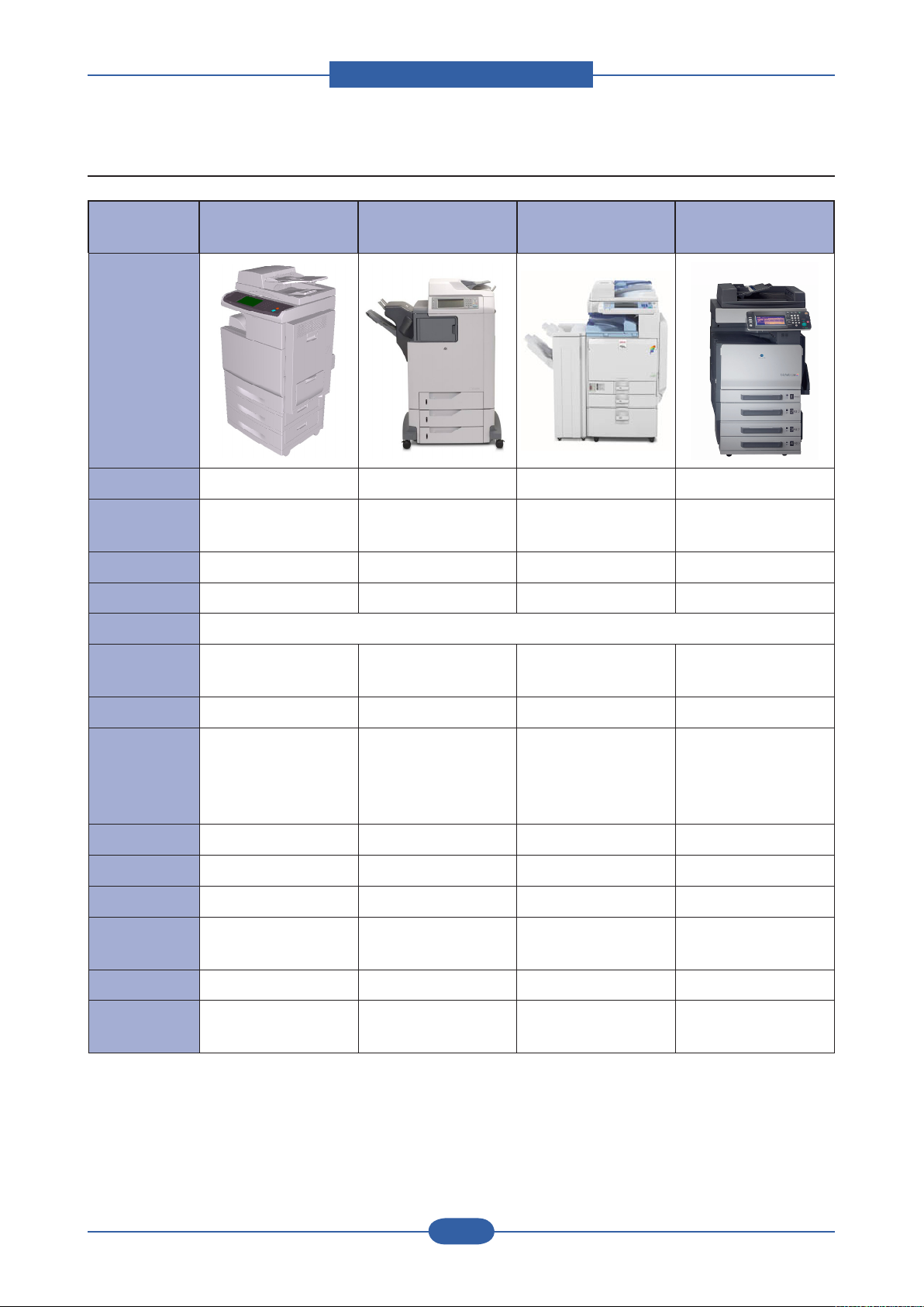
2.2.11 Model Comparison
Samsung
CLX-8380ND
Model
Type A4 Tendem A4 Tendem A3 Tendem A3 Tendem
Speed 38/38ppm(A4) 28/28ppm(A4)
FCOT(B/C) 14 sec / 14 sec 10sec / 12sec 6.7sec / 9.7sec 8.4sec / 11.7sec
Emulation PCL6, PS3, PDF1.4 PCL6, PS3, PDF1.4 PCL6, PS3, RPCS PCL6, PS3
Duplex Available (Std)
Scan Res(dpi)
/ Optical Max
600X600
/ 4800x4800
HP
LJ-4730
600X600 600X600 600X600
Acio MP C2500(A3)
Ricoh
24/24ppm(A4)
/ 12/12ppm(A3)
Konica Minolta
Bizhub C252(A3)
24/24ppm(A4)
/ 12/12ppm(A3)
ADF / Capa DADF /100sht ADF / 50sht DADF /50sht DADF(Opt) /50sht
Paper Capa/
CST
HDD 80GB Std 40GB Std 40GB Std 40GB Std
Memory (Max) 256MB / 512MB 448MB / 512MB 1GB 512MB
Interface USB 2.0 , N/W USB 2.0 , N/W USB 2.0 , N/W N/W
Rec. Color
AMVP
Mo. Duty Cycle 100K 175K 150K 75K
Toner /
Imaging unit
520sh + MP 100sh
HCF 2,100sh
Max 2,720 sh
3.6K 5K-9K 4.2K(Expected) 2.1K(Expected)
BK 20K, C15K / 30K B-12K, C-12K / - B-20K, C-15K / 80K
500sh x 3 + MP 100sh
Max 1,600sh
500sh x2 + MP 100sh
LCT 1,000sh x2
Max 3,100sh
500sh+MP
250sh+BP100sh
LCT 2,500sh
Max 3,350sh
B20K,C12K /
B70K,C45K
Page 27
Product spec and feature
Service Manual
2-15
Samsung Electronics
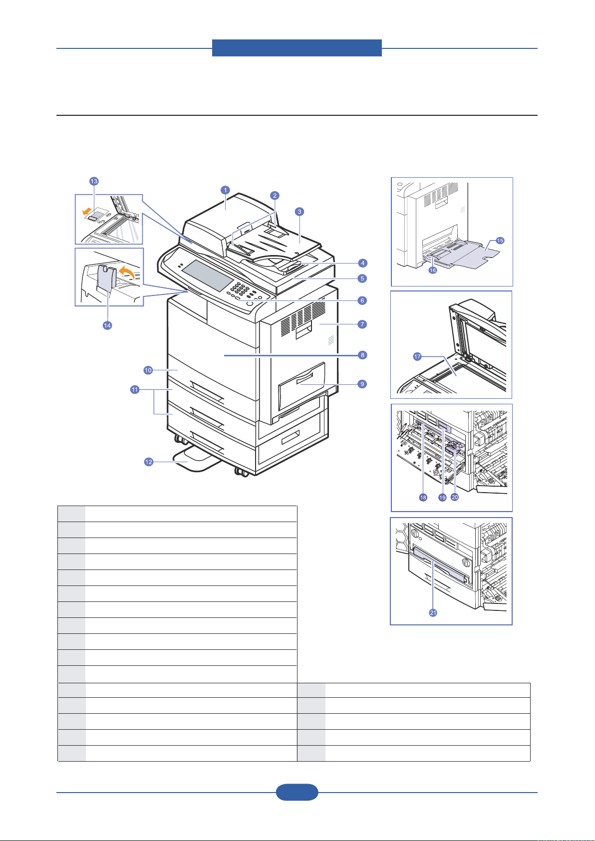
2.3 System Overview
•The symbol * is a mark for the optional device.
1
DADF cover
2
DADF doc ument width gui des
3
DADF doc ument in put tra y
4
DADF doc ument ou tput tra y
5
Scanner lid
6
Control p anel
7
Side cov er
8
Front cove r
9
Multi-purp ose tray
10
Tray 1
11
Optiona l tray
*
12
Stand
*
13
CCD Lock
14
Outp ut su pport
15
Multi -purpos e tra y extension
16
Multi -purpos e tra y paper w idth gu ides
17
Scann er gla ss
18
Transf er uni t
19
Toner c artr idge
20
Imaging u nit
21
Waste tone r cont ainer
■ Front view
Page 28
Product spec and feature
Service Manual
2-16
Samsung Electronics
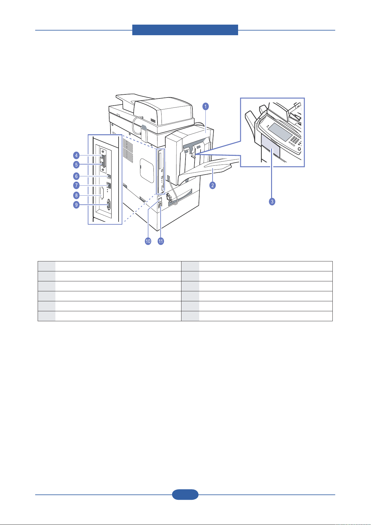
■ Rear view
•The symbol * is a mark for the optional device.
1
Finisher (Stacker & Stapler)
*
7
Network port
2
Finisher output tray (Stacker & Stapler)
*
8
Dummy for FDI (Foreign Device Interface)
*
3
Finisher cover (Stacker & Stapler)
*
9
15-pin Finisher connection (Stacker & Stapler)
*
4
Extension telephone socket (EXT)
*
10
Power switch
5
Telephone line socket
(LINE)
*
11
Power receptacle
6
USB port
12
USB memory port
Page 29
Product spec and feature
Service Manual
2-17
Samsung Electronics
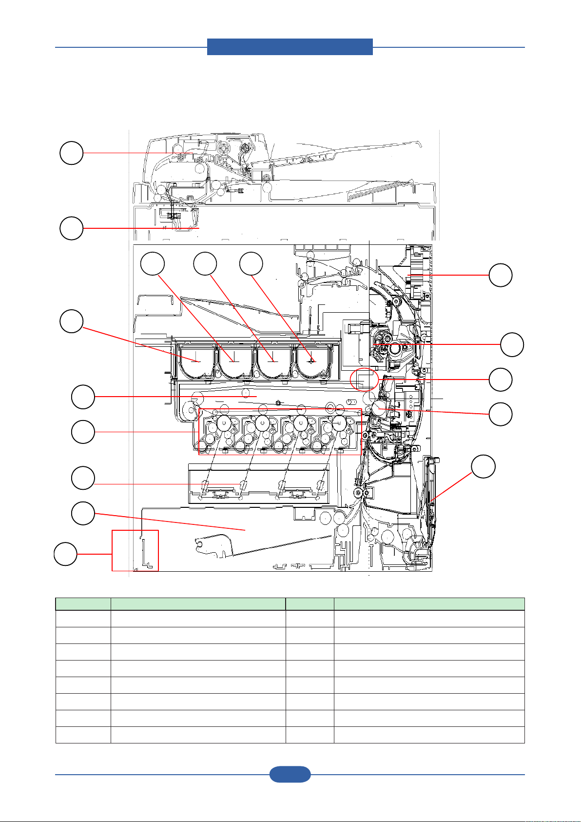
■ System Layout
1
2
3
4 5 6
12
13
7
8
9
10
16
11
15
14
1
2
3
4 5 6
12
13
7
8
9
10
16
11
15
14
No. Item No. Item
1 DADF Unit 9 LSU Unit
2 Scanner Unit 10 Standard tray
3 Toner-Cartridge (Y) 11 PSU (Power Supply Unit)
4 Toner-Cartridge (M) 12 Duplex Unit
5 Toner-Cartridge (C) 13 Fuser Unit
6 Toner-Cartridge (K) 14 ACR-Sensor
7 Cartridge-Transfer Unit 15 Roller Transfer
8 Imaging Unit 16 By-pass Feed Table
Page 30
Product spec and feature
Service Manual
2-18
Samsung Electronics
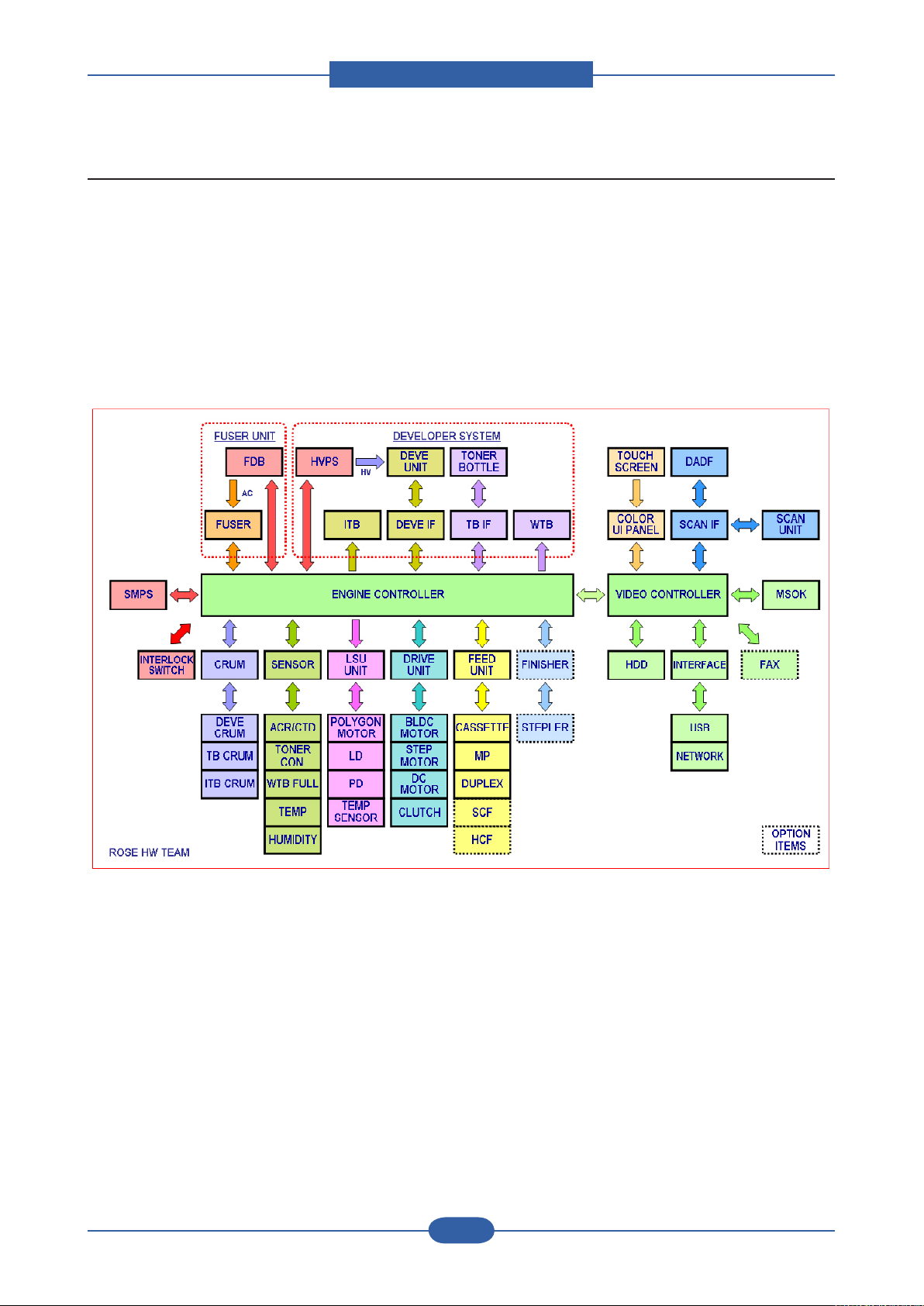
2.3.1 System Conguration
CLX-8380 series consists of Main Control Part, Engine Control Part, Operating Panel Part, Scanner Part,
Line Interface Part, Paper Feeding Part, Image Developing Part, Power Supply Part, Network Interface
Cards, and Optional DIMM (Dual-In-Memory Module) for Scan-To-Email.
The main controller uses a MIPS core and a MIPS-companion chip as main processors, which are dedicated
for printing & Fax functions and for driving several internal operating blocks through system programs stored
in Flash Memory. The engine controller has an independent ARM-based CPU and an engine control SoC,
which includes motor drivers, PWM drivers, LSU drivers, sensors, high-voltage drivers, and other driving
units for mechanical parts.
< System diagram >
Page 31

Product spec and feature
Service Manual
2-19
Samsung Electronics
2.3.2 H/W Conguration
LIU
DIMM
FINIS HER
I / F
VIDE O P B A
F DB
POWER INLET
S MPS
ENGINE PBA
BLDC
ITB
BLDC
BK
BLDC
OP C
BLDC
DE V E
(not shown)
BLDC
FUS E R
LIU
DIMM
FINIS HER
I / F
VIDE O P B A
F DB
POWER INLET
S MPS
ENGINE PBA
BLDC
ITB
BLDC
BK
BLDC
OP C
BLDC
DE V E
(not shown)
BLDC
FUS E R
OP_MAIN PBA
OP _ K E Y
OP
KEY
S UB
OP_MAIN PBA
OP _ K E Y
OP
KEY
S UB
■ Rear Side View
■ Operation Panel View ■ Left Side View
Page 32

Product spec and feature
Service Manual
2-20
Samsung Electronics
SCAN IF
connector
Engine B’d IF
connector
USB HOST
USB
Device
N/W connector
CIP5(IP)
HDD(SATA)
power connector
OPE main
connector
HDD(SATA) IF
connector
OPE USB I/F
connector
FDI
connector
DDR1 Option
DIMM Slot
CPU
SPGPxm
DDR1
BASE
DIMM
RM7965(MIPS)
LIU IF
Scanner
SDRAM
SCAN IF
connector
Engine B’d IF
connector
CIP5(IP)
DDR1 Option
DIMM Slot
CPU
SPGPxm
DDR1
BASE
DIMM
RM7965(MIPS)
LIU IF
Scanner
SDRAM
2.3.2.1 Video Controller
The Video Controller which is used to control printing and FAX functions comprises a MIPS core (RM7965),
a MIPS-companion video controller (SPGPxm), a PCI-interfaced image processor (CIP5) with SDRAMs,
DDR1 memory modules, and Flash memories. The Video controller includes an embedded network and
also provides USB host 2.0. The Scanner Part including DADF & CCD is connected to the Video controller
through the Scan Interface PBA.
Page 33

Product spec and feature
Service Manual
2-21
Samsung Electronics
■ Video Controller Power Distribution
Page 34

Product spec and feature
Service Manual
2-22
Samsung Electronics
EXIT
STEP MOT
BLDC
FUSER
ROM (1MB) SOC
(Jupiter4E)
MAIN IF
LSU C&K
LSU P-
MOTOR
LSU Y&M
HVPS1
CLUTCHS
SMPS1(24V)
COVER
OPEN
LOWER
ACR
BASE &
DUPLEX
SCF
BLDC BK
DEVE
CRUM
FINISHER
WASTE
MOT & LSU
CON
HVPS2
CRUM I/F
ASIC
(LPEC3)
BLDC OPC
BLDC
DEVE
MP
ASIC
(LPEC1)
SDRAM
(8MB)
T2 & BLDC
ITB
SMPS3
(SIGNAL)
T1 ENG
SENS
SMPS2(5V)
DUPLEX &
TOP SENS
FAN &
FUSER &
HUMI
COVER
OPEN
UPPER
THERMISTOR
EXIT SENS
LSU TEMP
REGI
SENSOR
Toner Motor
EXIT
ROM (1MB) SOC
(Jupiter4E)
MAIN IF
LSU C&K
LSU PMOTOR
LSU Y&M
HVPS1
CLUTCHS
SMPS1(24V)
COVER
OPEN
LOWER
ACR
BASE &
DUPLEX
SCF
BLDC BK
CRUM I/F
ASIC
(LPEC3)
BLDC OPC
MP
ASIC
(LPEC1)
SDRAM
(8MB)
T2 & BLDC
ITB
SMPS3
(SIGNAL)
T1 ENG
SENS
SMPS2(5V)
FAN &
FUSER &
HUMI
REGI
SENSOR
2.3.2.2 Engine Controller
The Engine Controller comprises an ARM-based CPU (J4E), engine control SoCs (LPEC1 & LPEC3),
SDRAM and Flash memories, and other drivers for mechanical elements. The Engine Controller manages an
Electro-photography system, controls the Video Data of printing images from Video Board to LSU, provides
PWMs and control signals for high voltages, adjusts temperature in the fusing system, and reads sensor
signals. The Engine Controller also includes control units for optional SCF and Finisher
Page 35

Product spec and feature
Service Manual
2-23
Samsung Electronics
■ Engine Controller Power Distribution
Page 36

Product spec and feature
Service Manual
2-24
Samsung Electronics
GATE
R_STACK
LENGTH DETECT/WIDTH
DOWNLOAD
EXIT
MOTOR
HYPER
(DEBUG)
REGI
SENSOR
DUPLEX/SCAN/
EXIT SENSOR
MAIN I/F
MPU:
S3F443FX
COVER
OPEN
SCAN
MOTOR
SCAN MOTOR
DRIVER
EXIT
MOTOR
MPU:
S3F443FX
2.3.2.3 DADF Board
The DADF PBA controls the DADF (Duplex Automatic Document Feeder) unit.
A DADF board controls 2 stepping motors, 2 clutches, 1 solenoid,10 sensors. By using CPU(S3F443FX )
having 80MHz Core Frequency. A DADF board supports customer to copy Max 100 sheets of documents
automatically. Also CLX-8380N’s DADF is serving
up to 65% of Duplex speed. And this happens to make one more paper path for high speed paper feeding.
Page 37

Product spec and feature
Service Manual
2-25
Samsung Electronics
■ DADF Block Diagram
Page 38

Product spec and feature
Service Manual
2-26
Samsung Electronics
DDR MEMORY
(64MB)
Main IF (USB)
LCD Interface
Main IF (power)
OPE Key sub
NOR FLASH
(32MB)
JTAG
Touch ScreenBack Light Unit
Debugger
OPE Key
MCU (S3C2413)
LCD Interface
OPE Key sub
NOR FLASH
(32MB)
2.3.2.4 OPE_Main Board
The OP_MAIN PBA controls the WVGA(800x600) 7” Color TFT LCD unit, and communicates with Video PBA
through USB1.1. The OP_MAIN PBA is connected with Key & Key_Sub PBAs which are used for scan and
fax functions.
The OP_MAIN PBA includes an ARM-based CPU (S3C2413C), a 32MB NOR Flash ROM, a 64MB DDR1
SDRAM memory, and a TSP control unit.
Page 39

Product spec and feature
Service Manual
2-27
Samsung Electronics
FuseVARISTOR
1
2
4
3
1
2
4
3
1
2
4
3
1
2
4
3
2.3.2.5 SMPS Board
SMPS( Switching Mode Power Supply ) Board supplies electric power to a Main Board and other boards
through a Main Controller by +5V,+24V from 110V/220V power input. It has safety protection modes for over
current and load.
SPECIFICATION
General Input/Output Voltage
1) AC 110V (90V ~ 135V)
2) AC 220V (180V ~ 270V)
3) Input Current: 5.0 [Arms]
4) Output Power: 335W / Max. 450W
DC 5V: 45W ~ 60W
DC 24V: 290W ~ 390W
• Connection
1 INPUT_AC (from Fuser Drive Board)
2 OUTPUT_5V1/2/3 (to Engine PBA)
3 OUTPUT_24V1/2/3/4 (to Engine PBA)
4 SMPS control (from Engine PBA)
Page 40

Product spec and feature
Service Manual
2-28
Samsung Electronics
◆
Input / Output connector
AC Input Connector( CN1 )
PIN ASSIGN PIN NO Description
1 AC_L
2 AC_N
Description PIN NO PIN ASSIGN PIN NO Description
Power +24V1 1 2 +24V1 Power
Power +24V1 3 4 GND 24V Ground
24V Ground GND 5 6 GND 24V Ground
Power +24V2 7 8 +24V2 Power
Power +24V2 9 10 GND 24V Ground
24V Ground GND 11 12 GND 24V Ground
Power +24V3 13 14 +24V3 Power
Power +24V3 15 16 GND 24V Ground
24V Ground GND 17 18 GND 24V Ground
Power +24V4 19 20 +24V4 Power
Power +24V4 21 22 GND 24V Ground
24V Ground GND 23 24 GND 24V Ground
Signal
(24V Remote
Sense)
RS24V 25 26 reserved
AC Input
DC Output Connector( CN2 )
Signal
(Reserved)
DC Output Connector( CN3 )
Description PIN NO PIN ASSIGN PIN NO Description
Power +5V1 1 2 +5V1 Power
Power +5V1 3 4 GND 5V Ground
5V Ground GND 5 6 GND 5V Ground
Power +5V2 7 8 +5V2 Power
Power +5V2 9 10 GND 5V Ground
5V Ground GND 11 12 GND 5V Ground
Power +5V3 13 14 +5V3 Power
Power +5V3 15 16 GND 5V Ground
5V Ground GND 17 18 GND 5V Ground
Signal
(5V Remote
Sense)
RS5V 19 20 Standby
(Standby Mode)
Signal
Page 41

Product spec and feature
Service Manual
2-29
Samsung Electronics
5
1
6
4
3
2
7
5
1
6
4
3
2
7
2.3.2.6 HVPS Board
CLX-8380 series has two HVPS( High Voltage Power Supply).
HVPS (High Voltage Power Supply) Unit is divided to Two PBAs, and generates 15 high-voltage channels
which includes T1(4), T2, MHV(4), DEVE(4), FB, and SP.
HVPS_L (High Voltage Power Supply_Large) supplies High Voltage power to Drum-cartridge (Charger),
ITB, T2-roller (T2-Unit).
• Connection
1 T1_Y/M/C/K (to ITB)
2 HVPS_L/S connection (to HVPS_S)
3 HVPS1 (from Engine PBA)
4 HVPS2 (from Engine PBA)
5 MHV_AC_Y/M (to Drum-cartridge)
6 MHV_AC_C/K (to Drum-cartridge)
7 T2 (to T2_Unit)
Page 42

Product spec and feature
Service Manual
2-30
Samsung Electronics
Saw-plate (to T2 Unit)Fuser-bias (to Fuser)
DEVE_Y/M/C/K (to Drum-cartridge)
HVPS_L/S_ connection (from HVPS_L)
HVPS_S (High Voltage Power Supply_Small) supplies High Voltage power to Drum-cartridge (Developer),
Fuser, Saw-plate (T2-Unit).
• Specication
Channel AC/DC No. Type Control
MHV
DC-
Constant-V PWM Duty
4
Rated
Load
250 pF
Output
-700 V 0 ~ -1800 V
Output
Range
Load
Range
0.1~3 mA
AC - PWM Duty 1.6 KVpp 1.0 ~ 3.2 Vpp
DEVE DC- 4 Constant-V PWM Duty 400 MΩ -500 V 0 ~ -800 V 0 ~ 30 uA
T1 DC+ 4 Constant-I PWM Duty 90 MΩ 14 uA 0 ~ 40 uA 0 ~ 3.5 KV
T2
DC+
Constant-I PWM Duty 100 MΩ 30 uA 0 ~ 50 uA 0 ~ 6.5 KV
1
DC- Constant-V Volume 80 MΩ -1300 V - 0 ~ 20 uA
Saw Plate DC- 1 Constant-V PWM Duty NO -1000 V 0 ~ -2.4 KV 0 ~ 40 uA
Fuser Bias DC+ 1 Constant-V PWM Duty NO 1000 V 0 ~ 1.5 KV 0 ~ 20 uA
• Constant current outputs in T1/T2 channels.
• Individual T1 channels for each color.
• Alternative DC +/- outputs between image & non-image periods in T2.
• AC + DC MHV Bias.
• Rated loads in all channels could be change according to the environmental conditions.
• All output channels can be adjusted by using volume control components.
Page 43

Product spec and feature
Service Manual
2-31
Samsung Electronics
2
1
4
3
FUSEVARISTOR PHOTO TRAIC
HEAT SINK
2
1
4
3
2.3.2.7 Fuser Drive Board
The FDB (Fuser Drive Board) controls 2 halogen lamps in the fuser unit using control signals which are
provided from the ENGINE PBA and supplies AC power to the SMPS. Both V1/V2 FDBs provide max.
1500W output power.
When the phase signal of AC Power goes to zero, the FDB sends a zero-crossing detect signal to the
ENGINE PBA. The zero-crossing output consists an open-collector node.
• Connection
1 INLET AC
2 FUSER CONTROL (from Main board)
3 FUSER AC (to Fuser lamp)
4 SMPS AC ( to SMPS)
• Specication
V1 V2
Input Voltage
(Range)
Input Current 20A 10A
Output Power Max. 1500W Max. 1500W
AC 110V
(90 ~ 135V)
Phase Detect Zero-Crossing Detect
(Open Collector Output)
Protection Relay Control Signal
AC 220V
(180 ~ 270V)
Page 44

Product spec and feature
Service Manual
2-32
Samsung Electronics
Finisher
Printer
# TxD
# RxD
Interface Cable
Connector 3Ways
D-Sub 15P. Female
10
11
12
13
14
15
# FIN_DETECT
# nFIN_RESET
+5V
N.C.
+3.3V
+24V
+24V
+24V
RxD #
TxD #
FIN_DETECT #
nFIN_RESET #
+5V
N.C.
+3.3V
+24V
+24V
+24V
GND(3.3/5V Power)
GND(3.3/5V Power)
GND(24V Power)
GND(24V Power)
FG(Case)
1
2
3
4
5
6
7
8
9
1
2
3
4
5
6
7
8
9
10
11
12
13
14
15
Connector 3Ways
D-Sub 15P. Male
# : TTL Level (3.3V )
GND(24V Power)
GND(3.3/5V Power)
GND(3.3/5V Power)
GND(24V Power)
GND(24V Power)
GND(24V Power)
FG(Case)
2.3.2.8 Finisher Board
A Finisher PBA is a Finisher controlling in CLX-8380N for option. It also consists one controller(S3F443FX),
two motor drive IC and LPEC1 for expandable I/O IC to control a nisher through UART communication with
a Main controller.
Page 45

Product spec and feature
Service Manual
2-33
Samsung Electronics
2.3.2.9 SCF/HCF PBA
A SCF PBA is a option cassette controlling in CLX-8380N. Max. 2 cassettes are connected on a purpose of
feeding paper. It consists one controller(S3F443FX) and two motor drive IC to control feeding timing through
Uart communication with a Main controller.
This PBA is also used in HCF. Key function is same with SCF and HCF & SCF can be able to be composed
together.
No. Signal Name Direction Active Level Description
1 24V POWER - +24V Power
2 3.3V POWER - +3.3V Power
3 GND POWER - Signal Ground
4 TxD OUT - Data Transmission
5 RxD IN - Data Receive
6 nBUSY OUT LOW SCF TxD Line Busy
7 nCMDREQ OUT LOW Command Request
8 Reserved1 I/O LOW Reserved
9 Reserved2 I/O LOW Reserved
Page 46

Product spec and feature
Service Manual
2-34
Samsung Electronics
2.3.2.10 FAX Board
• Specications
- LINE CONNECTION: PSTN or PABX (RJ-11)
- Compatibility: ITU-T G3, Super G3
- Communication System: PSTN/PABX
- Modem Speed: 33.6Kbps
- TX Speed: 3 sec
* Standard Resolution, MMR, 33,6Kbps
* Phase “C” by ITU-T No.1 Chart in Memory transmission with ECM
- Scan Speed
Platen -> 2 sec / A4
ADF -> 5.5 sec / A4
* Scan time: 2 sec/A4 @ 203x98dpi
* Scan setup time : 3.5 sec
- Receive Mode: Fax, TEL, ANS/FAX
- Compression: MH/MR/MMR/JBIG/JPEG
- ECM: Yes
- Resolution Std: 203*98dpi
Fine: 203*196dpi
S.Fine: 203x392dpi, 300*300dpi, 406x392dpi
- Contrast: Adsustable 5 levels
- Fax Memory: 32MB (in HDD)
Page 47

Product spec and feature
Service Manual
2-35
Samsung Electronics
• Serial & Parallel Types
How to connect a serial fax rst.
1) connect a line cord into Line RJ11.
2) Connect 2’nd phone by 4 line cord.
How to connect Parallel Fax
1) Connect a line cord into Line RJ11.
2) Just connect a phone to External RJ11.
Page 48

Product spec and feature
Service Manual
2-36
Samsung Electronics
2.3.2.11 Other PBAs
DEVE CRUM PBA
Finisher IF PBA
ERASER_LAMP_PBA
SCAN_IF_PBA
Page 49

Product spec and feature
Service Manual
2-37
Samsung Electronics
HCF HCF
2.3.3 Mechanic Conguration
2.3.3.1 Feeding Section
1) Cassette
It stores and automatically feeds print paper.
Pick-up Roller picks up paper, controls drive, feeds paper, removes static electricity, and so on.
> Spec.
* Feeding Method : Cassette Type
* Feeding Standard : Center Loading
* Feeding Capacity : Cassette 520 Sheets
(75g/ , 20lb Paper Standard) Manual Feeder
* Paper Detecting Sensor : Photo Sensor
(Empty, Registration, Exit)
* Paper Size : Legal, Letter, A4
2) SCF (Second Cassette Feeder ) / HCF ( High Capacity Feeder)
This additionally stores and automatically feeds printing paper. Its function is the same as the FCT (First
Cassette Tray)
> Spec.
* Paper Direction : FISO (Front-in, Side-Out)
* Cassette Type : A4, Ltr
* Paper Discharge : Separation Claw
* Capacity
SCF : 500 Sheets (Standard paper 75mg/m2 20lb)
HCF : 2100 Sheets (Standard paper 75mg/m2 20lb)
* Paper Size : A4, Letter
* Paper Weight (average) : 60~90g/ (16~24lbs)
* Paper Type : General Printing Paper
* Additional Function : Paper Empty Sensor
Paper Registration Sensor
Paper Exit Sensor
Page 50

Product spec and feature
Service Manual
2-38
Samsung Electronics
Duplex Motor
Fuser Motor
Exit Motor
Duplex Motor
Fuser Motor
Exit Motor
BK Motor
Main Motor
Color OPC Motor
Color DEVE Motor
BK Motor
Main Motor
Color OPC Motor
Color DEVE Motor
Toner Supply Motor
(4EA)
Toner Supply Motor
(4EA)
2.3.3.2 Drive Unit
There are many motors in this machine. Each motor is used for image process.
- Main Motor is for Paper path( Pick-up, Feed, Registration and MPF) and ITB.
- BK Motor is for Black OPC and Black DEVE
- Color OPC Motor is for Color OPC rotation (Yellow, Magenta, Cyan)
- Color DEVE Motor is for Color DEVE (Yellow, Magenta, Cyan)
- Fuser Motor is for Fuser and Exit roller
- Duplex Motor is for Duplex feeding
- Exit Motor is for stable stacking
- Toner Supply Motor is for toner supply
Page 51

Product spec and feature
Service Manual
2-39
Samsung Electronics
OPC Drum
Photo Diode
LD Driver circit
Protector panel
LD(Laser Diode)
Polygon Mirror
Polygon Motor
Motor Driver
KCMY KCMY KCMY
2.3.3.3 LSU ( Laser scanning unit )
LSU consists of LD(Laser Diode) and polygon motor control. For realizing Color Image, it is controled by
4 LD. When the controller generate the printing signal, LD will turn on and Polygon motor starts.If the
receiving part in LSU detect the beam , Hsync is generated. When the rotation of polygon motor is steady, it
is time of LSU ready status for printing. If either of two condition is not satised, LSU error is expected.
Page 52

Product spec and feature
Service Manual
2-40
Samsung Electronics
2.3.3.4 Fuser Unit
This unit consists of IH-HEAT ROLLER, Thermostats and a Thermistor. It melts and fuses the toner,
transferred by the transfer roller onto the paper, by applying pressure and high temperature to complete
printing job.
- Fusing Type : [Dual Lamp Heating, 700W/500W]
- Heat Roller :[ø18 ]
- Pressure Roller : [ø29 electrically conductive]
- Thermistor – Temperature Detecting Sensor
contact thermistor 2EA
- Thermostat – Overheat Protection Device
- Fuser Bias : 700V(HH), 500V(LL,NN)on the P/R tube
①
Thermostat
When a heat lamp is overheated, a Thermostat cuts off the main power to prevent over-heating.
- Non-Cotact type Thermostat
②
Heat roller & Belt
The heat roller & Belt transfers the heat from the lamp to apply a heat on the paper. The surface of belt
is coated with PFA, so toner does not stick to the surface.
③
Pressure roller
A pressure roller mounted under a heat roller is made of a silicon resin, and the surface also is coated with
Teon. When a paper passes between a heat roller and a pressure roller, toner adheres to the surface of
a paper permanently.
Page 53

Product spec and feature
Service Manual
2-41
Samsung Electronics
- Fuser Error
OPEN Heat LOW Heat OVER Heat
Warm-Up Less than 60℃
at more than 20
seconds
- Less than Warm Up Ref.
Temp-10℃ & for more than 20
seconds in Warm Up end time
Higher than 230℃(240℃) &For
continuous 30 seconds (5 sec)
(Not checking in case that motor
start temp(100℃) is not arrived)In case that the tempature is
not rising for 6 sec (Check at
WarmUp Ref Temp-30℃)
Stand-Byor
Recoverable
Error State for
Over Heat only
Printing N/A Less than Printing Ref. Temp-
N/A Less than Stand-By Ref. Temp-
40℃ & For more than 10
seconds
20℃ & For more than 10
- Higher than 230℃(240℃) & For
continuous 30 seconds(5 sec)
- StandBy Ref Temp+10℃& for
more than 3 min.
- Higher than 220℃(230℃) & For
continuous 20 seconds(3 sec)
seconds.
Power Save N/A N/A - Higher than 220℃(230℃) & For
continuous 20 seconds(3 sec)
- StandBy Ref Temp+10℃& for
more than 3 min.
Low Power N/A N/A - Higher than 220℃(230℃) & For
continuous 20 seconds(3 sec)
- StandBy Ref Temp+10℃& for
more than 3 min.
Other N/A N/A Higher than 220℃(230℃) & For
continuous 20 seconds(3 sec)
Page 54

Product spec and feature
Service Manual
2-42
Samsung Electronics
2.3.3.5 Scanner
2.3.3.5.1 Scanning Technology
1) Color Separation : Single-Pass color separation
Color separation is done with transmissive color lters put over the CCD elements themselves as part of
CCD manufacturing process. The CCD used in CLX-8380ND Series has three rows of imaging elements.
Each row has a color lter directly over the CCD elements, one row red, one green, and one blue.
2) Image Signal Input :
The output signal of CCD is designed for being ADC in S4L9335X through Bypass-Cap, and then
processing through the Signal which is dened between S4L9335X and CIP4.
It uses CDS (Correlated Double Sampling) which implement double Sampling for black level and image by
using signal of CIP4E, when AFE receives each pixels.
3) Image Processor :
It reads pixel data of CCD (Charge Coupled Device) by 600dpi Line, and in accordance with the mode set
from CIP4, said data is experiencing Error Diffusion Algorithm in mode or stored at Scan Buffer through
DMA without Halftoning Algorithm in PC Scan mode. At this time, both above modes conduct processing
after Shading Correction and Gamma Correction.
4) Optical System: Lens Reduction type All-In-One( Scanning Lamp + Lens + CCD Image sensor)
5) Light Source : Xenon Lamp
6) Scanning method
- Platen : Optical Moving
- DADF: Document Moving
Page 55

Product spec and feature
Service Manual
2-43
Samsung Electronics
2.3.3.5.2 Scanning Area
Effective Scanning width
Effective Scanning length
a
b
c d
Effective Scanning width
Effective Scanning length
a
b
c d
Maximum Document Width : 216mm
Effective Scanning Width: 208mm
Minimum Scan Width : 1” (25.4mm)
Minimum Scan Length : 1” (25.4mm)
a b c d
2mm ± 2mm 2mm ± 2mm 3mm ± 1mm 3mm ± 1mm
2.3.3.5.3 Source Document Specication (DADF)
The machine with this feature scans both sides of a paper.
• Spec
Capacity : Up to 50 sheets 75 g/m²
Copy speed : simplex 38cpm(LTR)/ duplex 25cpm(LTR)
Document Size : Width : 148 to 216 mm
Length : 145 to 356 mm for single page scan
Document Size Sensing Yes Extendible tray for long documents Yes
Adjustable Paper Guide Yes DADF Ready Indicator None
Labels w/graphics None Book copying with DADF open Yes
Wear out items (rolls) easily
replaceable w/o tools
145 to 400 mm for multi pages scan
No Wear out items (rolls) should be
serviced.
DADF Pad &
Feed Roller
Page 56

Product spec and feature
Service Manual
2-44
Samsung Electronics
• Layout
ⓙ
a
b
c
d
e
f
g
h
j
i
k
ⓙ
a
b
c
d
e
f
g
h
j
i
k
INDEX Description Qty Remark
MOTOR 2
ELECTRONIC CLUTCH 2
SOLENOID 1
PHOTO SENSOR 7 To detect Paper size
GATE 2
3 steps GATE 1
Document Path
SIMPLEX
DUPLEX
ⓐ → ⓑ → ⓒ → ⓓ → ⓔ
ⓐ → ⓑ → ⓒ → ⓕ → ⓖ → ⓗ → ⓒ → ⓘ → ⓙ → ⓚ→ ⓔ
Page 57

Product spec and feature
Service Manual
2-45
Samsung Electronics
2.3.3.6 Sensor
⑨ Power Low Sensor
⑦ Cassette Detect
⑤ Paper Empty Sensor
⑩ MPF Empty Sensor
①Bin Full Sensor
④ Duplex Jam
⑥ Duplex Ready
③ Exit Sensor
⑧ Paper Limit
② Regi Sensor
⑨ Power Low Sensor
⑦ Cassette Detect
⑤ Paper Empty Sensor
⑩ MPF Empty Sensor
①Bin Full Sensor
④ Duplex Jam
⑥ Duplex Ready
③ Exit Sensor
⑧ Paper Limit
② Regi Sensor
■ DESCRIPTION
①
Bin Full Sensor : Check overowing of Paper on Stacker
②
Regi Sensor : Two Regi Sensor for checking precise paper position
③
Exit Sensor : Check paper position on Fuser
④
Duplex Jam : Check paper position on Duplex path1
⑤
Paper Empty Sensor : Check Paper empty on a cassette
⑥
Duplex Ready : Check paper ready on Duplex path
⑦
Cassette Detect : Check cassette insertion
⑧
Paper Limit : Check raising paper up to feeding position
⑨
Paper Low Sensor : Check the number of paper below 100 pages
⑩
MPF Empty Sensor : Check paper empty on MPF
Page 58

Product spec and feature
Service Manual
2-46
Samsung Electronics
17
6
22
7
8
9
10
12
11
13
45
21
33/34/35/36
37/38/39/40
27
23
18/19
28
30
3
41/42/43/44
40
24/25/26
29
31
2
14/15/16
4
1 5
20
32
48
51
50
57
56
54
55
46/47
53
52
49
17
6
22
7
8
9
10
12
11
13
45
21
33/34/35/36
37/38/39/40
27
23
18/19
28
30
3
41/42/43/44
40
24/25/26
29
31
2
14/15/16
4
1 5
20
32
48
51
50
57
56
54
55
46/47
53
52
49
2.3.3.7 Sensor ( Expansion)
Page 59

Product spec and feature
Service Manual
2-47
Samsung Electronics
1 CASSETTE_DETECT
2 PAPER_NEAR_END
3 PAPER_UP_LIMIT
4 CASSETTE_EMPTY
5 MP_EMPTY
6 SENS_DUPLEX_JAM
7 SENS_FEED
8 SENS_TOP
9 SENS_REGI
10 SENS_PAPER_EXIT
11 SENS_DUPLEX_READY
12 OUTBIN_FULL
13 FINISHER_DETECT
14/15/16 PAPER_SIZE1(2/3)
17 THERMOSTAT
18/19 FUSER_THERM1(2)
20 OPC_BK_HOME
46/47 AUTO_PAPER_SIZE(2)
48 DADF_COVER_OPEN
49 CCD HOME SENSOR
50 SENS_DOC_DUPLEX
51 SENS_DOC_SCAN
52 SENS_DOC_LENGTH
53 SENS_DOC_EXIT
54 SENS_DOC_REGI
55 SENS_DOC_WIDTH
56 SENS_DOC_DETECT
57 SENS_DOC_GATE
58 SENS_GATE_HP
59 SENS_R_STACK
33/34/35/36 SENS_TC_Y(M/C/K)
37/38/39/40 CRUM_DEVE_Y(M/C/K)
41/42/43/44 CRUM_TB_Y(M/C/K)
45 CRUM_ITB
21 OPC_CR_HOME
22 SENS_T1_ENGAGE
23 SENS_T2_ENGAGE
24 SENS_CTD
25/26 SENS_ACD1(2)
27 SENS_LSU_CLN
28 INNER_TEMP
29 OUT_TEMP
30 SENS_HUMIDITY
31 WASTE_FULL
32 SENS_WTB_MOT
Page 60

Product spec and feature
M1
F1
F2
F3
F4
M2
M3
M4
M5
M6
M7
M8
M9
M10
M11
M12
M1
F1
F2
F3
F4
M2
M3
M4
M5
M6
M7
M8
M9
M10
M11
M12
2.3.3.8 Motor & Fan
The printer has ten motors and four fans. The gure below shows the locations of the motors and fans.
NAME FUNCTION NAME FUNCTION
M1 FUSER DRIVE BLDC MOTOR M9 LSU CLEANING DC MOTOR
M2 EXIT DRIVE STEPPING MOTOR M10 WASTE TONER BOTTLE DRIVE DC
M3 DUPLEX DRIVE STEPPING MOTOR M11 T1 ENGAGE DC MOTOR
M4 MAIN DRIVE BLDC MOTOR M12 T2 ENGAGE DC MOTOR
M5 BLACK OPC & DEVE DRIVE BLDC
MOTOR
M6 COLOR DEVE DRIVE BLDC MOTOR F2 FAN DC INVERTER : SMPS
M7 COLOR OPC DRIVE BLDC MOTOR F3 FAN DC : DUPLEX
M8 TONER SUPPLY DRIVE DC MOTOR F4 FAN DC : DUPLEX
Service Manual
F1 FAN-DC : HVPS
2-48
MOTOR
Samsung Electronics
Page 61

Maintenance and Disassembly
3. Maintenance and Disassembly
Introduction
To avoid print quality and paper feed problems resulting from worn parts and to maintain your
machine in top working condition the following items will need to be replaced after the specied
number of pages or when the life span of each item has expired.
3.1 Maintenance
3.1.1 Precautions on Maintenance
■ Replacing
- The fuser is very hot. So turn the printer off and wait until the printer to cool before replacing it.
- To avoid the print quality problems, do not touch the surface of rollers. (transfer roller, pick up roller, feed
roller, Cartridge transfer)
■ Cleaning
- Make sure the power cord is unplugged before the cleaning.
- Do not use ammable liquid cleaner or spray products for cleaning.
- Avoid making scratches while cleaning the parts.
- Avoid direct contact by hand on the Transfer Roller.
- Avoid exposing inner parts for a long duration of time.
- The surface of OPC Drum can be affected by direct light if exposed for a long time.
(1~2 minutes is enough time for cleaning)
- OPC surface must not be scratched.
Service Manual
3-1
Samsung Electronics
Page 62

Maintenance and Disassembly
Service Manual
3-2
Samsung Electronics
3.1.2 Check the consumables life
3.1.2.1 Printing Machine report
You can see the consumables life by printing a machine report.
1. Press the Machine setup button on the control panel.
2. Press Machine Status>the Machine Info tab>Print/Report
3. Select the report type, then the right side of the screen shows the list to print.
4. Select the list to print.
3.1.2.2 Monitoring the supplies life
If you want to view the consumables life, follow the next step.
1. Press the Machine Setup button on control panel.
2. Press the Machine Status
3. Scroll down to browse the entire supplies with list view the percentage remaining.
Page 63

Maintenance and Disassembly
Service Manual
3-3
Samsung Electronics
3.1.3 Consumables List(CRU)
Model Name Description Life Image
CLX-C8380A Toner Cartridge (Cyan) 15K Pages
CLX-M8380A Toner Cartridge (Magenta) 15K Pages
CLX-Y8380A Toner Cartridge (Yellow) 15K Pages
CLX-K8380A Toner Cartridge (Black) 20K Pages
CLX-R8380C Imaging Unit (Cyan) 30K Pages
CLX-R8380M Imaging Unit (Magenta) 30K Pages
CLX-R8380Y Imaging Unit (Yellow) 30K Pages
CLX-R8380K Imaging Unit (Black) 30K Pages
CLX-W8380A Waste toner container 48K Images
a. Declared yield value in accordance with ISO/IEC 19798.
b. Image counts are based on one color on each page. If you print documents in full color (Yellow, Magenta,
Cyan, Black), the image count will be added by 4 images.
Page 64

Maintenance and Disassembly
Service Manual
3-4
Samsung Electronics
3.1.4 Replacing the Consumables.
3.1.4.1 Replacing the toner cartridge
1. Turn the machine off, then wait a few minutes for
the machine to cool.
2. Open the side cover.
3. Open the front cover.
4. Pull the corresponding toner cartridge out from
the machine.
5. Remove the new toner cartridge from its bag.
6. Thoroughly roll the new cartridge ve or six times
to distribute the toner evenly inside the cartridge.
7. Pull out the protecting lm in the cartridges.
Page 65

Maintenance and Disassembly
Service Manual
3-5
Samsung Electronics
8. Hold the new toner cartridge by the handle and
slide the new toner cartridge in until it locks in
place.
3.1.4.2 Replacing the imaging unit
9. Close the front cover, then the side cover.
10. Make sure that the cover is securely latched
and then turn the machine on.
1. Turn the machine off, then wait a few minutes for
the machine to cool.
2. Open the side cover.
3. Open the front cover.
Page 66

Maintenance and Disassembly
Service Manual
3-6
Samsung Electronics
4. Pull the waste toner container out of the machine
using its handle.
5. Turn the imaging unit locking levers outwards to
release and open the inner cover.
7. Remove the new imaging unit from its bag.
8. Remove the paper protecting the surface of the
imaging unit.
9. Remove the cap, and carefully pull the seal
tapes out of the imaging unit.
10. Thoroughly shake the new imaging unit side to
side ve or six times.
6. Pull the used imaging unit out of the machine
using the handle on its bottom.
11. Labels inside the machine identify each imaging
unit’s position.
Holding the handles on the new imaging unit,
push the imaging unit until it locks in place.
Page 67

Maintenance and Disassembly
Service Manual
3-7
Samsung Electronics
12. Turn the imaging unit locking levers inwards
until it locks in place and close the inner cover.
3.1.4.3 Replacing the waste toner container
13. Insert the waste toner container into position
and then push it to make sure that it is rmly
seated in place.
14. Close the front cover, then the side cover.
15. Make sure that the cover is securely latched
and then turn the machine on.
1. Turn the machine off, then wait a few minutes for
the machine to cool.
2. Open the side cover.
3. Open the front cover.
4. Pull the waste toner container out of the machine
using its handle.
Page 68

Maintenance and Disassembly
Service Manual
3-8
Samsung Electronics
5. Remove the container’s cap from the container
as shown below, and use it to close the waste
toner container openings.
6. Take a new waste toner container out of its
package.
7. Insert the new container into position and then
push it to make sure that it is rmly seated in
place.
8. Close the front cover rmly.
9. Turn the machine on.
Page 69

Maintenance and Disassembly
Service Manual
3-9
Samsung Electronics
3.1.5 Maintenance Parts(FRU) List
Sec_Code Description Life Image
JC96-04601A
JC97-02934A
JC96-04867A (110V)
JC96-04868A (220V)
JC97-03097A
JC97-03099A
CARTRIDGE-
TRANSFER
MEA UNIT-TR
(Transfer roller Assy)
ELA UNIT-FUSER LV
ELA UNIT-FUSER HV
MEA-HOLDER ADF
RUBBER
MEA-PICK UP
(DADF pick up Assy)
100K
100K
100K
50K
200K
JC97-02260A
JC96-03533A ELA HOU-MP PICK UP 200K
JC97-03269A MEA UNIT-Exit Duplex 100K
JC97-02259A
MEA UNIT-HOLDER PAD
(MP tray pad Assy)
MEA UNIT-ROLLER PU
(Pick up roller)
50K
100K
Page 70

Maintenance and Disassembly
Service Manual
3-10
Samsung Electronics
Cartridge transfer
Transfer Roller
Fuser unit
DADF Pick up rollerDADF rubber Pad
MP tray rubber pad
MP tray feed roller
Pick up roller
■ Maintenance KIT List
Model code Parts Qty Life time Remark
CLX-V8380A Cartridge transfer
Transfer Roller
Fuser unit
Guide exit
Pick up roller
CLX-V8380A/SEE Cartridge transfer
Transfer Roller
Fuser unit
Guide exit
Pick up roller
CLX-V8380A/XAA Cartridge transfer
Transfer Roller
Fuser unit
Guide exit
Pick up roller
3.1.6 Location of Maintenance parts
1
1
1
1
3
1
1
1
1
3
1
1
1
1
3
100K Domestic
220V
100K Export
220V
100K Export
110V
Page 71

Maintenance and Disassembly
Service Manual
3-11
Samsung Electronics
3.1.7 Replacing the Maintenance parts
3.1.7.1 How to replace the Cartridge transfer
1.Open the front and side cover.
2. Take out the cartridge.
3. Take out the Cartridge transfer and replace the
new one.
Page 72

Maintenance and Disassembly
Service Manual
3-12
Samsung Electronics
3.1.7.2 How to replace the transfer roller
1. Open the side cover and then pull the guidepaper up in the direction of arrow.
2. Push the latch in the two directions and pull the
Transfer roller. And replace the new one.
3.1.7.3 How to replace the Fuser unit
1. Open the side cover. 2. Pull the Fuser unit by holding the green lever.
And replace the new one
Page 73

Maintenance and Disassembly
Service Manual
3-13
Samsung Electronics
3.1.7.4 How to replace the DADF pick up roller and rubber pad.
1. Open the DADF Cover.
2. Pull the bush in the direction of arrow. Then lift
the DADF pick up roller out.
3. Remove the rubber pad unit.
Page 74

Maintenance and Disassembly
Service Manual
3-14
Samsung Electronics
Roller-Pick Up
Roller-
Forward
Roller-Retard
Roller-Pick Up
Roller-
Forward
Roller-Retard
3.1.7.5 How to replace the Pick-up Roller
To remove the pick up roller, rst take out the cassette. After remove the cassette, you can see the pick up
roller in the inner. Pull the lever of pick up roller in the direction of arrow.
Page 75

Maintenance and Disassembly
Service Manual
3-15
Samsung Electronics
Bracket
Gear
Bracket
Gear
Bracket
Gear
Bracket
Gear
Hook
Left
Right
HookHookHook
Left
Right
3.1.7.6 How to replace the MP pad Unit and MP feed roller
Before MP unit disassembly, you must remove the covers, Deve Drive unit, side duplex unit etc.
(refer to 3.2.2 general disassembly procedure.)
1. Remove the 1 screw. Remove the Bracket and
3. Remove the 4 screws and 2 hooks and take out the MP Assy.
Gear as shown below.
2. Remove the MP pad unit after remove the 1
screw.
Page 76

Maintenance and Disassembly
Service Manual
3-16
Samsung Electronics
4. Done.
ELA HOU-MP
MEA UNIT-HOLDER PAD
ELA HOU-MP
MEA UNIT-HOLDER PAD
ELA HOU-MP
MEA UNIT-HOLDER PAD
ELA HOU-MP
MEA UNIT-HOLDER PAD
ELA HOU-MP
MEA UNIT-HOLDER PAD
ELA HOU-MP
MEA UNIT-HOLDER PAD
<How to replace the MP feed roller>
5. Release the harness from the holder.
6. Remove the spring from hook with some tools.
7. Remove the 4 screws from both side of MP unit.
8. Lift up the FRAME-MP TOP.
Page 77

Maintenance and Disassembly
Service Manual
3-17
Samsung Electronics
ELA- HOU MP PICK- UPELA- HOU MP PICK- UP
ELA- HOU MP PICK- UPELA- HOU MP PICK- UP
ELA- HOU MP PICK- UPELA- HOU MP PICK- UP
ELA- HOU MP PICK- UPELA- HOU MP PICK- UP
ELA- HOU MP PICK- UPELA- HOU MP PICK- UP
9. Done.
10. Remove the RING-E(2 EA) from both side of
FRAME-MP LOWER.
<How to reassemble MP feed roller>
12. Assemble the spring to ELA HOU-MP Pick up.
13. Fix the LATCH ARM F,R.
11. Replace the ELA-HOU MP PICK-UP with new
one.
Page 78

Maintenance and Disassembly
Service Manual
3-18
Samsung Electronics
14. When reassembling the FRAME-MP TOP,
assemble the STOPPER PAPER F,R to be in
the hole.
15. Check that LATCH ARM F,R assemble properly.
16. Assemble the SPRING as shown below.
17. Assemble in reverse order after this step.
Page 79

Maintenance and Disassembly
Service Manual
3-19
Samsung Electronics
1
2
Damper unit
1
2
Damper unit
121
2
Damper unit
3.1.7.7 How to replace the MEA UNIT-Exit Duplex
Before MEA UNIT-Exit Duplex disassembly, you must remove the covers, Deve drive unit.
(refer to 3.2.2 general disassembly procedure)
1. Remove the 1 connector and 2 screws. And remove the black bracket.
2. Pull the Side duplex Cover in the direction of arrow. And Release the damper unit securing the both side of
the Side duplex cover.
Page 80

Maintenance and Disassembly
Service Manual
3-20
Samsung Electronics
3. Remove the Side Duplex cover.
MEA UNIT-EXIT DUPLEXMEA UNIT-EXIT DUPLEX
4. Release the Exit Duplex Unit by removing the 4 hooks after remove 1 screw.
Page 81

Maintenance and Disassembly
Service Manual
3-21
Samsung Electronics
3.1.8 Cleaning the machine
To maintain print and scan quality, follow the cleaning procedures below
each time the toner cartridge is replaced or if print and scan quality problems occur.
Caution
• Cleaning the machine cabinet with cleaning materials that contain large amounts of alcohol, solvent, or
other strong substances can discolor or damage the cabinet.
• If your machine or its surrounding is contaminated with toner, we recommend you to use cloth or tissue
dampened with water to clean it. If you use a vacuum cleaner, toner blows in the air and might be harmful
to you.
Cleaning Items and Interval
Item Interval or When
Replacement consumable
(Toner Cartridges, Imaging Units, WTB )
Cleaning of Feed frame and Feed Rollers on the
paper-path
Cleaning of Document (Platen) glass The same copy area is dirty whenever making
Cleaning of Platen Cover (sheet-sponge)
Cleaning Feeder and PAD in the DADF Originals have black streaks or appear dirty after
Cleaning of LSU glass Streaks appear on copy sheet
Cleaning of Document glass for DADF
Cleaning of original guide plate in rear side of DADF
and DADF roller
Fasten the rest of the guide in the paper tray (Width
Guide and Length Guide)
Pick up a stack/tray of paper and fan it to remove
static cling
When displayed “Toner Empty” or “Replace Drum”
or “Waste Toner Full” .
Misfeeds or Jams occur frequently
copies.
Original cannot be cleanly scanned.
feeding them in the DADF.
Misfeeds or Jams occur frequently
Misfeeds or Jams occur frequently
Multi-feeds occur frequently
Page 82

Maintenance and Disassembly
Service Manual
3-22
Samsung Electronics
Cleaning the outside
Clean the machine cabinet with a soft lint-free cloth. You can dampen the cloth slightly with water, but be
careful not to let any water drip onto or into the machine.
Cleaning the inside
Clean every 100,000 sheets or every 6 months to maintain in good condition.
(When the Transfer Roller expires due to long usage.)
Clean in following order; Paper Path Parts, Transfer Roller, Toner Cartridge and Drum Cartridge in the Inner
Frame. Clean with Vacuum Cleaner and Dry rag or Soft cloth.
Cleaning Instructions
1. Paper Path Parts
- Cleaning Kit : Vacuum Cleaner and Dry rag or Soft cloth.
- Mal Affects : Dust particles from paper can be copied at worst making spot stains on the paper.
- Follow the display listed on the gure below.
2. Cleaning-Transfer Roller
- Cleaning Kit : Vacuum Cleaner and Dry rag or Soft cloth.
- Mal Affects : Dust particles from paper can be copied at worst making spot stains on the paper.
- When exchanging the Transfer Roller clean the area.
- Follow the display listed on the gure below.
3. Cleaning-Frame Inside
- Cleaning Kit : Vacuum Cleaner and Dry rag or Soft cloth.
- Mal Affects : The toner can leak and pollute the interior, affecting the print quality.
- Recommend an Engineer or highly experienced worker to clean.
Cleaning the scan unit
Keeping the scan unit clean helps ensure the best possible copies. We suggest that you clean the scan unit
at the start of each day and during the day, as needed.
1. Slightly dampen a soft lint-free cloth or paper towel with water.
2. Open the scanner lid.
3. Wipe the surface of the scanner glass and DADF glass until it is clean and dry.
4. Wipe the underside of the scanner lid until it is clean and dry.
5. Close the scanner lid.
Page 83

Maintenance and Disassembly
Service Manual
3-23
Samsung Electronics
Open the cover. Take out the cartridge.
Take out the Cartridge
Transfer.
Cover with a piece of paper
and lay it on a flat surface.
Clean the paper path parts.
Clean the paper path parts. Release the transfer roller.Clean the paper path parts.
1
2 3
11
2 33
4 644 66
7
9
8
77
99
88
555
Page 84

Maintenance and Disassembly
Service Manual
3-24
Samsung Electronics
Clean the transfer roller unit
parts.
Clean the transfer roller unit
parts.
Clean the Frame inside.
Reassemble the Cartridge
Transfer.
Reassemble the cartridge.
Reassemble the transfer
roller.
Clean the transfer roller unit
parts.
Clean the transfer roller unit
parts.
10 11 121010 1111 1212
1313 1414 15
1616
1717
Page 85

Maintenance and Disassembly
Service Manual
3-25
Samsung Electronics
3.2 Disassembly and Reassembly
3.2.1 General Precautions on Disassembly
When you disassemble and reassemble
components, you must use extreme caution. The
close proximity of cables to moving parts makes
proper routing a must.
If components are removed, any cables disturbed
by the procedure must be restored as close as
possible to their original positions. Before removing
any component from the machine, note the cable
routing that will be affected.
Whenever servicing the machine, you
must perform as follows:
1. Check to verify that documents are not stored in
memory.
2. Be sure to remove the toner cartridge before you
disassemble parts.
3. Unplug the power cord.
4. Use a at and clean surface.
5. Replace only with authorized components.
Releasing Plastic Latches
Many of the parts are held in place with plastic
latches. The latches break easily; release them
carefully.
To remove such parts, press the hook end of the
latch away from the part to which it is latched.
6. Do not force plastic-material components.
7. Make sure all components are in their proper
position.
Page 86

Maintenance and Disassembly
Service Manual
3-26
Samsung Electronics
3.2.1.1 Screws used in the printer
Part_Code Location Description Qty
6003-000282 ELA UNIT-LSU SCREW-TAPTITE;BH,+,-,B,M3,L8,ZPC(BLK),SWRCH18A,- 20
6003-000282 ELA UNIT-LD_Y SCREW-TAPTITE;BH,+,-,B,M3,L8,ZPC(BLK),SWRCH18A,- 2
6001-000130 ELA HOU-SIDE_DUPLEX SCREW-MACHINE;BH,+,M3,L6,ZPC(WHT),SWRCH18A,-,- 2
6003-000196 SCREW-TAPTITE;PWH,+,B,M3,L10,NI PLT,SWRCH18A 24
6003-000269 SCREW-TAPTITE;BH,+,-,S,M3,L6,ZPC(WHT),SWRCH18A,- 2
6002-000440 ELA HOU-DUPLEX SCREW-TAPPING;PWH,+,-,2,M3,L8,ZPC(BLK),SWRCH18A,- 4
6003-000196 SCREW-TAPTITE;PWH,+,B,M3,L10,NI PLT,SWRCH18A 5
6003-000264 MEA UNIT-TRAY SCREW-TAPTITE;PWH,+,-,B,M3,L6,ZPC(WHT),SWRCH18A,- 1
6003-000196 MEA UNIT-EXIT DUPLEX SCREW-TAPTITE;PWH,+,B,M3,L10,NI PLT,SWRCH18A 1
6003-000196 ELA UNIT-FRAME TOP SCREW-TAPTITE;PWH,+,B,M3,L10,NI PLT,SWRCH18A 9
6003-000269 SCREW-TAPTITE;BH,+,-,S,M3,L6,ZPC(WHT),SWRCH18A,- 2
6003-001256 SCREW-TAPTITE;BH,+,B,M4,L10,NI PLT,SWRCH18A 5
6009-001492 SCREW-HEX;HWH,+,M3,L8,NI PLT,SWRCH18A,S,RF 9
6003-000196 ELA UNIT-BASE FRAME SCREW-TAPTITE;PWH,+,B,M3,L10,NI PLT,SWRCH18A 13
6003-000269 SCREW-TAPTITE;BH,+,-,S,M3,L6,ZPC(WHT),SWRCH18A,- 11
6003-000301 SCREW-TAPTITE;BH,+,-,S,M4,L6,ZPC(WHT),SWRCH18A,- 1
6003-001256 SCREW-TAPTITE;BH,+,B,M4,L10,NI PLT,SWRCH18A 7
6009-001396 SCREW-SPECIAL;PH,+,-,M3,L10.3,ZPC(BLK),SWRCH18A,B
2
TITE,-
6003-000282 ELA UNIT-SIZE SENSOR SCREW-TAPTITE;BH,+,-,B,M3,L8,ZPC(BLK),SWRCH18A,- 2
6003-000266 ELA UNIT-CST SENSOR SCREW-TAPTITE;PWH,+,-,S,M3,L6,ZPC(WHT),SWRCH18A,- 2
6003-000269 ELA UNIT-BASE PLATE R SCREW-TAPTITE;BH,+,-,S,M3,L6,ZPC(WHT),SWRCH18A,- 13
6003-001474 SCREW-TAPTITE;BH,+,-,B,M3,L30,ZPC(WHT),SWRCH18A,- 3
6003-000196 ELA UNIT-PLATE UPPER SCREW-TAPTITE;PWH,+,B,M3,L10,NI PLT,SWRCH18A 3
6003-000269 SCREW-TAPTITE;BH,+,-,S,M3,L6,ZPC(WHT),SWRCH18A,- 6
6003-000196 ELA HOU-MP SCREW-TAPTITE;PWH,+,B,M3,L10,NI PLT,SWRCH18A 4
6003-000196 ELA UNIT-BASE RIGHT SCREW-TAPTITE;PWH,+,B,M3,L10,NI PLT,SWRCH18A 6
6003-000269 MEA UNIT-RETARD SCREW-TAPTITE;BH,+,-,S,M3,L6,ZPC(WHT),SWRCH18A,- 2
6003-000196 ELA UNIT-FRAME LOWER SCREW-TAPTITE;PWH,+,B,M3,L10,NI PLT,SWRCH18A 85
6003-000269 SCREW-TAPTITE;BH,+,-,S,M3,L6,ZPC(WHT),SWRCH18A,- 4
6003-000196 ELA UNIT-HV ITB SCREW-TAPTITE;PWH,+,B,M3,L10,NI PLT,SWRCH18A 4
6003-000269 ELA UNIT-WTB MOTOR SCREW-TAPTITE;BH,+,-,S,M3,L6,ZPC(WHT),SWRCH18A,- 2
6003-000269 ELA UNIT-HOLDER OPC SCREW-TAPTITE;BH,+,-,S,M3,L6,ZPC(WHT),SWRCH18A,- 11
6003-000196 ELA UNIT-HV TR SCREW-TAPTITE;PWH,+,B,M3,L10,NI PLT,SWRCH18A 2
6003-000196 ELA HOU-BOTTLE BASE SCREW-TAPTITE;PWH,+,B,M3,L10,NI PLT,SWRCH18A 13
6003-000196 ELA UNIT-HV DEVE SCREW-TAPTITE;PWH,+,B,M3,L10,NI PLT,SWRCH18A 8
Page 87

Maintenance and Disassembly
Service Manual
3-27
Samsung Electronics
Part_Code Location Description Qty
6003-000196 ELA HOU-REGISTRATION SCREW-TAPTITE;PWH,+,B,M3,L10,NI PLT,SWRCH18A 5
6003-000196 ELA HOU-GUIDE REGI SCREW-TAPTITE;PWH,+,B,M3,L10,NI PLT,SWRCH18A 6
6003-000196 MEA UNIT-F DR SCREW-TAPTITE;PWH,+,B,M3,L10,NI PLT,SWRCH18A 1
6003-000196 ELA UNIT-FRAME UPPER SCREW-TAPTITE;PWH,+,B,M3,L10,NI PLT,SWRCH18A 12
6003-000196 ELA HOU-GUIDE EXIT SCREW-TAPTITE;PWH,+,B,M3,L10,NI PLT,SWRCH18A 2
6003-000269 ELA UNIT-SUPPORT SCAN SCREW-TAPTITE;BH,+,-,S,M3,L6,ZPC(WHT),SWRCH18A,- 3
6009-001390 ELA UNIT-SCANNER SCREW-SPECIAL;SPECIAL,±,-,M3,L10,NI
1
PLT,SWRCH18A,B-TITE,D9, L13.5, DIME
6003-000196 ELA UNIT-PLATEN SCREW-TAPTITE;PWH,+,B,M3,L10,NI PLT,SWRCH18A 6
6003-000196 ELA UNIT-SCAN LOWER SCREW-TAPTITE;PWH,+,B,M3,L10,NI PLT,SWRCH18A 13
6003-000269 SCREW-TAPTITE;BH,+,-,S,M3,L6,ZPC(WHT),SWRCH18A,- 4
6003-001256 SCREW-TAPTITE;BH,+,B,M4,L10,NI PLT,SWRCH18A 14
6003-000282 ELA UNIT-CCDM HIGH SCREW-TAPTITE;BH,+,-,B,M3,L8,ZPC(BLK),SWRCH18A,- 10
6003-000282 MEA UNIT-COVER KHX SCREW-TAPTITE;BH,+,-,B,M3,L8,ZPC(BLK),SWRCH18A,- 3
6003-000269 ELA UNIT-SCAN MOTOR SCREW-TAPTITE;BH,+,-,S,M3,L6,ZPC(WHT),SWRCH18A,- 2
6002-000440 ELA UNIT-SCAN UPPER SCREW-TAPPING;PWH,+,-,2,M3,L8,ZPC(BLK),SWRCH18A,- 2
6003-000196 SCREW-TAPTITE;PWH,+,B,M3,L10,NI PLT,SWRCH18A 2
6003-000196 MEA UNIT-DUMMY UPPER SCREW-TAPTITE;PWH,+,B,M3,L10,NI PLT,SWRCH18A 1
6003-000196 ELA HOU-DADF SCREW-TAPTITE;PWH,+,B,M3,L10,NI PLT,SWRCH18A 7
6003-000269 SCREW-TAPTITE;BH,+,-,S,M3,L6,ZPC(WHT),SWRCH18A,- 8
6003-001256 SCREW-TAPTITE;BH,+,B,M4,L10,NI PLT,SWRCH18A 5
6003-000196 ELA HOU-COVER PLATEN SCREW-TAPTITE;PWH,+,B,M3,L10,NI PLT,SWRCH18A 14
6003-001324 SCREW-TAPTITE;BH,+,B,M4,L16,NI PLT,SWRCH18A,- 8
6003-000196 ELA HOU-COVER JAM SCREW-TAPTITE;PWH,+,B,M3,L10,NI PLT,SWRCH18A 1
6003-000196 ELA HOU-DADF SUB SCREW-TAPTITE;PWH,+,B,M3,L10,NI PLT,SWRCH18A 14
6003-000269 SCREW-TAPTITE;BH,+,-,S,M3,L6,ZPC(WHT),SWRCH18A,- 1
6003-000269 ELA HOU-DADF MOTOR SCREW-TAPTITE;BH,+,-,S,M3,L6,ZPC(WHT),SWRCH18A,- 4
6003-000269 ELA HOU-DUPLEX MOTOR SCREW-TAPTITE;BH,+,-,S,M3,L6,ZPC(WHT),SWRCH18A,- 2
6002-000440 ELA HOU-GUIDE SCAN SCREW-TAPPING;PWH,+,-,2,M3,L8,ZPC(BLK),SWRCH18A,- 2
6003-000196 SCREW-TAPTITE;PWH,+,B,M3,L10,NI PLT,SWRCH18A 7
6003-000269 SCREW-TAPTITE;BH,+,-,S,M3,L6,ZPC(WHT),SWRCH18A,- 1
6003-000196 ELA HOU-COVER OPEN SCREW-TAPTITE;PWH,+,B,M3,L10,NI PLT,SWRCH18A 5
6003-000196 MEA-EXIT SCREW-TAPTITE;PWH,+,B,M3,L10,NI PLT,SWRCH18A 2
6003-000196 MEA-GUIDE PICKUP SCREW-TAPTITE;PWH,+,B,M3,L10,NI PLT,SWRCH18A 4
6002-000440 MEA-TX STACKER SCREW-TAPPING;PWH,+,-,2,M3,L8,ZPC(BLK),SWRCH18A,- 2
6003-000196 SCREW-TAPTITE;PWH,+,B,M3,L10,NI PLT,SWRCH18A 3
6003-000269 ELA UNIT-DRIVE MAIN SCREW-TAPTITE;BH,+,-,S,M3,L6,ZPC(WHT),SWRCH18A,- 6
6003-000301 SCREW-TAPTITE;BH,+,-,S,M4,L6,ZPC(WHT),SWRCH18A,- 10
Page 88

Maintenance and Disassembly
Service Manual
3-28
Samsung Electronics
Part_Code Location Description Qty
6003-000269 ELA UNIT-DRIVE DEVE SCREW-TAPTITE;BH,+,-,S,M3,L6,ZPC(WHT),SWRCH18A,- 16
6003-000301 SCREW-TAPTITE;BH,+,-,S,M4,L6,ZPC(WHT),SWRCH18A,- 17
6003-000269 ELA UNIT-DRIVE FUSER SCREW-TAPTITE;BH,+,-,S,M3,L6,ZPC(WHT),SWRCH18A,- 4
6003-000301 SCREW-TAPTITE;BH,+,-,S,M4,L6,ZPC(WHT),SWRCH18A,- 4
6003-000282 CARTRIDGE-TRANSFER SCREW-TAPTITE;BH,+,-,B,M3,L8,ZPC(BLK),SWRCH18A,- 20
6003-000196 ELA UNIT-MAIN LINE SCREW-TAPTITE;PWH,+,B,M3,L10,NI PLT,SWRCH18A 68
6003-000269 SCREW-TAPTITE;BH,+,-,S,M3,L6,ZPC(WHT),SWRCH18A,- 44
6003-001256 SCREW-TAPTITE;BH,+,B,M4,L10,NI PLT,SWRCH18A 22
6009-001390 SCREW-SPECIAL;SPECIAL,±,-,M3,L10,NI
4
PLT,SWRCH18A,B-TITE,D9, L13.5, DIME
6009-001396 SCREW-SPECIAL;PH,+,-,M3,L10.3,ZPC(BLK),SWRCH18A,B
4
TITE,-
6003-000196 ELA HOU-EXIT SCREW-TAPTITE;PWH,+,B,M3,L10,NI PLT,SWRCH18A 15
6003-000269 SCREW-TAPTITE;BH,+,-,S,M3,L6,ZPC(WHT),SWRCH18A,- 2
6003-000196 ELA UNIT-SMPS UPPER SCREW-TAPTITE;PWH,+,B,M3,L10,NI PLT,SWRCH18A 1
6003-000269 SCREW-TAPTITE;BH,+,-,S,M3,L6,ZPC(WHT),SWRCH18A,- 2
6003-000196 ELA UNIT-HOLDER_HVPS SCREW-TAPTITE;PWH,+,B,M3,L10,NI PLT,SWRCH18A 2
6003-000269 ELA UNIT-SUPPORT REAR SCREW-TAPTITE;BH,+,-,S,M3,L6,ZPC(WHT),SWRCH18A,- 2
6003-000282 CARTRIDGE-DRUM Y KIT SCREW-TAPTITE;BH,+,-,B,M3,L8,ZPC(BLK),SWRCH18A,- 7
6001-000130 ELA HOU-DEVE UNIT SCREW-MACHINE;BH,+,M3,L6,ZPC(WHT),SWRCH18A,-,- 2
6003-000282 SCREW-TAPTITE;BH,+,-,B,M3,L8,ZPC(BLK),SWRCH18A,- 5
6006-001193 SCREW-MACHINE;PH,+,WSP,M3,10,ZPC(WHT),SWRCH18
2
A,-,WD8,TEMPERED
6003-000282 MEA UNIT-OPC CART SCREW-TAPTITE;BH,+,-,B,M3,L8,ZPC(BLK),SWRCH18A,- 2
6003-000282 CARTRIDGE-DRUM M KIT SCREW-TAPTITE;BH,+,-,B,M3,L8,ZPC(BLK),SWRCH18A,- 7
6001-000130 ELA HOU-DEVE UNIT SCREW-MACHINE;BH,+,M3,L6,ZPC(WHT),SWRCH18A,-,- 2
6003-000282 SCREW-TAPTITE;BH,+,-,B,M3,L8,ZPC(BLK),SWRCH18A,- 5
6006-001193 SCREW-MACHINE;PH,+,WSP,M3,10,ZPC(WHT),SWRCH18
A,-,WD8,TEMPERED
6003-000282 MEA UNIT-OPC CART SCREW-TAPTITE;BH,+,-,B,M3,L8,ZPC(BLK),SWRCH18A,- 2
6003-000282 CARTRIDGE-DRUM C KIT SCREW-TAPTITE;BH,+,-,B,M3,L8,ZPC(BLK),SWRCH18A,- 7
6001-000130 ELA HOU-DEVE UNIT SCREW-MACHINE;BH,+,M3,L6,ZPC(WHT),SWRCH18A,-,- 2
6003-000282 SCREW-TAPTITE;BH,+,-,B,M3,L8,ZPC(BLK),SWRCH18A,- 5
6006-001193 SCREW-MACHINE;PH,+,WSP,M3,10,ZPC(WHT),SWRCH18
A,-,WD8,TEMPERED
6003-000282 MEA UNIT-OPC CART SCREW-TAPTITE;BH,+,-,B,M3,L8,ZPC(BLK),SWRCH18A,- 2
6003-000282 CARTRIDGE-DRUM K KIT SCREW-TAPTITE;BH,+,-,B,M3,L8,ZPC(BLK),SWRCH18A,- 7
2
2
Page 89

Maintenance and Disassembly
Service Manual
3-29
Samsung Electronics
Part_Code Location Description Qty
6001-000130 ELA HOU-DEVE UNIT SCREW-MACHINE;BH,+,M3,L6,ZPC(WHT),SWRCH18A,-,- 2
6003-000282 SCREW-TAPTITE;BH,+,-,B,M3,L8,ZPC(BLK),SWRCH18A,- 5
6006-001193 SCREW-MACHINE;PH,+,WSP,M3,10,ZPC(WHT),SWRCH18
2
A,-,WD8,TEMPERED
6003-000282 MEA UNIT-OPC CART SCREW-TAPTITE;BH,+,-,B,M3,L8,ZPC(BLK),SWRCH18A,- 2
6003-000261 ELA UNIT-TONER K SCREW-TAPTITE;BH,+,-,B,M3,L6,ZPC(WHT),SWRCH18A,- 2
6003-000282 SCREW-TAPTITE;BH,+,-,B,M3,L8,ZPC(BLK),SWRCH18A,- 1
6003-000261 ELA UNIT-TONER Y SCREW-TAPTITE;BH,+,-,B,M3,L6,ZPC(WHT),SWRCH18A,- 2
6003-000282 SCREW-TAPTITE;BH,+,-,B,M3,L8,ZPC(BLK),SWRCH18A,- 2
6003-000261 ELA UNIT-TONER M SCREW-TAPTITE;BH,+,-,B,M3,L6,ZPC(WHT),SWRCH18A,- 2
6003-000282 SCREW-TAPTITE;BH,+,-,B,M3,L8,ZPC(BLK),SWRCH18A,- 2
6003-000261 ELA UNIT-TONER C SCREW-TAPTITE;BH,+,-,B,M3,L6,ZPC(WHT),SWRCH18A,- 2
6003-000282 SCREW-TAPTITE;BH,+,-,B,M3,L8,ZPC(BLK),SWRCH18A,- 2
6003-000196 ELA HOU-OPE SCREW-TAPTITE;PWH,+,B,M3,L10,NI PLT,SWRCH18A 10
6003-000269 SCREW-TAPTITE;BH,+,-,S,M3,L6,ZPC(WHT),SWRCH18A,- 4
6003-000196 ELA HOU-OPE COVER SCREW-TAPTITE;PWH,+,B,M3,L10,NI PLT,SWRCH18A 7
6002-000440 ELA UNIT-FUSER LV SCREW-TAPPING;PWH,+,-,2,M3,L8,ZPC(BLK),SWRCH18A,- 3
6003-000196 SCREW-TAPTITE;PWH,+,B,M3,L10,NI PLT,SWRCH18A 17
6003-000269 SCREW-TAPTITE;BH,+,-,S,M3,L6,ZPC(WHT),SWRCH18A,- 9
6003-001086 SCREW-TAPTITE;BH,+,-,B,M3,L12,ZPC(BLK),SWRCH18A,- 2
6002-000440 MEA UNIT-CASSETTE SCREW-TAPPING;PWH,+,-,2,M3,L8,ZPC(BLK),SWRCH18A,- 5
6003-000196 SCREW-TAPTITE;PWH,+,B,M3,L10,NI PLT,SWRCH18A 6
6006-001193 SCREW-MACHINE;PH,+,WSP,M3,10,ZPC(WHT),SWRCH18
1
A,-,WD8,TEMPERED
6002-000440 MEA UNIT-LIFTING GEAR SCREW-TAPPING;PWH,+,-,2,M3,L8,ZPC(BLK),SWRCH18A,- 2
6003-001001 MEA UNIT-COVER FRONT SCREW-TAPTITE;FH,+,B,M3,L8,ZPC(BLK),SWRCH18A 2
6002-000440 MEA UNIT-COVER INNER SCREW-TAPPING;PWH,+,-,2,M3,L8,ZPC(BLK),SWRCH18A,- 6
6003-000196 SCREW-TAPTITE;PWH,+,B,M3,L10,NI PLT,SWRCH18A 4
6002-000440 MEA UNIT-FRONT OPC SCREW-TAPPING;PWH,+,-,2,M3,L8,ZPC(BLK),SWRCH18A,- 30
6006-001078 SCREW-TAPTITE;PH,+,WSP,B,M3,L10,ZPC(WHT),SWRCH1
12
8A,-
Page 90

Maintenance and Disassembly
Service Manual
3-30
Samsung Electronics
3.2.2 General Disassembly
M3X10
M4X10
M3X10
M4X10
M3X10
M4X10
M3X10
M4X10
M3X10
M3X10
M3X10
M4X10
M3X10
M4X10
M3X10
M4X10
M3X10
M4X10
3.2.2.1 Cover
1. Remove the 10 screws from the rear of SET.
2. Remove the 4 screws from the left side of SET.
And remove the Cover Panel MFP.
4. Remove the Cover rear and the Cover rear
lower.
5. Remove the 2 screws and then remove the Unit
Cover Top.
3. Remove the COVER-PANEL MFP.
Note : In case of being installed the fax kit, remove the fax kit after
remove the 2 screws.
Page 91

Maintenance and Disassembly
Service Manual
3-31
Samsung Electronics
SIDE-DUPLEX COVER
COVER-FRONT
COVER-
SIDE LEFT
SIDE-DUPLEX COVER
COVER-FRONT
COVERSIDE LEFT
5. Open the Side Duplex Cover and the Front cover. And then remove the left side cover.
3.2.2.2 DADF
1. Remove one screw, and disassemble the cover.
2. Unplug the cable, and lift up the DADF from the
SET in the direction of arrow
3. Open the DADF cover, and remove the one
screw.
4. Lift up the stacker, and remove the two screws.
Page 92

Maintenance and Disassembly
Service Manual
3-32
Samsung Electronics
5. Remove the front/rear cover of the DADF.
6. Unplug the all harness from the DADF board.
8. Remove the 3 screws, and then remove the
DADF board.
9. Pull the bush in the direction of arrow. Then lift
the DADF pick up roller out.
7. Remove the 2 screws, and then remove the
harness holder.
10. Remove the DADF pad unit.
Page 93

Maintenance and Disassembly
Service Manual
3-33
Samsung Electronics
3.2.2.3 OPE
1. Remove the OPE cover. And remove the 3
screws.
2. Lift up the OPE assy as shown below, and
Unplug the connector. And release the OPE
assy from set.
3. Disconnect the 2 harness, 3 exible pcb, and
remove the 4 screws. And then remove the OPE
PBA.
4. To remove the LCD panel, remove the 10
screws. Take out the LCD panel after remove the
LCD panel shield.
Page 94

Maintenance and Disassembly
Service Manual
3-34
Samsung Electronics
3.2.2.4 Scan Ass’y
1
2
3
1
2
3
1. Remove the 2 screws from the Front dummy
cover and release it.
2. Remove the 4 screws from front-down side of
scan assy.
4. Lift up and release the Scan Assy.
Release the Scan upper from the Scan lower
5.
after remove the 6 screws (cap hole screw 3 EA)
3. Remove the 3 screws and all harness connected
to scan assy.
Page 95

Maintenance and Disassembly
Service Manual
3-35
Samsung Electronics
6. Release the Lever-locker from the scan upper
after remove the 2 screws.
7. To remove the CCD harness, rst remove the
sheet.
9. Remove the CCDM after remove the CCDM
belt.
10. Remove the Scan motor assy after remove the
4 screws.
8. Unplug the FFC cable and power cable.
11. To remove the CCD harness, remove the sheet.
Page 96

Maintenance and Disassembly
Service Manual
3-36
Samsung Electronics
M3X10
S3X6
M3X10
S3X6
12. Remove the screws and the harness from each
sensor.
13. When replacing the Belt, compress the spring.
3.2.2.5 Engine and Video controller
1. Unplug the all harness and remove the 4 screws
from Video controller. And release it.
2. Unplug the all harness and remove the 9 screws
from Engine controller. And release it.
Caution - When reassembling, be careful the
screw type.
Page 97

Maintenance and Disassembly
Service Manual
3-37
Samsung Electronics
3.2.2.6 SMPS and Fuser Drive board
1. Remove the 3 screws and 1 connector. Remove
the SMPS cover.
2. Unplug the all harness and remove the 4 screws
from FDB . And release it.
3. Remove the all harness from SMPS.
4. Remove the SMPS after remove the 8 screws.
Page 98

Maintenance and Disassembly
Service Manual
3-38
Samsung Electronics
3.2.2.7 Main Drive Unit
fixerfixerfixer
M3X10
S3X6
M3X10
S3X6
ELA UNIT-DRIVE MAINELA UNIT-DRIVE MAIN
1. Remove the 4 screws and remove the SMPS
cover.
2. Release the harness from the harness holder.
3. Remove the engine controller shield after
remove the 5 screws.
Caution - When reassembling, be careful the
screw type.
4. First, remove the 4 xer and remove the 2
screws. Release the part as shown below.
Page 99

Maintenance and Disassembly
Service Manual
3-39
Samsung Electronics
ELA UNIT-DRIVE MAINELA UNIT-DRIVE MAIN
5. Remove the 4 clutches and pull the harness
holder in the direction of arrow.
Note : When disassembling the main drive unit,
Don’t have to unplug the cluthc harness. If
you want to replace the clutches, refer to
the next page.
6. Remove the Main drive Unit after remove the 6
screws.
Page 100

Maintenance and Disassembly
Service Manual
3-40
Samsung Electronics
< How to replace the cluch >
1. Hold the harness with the nipper.
Caution - Don’t grip with force. It is easy to
disconnect.
※ Precautions
2. Unplug the harness as shown below.
1. When reassembling the 2 clutch below, check the
harness color.
There is the incuse on the shield. B/B means black/black
harness, G/B means gary/black harness.
2. When reassembing the cluches, check the cluch color.
The top clutch color is white. Others are black.
 Loading...