

SAMSUNG CL21M6WKX-XAO, CL21A11MQKXXAX Service Manual
COLOR TELEVISION RECEIVER
Chassis : K57A(N)
Model : CL21M6WKX/XAO
CL21A11MQKXXAX
COLOR TELEVISION RECEIVER CONTENTS
Precautions
Specifications and IC Data
Disassembly and Reassembly
Alignment and Adjustment
Troubleshooting
Exploded View and Parts List
Electrical Parts List
Block Diagram
Wiring Diagram
Schematic Diagrams
1.
2.
3.
4.
5.
6.
7.
8.
9.
10.
2-2 Samsung Electronics
2-2 IC Line Up
Specifications and IC Data
Table 2-1 IC Line-Up
Loc. No
IC201S
IC301
IC501
IC602
IC801S
IC802 KA7632
IC202
PC801S
PC802S
IC101
IC601
ICP01
Specification
SPM-464A
LA7845
TDA6108QJF
TDA7297
KA5Q1265R
M24C08
TCET1108 / LTV817B
LA7510
MSP-3425G-B8
VIPER12AD1P
Description
TDA9592 PS/NI, SPM-464A,64P
VERTICAL OUTPUT
RGB DRIVE AMP
SOUND-AMP (15W x 2CH)
POWER IC (STR)
CUSTOM REGULATOR (5V, 8V, 3.3V)
EEPROM
PHOTO COUPLER
IF DETECTOR-IC
Sound Processor
PWM CONTROCER-IC
Remark
Philips
Sanyo
Philips
Philips
FIAIR CHILD
FIAIR CHILD
TEMIC
Micronas
ICW01
ICG01
NJM2235D
4558
VIDEO Swiching-IC
OP AMP-IC

Alignment and Adjustments
Samsung Electronics 4-1
4. Alignment and Adjustments
4-1 Preadjustment
4-1-1 Factory Mode
1. Do not attempt these adjustments in the Video
Mode.
2. The Factory Mode adjustments are necessary
when either the EEPROM (IC202) or the CRT
is replaced.
3. Do not tamper with the “Adjustment” screen
of the Factory Mode menu. This screen is
intended only for factory use.
4-1-2 When EEPROM (IC202) Is Replaced
1. When IC202 is replaced all adjustment data
revert to initial values. It is necessary to
re-program this data.
2. After IC202 is replaced, warm up the TV for
10 seconds.
4-1-3 When CRT Is Replaced
1. Make the following adjustments AFTER setting up after setting up purity and convergence :
White Balance
Sub-Brightness
Vertical Center
Vertical Size
Horizontal Size
Fail Safe (This adjustment must be the last
step).
2. If the EEPROM or CRT is replaced and set SC
as 30(factory mode).
4-2 Factory/Service Mode
4-2-1 Procedure for the “Adjustment” Mode
1. This mode uses the standard remote control.
The Service Mode is activated by entering the
following remote-control sequence :
(1) DISPLAY → FACTORY.
(2) STAND-BY → MUTE → 1 → 8 → 2
→POWER ON.
2. The “SERVICE (FACTORY)” message will be
displayed. The Service Mode has four components: ADJUST, OPTION , G2-ADJUST and
RESET.
3. Access the Adjustment Mode by pressing the
“VOLUME” keys ( Up or Down). The adjustment parameters are listed in the accompanying table, and selected by pressing the CHANNEL keys ( , ).
4. Selection sequences for the all system:
DOWN or UP key:
SCT>SBT>BLR>BLB>RG>GG>BG>VSL>VS>
VA>HS>SC>CDL>STT>AKB>NDL>NSR>
SCBT>VOL>CAP>MVOL>RP00>RP01>
AGCS>OMD>SCL>PWL>MUS>AGC>
HPAR>HBOW>EWID>EPAR>EUCN>ELCN>
ETRP>VZ>SVM>VMA>SSP>PSNS>
DNSR>DSBT>DCDL>DBLR>DBLB>DSK
5. The VOLUME keys increase or decrease the
adjustment values (stored in the
non-volatile memory) when Adjustment Mode
is cancelled.
6. Cancel the Adjustment Mode by re-pressing
the “FACTORY” or “Power OFF” keys.
4-2-2 Main Adjustment Parameter
Alignment and Adjustments
4-2 Samsung Electronics
ONO SD F UN CT I ON R A N GE I NI TI AL D ATA SELECTION RE MARK
1
SCT Sub Cont rast 0 ~ 23
2
SBT Sub Bright nes s
3
BLR
4
BLB
Black Level offset R
Black Level offset B
0~23
0~63
0~63
13
32
32
ADJ
9
ADJ
ADJ
ADJ
5
RG Red Gain 0~63
6
GG Green Gai n 0 ~ 63
7
BG Bl ue Gai n 0 ~ 63
8
VSL Ver t ical S lope 0 ~ 63
9
VS Ver t ical Shif t 0 ~ 63
10
VA Vert ical Amplitude 0 ~ 63
11
HS Horizontal Shif t 0 ~ 63
12
SC S- Corr ec t i on 0 ~ 63
13
CDL Cathode Drive Level 0 ~ 15
14
STT Sub Tint 0 ~ 7
15
AKB AKB On / off 0 ~ 1
NDL NTSC Delay 0 ~ 15
16
17
NSR NTSC Sub color 0 ~ 23
SCBT Screen Brighrtness 0 ~ 63
18
VOL Volume pre s et t i ng 0 ~ 63
19
CAP Caption Position
20
21
22
23
24
25
26
27
28
29
30
31
32
MVOL
RP00
RP01
AGCS
OMD
SCL
PWL
MUS
AGC
HPAR
HBOW
EWID
Melody Volume
Ratio Pre / overshoot
Ratio Pre / overshoot
IF AGC Speed
Offset IF Demodulator
Soft Clipping Level
Peak White Limitting
Color Matrix
Automatic Gain Control
Horizontal Parallelogram
Horizontal Bow
EW Width
0~15
0~50
0~1
0~1
0~3
0~63
0~3
0~15
0~1
0~63
0~63
0~63
0~63
28
25
31
27
31
32
30
29
11
36
10
12
15
15
33
32
32
32
ADJ
FIX
ADJ
ADJ
FIX
ADJ
ADJ
FIX
FIX
5
0
1
5
7
1
1
1
3
1
FIX
FIX
FIX
FIX
FIX
FIX
FIX
FIX
FIX
FIX
FIX
FIX
FIX
FIX
FIX
FIX
ADJ
ADJ
ADJ

Alignment and Adjustments
Samsung Electronics 4-3
ONO SD F UN CT I ON R A N GE I NI TI AL D ATA SELECTION RE MARK
33
34
EPAR
EUCN
EW Parabola
EW Upper Coner
0~63
0~63
32
12
ADJ
ADJ
35
36
37
38
39
40
41
42
43
44
45
46
47
ELCN
ETRP
VZ
SVM
VMA
SSP
PSNS
DNSR
DSBT
DCDL
DBLR
DBLB
DSK
EW Lower Coner
EW Trapezium
Vertical Zoom
Delay of RGB to VM Output
Amplitude of SVM Output
Sub Sharpness
Identification sens
NSR in DVD mode
SBT in DVD mode
CDL in DVD mode
BLR in DVD mode
BLB in DVD mode
Dynamic Skin Tone Control
0~63
0~63
0~63
0~3
0~3
0~20
0~1
0~23
0~23
0~16
0~63
0~63
0~1
12
12
48
10
32
32
ADJ
ADJ
FIX
0
3
5
1
5
4
0
FIX
FIX
FIX
FIX
FIX
FIX
FIX
FIX
FIX
FIX

Alignment and Adjustments
4-4 Samsung Electronics
4-2-3 Option Bytes
In the Service Mode, various can be selected via the Option Table. Example:
Option Table : xx xx
1
2
3
4
5
6
7
8
9
10
11
OSD
SYSTEM
VIDEO MUTE
ZOOM
AUTO POWER
AUDIO MUTE
START LANG.
HOTEL MODE
BULE SCREEN
V-CHIP
AV OPTION
TILT
SETTING
CT-N EN/SP/FR
OFF
NOR/ZOOM
OFF
ON
ENGLISH
OFF
OFF
ON
AV1/AV2/S-V/DVD
ON
REMARK
- Language
- Video Mute On/Off changing the channel
- Picture Size Option
- Master S/w Option
- Audio Mute On/ Off without signal
- Inital Language agter Factory Reset
- Hotel mode On/ Off
- Bule Screen On/ Off without signal
- V-CHIP ON/OFF (U.S.A)
- AV + S-V + DVD
- TILT ON/OFF
12
13
14
DEMO
EXT COMB
V-Guard
OFF
OFF
ON
- DEMO ON/OFF
- External 2H-COM ON/OFF
- Vertical Guard ON/OFF (*MAIN PCB A LOT : OFF)

Alignment and Adjustments
Samsung Electronics 4-5
4-3 Other Adjustments
4-3-1 General
1. Usually, a color TV needs only slight touchup adjustment upon installation. Check the
basic characteristics such as height, horizontal
and vertical sync and focus.
2. The picture should have good black and white
details. There should be no objectionable
color shading; if color shading is present, perform the purity and convergence adjustments
described below.
3. Use the specified test equipment or its equivalent.
4. Correct impedance matching is essential.
5. Avoid overload. Excessive signal from a sweep
generator might overload the front-end of the
TV. When inserting signal markers, do not
allow the marker generator to distort test
results.
6. Connect the TV only to an AC power source
with voltage and frequency as specified on the
backcover nameplate.
7. Do not attempt to connect or disconnect any
wires while the TV is turned on. Make sure
that the power cord is disconnected before
replacing any parts.
8. To protect against shock hazard, use an isolation transformer.
4-3-2 Automatic Degaussing
A degaussing coil is mounted around the picture tube, so that external degaussing after
moving the TV should be unnecessary. But
the receiver must be properly degaussed upon
installation.
The degaussing coil operates for about 1 second after the power is switched ON. If the set
has been moved or turned in a different direction, disconnect its AC power for at least 30
minutes.
If the chassis or parts of the cabinet become
magnetized, poor color purity will result. If
this happens, use an external degaussing coil.
Slowly move the degaussing coil around the
faceplate of the picture tube and the sides and
front of the receiver. Slowly withdraw the coil
to a distance of about 6 feet before removing
power.
4-2-4 RESET
The Reset Mode is used during factory inspection.
Function Reset:
1. Picture Mode Dynamic
2. Sound Mode Custom
3. Auto Volume Off
4. Melody On
5. Surround Off
6. Turbo Sound Off
7. MTS Stereo
8. Language English
9. Caption Off
10. Timer Off

Alignment and Adjustments
4-6 Samsung Electronics
4-3-3 High Voltage Check
CAUTION: There is no high voltage adjustment on this chassis.
The B+ power supply must be set to +130 volts (Full color bar input
and normal picture level).
1. Connect a digital voltmeter to the second
anode of the picture tube.
2. Turn on the TV. Set the Brightness and
Contrast controls to minimum (zero beam current).
3. The high voltage should not exceed 33KV.
4. Adjust the Brightness and contrast controls to
both extremes. Ensure that the high voltage
does not exceed 33KV under any conditions.
4-3-4 FOCUS Adjustment
1. Input a black and white signal.
2. Adjust the tuning control for the clearest pic-
ture.
3. Adjust the FOCUS control for well defined
scanning lines in the center area of the screen.
4-3-5 Cathode Voltage Adjustment
(Screen Adjustment)
1. Input a Toshiba pattern.
2. Go to service mode and select ‘G2-Adjust.
3. Adjust bottom VR of FBT to display
“SCREEN ADJUST : OK”
4. Use the Menu or Mute key to complete
G2 adjustment.
4-3-6 Purity Adjustment
1. Warm up the receiver for at least 20 minutes.
2. Plug in the CRT deflection yoke and tighten
the clamp screw.
3. Plug the convergence yoke into the CRT and
set in as shown in Fig. 4-2.
4. Input a black and white signal.
5. Fully demagnetize the receiver by applying an
external degaussing coil.
6. Turn the CONTRAST and BRIGHTNESS controls to maximum.
7. Loosen the clamp screw holding the yoke.
Slide the yoke backward or forward to provide vertical green belt. (Fig. 4-3).
8. Tighten the convergence yoke.
9. Slowly move the deflection yoke forward,
and adjust for the best overall green screen.
10. Temporarily tighten the deflection yoke.
11. Produce blue and red rasters by adjusting the
low-light controls. Check for good purity in
each field.
12. Tighten the deflection yoke.
Samsung Electronics
Troubleshooting
5-1
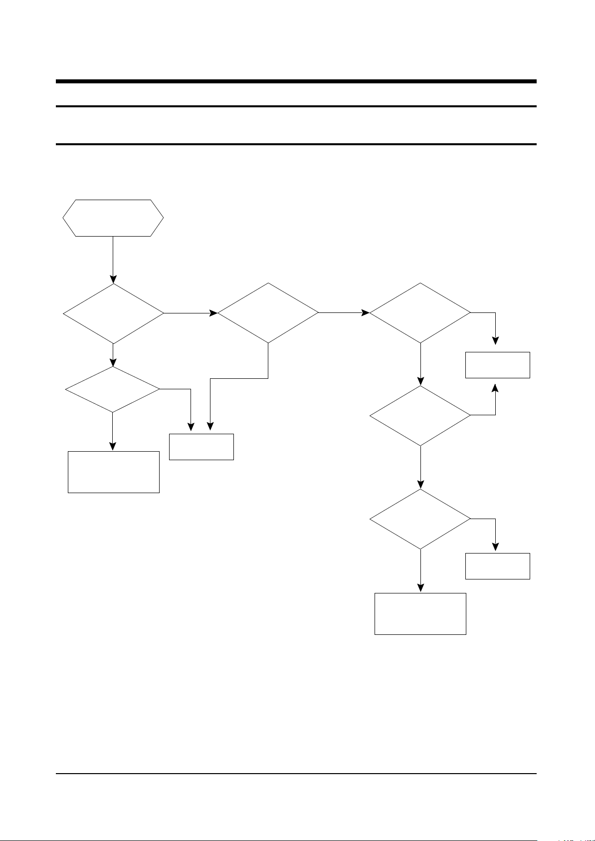
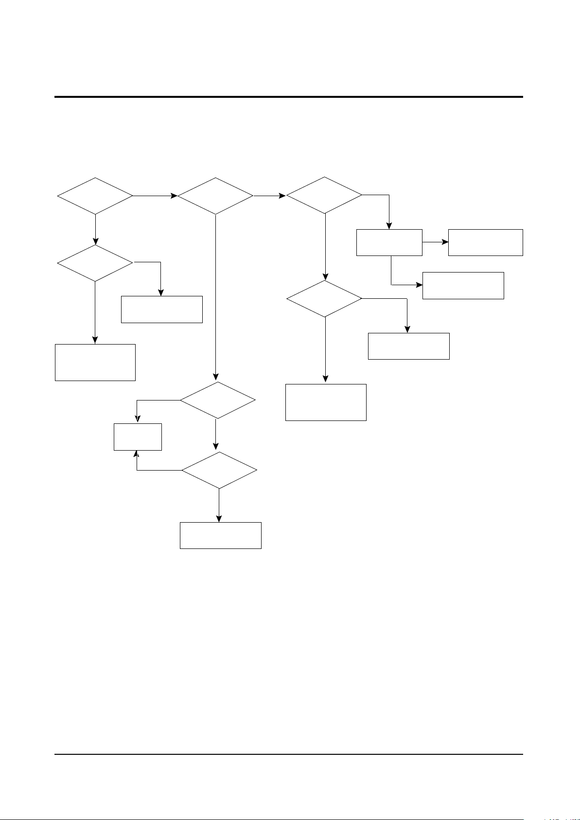
5. Troubleshooting
5-1 No Power
Counect
the Power code
Power LED
LED Off
Check the
12.5V-A Line
Abnormal
Check the
FD802S, IC801S
or AC-Fuse
Check
the
LED On
Normal
Check/Replace
IC802
Abnormal
Check the
3.3V-A,8V-A Line
of IC201S
Normal
Check the
X-tal,SDA,SCL port
of IC201S
Normal
Check the
(33)Pin (H-Drive)
of IC201S
Normal
Check the
130V- A Line
Normal
Abnormal
Replace
IC201 S
Abnormal
Abnormal
Check the
FBT,D808
Check / Replace
Q401
5-2 Samsung Electronics
5-2 No Video (Sound OK)
Troubleshooting
Check RK,GK,BK
Signal
Nornal
Check the
Voltage of heater
Nornal
Check
CRT and FBT
Abnormal
Abnormal
Check/Replace
R418,R522,R523
Abnormal
Check/Replace
IC201S
Abnormal
Check R,G,B
Signal into CRT
PCB
Abnormal
Check IC201S
Pin 51,52,53
(R.G.B)
Nornal
Check IC201S
Pin50(IK,V-GUARD)
Nornal
Check IC501
B+(180V-B)
Abnormal
Check the
resistance of R519
Nornal
Check/Replace
D407,FBT
Nornal
Check IC301
+
B Volt
-
Abnormal
Abnormal
Replace
Nornal
IC301 Check/Replace
D406,R414,D405,R413
Check/Replace
R519
Nornal
Check
CRT and FBT
 Loading...